research article biaxial solar tracking system based on...
TRANSCRIPT

Research ArticleBiaxial Solar Tracking System Based on the MPPT ApproachIntegrating ICTs for Photovoltaic Applications
Raúl Gregor,1 Yoshihiko Takase,1 Jorge Rodas,1 Leonardo Carreras,1
Derlis Gregor,2 and Andrés López1
1Department of Power and Control Systems, Faculty of Engineering, National University of Asuncion, Campus Isla Bogado,2060 Luque, Paraguay2Department of Computer Science, Faculty of Engineering, National University of Asuncion, Campus Isla Bogado,2060 Luque, Paraguay
Correspondence should be addressed to Raul Gregor; [email protected]
Received 28 November 2014; Revised 19 March 2015; Accepted 24 March 2015
Academic Editor: Francisco A. S. Neves
Copyright © 2015 Raul Gregor et al. This is an open access article distributed under the Creative Commons Attribution License,which permits unrestricted use, distribution, and reproduction in any medium, provided the original work is properly cited.
The smart grid and distributed generation based on renewable energy applications often involve the use of information andcommunication technology (ICT) coupled with advanced control and monitoring algorithms to improve the efficiency andreliability of the electrical grid and renewable generation systems. Photovoltaic (PV) systems have been recently appliedwith successin the fields of distributed generation due to their lower environmental impact where the electrical energy generation is related tothe amount of solar irradiation and thus the angle of incident ray of the sun on the surface of the modules. This paper introducesan integration of ICTs in order to achieve the maximum power point tracking (MPPT) using a biaxial solar tracking system forPV power applications. To generate the references for the digital control of azimuth and elevation angles a Global PositioningSystem (GPS) by satellites is used which enables acquiring the geographic coordinates of the sun in real-time. As a total integrationof the system a communication platform based on the 802.15.4 protocol for the wireless sensor networks (WSNs) is adopted forsupervising and monitoring the PV plant. A 2.4 kW prototype system is implemented to validate the proposed control schemeperformance.
1. Introduction
Because of the growth global electricity demand projected byInternational Energy Agency (IEA) quantified around 81%from 2011 to 2035 and the strong investment driven by anenergy policy promoted by the Kyoto Protocol which hasforced ratifying countries to reduce their emissions of green-house gases (GHG) in the recently approved second periodfrom January 2013 to December 31, 2020. This scenario hasbeen focused on the research effort in electricity generationfrom renewable energy (RE) sources. In this context, PVsystems are currently considered as one of the most usefulnatural energy sources due to their continuous cost reductionof manufacturing, fast technological progress, requiring verylittle maintenance, and being pollution-free [1, 2]. However,the power output of PV cells depends on many factors;these include the operating temperature, weather conditions,
irradiance, and angle of incidence of the solar radiation [3]. Inorder to overcome these drawbacks, maximum power shouldbe extracted from these systems using physical tracking toobtain the maximum power point tracking (MPPT). Taxon-omy of the MPPT techniques applied to PV power systemcan be found in [4]. Physical tracking involves aligningthe PV system, to be orthogonal to sun rays throughoutthe day in order to receive maximum solar radiation [5].Several methods have been implemented and evaluated tokeep the PV systems orthogonal to sun rays. An ideal solartracker must ensure that the PV cell is oriented properly,compensating for both changes in the elevation angle of thesun (throughout the day) and latitudinal offset of the sun(during seasonal changes) and changes in azimuth angle. Ithas been shown in the literature that for certain geographicalpositions up to 40% extra power per year can be producedusing a solar tracking system. These systems are usually
Hindawi Publishing CorporationInternational Journal of PhotoenergyVolume 2015, Article ID 202986, 10 pageshttp://dx.doi.org/10.1155/2015/202986

2 International Journal of Photoenergy
M M
Rotaryencoder
Rotaryencoder
Power line GNDPower line GND
elevationreference
GPS
UARTalgorithm
PWM_1
PWM_2Wireless
communication
Wirelesscommunication
Azimuth and
Azimuth
elevation referenceAzimuth and
P03/3-Modbus GPSWeather station
dsPIC33FJ128MC802 boardIndependent digital control
azimuth and elevation
QEI MCPWMencoder PWM mode
PWM
UART
USBconexion
PC monitoring
output
motorElevation
motor
5V 12V24V
Bootstrap
High/lowside driver
Vdd Vcc Vb
Vss COM
HinL inHinL in Lo
HoVs
Lo
HoVs
5V 12V24V
Bootstrap
High/lowside driver
Vdd Vcc Vb
Vss COM
HinL inHinL in Lo
HoVs
Lo
HoVs
× 2 × 2
Figure 1: Block diagram of the proposed biaxial solar tracking system based on ICTs.
classified in two categories: passive, introduced by Finsterin 1962 as a completely mechanical solution, and activethat presented a mechanism with an automatic electroniccontrol system. The above-mentioned classification of themethods can be found in [6]. Active trackers can be in turnclassified by the type of electronic control which drives themovement: in the analog type the control is generated basedon the information of a sensor that detects the position ofthe brightest point in the sky, while in the digital case, thecontrol is executed by a microprocessor which through acontrol algorithm determines the optimal position of thestructure to maximize the efficiency of the PV systems [7, 8].In both cases, the sunposition usually is detected by two light-dependent resistor (LDR) sensors that are normally locatedat both ends of the surface of the photovoltaic module. In thedigital case, the resultant signals from the sensors are fed intoan electronic control system that operates a low-speed DCmotor to rotate the PVmodules via a speed reduction system.This is a simple and inexpensive solution, but unfortunatelyit is not practical mainly in applications where weatherconditions are variable or when fast change happens in theirradiance conditions due to partial shading [9, 10]. Thispaper introduces a novel design of a biaxial solar digital track-ing system for PV power applications, using information andcommunication technologies (ICTs) to improve the efficiencyof the photovoltaic system. To generate the reference (inazimuth and elevation angle) for the digital control algorithma Global Positioning System (GPS) by satellites is used whichenables acquiring the geographic coordinates of the sunin real-time. The implementation of the control system isbased on the dsPIC33FJ128MC802 microprocessor familymanufactured by Microchip. For monitoring purposes theoverall system also provideswireless sensor networks (WSNs)based on 802.15.4 protocol, as shown in the block diagram ofFigure 1.
This paper is organized as follows. Section 2 introducesthe diode and two-diode models for a PV module and para-metric simulations for a ZDNY-100C36 series PV module.
Section 3 describes a custom-design process of the elevationand azimuthmechanism for the biaxial solar tracking system.Section 4 discusses the control strategy applied to the motorsin order to achieve the MPPT. Next, experimental results aregiven in Section 5.The conclusion is given in the last section.
2. PV Module Model Description
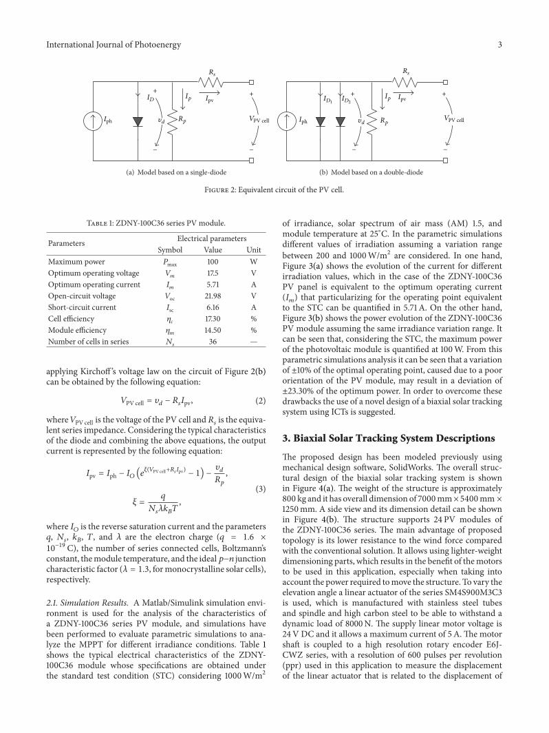
Different approaches have been implemented tomodelmath-ematically the dynamics of the PVmodules, but probably theequivalent circuit representation with single-diode and two-diode models, which are illustrated in Figure 2, represent themost widely used topologies [11–14]. The two-diode model,as shown in Figure 2(a), is characterized by its high accuracy;however, it is relatively complex and it suffers from lowcomputational speed. The second type, single-diode modelshown in Figure 2(b), is the most commonly used modelin power electronic simulation studies, because it offers areasonable tradeoffbetween simplicity and accuracy.Anotheradvantage of using the single-diode model is the possibilityto parametrize it based only on provided information bydatasheet [15]. Because of this reason, this work focuses onthe single-diode model. The simplest equivalent circuit of aPV cell is a current source in parallel with a diode as shownin Figure 2. The current source (𝐼ph) represents the currentgenerated by the PV cell due to the photons received by it,and it has invariant value under constant solar irradianceand temperature. The equations that model the PV systemperformance may be obtained from circuit representationfrom Kirchoff ’s currents law, which results in the followingequation:
𝐼ph − 𝐼𝐷
−𝜐𝑑
𝑅𝑝
− 𝐼pv = 0, (1)
where 𝐼𝐷and 𝐼pv represent the diode and cell output currents,
respectively, 𝜐𝑑is the diode voltage, and 𝑅
𝑝is the shunt
resistance in parallel with the diode. On the other hand,
International Journal of Photoenergy 3
Ip
Rs
+ +
−−
Iph
ID
Rp
Ipv
V𝜐d PV cell
(a) Model based on a single-diode
Rs
+ +
− −
Iph
Ip
Rp
Ipv
V𝜐d
ID1ID2
PV cell
(b) Model based on a double-diode
Figure 2: Equivalent circuit of the PV cell.
Table 1: ZDNY-100C36 series PV module.
Parameters Electrical parametersSymbol Value Unit
Maximum power 𝑃max 100 WOptimum operating voltage 𝑉
𝑚17.5 V
Optimum operating current 𝐼𝑚
5.71 AOpen-circuit voltage 𝑉oc 21.98 VShort-circuit current 𝐼sc 6.16 ACell efficiency 𝜂
𝑐17.30 %
Module efficiency 𝜂𝑚
14.50 %Number of cells in series 𝑁
𝑠36 —
applying Kirchoff ’s voltage law on the circuit of Figure 2(b)can be obtained by the following equation:
𝑉PV cell = 𝜐𝑑
− 𝑅𝑠𝐼pv, (2)
where 𝑉PV cell is the voltage of the PV cell and𝑅𝑠is the equiva-
lent series impedance. Considering the typical characteristicsof the diode and combining the above equations, the outputcurrent is represented by the following equation:
𝐼pv = 𝐼ph − 𝐼𝑂
(𝑒𝜉(𝑉PV cell+𝑅𝑠𝐼pv) − 1) −
𝜐𝑑
𝑅𝑝
,
𝜉 =𝑞
𝑁𝑠𝜆𝑘𝐵
𝑇,
(3)
where 𝐼𝑂is the reverse saturation current and the parameters
𝑞, 𝑁𝑠, 𝑘𝐵, 𝑇, and 𝜆 are the electron charge (𝑞 = 1.6 ×
10−19 C), the number of series connected cells, Boltzmann’s
constant, themodule temperature, and the ideal𝑝−𝑛 junctioncharacteristic factor (𝜆 = 1.3, formonocrystalline solar cells),respectively.
2.1. Simulation Results. A Matlab/Simulink simulation envi-ronment is used for the analysis of the characteristics ofa ZDNY-100C36 series PV module, and simulations havebeen performed to evaluate parametric simulations to ana-lyze the MPPT for different irradiance conditions. Table 1shows the typical electrical characteristics of the ZDNY-100C36 module whose specifications are obtained underthe standard test condition (STC) considering 1000W/m2
of irradiance, solar spectrum of air mass (AM) 1.5, andmodule temperature at 25∘C. In the parametric simulationsdifferent values of irradiation assuming a variation rangebetween 200 and 1000W/m2 are considered. In one hand,Figure 3(a) shows the evolution of the current for differentirradiation values, which in the case of the ZDNY-100C36PV panel is equivalent to the optimum operating current(𝐼𝑚) that particularizing for the operating point equivalent
to the STC can be quantified in 5.71 A. On the other hand,Figure 3(b) shows the power evolution of the ZDNY-100C36PV module assuming the same irradiance variation range. Itcan be seen that, considering the STC, the maximum powerof the photovoltaic module is quantified at 100W. From thisparametric simulations analysis it can be seen that a variationof ±10% of the optimal operating point, caused due to a poororientation of the PV module, may result in a deviation of±23.30% of the optimum power. In order to overcome thesedrawbacks the use of a novel design of a biaxial solar trackingsystem using ICTs is suggested.
3. Biaxial Solar Tracking System Descriptions
The proposed design has been modeled previously usingmechanical design software, SolidWorks. The overall struc-tural design of the biaxial solar tracking system is shownin Figure 4(a). The weight of the structure is approximately800 kg and it has overall dimension of 7000mm× 5400mm ×
1250mm. A side view and its dimension detail can be shownin Figure 4(b). The structure supports 24 PV modules ofthe ZDNY-100C36 series. The main advantage of proposedtopology is its lower resistance to the wind force comparedwith the conventional solution. It allows using lighter-weightdimensioning parts, which results in the benefit of themotorsto be used in this application, especially when taking intoaccount the power required tomove the structure. To vary theelevation angle a linear actuator of the series SM4S900M3C3is used, which is manufactured with stainless steel tubesand spindle and high carbon steel to be able to withstand adynamic load of 8000N. The supply linear motor voltage is24V DC and it allows a maximum current of 5A.The motorshaft is coupled to a high resolution rotary encoder E6J-CWZ series, with a resolution of 600 pulses per revolution(ppr) used in this application to measure the displacementof the linear actuator that is related to the displacement of

4 International Journal of Photoenergy
6
4
2
0
Curr
ent (
A)
1000800
600400
200Irradiance (W/m 2)
0 5 10 15 20 25
6
5
4
3
2
1
Voltage (V)
(a) Current versus voltage curves for different irradiation values
1000800
600400
200Irradiance (W/m 2)
0 5 10 15 20 25
Voltage (V)
100
50
0
Pow
er (W
)
80
60
40
20
0
(b) Power versus voltage curves for different irradiation values
Figure 3: Parametric simulations of the ZDNY-100C36 series PV module.
x
y
z
(a) Global design of the structure
85
𝜙15.875
80
A
A
810
0
60∘
5384
5384
1507.300
6900
E
E
1250
1000
D
D
100
750
𝜙15.875
(b) Side view, dimensions, and details
Figure 4: Mechanical design based on the SolidWorks computational tool.
the structure in elevation angle. Then, to change the azimuthangle a 12V DC motor is used and it coupled to a speedreduction system with a reduction ratio of 1 : 70000. Themotor shaft is coupled to a high resolution incrementalencoder (E6B2-CWZ6C series with a resolution of 400 ppr)to measure the position of the structure in azimuthal axis.In both cases, the position of the structure is determined inreal-time and it is transmitted wirelessly using the 802.15.4protocol to the main computer that is used for controllingand monitoring the PV plant. The reference for the controlsystem (in azimuth and elevation angle) is provided by theP03/3-Modbus GPS weather station by using a proprietaryalgorithm. This device measures temperature, wind speed,and brightness (eastern, southern, and western sunlight).Moreover, it recognizes precipitation and it receives theUniversal Time Coordinated (UTC) signals as well as the sitecoordinates via an integrated GPS receiver. The direction ofthe sun (azimuth) as well as its height (elevation) is calculatedwith the above details and then it is transmitted to the maincomputer wirelessly by a pair of series 2 XBee. Moreover,the references input to the control algorithm (azimuth andelevation angle) are transmitted using a pair of series 1 XBee
Pro.The initial and final positions of the biaxial solar trackingsystem are electronically detected by limit switches sensors. Adetailed block diagram of the proposed biaxial solar trackingapplied to the photovoltaic system is provided in Figure 1.
3.1. Elevation Mechanism. The different components used inthe implementation of the biaxial solar tracking system forPV applications have been manufactured by using materialsthat comply with international standards of wind loadsaccording to ISO 4354 specification. The overall system hasbeen assembled according to the proposed design shown inFigure 4. On the other hand, Figure 5(a) showed the designof the elevation motionmechanism where the linear actuatorcoupled to an arm used to articulate the movement can beseen. Moreover, Figure 5(b) shows a picture of the elevationmechanism implemented.
3.1.1. Linear Motor Model. Assuming the generic transferfunction (TF) of the DC motor as the relationship betweenthemechanical speed (𝜔)measured in revolutions perminute(rpm) and the voltage applied to the motor (𝑉
𝑠𝑒) and con-
sidering the electrical and mechanical parameters, the motor

International Journal of Photoenergy 5
(a) Elevation mechanism design with SolidWorks computa-tional tool
(b) Elevation mechanism implemented to articulate the move-ment
Figure 5: Mechanism of elevation motion and linear actuator.
model can be approximated by a second-order equation asfollows:
𝜔 (𝑠)
𝑉𝑠𝑒 (𝑠)
=𝐾𝐸𝑒
𝐿𝑎𝑒
𝐽𝑀𝑒
𝑠2+(𝑅𝑎𝑒
𝐽𝑀𝑒
+ 𝐷𝑀𝑒
𝐿𝑎𝑒
) 𝑠+(𝐾2
𝐸𝑒+ 𝑅𝑎𝑒
𝐷𝑀𝑒
),
(4)
where 𝑅𝑎𝑒, 𝐿𝑎𝑒, 𝐾𝐸𝑒, 𝐽𝑀𝑒
, and 𝐷𝑀𝑒
are the armature electricresistance and the inductance, the back electromagneticforce constant, the moment of inertia, and the viscousfriction coefficient, respectively. Table 2 shows the values ofthe parameters measured experimentally for the particularcase of the linear actuator SM4S900M3C3. Considering asampling frequency of 1.5Hz and assuming that the TF ispreceded by a zero-order hold (ZOH), the TF in discrete timecan be written using the state-space representation approachas follows:
x𝑒(𝑘+1|𝑘)
= A𝑒x𝑒(𝑘|𝑘)
+ B𝑒u𝑒(𝑘|𝑘)
,
y𝑒(𝑘|𝑘)
= C𝑒x𝑒(𝑘|𝑘)
,
(5)
where u𝑒is the input voltage, x
𝑒= [V
𝑠𝑒, 𝜔]𝑇 is the state
vector, and A𝑒and B
𝑒are matrices that define the dynamics
of the linear motor that for this set of state variables using thecanonical form of control representation are defined as
A𝑒
= [
1.952314938166575 −0.952378714704760
1 0] ,
B𝑒
= [1 0]𝑇
,
C𝑒
= [0.009456745359447 0.009304185583616] .
(6)
Figure 6 shows the experimental validation of the math-ematical model implemented using the Matlab/Simulinkcomputational tool for 7 operation points in open loop. Itcan be seen in the figure that the step response obtainedby simulations converges to the experimental values whendifferent voltage excitation levels (from 12 to 24 volts, in stepof 2V) are applied to the motor.
Table 2: Linear motor SM4S900M3C3 series parameters.
Parameters Electrical and mechanical parametersSymbol Value Unit
Armature electric resistance 𝑅𝑎𝑒
1.425 Ω
Armature electric inductance 𝐿𝑎𝑒
0.0015 HBack EMF constant 𝐾
𝐸𝑒0.031 V⋅s/rad
Torque constant 𝐾𝑇𝑒
0.031 V⋅s/radCurrent source 𝑖
𝐹𝑒0.27 A
Moment of inertia 𝐽𝑀𝑒
27 × 10−6 kg⋅m2
Viscous coefficient 𝐷𝑀𝑒
3.18 × 10⁻⁶ Nm⋅s/rad
3.2. Azimuth Mechanism. Azimuth mechanism is based ona speed reduction system coupled to a DC motor, as shownin Figure 7(a). In order to reduce the speed of azimuth, themechanism uses a combined system of two levels crown-pinion using a chain drive coupled turn to the worm gearreducer box. The structure rotates in azimuthal directionusing a ball bearing steel system to reduce the friction effects.This procedure allows the use of low power DC motors tomove the PV system. The azimuth mechanism implementedis shown in Figure 7(b). The structure was manufacturedfrom pieces formed by steel tubes and profiles using arcwelding. The unions of the removable parts were performedusing stainless steel screws. Each of the brackets, having8 PV modules of 100W nominal power, has been arrangedas shown in the photograph in Figure 1. The overall systemdesigned provides a maximum power of 2.4 kW.
3.2.1. Azimuthal Motor Model. In the same way as forthe previous case electrical and mechanical parameters ofazimuth motor have been measured experimentally in orderto represent the mathematical model in the state-space.Table 3 shows the values of the parameters measured. Indiscrete time the mathematical model of the azimuth motorcan be written as follows:
x𝑎(𝑘+1|𝑘)
= A𝑎x𝑎(𝑘|𝑘)
+ B𝑎u𝑎(𝑘|𝑘)
,
y𝑎(𝑘|𝑘)
= C𝑎x𝑎(𝑘|𝑘)
,(7)

6 International Journal of Photoenergy
Vs = 12V Vs = 14VVs = 16V Vs = 18VVs = 20V Vs = 22VVs = 24V
0 20 40 60 80 100
Time (ms)
0
3000
4000
1000
2000
5000
6000
7000
8000
Spee
d (r
pm)
(a) Results obtained by simulations
0
3000
4000
1000
2000
5000
6000
7000
8000
0 20 40 60 80 100
Time (ms)
Spee
d (r
pm)
Vs = 12V Vs = 14VVs = 16V Vs = 18VVs = 20V Vs = 22VVs = 24V
(b) Results obtained experimentally
Figure 6: Step response of the linear motor speed.
(a) Azimuth mechanism design with SolidWorks computa-tional tool
(b) Azimuth mechanism implemented to articulate the movement
Figure 7: Mechanism of azimuth motion and speed reduction system.
Table 3: Azimuth motor parameters.
Parameters Electrical and mechanical parametersSymbol Value Unit
Armature electric resistance 𝑅𝑎𝑎
1.6 Ω
Armature electric inductance 𝐿𝑎𝑎
0.002 HBack EMF constant 𝐾
𝐸𝑎0.0245 V⋅s/rad
Torque constant 𝐾𝑇𝑎
0.0245 V⋅s/radCurrent source 𝑖
𝐹𝑎0.754 A
Moment of inertia 𝐽𝑀𝑎
16 × 10−6 kg⋅m2
Viscous coefficient 𝐷𝑀𝑎
16 × 10−6 Nm⋅s/rad
where u𝑎is the input voltage, x
𝑎= [V
𝑠𝑎, 𝜔𝑎]𝑇 is the state
vector, and A𝑎and B
𝑎are matrices that define the dynamics
of the azimuthalmotor that for this set of state variables usingare defined as
A𝑎
= [
1.959704907964181 −0.959755299777461
1 0] ,
B𝑎
= [1 0]𝑇
,
C𝑎
= 1 × 10⁻⁴
[0.758665307052543 0.748348332271132] .
(8)
Figure 8 shows the experimental validation of the math-ematical model implemented using the Matlab/Simulinkcomputational tool for 4 operation points in open loop. Itcan be seen in the figure that the step response obtained bysimulations converges to the experimental values when it isapplied to the motor different voltage excitation levels, from8 to 14 volts in step of 2V, respectively.

International Journal of Photoenergy 7
0 30 60 90 120 150 180 210 240
50
45
40
35
30
25
20
15
10
5
0
Spee
d (r
pm)
Time (ms)V = 8V V = 10VV = 12V V = 14V
(a) Results obtained by simulations
50
45
40
35
30
25
20
15
10
5
0
Spee
d (r
pm)
0 30 60 90 120 150 180 210 240
Time (ms)V = 8V V = 10VV = 12V V = 14V
(b) Results obtained experimentally
Figure 8: Step response of the azimuth motor speed.
SV
PV(t)
+ +
− −
−
P
D
Ie(t)KP
MV(t) 𝜃𝜔 1
s
x(k+1|k) = Ax(k|k) + Bu(k|k)y(k|k) = Cx(k|k)
Advanced PID
TD · s
1
TI · s
Figure 9: Advanced-PID position controller.
4. Control Strategy
In order to control the position of the structure, an advanced-proportional integral derivative (Advanced-PID) controlalgorithm has been implemented. The main advantage ofthe Advanced-PID control approach is its low computationalburden to carry out the control. The performance of theAdvanced-PID can be also modified by varying the threecontrol variables. In the proposed scheme the Advanced-PIDcontroller computes an error value as the difference betweena measured variable (the structure position obtained by theencoder sensors) and a desired setpoint (the sun positionobtained from theGPS by theweather station).The controllerattempts to minimize the error by adjusting the processcontrol inputs using the scheme shown in the block diagramof Figure 9.
The discrete implementation can be obtained from theblock diagram using approximations for first order to deriva-tives by backward finite differences [16].Thus the integral andderivative terms can be discretized with a sampling time Δ𝑡;as a result the control equations can be written as follows:
Δ𝑀𝑉𝑘
= 𝐾𝑃
((𝑒𝑘
− 𝑒𝑘−1
) +Δ𝑡
𝑇𝐼
𝑒𝑘
+𝑇𝐷
Δ𝑡(𝑒𝑘
− 2𝑒𝑘−1
+ 𝑒𝑘−2
)) ,
(9)
𝑀𝑉𝑘
= 𝑀𝑉𝑘−1
+ Δ𝑀𝑉𝑘, (10)
where 𝐾𝑃, 𝑇𝐼, 𝑇𝐷, and 𝑒
𝑘represent the proportional gain,
integral and derivative time, and the error, respectively. Inorder to minimize the effects of the noise on the proposedcontrol strategy, the term (𝑒
𝑘− 𝑒𝑘−1
) in (9) is replaced by(PV𝑘−1
−PV𝑘). Algorithm 1 shows the pseudocodeAdvanced-
PID control algorithm, where the control effort is applied tothe azimuth and elevationmechanisms at each sampling timein terms of duty cycle.
An interval control mode for small displacements hasbeen applied to the simultaneous (elevation and azimuth)motors in order to evaluate the efficiency of the Advanced-PID control algorithm. The result of the interval control isshown in Figure 10. Advanced-PID position control was per-formed under a PWM frequency of 19.5 kHz and the values ofproportional gain and integral and derivative time (𝐾
𝑃= 20,
𝑇𝐼
= 0.6, and 𝑇𝐷
= 0.3) have been calculated initially usingthe Ziegler-Nichols method and have been subsequentlyadjusted by heuristic rules to obtain an acceptable dynamicresponse. Figure 10(a) shows the multistep response of thelinear motor for small displacements. This figure shows thatthe proposed Advanced-PID position control implementedhas a good dynamic response considering parameters in thetime-domain tests as rise time (around 3 s), settling time(around 5 s), and overshoot and steady-state error (near zero).

8 International Journal of Photoenergy
Input: 𝑆𝑉𝑘
:= 𝑅𝑒𝑎𝑑𝐺𝑃𝑆(); //Set position references form the GPS
𝑀𝑉𝑘−1
:= 0, 𝑃𝑉𝑘−2
:= 0, 𝑃𝑉𝑘−1
:= 0; //Set initial values
while 𝑡 = Δ𝑡 do𝑃𝑉𝑘
:= 𝑅𝑒𝑎𝑑𝐸𝑛𝑐𝑜𝑑𝑒𝑟(); //Read encoder values
𝑒𝑘
:= 𝑆𝑉𝑘
− 𝑃𝑉𝑘; //The position error is calculated
𝐷𝑘
:= −𝐾𝑃
⋅ (𝑇𝐷
/Δ𝑡) ⋅ (𝑃𝑉𝑘
− 2 ⋅ 𝑃𝑉𝑘−1
+ 𝑃𝑉𝑘−2
); //The derivative term is calculated
Δ𝑀𝑉𝑘
:= −𝐾𝑃
⋅ (𝑃𝑉𝑘
− 𝑃𝑉𝑘−1
) + 𝐾𝑃
⋅ (Δ𝑡/𝑇𝐼) ⋅ 𝑒𝑘
+ 𝐷𝑘; //Total control term is calculated
𝑀𝑉𝑘
:= 𝑀𝑉𝑘−1
+ Δ𝑀𝑉𝑘;
𝑀𝑉𝑘−1
:= 𝑀𝑉𝑘, 𝑃𝑉𝑘−2
:= 𝑃𝑉𝑘−1
, 𝑃𝑉𝑘−1
:= 𝑃𝑉𝑘, 𝑡 := 0; //Variables are stored
𝐴𝑝𝑝𝑙𝑖𝑒𝑑𝑃𝑊𝑀(𝑀𝑉); //Control effort is applied
end
Algorithm 1: Advanced-PID position controller.
0 10 20 30 40 50
Time (s)
7
6
5
4
3
2
1
0
Line
ar m
otor
pos
ition
(mm
)
Experimental resultsSet variable
(a) Linear motor response for𝐾𝑃 = 20, 𝑇𝐼 = 0.6, and 𝑇𝐷 = 0.3
0 10 20 30 40 50
Time (s)
300
250
200
150
100
50
0
−50
Mot
or p
ositi
on (d
eg)
Experimental resultsSet variable
(b) Azimuthal motor response for𝐾𝑃 = 20, 𝑇𝐼 = 0.6, and 𝑇𝐷 = 0.3
Figure 10: Position step response of the linear and azimuth motors for small displacements.
Moreover, Figure 10(b) shows the multistep angle responseof the azimuth motor, where it can be seen that the dynamicresponse converges to the reference values with steady-stateerror (near zero).
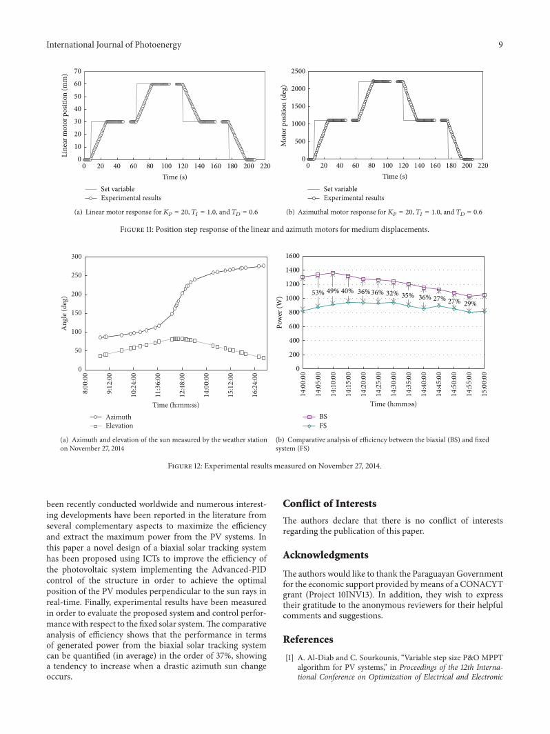
Figure 11 shows the experimental results for mediumdisplacements and for different values of proportional gainand integral and derivative time (𝐾
𝑃= 20, 𝑇
𝐼= 1.0, and𝑇
𝐷=
0.6). As can be seen in Figure 11(a) (for the case of the linealmotor) and Figure 11(b) (for the case of the azimuth motor)the multistep response converges to the reference values withsteady-state error (near zero), even if it is consideredmediumdisplacements.
5. Experimental Results
Theproposed control strategywas tested in the 2.4 kWbiaxialtracking system, taking a variable elevation and azimuth sun’sangle as the reference, provided by the P03/3-Modbus GPSweather station as shown in Figure 12(a). The linear andazimuth motors were fed through an H-Bridge driver usedto generate two independent 19.5 kHz PWM signals basedon the locked antiphase (LA) technique. The Advanced-PIDposition control was performed under a sampling frequencyof 1.5Hz using the following values of gains for the PIDalgorithm: 𝐾
𝑃= 20, 𝑇
𝐼= 0.6, and 𝑇
𝐷= 0.3, which
have been tuned by heuristic rules to obtain an acceptabledynamic response. Figure 12(b) shows a comparative analysisof the efficiency between the proposed biaxial tracking systemtaking as reference the fixed system, under the same electricalconnection scheme and load conditions. The total powergenerated was quantified in 5-minute intervals under no-ideal weather conditions (slightly cloudy) for both topologies(biaxial and fixed system). The fixed system was positionedwith an elevation angle of 25.2972 degrees (which is the sameas the site’s latitude where the biaxial solar tracking systemwas implemented) and the azimuth was zero degrees to get itoriented in north-south direction. As shown in Figure 12(b),the biaxial solar tracking system yielded higher power andlower degradation of the power than the fixed system within1 h of testing.The results show that the proposed biaxial solartracking system introduces an average improvement of 37%compared with the results obtained from a fixed solar system.
6. Conclusion
The field of renewable energies has experienced a substantialgrowth in the last decades in which the photovoltaic appli-cation has been one of the most active research areas due tothe costs reduction and increment of efficiency. Research has
International Journal of Photoenergy 9
Experimental resultsSet variable
0 20 40 60 80 100 120 140 160 180 200 220
Time (s)
70
60
50
40
30
20
10
0
Line
ar m
otor
pos
ition
(mm
)
(a) Linear motor response for𝐾𝑃 = 20, 𝑇𝐼 = 1.0, and 𝑇𝐷 = 0.6
0 20 40 60 80 100 120 140 160 180 200 220
Time (s)
2500
2000
1500
1000
500
0
Mot
or p
ositi
on (d
eg)
Experimental resultsSet variable
(b) Azimuthal motor response for𝐾𝑃 = 20, 𝑇𝐼 = 1.0, and 𝑇𝐷 = 0.6
Figure 11: Position step response of the linear and azimuth motors for medium displacements.
8:00
:00
9:12
:00
10:2
4:00
11:3
6:00
12:4
8:00
14:0
0:00
15:1
2:00
16:2
4:00
300
250
200
150
100
50
0
Ang
le (d
eg)
AzimuthElevation
Time (h:mm:ss)
(a) Azimuth and elevation of the sun measured by the weather stationon November 27, 2014
1600
1400
1200
1000
800
600
400
200
0
53% 40%49% 36%36% 32% 35% 36% 27% 27% 29%
Pow
er (W
)
Time (h:mm:ss)
BSFS
14:00
:00
14:05
:00
14:10
:00
14:15
:00
14:20
:00
14:25
:00
14:30
:00
14:35
:00
14:40
:00
14:45
:00
14:50
:00
14:55
:00
15:00
:00
(b) Comparative analysis of efficiency between the biaxial (BS) and fixedsystem (FS)
Figure 12: Experimental results measured on November 27, 2014.
been recently conducted worldwide and numerous interest-ing developments have been reported in the literature fromseveral complementary aspects to maximize the efficiencyand extract the maximum power from the PV systems. Inthis paper a novel design of a biaxial solar tracking systemhas been proposed using ICTs to improve the efficiency ofthe photovoltaic system implementing the Advanced-PIDcontrol of the structure in order to achieve the optimalposition of the PV modules perpendicular to the sun rays inreal-time. Finally, experimental results have been measuredin order to evaluate the proposed system and control perfor-mancewith respect to the fixed solar system.The comparativeanalysis of efficiency shows that the performance in termsof generated power from the biaxial solar tracking systemcan be quantified (in average) in the order of 37%, showinga tendency to increase when a drastic azimuth sun changeoccurs.
Conflict of Interests
The authors declare that there is no conflict of interestsregarding the publication of this paper.
Acknowledgments
The authors would like to thank the Paraguayan Governmentfor the economic support provided bymeans of a CONACYTgrant (Project 10INV13). In addition, they wish to expresstheir gratitude to the anonymous reviewers for their helpfulcomments and suggestions.
References
[1] A. Al-Diab and C. Sourkounis, “Variable step size P&O MPPTalgorithm for PV systems,” in Proceedings of the 12th Interna-tional Conference on Optimization of Electrical and Electronic

10 International Journal of Photoenergy
Equipment (OPTIM ’10), pp. 1097–1102, IEEE, Bras,ov, Romania,May 2010.
[2] R. S. Munoz-Aguilar, P. Rodriguez, G. Vazquez, I. Candela,and E. Aldabas, “Efficiency analysis of DCM-232 three-phasePV topology,” in Proceedings of the 38th Annual Conference onIEEE Industrial Electronics Society (IECON ’12), pp. 5714–5719,Montreal, Canada, October 2012.
[3] J. Shi,W.-J. Lee, Y. Liu, Y. Yang, and P.Wang, “Forecasting poweroutput of photovoltaic systems based on weather classificationand support vector machines,” IEEE Transactions on IndustryApplications, vol. 48, no. 3, pp. 1064–1069, 2012.
[4] B. Subudhi and R. Pradhan, “A comparative study onmaximumpower point tracking techniques for photovoltaic power sys-tems,” IEEE Transactions on Sustainable Energy, vol. 4, no. 1, pp.89–98, 2013.
[5] A. Al Nabulsi and R. Dhaouadi, “Efficiency optimization of adsp-based standalone PV system using fuzzy logic and dual-MPPT control,” IEEE Transactions on Industrial Informatics,vol. 8, no. 3, pp. 573–584, 2012.
[6] H. Mousazadeh, A. Keyhani, A. Javadi, H. Mobli, K. Abrinia,and A. Sharifi, “A review of principle and sun-trackingmethodsfor maximizing solar systems output,” Renewable and Sustain-able Energy Reviews, vol. 13, no. 8, pp. 1800–1818, 2009.
[7] M. J. Clifford and D. Eastwood, “Design of a novel passive solartracker,” Solar Energy, vol. 77, no. 3, pp. 269–280, 2004.
[8] F. R. Rubio, M. G. Ortega, F. Gordillo, and M. Lopez-Martinez,“Application of new control strategy for sun tracking,” EnergyConversion andManagement, vol. 48, no. 7, pp. 2174–2218, 2007.
[9] C. S. Chin, A. Babu, and W. McBride, “Design, modeling andtesting of a standalone single axis active solar tracker usingMATLAB/Simulink,” Renewable Energy, vol. 36, no. 11, pp.3075–3090, 2011.
[10] F. Scarpetta, M. Liserre, and R. A. Mastromauro, “Adaptive dis-tributedMPPT algorithm for photovoltaic systems,” in Proceed-ings of the 38thAnnual Conference on IEEE Industrial ElectronicsSociety (IECON ’12), pp. 5708–5713, Montreal, Canada, October2012.
[11] K. Ding, X. Bian, H. Liu, and T. Peng, “A MATLAB-simulink-based PV module model and its application under conditionsof nonuniform irradiance,” IEEE Transactions on Energy Con-version, vol. 27, no. 4, pp. 864–872, 2012.
[12] W. Xiao, F. F. Edwin, G. Spagnuolo, and J. Jatskevich, “Efficientapproaches for modeling and simulating photovoltaic powersystems,” IEEE Journal of Photovoltaics, vol. 3, no. 1, pp. 500–508, 2013.
[13] L. V. Hartmann, M. A. Vitorino, M. B. Rossite, and A. M.N. Lima, “Combining model-based and heuristic techniquesfor fast tracking the maximum-power point of photovoltaicsystems,” IEEE Transactions on Power Electronics, vol. 28, no. 6,pp. 2875–2885, 2013.
[14] D. Giaffreda, P. Magnone, M. Meneghini et al., “Local shuntingin multicrystalline silicon solar cells: distributed electricalsimulations and experiments,” IEEE Journal of Photovoltaics,vol. 4, no. 1, pp. 40–47, 2014.
[15] Y. A. Mahmoud, W. Xiao, and H. H. Zeineldin, “A parame-terization approach for enhancing PV model accuracy,” IEEETransactions on Industrial Electronics, vol. 60, no. 12, pp. 5708–5716, 2013.
[16] G. Franklin, J. D. Powell, and M. L. Workman, “Review ofcontinuous control,” in Digital Control of Dynamic Systems, pp.23–24, Addison-Wesley, Menlo Park, Calif, USA, 3rd edition,1998.

Submit your manuscripts athttp://www.hindawi.com
Hindawi Publishing Corporationhttp://www.hindawi.com Volume 2014
Inorganic ChemistryInternational Journal of
Hindawi Publishing Corporation http://www.hindawi.com Volume 2014
International Journal ofPhotoenergy
Hindawi Publishing Corporationhttp://www.hindawi.com Volume 2014
Carbohydrate Chemistry
International Journal of
Hindawi Publishing Corporationhttp://www.hindawi.com Volume 2014
Journal of
Chemistry
Hindawi Publishing Corporationhttp://www.hindawi.com Volume 2014
Advances in
Physical Chemistry
Hindawi Publishing Corporationhttp://www.hindawi.com
Analytical Methods in Chemistry
Journal of
Volume 2014
Bioinorganic Chemistry and ApplicationsHindawi Publishing Corporationhttp://www.hindawi.com Volume 2014
SpectroscopyInternational Journal of
Hindawi Publishing Corporationhttp://www.hindawi.com Volume 2014
The Scientific World JournalHindawi Publishing Corporation http://www.hindawi.com Volume 2014
Medicinal ChemistryInternational Journal of
Hindawi Publishing Corporationhttp://www.hindawi.com Volume 2014
Chromatography Research International
Hindawi Publishing Corporationhttp://www.hindawi.com Volume 2014
Applied ChemistryJournal of
Hindawi Publishing Corporationhttp://www.hindawi.com Volume 2014
Hindawi Publishing Corporationhttp://www.hindawi.com Volume 2014
Theoretical ChemistryJournal of
Hindawi Publishing Corporationhttp://www.hindawi.com Volume 2014
Journal of
Spectroscopy
Analytical ChemistryInternational Journal of
Hindawi Publishing Corporationhttp://www.hindawi.com Volume 2014
Journal of
Hindawi Publishing Corporationhttp://www.hindawi.com Volume 2014
Quantum Chemistry
Hindawi Publishing Corporationhttp://www.hindawi.com Volume 2014
Organic Chemistry International
ElectrochemistryInternational Journal of
Hindawi Publishing Corporation http://www.hindawi.com Volume 2014
Hindawi Publishing Corporationhttp://www.hindawi.com Volume 2014
CatalystsJournal of