research article crowd motion editing based on mesh
TRANSCRIPT
Research ArticleCrowd Motion Editing Based on Mesh Deformation
Yong Zhang , Xinyu Zhang, Tao Zhang, and Baocai Yin
Beijing Key Laboratory of Multimedia and Intelligent Software Technology, Faculty of Information Technology, Beijing Universityof Technology, Beijing 100124, China
Correspondence should be addressed to Yong Zhang; [email protected]
Received 17 January 2020; Accepted 16 November 2020; Published 8 December 2020
Academic Editor: Floriano De Rango
Copyright © 2020 Yong Zhang et al. This is an open access article distributed under the Creative Commons Attribution License,which permits unrestricted use, distribution, and reproduction in any medium, provided the original work is properly cited.
Computer simulation is a significant technology on making great scenes of crowd in the film industry. However, current animationmaking process of crowdmotion requires large manual operations which are time-consuming and inconvenient. To solve the aboveproblem, this paper presents an editing method on the basis of mesh deformation that can rapidly and intuitively edit crowdmovement trajectories from the perspective of time and space. The method is applied to directly generate and adjust the crowdmovement as well as avoid the crash between crowd and obstacles. As for collisions within the crowd that come along with pathmodification problem, a time-based solution is put forward to avoid this situation by retaining relative positions of individuals.Moreover, an experiment based on a real venue was performed and the result indicates that the proposed method can not onlysimplify the editing operations but also improve the efficiency of crowd motion editing.
1. Introduction
Computer simulation of crowd movement refers to settingup simulation models depending on crowd motion featuresin the reality, which means imitating the movement processof a bunch of people in the virtual environment. This tech-nique is so useful that has been widely applied in the fieldof architecture, transportation safety, computer games, ani-mation, and so on. In terms of film and television production,it can save time and massive money in making collectivescenes that involved a large group of people, for instance,the battle scenes. Under the circumstance, it is meaningfulto develop the production method of crowd animation,which would improve the productivity and make promotionto the animation industry.
Up to now, the making process of crowd animation relieson quantity of manual operations and it is difficult to editevery individual manually in large-scale crowd motion, espe-cially when one’s appearance time needs to be precise or thespeed of a certain group of people has to change over time. Inaddition, the influence on crowd formation and speedbrought by editing is hard to eliminate. When adjusting thepace or routes of a small part of people in the group, thespeed of the whole crowd often changes in a mutation which
looks strange for walking people. Besides, collision matters arelikely to occur after editing crowd motion and improper solu-tions may cause extensive crash among virtual characters.According to previous studies, crowd behavior simulationunder different circumstances has been widely researched,such as simulating the crowd rushing to exits in a closed room[1] and establishing an interactive simulation model to imitatehuman-like behaviors among people as well as their influenceto the environment [2]. Furthermore, many researchers paidattention to the calculation efficiency and large-scale crowdvisualization. Wong et al. improved a model by combiningclustering and spring force to govern individual movementin the virtual environment [3]. With the broad application ofneural network, motion rules can be learned from real dataso that human walking can be simulated in higher speed [4].In terms of crowd formation, Hughes [5] considered crowdas flow continuum and continuum models have been set upto capture key features of pedestrian flows [6]. Nevertheless,the editing of crowd animation during the simulation processhas been rarely studied. Therefore, this paper is aimed at pro-posing a method to effectively edit the crowd motion.
Inspired by the cage-based editing method by Kwon et al.[7], we adopt concave hull to encircle the crowd and adjust itsmotion as a whole, which was able to intuitively edit the
HindawiInternational Journal of Digital Multimedia BroadcastingVolume 2020, Article ID 3634054, 13 pageshttps://doi.org/10.1155/2020/3634054
crowd by dragging characters. Moreover, triangular mesh isused to establish topological relation among characters inthe virtual population in order to maintain their relativepositions. The modification process relies on the mesh defor-mation technique proposed by Liu et al. [8]. In addition,according to the editorial way mentioned by Kim et al. [9],this paper divide crowd movement into a spatial part andtemporal part to adjust crowd formation and solve collisionproblems.
There are three main contributions of this research:
(i) The proposed method can effectively edit the crowdmotion both collectively and individually
(ii) The method is able to retain the formation of thecrowd and the relative positions between characters.Moreover, the collision problems between character-s/obstacles are handled
(iii) The method is suitable for simulating activities thatneeded fixed relationships among participants, suchas the march-in ceremony and military review
2. Related Work
Crowd simulation technology mainly includes modeling andsimulation of virtual people’s behaviors, group animation,and visualization of virtual crowd. Many researchers haveexplored the manners of virtual people. The seminal contri-bution to the simulation of crowd’s behaviors should be thework of Reynolds [10] in 1987. They thought flock behaviorswere the dense interactions of the relatively simple mannersof the individuals. In addition, a distributed model was setup to generate the simple individual behaviors and complexflock behaviors evolved from individual behaviors. Reeves[11] proposed a particle system which is a collection of min-ute particles, modeling irregular fuzzy object. Musse andThalmann [12] presented a Vi-Crowd model, including ahierarchy of crowds, groups, and individuals. Each level ofautonomy had its own behavioral rule, and the complexcrowd behaviors were simulated by synthetic effects amongall hierarchies, which took sociological aspects into consider-ation. On the basis of the above model, psychological effectswere considered for crowd movement by Pelechano et al.[13]. Moreover, Chenney [14] described a method for repre-senting and designing speed fields by using flow tiles, whichrealized the minimum impact from the mixture of socialand psychological influences.
In the field of group animation, which is a branch ofcrowd simulation, Ji et al. [15] carried out researches on thealgorithm of group movement simulation and proposed amethod for group calisthenics based on group events. Taka-hashi et al. [16] presented a spectral-based approach to con-trol the temporal and spatial distribution of individuals bymapping the group formation into the rotation interpolationof Laplace matrix eigenbases. Kovar et al. [17] suggested anovel method based on motion graph which was automati-cally constructed, and walks can be built on the graph to gen-erate motion. Interactive manipulation of multicharacteranimation was initially proposed by Kwon et al. [18]. They
used a graph structure to model the spatiotemporal groupbehaviors of the crowd and employed a mesh-editing algo-rithm to manipulate the animation interactively. Ulicnyet al. [19] put forward the concept of crowdbrush that userscould brush in three-dimensional scenes with a brush meta-phor, and then the system would generate a crowd in thebrushed place. Furthermore, different brush colors form dis-tinct crowd behaviors. Allain et al. [20] applied constraints tocontrol the crowd. Different from other methods, theydivided the constraints into macroconstraints and microcon-straints. Macroconstraints were used to constrain the macro-scopic characteristics of the crowd, for example, the speedfield; microconstraints were used to constrain the crowdspeed, location, and so on.
3. Crowd Motion Editing Based onMesh Deformation
Crowd scenes are commonly used in animation, but groupmotion is complicated and difficult to modify. For specificscenes that required large crowd, such us parade and masschoreography, if we could edit people’s movement in astraightforward way, what you see is what you get, it wouldbe a useful method to simulate crowd animation. Therefore,this paper proposed a method that can intuitively edit groupmotion through mesh deformation, separating the crowdmovement depending on spatial and temporal attributes.The method can be divided into three portions which arethe establishment of representation model, the spatial trackdeformation, and the temporal track deformation.
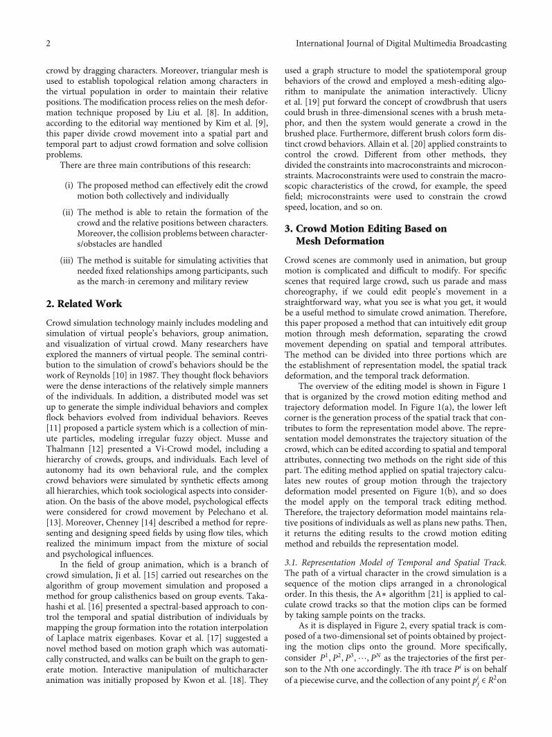
The overview of the editing model is shown in Figure 1that is organized by the crowd motion editing method andtrajectory deformation model. In Figure 1(a), the lower leftcorner is the generation process of the spatial track that con-tributes to form the representation model above. The repre-sentation model demonstrates the trajectory situation of thecrowd, which can be edited according to spatial and temporalattributes, connecting two methods on the right side of thispart. The editing method applied on spatial trajectory calcu-lates new routes of group motion through the trajectorydeformation model presented on Figure 1(b), and so doesthe model apply on the temporal track editing method.Therefore, the trajectory deformation model maintains rela-tive positions of individuals as well as plans new paths. Then,it returns the editing results to the crowd motion editingmethod and rebuilds the representation model.
3.1. Representation Model of Temporal and Spatial Track.The path of a virtual character in the crowd simulation is asequence of the motion clips arranged in a chronologicalorder. In this thesis, the A∗ algorithm [21] is applied to cal-culate crowd tracks so that the motion clips can be formedby taking sample points on the tracks.
As it is displayed in Figure 2, every spatial track is com-posed of a two-dimensional set of points obtained by project-ing the motion clips onto the ground. More specifically,consider P1, P2, P3,⋯, PN as the trajectories of the first per-son to the Nth one accordingly. The ith trace Pi is on behalfof a piecewise curve, and the collection of any point pij ∈ R
2on
2 International Journal of Digital Multimedia Broadcasting
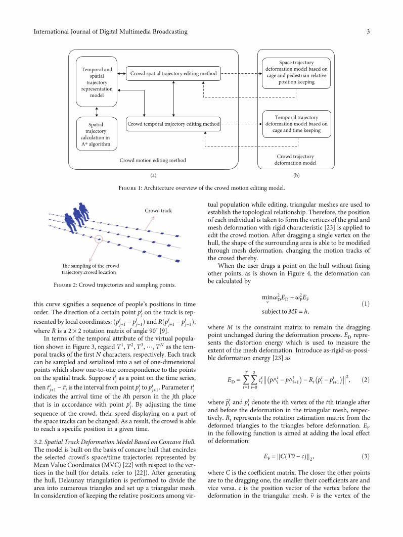
this curve signifies a sequence of people’s positions in timeorder. The direction of a certain point pij on the track is rep-
resented by local coordinates: ðpij+1 − pij−1Þ and Rðpij+1 − pij−1Þ,where R is a 2 × 2 rotation matrix of angle 90° [9].
In terms of the temporal attribute of the virtual popula-tion shown in Figure 3, regard T1, T2, T3,⋯, TN as the tem-poral tracks of the first N characters, respectively. Each trackcan be sampled and serialized into a set of one-dimensionalpoints which show one-to-one correspondence to the pointson the spatial track. Suppose tij as a point on the time series,
then tij+1 − tij is the interval from point pij to pij+1. Parameter tij
indicates the arrival time of the ith person in the jth placethat is in accordance with point pij. By adjusting the timesequence of the crowd, their speed displaying on a part ofthe space tracks can be changed. As a result, the crowd is ableto reach a specific position in a given time.
3.2. Spatial Track DeformationModel Based on Concave Hull.The model is built on the basis of concave hull that encirclesthe selected crowd’s space/time trajectories represented byMean Value Coordinates (MVC) [22] with respect to the ver-tices in the hull (for details, refer to [22]). After generatingthe hull, Delaunay triangulation is performed to divide thearea into numerous triangles and set up a triangular mesh.In consideration of keeping the relative positions among vir-
tual population while editing, triangular meshes are used toestablish the topological relationship. Therefore, the positionof each individual is taken to form the vertices of the grid andmesh deformation with rigid characteristic [23] is applied toedit the crowd motion. After dragging a single vertex on thehull, the shape of the surrounding area is able to be modifiedthrough mesh deformation, changing the motion tracks ofthe crowd thereby.
When the user drags a point on the hull without fixingother points, as is shown in Figure 4, the deformation canbe calculated by
minv
ω2DED + ω2
FEF
subject toMv = h,ð1Þ
where M is the constraint matrix to remain the draggingpoint unchanged during the deformation process. ED repre-sents the distortion energy which is used to measure theextent of the mesh deformation. Introduce as-rigid-as-possi-ble deformation energy [23] as
ED = 〠T
t=1〠2
i=0cti p∧t
i − p∧ti+1
� �− Rt pti − pti+1
� ��� ��2, ð2Þ
where pti and pti denote the ith vertex of the tth triangle afterand before the deformation in the triangular mesh, respec-tively. Rt represents the rotation estimation matrix from thedeformed triangles to the triangles before deformation. EFin the following function is aimed at adding the local effectof deformation:
EF = C Tv − cð Þk k2, ð3Þ
where C is the coefficient matrix. The closer the other pointsare to the dragging one, the smaller their coefficients are andvice versa. c is the position vector of the vertex before thedeformation in the triangular mesh. v is the vertex of the
Crowd spatial trajectory editing method
Crowd trajectorydeformation model
Crowd temporal trajectory editing method
Crowd motion editing method
(a) (b)
Temporal andspatial
trajectoryrepresentation
model
Temporal trajectorydeformation model based on
cage and time keeping
Space trajectorydeformation model based oncage and pedestrian relative
position keeping
Spatialtrajectory
calculation in A⁎ algorithm
Figure 1: Architecture overview of the crowd motion editing model.
The sampling of the crowd trajectory:crowd location
Crowd track
Figure 2: Crowd trajectories and sampling points.
3International Journal of Digital Multimedia Broadcasting
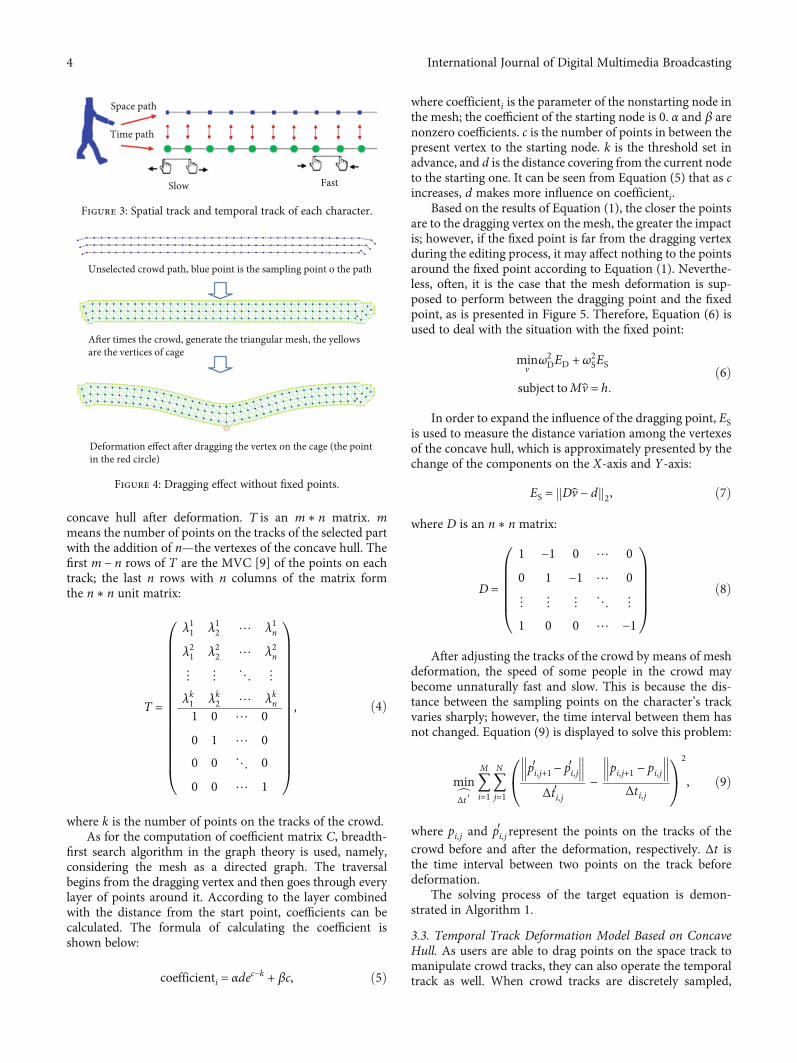
concave hull after deformation. T is an m ∗ n matrix. mmeans the number of points on the tracks of the selected partwith the addition of n—the vertexes of the concave hull. Thefirst m − n rows of T are the MVC [9] of the points on eachtrack; the last n rows with n columns of the matrix formthe n ∗ n unit matrix:
T =
λ11 λ12
λ21 λ22
⋯ λ1n
⋯ λ2n
⋮ ⋮
λk1 λk2
⋱ ⋮
⋯ λkn1 0
0 1
⋯ 0
⋯ 0
0 0
0 0
⋱ 0
⋯ 1
0BBBBBBBBBBBBBBBB@
1CCCCCCCCCCCCCCCCA, ð4Þ
where k is the number of points on the tracks of the crowd.As for the computation of coefficient matrix C, breadth-
first search algorithm in the graph theory is used, namely,considering the mesh as a directed graph. The traversalbegins from the dragging vertex and then goes through everylayer of points around it. According to the layer combinedwith the distance from the start point, coefficients can becalculated. The formula of calculating the coefficient isshown below:
coefficienti = αdec−k + βc, ð5Þ
where coefficienti is the parameter of the nonstarting node inthe mesh; the coefficient of the starting node is 0. α and β arenonzero coefficients. c is the number of points in between thepresent vertex to the starting node. k is the threshold set inadvance, and d is the distance covering from the current nodeto the starting one. It can be seen from Equation (5) that as cincreases, d makes more influence on coefficienti.
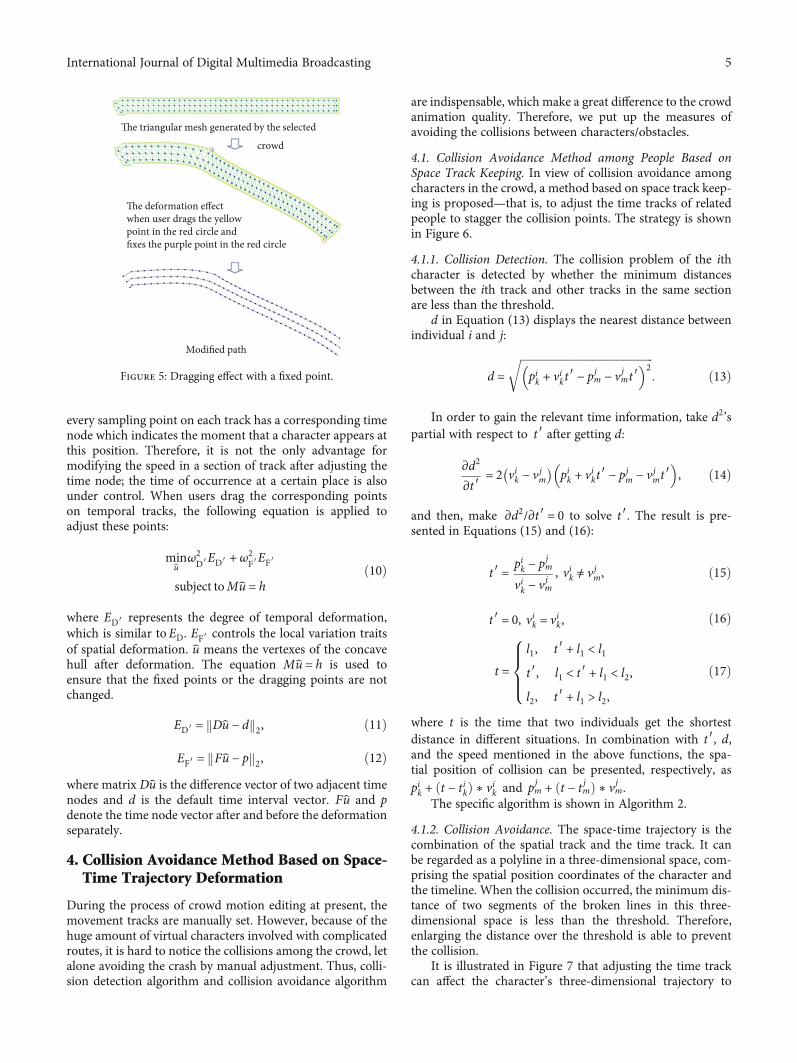
Based on the results of Equation (1), the closer the pointsare to the dragging vertex on the mesh, the greater the impactis; however, if the fixed point is far from the dragging vertexduring the editing process, it may affect nothing to the pointsaround the fixed point according to Equation (1). Neverthe-less, often, it is the case that the mesh deformation is sup-posed to perform between the dragging point and the fixedpoint, as is presented in Figure 5. Therefore, Equation (6) isused to deal with the situation with the fixed point:
minv
ω2DED + ω2
SES
subject toMv = h:ð6Þ
In order to expand the influence of the dragging point, ESis used to measure the distance variation among the vertexesof the concave hull, which is approximately presented by thechange of the components on the X-axis and Y-axis:
ES = Dv − dk k2, ð7Þ
where D is an n ∗ n matrix:
D =
1 −1 0 ⋯ 0
0 1 −1 ⋯ 0
⋮ ⋮ ⋮ ⋱ ⋮
1 0 0 ⋯ −1
0BBBBB@
1CCCCCA ð8Þ
After adjusting the tracks of the crowd by means of meshdeformation, the speed of some people in the crowd maybecome unnaturally fast and slow. This is because the dis-tance between the sampling points on the character’s trackvaries sharply; however, the time interval between them hasnot changed. Equation (9) is displayed to solve this problem:
mincΔt ′ 〠M
i=1〠N
j=1
pi,j+1′ − pi,j′��� ���
Δti,j′−
pi,j+1 − pi,j��� ���
Δti,j
0@ 1A2
, ð9Þ
where pi,j and pi,j′ represent the points on the tracks of thecrowd before and after the deformation, respectively. Δt isthe time interval between two points on the track beforedeformation.
The solving process of the target equation is demon-strated in Algorithm 1.
3.3. Temporal Track Deformation Model Based on ConcaveHull. As users are able to drag points on the space track tomanipulate crowd tracks, they can also operate the temporaltrack as well. When crowd tracks are discretely sampled,
Space path
Time path
Slow Fast
Figure 3: Spatial track and temporal track of each character.
Unselected crowd path, blue point is the sampling point o the path
After times the crowd, generate the triangular mesh, the yellowsare the vertices of cage
Deformation effect after dragging the vertex on the cage (the pointin the red circle)
Figure 4: Dragging effect without fixed points.
4 International Journal of Digital Multimedia Broadcasting
every sampling point on each track has a corresponding timenode which indicates the moment that a character appears atthis position. Therefore, it is not the only advantage formodifying the speed in a section of track after adjusting thetime node; the time of occurrence at a certain place is alsounder control. When users drag the corresponding pointson temporal tracks, the following equation is applied toadjust these points:
minu
ω2D′ED′ + ω2
F′EF′
subject toMu = hð10Þ
where ED′ represents the degree of temporal deformation,which is similar to ED. EF′ controls the local variation traitsof spatial deformation. u means the vertexes of the concavehull after deformation. The equation Mu = h is used toensure that the fixed points or the dragging points are notchanged.
ED′ = Du − dk k2, ð11Þ
EF′ = Fu − pk k2, ð12Þwhere matrix Du is the difference vector of two adjacent timenodes and d is the default time interval vector. Fu and pdenote the time node vector after and before the deformationseparately.
4. Collision Avoidance Method Based on Space-Time Trajectory Deformation
During the process of crowd motion editing at present, themovement tracks are manually set. However, because of thehuge amount of virtual characters involved with complicatedroutes, it is hard to notice the collisions among the crowd, letalone avoiding the crash by manual adjustment. Thus, colli-sion detection algorithm and collision avoidance algorithm
are indispensable, which make a great difference to the crowdanimation quality. Therefore, we put up the measures ofavoiding the collisions between characters/obstacles.
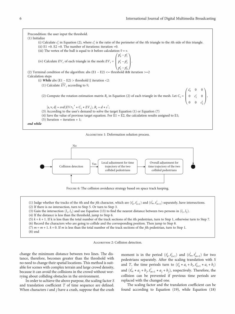
4.1. Collision Avoidance Method among People Based onSpace Track Keeping. In view of collision avoidance amongcharacters in the crowd, a method based on space track keep-ing is proposed—that is, to adjust the time tracks of relatedpeople to stagger the collision points. The strategy is shownin Figure 6.
4.1.1. Collision Detection. The collision problem of the ithcharacter is detected by whether the minimum distancesbetween the ith track and other tracks in the same sectionare less than the threshold.
d in Equation (13) displays the nearest distance betweenindividual i and j:
d =ffiffiffiffiffiffiffiffiffiffiffiffiffiffiffiffiffiffiffiffiffiffiffiffiffiffiffiffiffiffiffiffiffiffiffiffiffiffiffiffiffiffiffiffiffiffiffiffipik + vikt ′ − pjm − vjmt ′
� �2r
: ð13Þ
In order to gain the relevant time information, take d2’spartial with respect to t ′ after getting d:
∂d2
∂t ′= 2 vik − vjm
� �pik + vikt ′ − pjm − vjmt ′
� �, ð14Þ
and then, make ∂d2/∂t ′ = 0 to solve t ′. The result is pre-sented in Equations (15) and (16):
t ′ = pik − pjm
vik − vjm, vik ≠ vjm, ð15Þ
t ′ = 0, vik = vik, ð16Þ
t =l1, t ′ + l1 < l1
t ′, l1 < t ′ + l1 < l2,
l2, t ′ + l1 > l2,
8>><>>: ð17Þ
where t is the time that two individuals get the shortestdistance in different situations. In combination with t ′, d,and the speed mentioned in the above functions, the spa-tial position of collision can be presented, respectively, aspik + ðt − tikÞ ∗ vik and pjm + ðt − t jmÞ ∗ vjm.
The specific algorithm is shown in Algorithm 2.
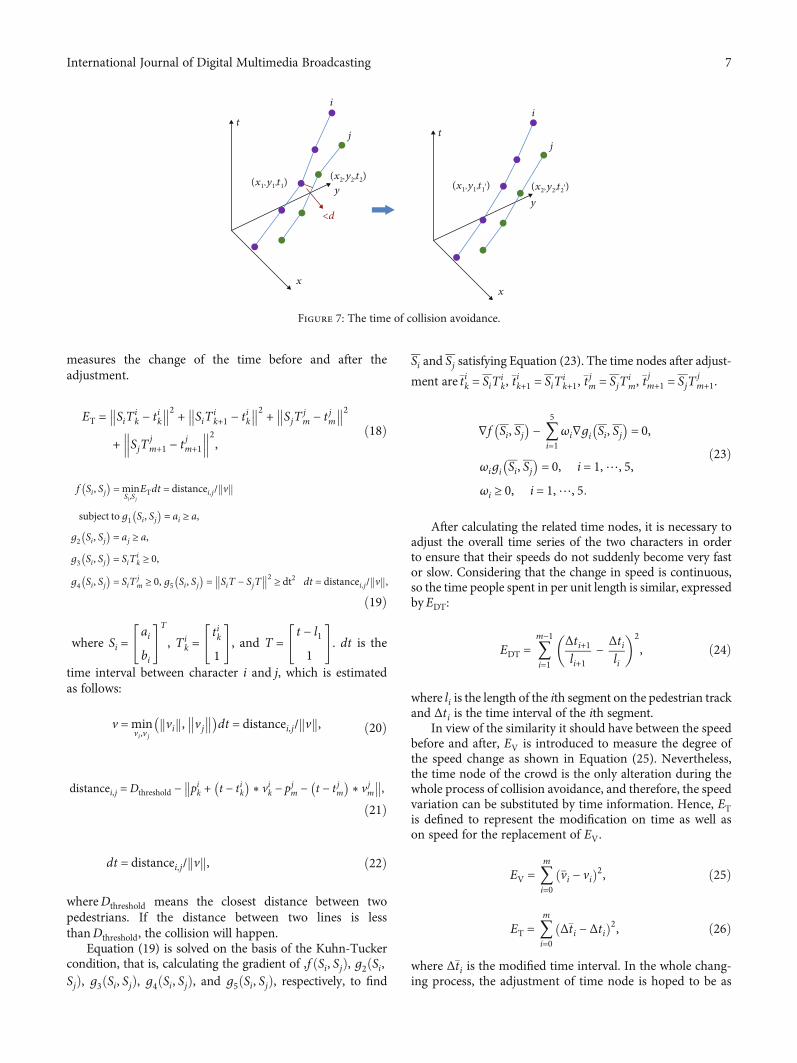
4.1.2. Collision Avoidance. The space-time trajectory is thecombination of the spatial track and the time track. It canbe regarded as a polyline in a three-dimensional space, com-prising the spatial position coordinates of the character andthe timeline. When the collision occurred, the minimum dis-tance of two segments of the broken lines in this three-dimensional space is less than the threshold. Therefore,enlarging the distance over the threshold is able to preventthe collision.
It is illustrated in Figure 7 that adjusting the time trackcan affect the character’s three-dimensional trajectory to
The triangular mesh generated by the selected
crowd
Modified path
The deformation effect when user drags the yellowpoint in the red circle andfixes the purple point in the red circle
Figure 5: Dragging effect with a fixed point.
5International Journal of Digital Multimedia Broadcasting
change the minimum distance between two lines. The dis-tance, therefore, becomes greater than the threshold withno need to change their spatial locations. This method is suit-able for scenes with complex terrain and large crowd density,because it can avoid the collisions in the crowd without wor-rying about colliding obstacles in the environment.
In order to achieve the above purpose, the scaling factor Sand translation coefficient T of time sequence are defined.When characters i and j have a crash, suppose that the crash
moment is in the period ðtik, tik+1Þ and ðt jm, t jm+1Þ for twopedestrians separately. After the scaling translation with Sand T , the time periods turn to ðtik ∗ ai + bi, tik+1 ∗ ai + biÞand ðt jm ∗ aj + bj, t
jm+1 ∗ aj + bjÞ, respectively. Therefore, the
collision can be prevented if previous time periods arereplaced with the changed one.
The scaling factor and the translation coefficient can befound according to Equation (19), while Equation (18)
Precondition: the user input the threshold.(1) Initialize
(i) Calculate cti in Equation (2), where cti is the ratio of the perimeter of the tth triangle to the ith side of this triangle.(ii) E1 =0. E2 =0. The number of iterations: iteration =0.(iii) The vertex of the hull is equal to it before calculation: v = v.
(iv) Calculate EVt of each triangle in the mesh: EVt =
pt0 − pt1
pt1 − pt2
pt2 − pt0
0BB@1CCA.
(2) Terminal condition of the algorithm: abs (E1 – E2) <= threshold && iteration >=2Calculation steps
(i) While abs (E1 – E2) > threshold || iteration <2:(1) Calculate dEV t according to v;
(2) Compute the rotation estimation matrix Rt in Equation (2) of each triangle in the mesh. Let Ct =
ct0 0 0
0 ct1 0
0 0 ct2
0BB@1CCA,
½s, v, d� = svdðEV∧t ′ ∗ Ct ∗ EVtÞ, Rt = d ∗ s′;(3) According to the user's demand to solve the target Equation (1) or Equation (7)(4) Save the value of previous target equation. For E1 = E2, the calculation results assigned to E1;(5) Iteration = iteration + 1;
end while
Algorithm 1: Deformation solution process.
Local adjustment for timetrajectory of the twocollided pedestrians
Overall adjustment fortime trajectory of the two
collided pedestrians
No
YesCollision detection
Figure 6: The collision avoidance strategy based on space track keeping.
(1) Judge whether the tracks of the ith and the jth character, which are ðtik, tik+1Þ and ðt jm, t jm+1Þ separately, have intersections.(2) If there is no intersection, turn to Step 5. Or turn to Step 3.(3) Gain the intersection ðl1, l2Þ and use Equation (13) to find the nearest distance between two persons in ðl1, l2Þ.(4) If the distance is less than the threshold, jump to Step 6.(5) k = k + 1. If k is less than the total number of the track sections of the ith pedestrian, turn to Step 1, otherwise turn to Step 7.(6) Record the characters who are going to collide and the corresponding position. Then jump to Step 8.(7) m =m + 1. k = 0. If m is less than the total number of the track sections of the jth pedestrian, turn to Step 1.(8) end
Algorithm 2: Collision detection.
6 International Journal of Digital Multimedia Broadcasting
measures the change of the time before and after theadjustment.
ET = SiTik − tik
�� ��2 + SiTik+1 − tik
�� ��2 + SjTjm − t jm
�� ��2+ SjT
jm+1 − t jm+1
��� ���2, ð18Þ
f Si, Sj� �
=minSi ,Sj
ETdt = distancei,j/ vk k
subject tog1 Si, Sj� �
= ai ≥ a,
g2 Si, Sj� �
= aj ≥ a,
g3 Si, Sj� �
= SiTik ≥ 0,
g4 Si, Sj� �
= SiTjm ≥ 0, g5 Si, Sj
� �= SiT − SjT�� ��2 ≥ dt2 dt = distancei,j/ vk k,
ð19Þ
where Si =ai
bi
" #T
, Tik =
tik
1
" #, and T =
t − l1
1
" #. dt is the
time interval between character i and j, which is estimatedas follows:
v =minvi ,v j
vik k, vj�� ��� �
dt = distancei,j/ vk k, ð20Þ
distancei,j =Dthreshold − pik + t − tik� �
∗ vik − pjm − t − t jm� �
∗ vjm�� ��,
ð21Þ
dt = distancei,j/ vk k, ð22Þ
whereDthreshold means the closest distance between twopedestrians. If the distance between two lines is lessthanDthreshold, the collision will happen.
Equation (19) is solved on the basis of the Kuhn-Tuckercondition, that is, calculating the gradient of ,f ðSi, SjÞ, g2ðSi,SjÞ, g3ðSi, SjÞ, g4ðSi, SjÞ, and g5ðSi, SjÞ, respectively, to find
Si and Sj satisfying Equation (23). The time nodes after adjust-
ment are�tik = SiTik, �t
ik+1 = SiT
ik+1, �t
jm = SjT
im, �t
jm+1 = SjT
jm+1.
∇f Si, Sj� �
− 〠5
i=1ωi∇gi Si, Sj
� �= 0,
ωigi Si, Sj� �
= 0, i = 1,⋯, 5,
ωi ≥ 0, i = 1,⋯, 5:
ð23Þ
After calculating the related time nodes, it is necessary toadjust the overall time series of the two characters in orderto ensure that their speeds do not suddenly become very fastor slow. Considering that the change in speed is continuous,so the time people spent in per unit length is similar, expressedbyEDT:
EDT = 〠m−1
i=1
Δti+1li+1
−Δtili
� 2, ð24Þ
where li is the length of the ith segment on the pedestrian trackand Δti is the time interval of the ith segment.
In view of the similarity it should have between the speedbefore and after, EV is introduced to measure the degree ofthe speed change as shown in Equation (25). Nevertheless,the time node of the crowd is the only alteration during thewhole process of collision avoidance, and therefore, the speedvariation can be substituted by time information. Hence, ETis defined to represent the modification on time as well ason speed for the replacement of EV.
EV = 〠m
i=0�vi − við Þ2, ð25Þ
ET = 〠m
i=0Δ�ti − Δtið Þ2, ð26Þ
where Δ�ti is the modified time interval. In the whole chang-ing process, the adjustment of time node is hoped to be as
i
tj
y
<d
x
(x1,y1,t1)(x2,y2,t2)
i
tj
y
x
(x1,y1,t1′) (x2,y2,t2′)
Figure 7: The time of collision avoidance.
7International Journal of Digital Multimedia Broadcasting
little as possible. As a result, ETP is going to measure thedegree of the change of time node as described in
ETP = 〠n
i=0
�ti − tið Þ2: ð27Þ
Associating with Equations (24), (26), and (27), theavoidance method can be demonstrated by an optimizationmodel, as shown in
min�t
α2EDT + β2ET + γ2ETP
subject toMS ∗�t =mt,ð28Þ
where α,β, and γ are the weight coefficients of EDT, ET, andETP, respectively. The function of the matrix MS is to filterout the time nodes adjusted by Equation (18), while mt is acolumn vector consisting of the values of modified timenodes. The purpose of the constraint equation is to keepthe time points that have been changed in the collision avoid-ance process away from changing again when the whole timetrack is later modified.
The specific algorithm of collision avoidance method isshown in Algorithm 3.
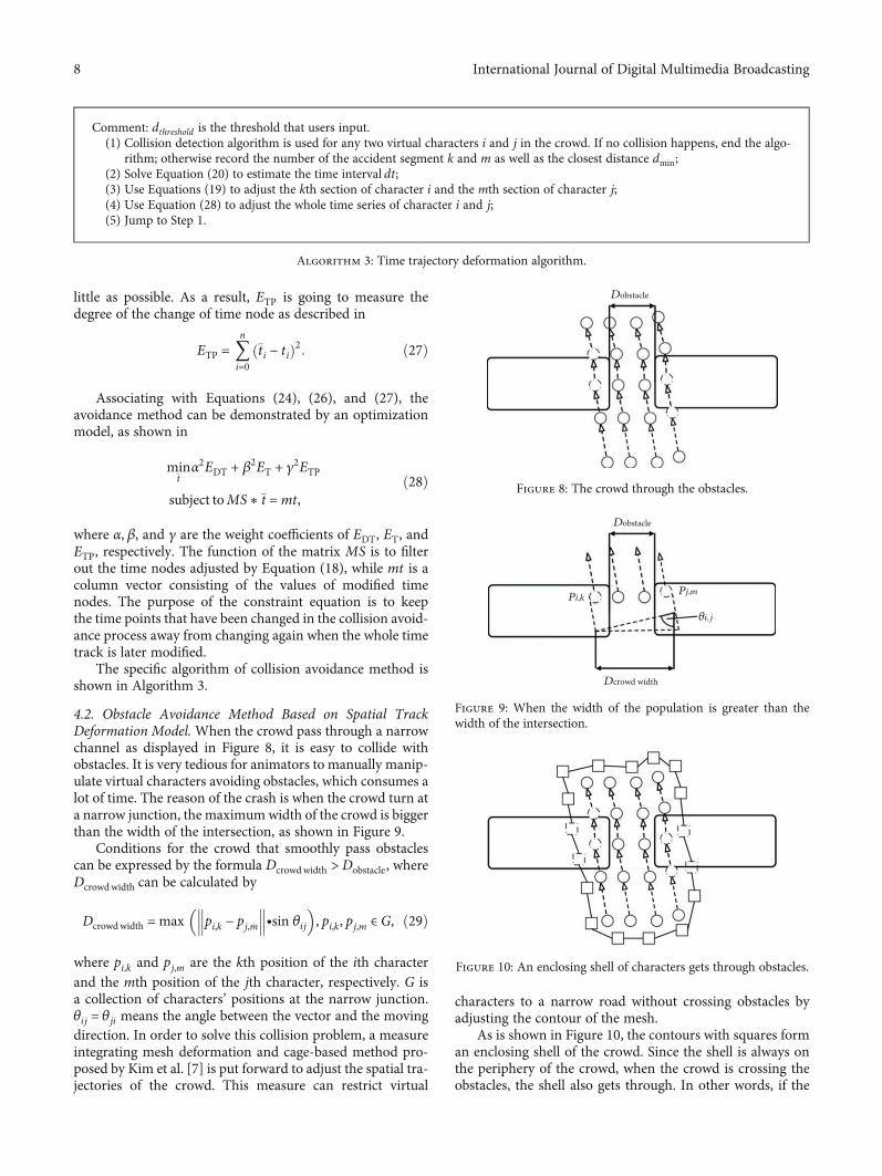
4.2. Obstacle Avoidance Method Based on Spatial TrackDeformation Model.When the crowd pass through a narrowchannel as displayed in Figure 8, it is easy to collide withobstacles. It is very tedious for animators to manually manip-ulate virtual characters avoiding obstacles, which consumes alot of time. The reason of the crash is when the crowd turn ata narrow junction, the maximumwidth of the crowd is biggerthan the width of the intersection, as shown in Figure 9.
Conditions for the crowd that smoothly pass obstaclescan be expressed by the formula Dcrowdwidth >Dobstacle, whereDcrowdwidth can be calculated by
Dcrowdwidth = max pi,k − pj,m��� ���∙sin θij
� �, pi,k, pj,m ∈G, ð29Þ
where pi,k and pj,m are the kth position of the ith characterand the mth position of the jth character, respectively. G isa collection of characters’ positions at the narrow junction.θij = θji means the angle between the vector and the movingdirection. In order to solve this collision problem, a measureintegrating mesh deformation and cage-based method pro-posed by Kim et al. [7] is put forward to adjust the spatial tra-jectories of the crowd. This measure can restrict virtual
characters to a narrow road without crossing obstacles byadjusting the contour of the mesh.
As is shown in Figure 10, the contours with squares forman enclosing shell of the crowd. Since the shell is always onthe periphery of the crowd, when the crowd is crossing theobstacles, the shell also gets through. In other words, if the
Comment: dthreshold is the threshold that users input.(1) Collision detection algorithm is used for any two virtual characters i and j in the crowd. If no collision happens, end the algo-
rithm; otherwise record the number of the accident segment k and m as well as the closest distance dmin;(2) Solve Equation (20) to estimate the time interval dt;(3) Use Equations (19) to adjust the kth section of character i and the mth section of character j;(4) Use Equation (28) to adjust the whole time series of character i and j;(5) Jump to Step 1.
Algorithm 3: Time trajectory deformation algorithm.
Dobstacle
Figure 8: The crowd through the obstacles.
Dobstacle
Dcrowd width
Pj,mPi,k
𝜃i,j
Figure 9: When the width of the population is greater than thewidth of the intersection.
Figure 10: An enclosing shell of characters gets through obstacles.
8 International Journal of Digital Multimedia Broadcasting
shell has no intersection with barriers on the route, charac-ters in the shell will not touch the barriers, too.
Thus, adjusting the squares on the contour line of theshell to move them out of the obstacles can effectively avoidthe crash, so that the crowd will not get through the obstacles.The schematic diagram of adjusting the bounding shell ispresented in Figure 11, where the squares are the vertices ofthe shell and the circular points are the mapping points ofthe vertices inside the obstacles.
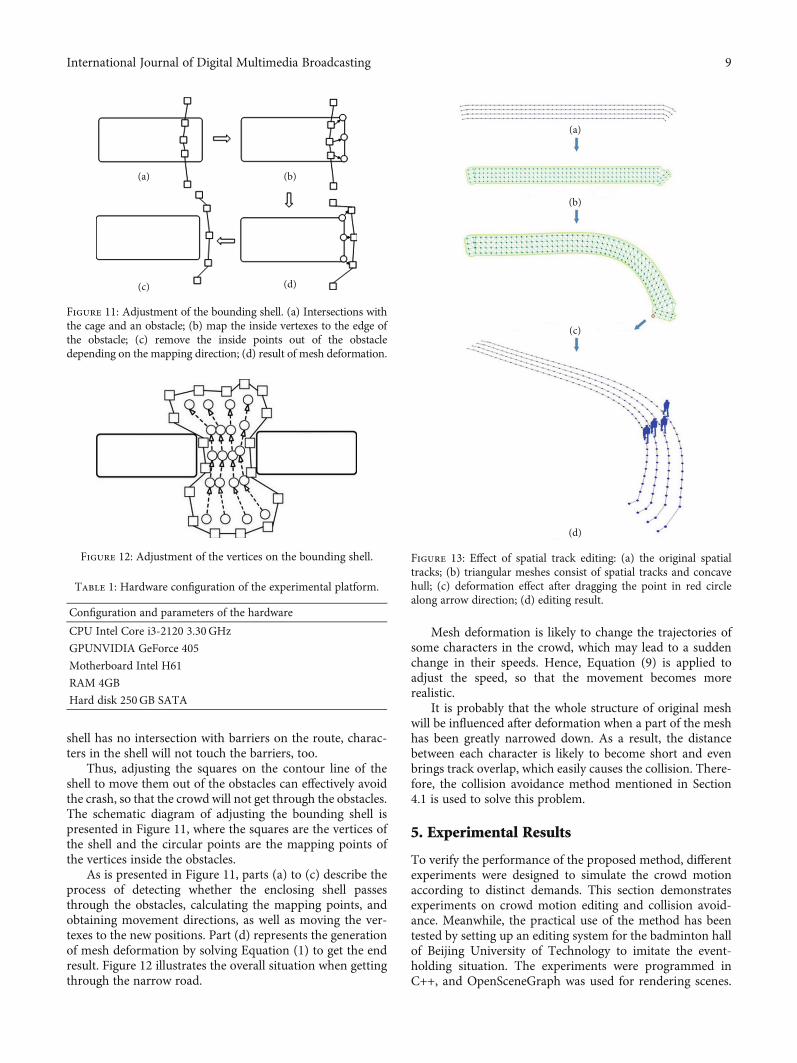
As is presented in Figure 11, parts (a) to (c) describe theprocess of detecting whether the enclosing shell passesthrough the obstacles, calculating the mapping points, andobtaining movement directions, as well as moving the ver-texes to the new positions. Part (d) represents the generationof mesh deformation by solving Equation (1) to get the endresult. Figure 12 illustrates the overall situation when gettingthrough the narrow road.
Mesh deformation is likely to change the trajectories ofsome characters in the crowd, which may lead to a suddenchange in their speeds. Hence, Equation (9) is applied toadjust the speed, so that the movement becomes morerealistic.
It is probably that the whole structure of original meshwill be influenced after deformation when a part of the meshhas been greatly narrowed down. As a result, the distancebetween each character is likely to become short and evenbrings track overlap, which easily causes the collision. There-fore, the collision avoidance method mentioned in Section4.1 is used to solve this problem.
5. Experimental Results
To verify the performance of the proposed method, differentexperiments were designed to simulate the crowd motionaccording to distinct demands. This section demonstratesexperiments on crowd motion editing and collision avoid-ance. Meanwhile, the practical use of the method has beentested by setting up an editing system for the badminton hallof Beijing University of Technology to imitate the event-holding situation. The experiments were programmed inC++, and OpenSceneGraph was used for rendering scenes.
(a)
(c)
(b)
(d)
Figure 11: Adjustment of the bounding shell. (a) Intersections withthe cage and an obstacle; (b) map the inside vertexes to the edge ofthe obstacle; (c) remove the inside points out of the obstacledepending on the mapping direction; (d) result of mesh deformation.
Figure 12: Adjustment of the vertices on the bounding shell.
Table 1: Hardware configuration of the experimental platform.
Configuration and parameters of the hardware
CPU Intel Core i3-2120 3.30GHz
GPUNVIDIA GeForce 405
Motherboard Intel H61
RAM 4GB
Hard disk 250GB SATA
(a)
(b)
(c)
(d)
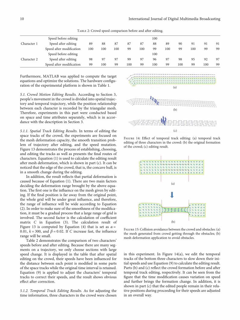
Figure 13: Effect of spatial track editing: (a) the original spatialtracks; (b) triangular meshes consist of spatial tracks and concavehull; (c) deformation effect after dragging the point in red circlealong arrow direction; (d) editing result.
9International Journal of Digital Multimedia Broadcasting
Furthermore, MATLAB was applied to compute the targetequations and optimize the solutions. The hardware configu-ration of the experimental platform is shown in Table 1.
5.1. Crowd Motion Editing Results. According to Section 3,people’s movement in the crowd is divided into spatial trajec-tory and temporal trajectory, while the position relationshipbetween each character is recorded by the triangular mesh.Therefore, experiments in this part were conducted basedon space and time attributes separately, which is in accor-dance with the description in Section 3.
5.1.1. Spatial Track Editing Results. In terms of editing thespace tracks of the crowd, the experiments are focused onthe mesh deformation capacity, the smooth transition prob-lem of trajectory after editing, and the speed mutation.Figure 13 demonstrates the process of establishing, choosing,and editing the tracks as well as presents the final routes ofcharacters. Equation (1) is used to calculate the editing resultafter mesh deformation, which is shown in part (c). It can benoticed that the edge of the crowd, that is, the concave hull, isin a smooth change during the editing.
In addition, the result reflects that partial deformation iscaused because of Equation (1). There are two main factorsdeciding the deformation range brought by the above equa-tion. The first one is the influence on the mesh given by edit-ing. If the final position is far away from the original point,the whole grid will be under great influence, and therefore,the range of influence will be wide according to Equation(2). In order to make sure of the smoothness of the modifica-tion, it must be a gradual process that a large range of grid isinvolved. The second factor is the calculation of coefficientmatrix C in Equation (3). The calculation result ofFigure 13 is computed by Equation (4) that is set as α =0:01, k = 300, and β = 0:02. If C increase fast, the influencerange will be small.
Table 2 demonstrates the comparison of two characters’speeds before and after editing. Because there are many seg-ments on a trajectory, we only choose sections with largespeed change. It is displayed in the table that after spatialediting on the crowd, their speeds have been influenced forthe distance between each point is modified in some partsof the space tracks while the original time interval is retained.Equation (9) is applied to adjust the characters’ temporaltracks to correct their speeds, and the result shows obviouseffect after correction.
5.1.2. Temporal Track Editing Results. As for adjusting thetime information, three characters in the crowd were chosen
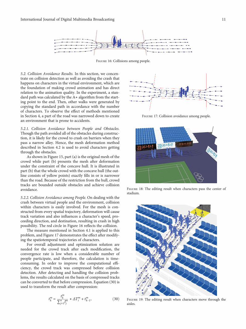
in this experiment. In Figure 14(a), we edit the temporaltracks of the bottom three characters to slow down their ini-tial speeds and use Equation (9) to calculate the editing result.Parts (b) and (c) reflect the crowd formation before and aftertemporal track editing, respectively. It can be seen from thefigure that the time modification causes variation on speedand further brings the formation change. In addition, it isshown in part (c) that the edited people remain in their rela-tive positions during proceeding for their speeds are adjustedin an overall way.
Table 2: Crowd speed comparison before and after editing.
Character 1
Speed before editing 100
Speed after editing 89 88 87 87 87 88 89 90 91 91 91
Speed after modification 100 100 100 99 100 99 100 99 100 99 99
Character 2
Speed before editing 100
Speed after editing 98 97 97 99 97 96 97 98 95 92 97
Speed after modification 99 100 99 100 99 100 99 100 99 100 99
(a)
(b)
(c)
Figure 14: Effect of temporal track editing: (a) temporal trackediting of three characters in the crowd: (b) the original formationof the crowd; (c) editing result.
(a)
(b)
Figure 15: Collision avoidance between the crowd and obstacles: (a)the mesh generated from crowd getting through the obstacles; (b)mesh deformation application to avoid obstacles.
10 International Journal of Digital Multimedia Broadcasting
5.2. Collision Avoidance Results. In this section, we concen-trate on collision detection as well as avoiding the crash thathappens on characters in the virtual environment, which arethe foundation of making crowd animation and has directrelation to the animation quality. In the experiment, a stan-dard path was calculated by the A∗ algorithm from the start-ing point to the end. Then, other walks were generated bycopying the standard path in accordance with the numberof characters. To observe the effect of methods mentionedin Section 4, a part of the road was narrowed down to createan environment that is prone to accidents.
5.2.1. Collision Avoidance between People and Obstacles.Though the path avoided all of the obstacles during construc-tion, it is likely for the crowd to crash on barriers when theypass a narrow alley. Hence, the mesh deformation methoddescribed in Section 4.2 is used to avoid characters gettingthrough the obstacles.
As shown in Figure 15, part (a) is the original mesh of thecrowd while part (b) presents the mesh after deformationunder the constraint of the concave hull. It is illustrated inpart (b) that the whole crowd with the concave hull (the out-line consists of yellow points) exactly fills in or is narrowerthan the road. Because of the restriction from the hull, crowdtracks are bounded outside obstacles and achieve collisionavoidance.
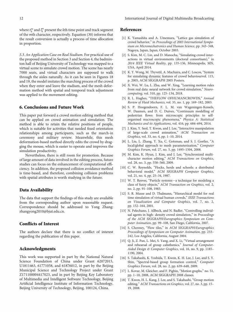
5.2.2. Collision Avoidance among People. On dealing with thecrash between virtual people and the environment, collisionwithin characters is easily involved. For the mesh is con-structed from every spatial trajectory, deformation will causetrack variation and also influences a character’s speed, pro-ceeding direction, and destination, resulting in crash in highpossibility. The red circle in Figure 16 reflects the collision.
The measure mentioned in Section 4.1 is applied to thisproblem, and Figure 17 demonstrates the effect after modify-ing the spatiotemporal trajectories of characters.
For overall adjustment and optimization solution areneeded for the crowd track after each modification, theconvergence rate is low when a considerable number ofpeople participate, and therefore, the calculation is time-consuming. In order to improve the computational effi-ciency, the crowd track was compressed before collisiondetection. After detecting and handling the collision prob-lems, the results calculated on the basis of compressed trackscan be converted to that before compression. Equation (30) isused to transform the result after compression:
tmk = tmk∑n
j=1lmj
∗ ΔTmi + tmk−1, ð30Þ
Figure 16: Collisions among people.
Figure 17: Collision avoidance among people.
Figure 18: The editing result when characters pass the center ofstadium.
Figure 19: The editing result when characters move through theaisles.
11International Journal of Digital Multimedia Broadcasting
where tmk and lmk present the kth time point and track segmentof themth character, respectively. Equation (30) informs thatthe result conversion is actually a process of time allocationin proportion.
5.3. An Application Case on Real Stadium. For practical use ofthe proposed method in Section 3 and Section 4, the badmin-ton hall of Beijing University of Technology was mapped to avirtual scene to simulate crowd motion. The scene has nearly7000 seats, and virtual characters are supposed to walkthrough the aisles naturally. As it can be seen in Figures 18and 19, the model imitates the marching process of the crowdwhen they enter and leave the stadium, and the mesh defor-mation method with spatial and temporal track adjustmentwas applied to the movement editing.
6. Conclusions and Future Work
This paper put forward a crowd motion editing method thatcan be applied on crowd animation and simulation. Themethod is able to retain the relative positions of people,which is suitable for activities that needed fixed orientationrelationships among participants, such as the march-inceremony and military review. Meanwhile, this meshdeformation-based method directly edits the crowd by drag-ging the mouse, which is easier to operate and improves thesimulation productivity.
Nevertheless, there is still room for promotion. Becauseof large amount of data involved in the editing process, futurestudies can focus on the enhancement of computational effi-ciency. In addition, the proposed collision avoidance methodis time-based, and therefore, combining collision problemswith spatial attributes is worth studying in the future.
Data Availability
The data that support the findings of this study are availablefrom the corresponding author upon reasonable request.Correspondence should be addressed to Yong Zhang:[email protected].
Conflicts of Interest
The authors declare that there is no conflict of interestregarding the publication of this paper.
Acknowledgments
This work was supported in part by the National NaturalScience Foundation of China under Grant 62072015,U1811463, 61771058, and 61876012, in part by the BeijingMunicipal Science and Technology Project under GrantZ171100004417023, and in part by Beijing Key Laboratoryof Multimedia and Intelligent Software Technology, BeijingArtificial Intelligence Institute of Information Technology,Beijing University of Technology, Beijing, 100124, China.
References
[1] K. Yamashita and A. Umemura, “Lattice gas simulation ofcrowd behavior,” in Proceedings of 2003 International Sympo-sium on Micromechatronics and Human Science, pp. 343–348,Nagoya, Japan, Japan, October 2003.
[2] S. Kim, M. C. Lin, and D. Manocha, “Simulating crowd inter-actions in virtual environments (doctoral consortium),” in2014 IEEE Virtual Reality, pp. 135-136, Minneapolis, MN,USA, April 2014.
[3] K. Y. Wong, M. Thyvetil, A. Machaira, and C. Loscos, “Systemfor simulating dynamic features of crowd behaviourvol. 115,p. 2005, ACM SIGGRAPH 2005 Posters.
[4] X. Wei, W. Lu, L. Zhu, and W. Xing, “Learning motion rulesfrom real data: neural network for crowd simulation,” Neuro-computing, vol. 310, pp. 125–134, 2018.
[5] R. L. Hughes, “THEFLOW OFHUMANCROWDS,” AnnualReview of Fluid Mechanics, vol. 35, no. 1, pp. 169–182, 2003.
[6] S. P. Hoogendoorn, F. L. M. van Wageningen-Kessels,W. Daamen, and D. C. Duives, “Continuum modelling ofpedestrian flows: from microscopic principles to self-organised macroscopic phenomena,” Physica A: StatisticalMechanics and its Applications, vol. 416, pp. 684–694, 2014.
[7] J. Kim, Y. Seol, T. Kwon, and J. Lee, “Interactive manipulationof large-scale crowd animation,” ACM Transaction onGraphics, vol. 33, no. 4, pp. 1–10, 2014.
[8] L. Liu, L. Zhang, Y. Xu, C. Gotsman, and S. J. Gortler, “Alocal/global approach to mesh parameterization,” ComputerGraphics Forum, vol. 27, no. 5, pp. 1495–1504, 2008.
[9] M. Kim, K. Hyun, J. Kim, and J. Lee, “Synchronized multi-character motion editing,” ACM Transactions on Graphics,vol. 28, no. 3, pp. 558–560, 2009.
[10] C. W. Reynolds, “Flocks, herds and schools: a distributedbehavioral model,” ACM SIGGRAPH Computer Graphics,vol. 21, no. 4, pp. 25–34, 1987.
[11] W. T. Reeves, “Particle systems—a technique for modeling aclass of fuzzy objects,” ACM Transaction on Graphics, vol. 2,no. 2, pp. 91–108, 1983.
[12] S. R. Musse and D. Thalmann, “Hierarchical model for realtime simulation of virtual human crowds,” IEEE Transactionson Visualization and Computer Graphics, vol. 7, no. 2,pp. 152–164, 2001.
[13] N. Pelechano, J. Allbeck, and N. Badler, “Controlling individ-ual agents in high- density crowd simulation,” in Proceedingsof the ACM SIGGRAPH/Eurographics Symposium on Com-puter Animation, pp. 99–108, San Diego, California, 2007.
[14] S. Chenney, “Flow tiles,” in ACM SIGGRAPH/EurographicsProceedings of Symposium on Computer Animation, pp. 233–242, Los Angeles, California, August 2004.
[15] Q. Ji, Z. Pan, L. Mei, S. Yang, and X. Li, “Virtual arrangementand rehearsal of group calisthenics,” Journal of Computer-Aided Design & Computer Graphics, vol. 16, no. 9, pp. 1185–1190, 2004.
[16] S. Takahashi, K. Yoshida, T. Kwon, K. H. Lee, J. Lee, and S. Y.Shin, “Spectral-based group formation control,” ComputerGraphics Forum, vol. 28, no. 2, pp. 639–648, 2009.
[17] L. Kovar, M. Gleicher, and F. Pighin, “Motion graphs,” no. 51,pp. 1–10, 2008, ACM SIGGRAPH 2008 classes.
[18] T. Kwon, H. L. Kang, J. Lee, and S. Takahashi, “Group motionediting,” ACM Transactions on Graphics, vol. 27, no. 3, pp. 15–19, 2008.
12 International Journal of Digital Multimedia Broadcasting
[19] B. Ulicny, P. D. Ciechomski, and D. Thalmann, “Crowdbrush:interactive authoring of real-time crowd scenes,” in Proceed-ings of the 2004 ACM SIGGRAPH/Eurographics symposiumon Computer animation, pp. 243–252, Los Angeles, California,August 2004.
[20] P. Allain, N. Courty, and T. Corpetti, “Optimal crowd editing,”Graphical Models, vol. 76, no. 1, pp. 1–16, 2014.
[21] D. Sharma and S. K. Dubey, “Anytime A∗ algorithm-an exten-sion to A∗ algorithm,” International Journal of Scientific &Engineering Research, vol. 4, no. 1, pp. 1–4, 2013.
[22] M. S. Floater, “Mean value coordinates,” Computer Aided Geo-metric Design, vol. 20, no. 1, pp. 19–27, 2003.
[23] T. Igarashi, T. Moscovich, and J. F. Hughes, “As-rigid-as-pos-sible shape manipulation,” ACM Transactions on Graphics,vol. 24, no. 3, pp. 1134–1141, 2005.
13International Journal of Digital Multimedia Broadcasting