research article efficient mac protocol for hybrid...
TRANSCRIPT
Research ArticleEfficient MAC Protocol for Hybrid Wireless Network withHeterogeneous Sensor Nodes
Md. Nasre Alam and Young-Chon Kim
Division of Electronics and Information Engineering, Chonbuk National University, Jeonju 561-756, Republic of Korea
Correspondence should be addressed to Young-Chon Kim; [email protected]
Received 22 July 2015; Accepted 7 February 2016
Academic Editor: Stefania Campopiano
Copyright © 2016 Md. N. Alam and Y.-C. Kim.This is an open access article distributed under the Creative Commons AttributionLicense, which permits unrestricted use, distribution, and reproduction in any medium, provided the original work is properlycited.
Although several DirectionalMediumAccess Control (DMAC) protocols have been designed for use with homogeneous networks,it can take a substantial amount of time to change sensor nodes that are equipped with an omnidirectional antenna for sensor nodeswith a directional antenna. Thus, we require a novel MAC protocol for use with an intermediate wireless network that consistsof heterogeneous sensor nodes equipped with either an omnidirectional antenna or a directional antenna. The MAC protocolsthat have been designed for use in homogeneous networks are not suitable for use in a hybrid network due to deaf, hidden, andexposed nodes. Therefore, we propose a MAC protocol that exploits the characteristics of a directional antenna and can also workefficiently with omnidirectional nodes in a hybrid network. In order to address the deaf, hidden, and exposed node problems, wedefine RTS/CTS for the neighbor (RTSN/CTSN) andNeighbor Information (NIP) packets.The performance of the proposedMACprotocol is evaluated through a numerical analysis using a Markov model. In addition, the analytical results of the MAC protocolare verified through an OPNET simulation.
1. Introduction
In wireless networks, directional antennas can be used toachieve a higher spatial reuse and, thus, a higher networkthroughput. Several MAC protocols have been proposedfor use with a directional antenna in wireless networks,and these protocols assume that all nodes in the networkhave homogenous antennas [1–5]. However, it is difficult inpractice to replace all of the sensor nodes that are equippedwith an isotropic antenna with sensor nodes with a direc-tional antenna. Thus, we should consider an intermediatewireless network that consists of heterogeneous nodes thatare equipped with either an omnidirectional antenna or adirectional antenna, and we refer to such a network as ahybrid network. However, existing MAC protocols are notsuitable for use in hybrid networks because these protocolswere originally designed for use in homogenous networks.The lack of appropriate MAC protocols for use in hybridnetworks results in serious issues related to deafness, hiddenterminals, and exposed nodes.The overall performance of thenetwork may deteriorate beyond that of an omnidirectional
network [6]. Therefore, we need to design a heterogeneity-aware directional MAC protocol that works efficiently withdirectional as well as omnidirectional nodes [7].
The use of a directional antenna in a wireless networkreduces the number of nodes that are blocked and achievesa higher spatial reuse. However, the Directional MediumAccess Control (DMAC) protocol faces several challengesin the presence of deaf nodes, hidden nodes, and exposednodes [3–5, 7, 8], and these problems are more severe with ahybrid network. Hidden and exposed nodes are located nearthe source node and may not hear the transmission from thesource.Therefore, theymay initiate a transmission that resultsin a collision.
In this paper, we propose aMACprotocol that is designedfor use in a hybrid network that works efficiently with hetero-geneous sensor nodes in the network. The characteristics ofa directional antenna are exploited, and the MAC protocolis also compatible with nodes equipped with a traditionalomnidirectional antenna. The protocol helps for improvingthe throughput of the hybrid network by minimizing thenegative impact of the deaf nodes, hidden nodes, and exposed
Hindawi Publishing CorporationJournal of SensorsVolume 2016, Article ID 7951965, 16 pageshttp://dx.doi.org/10.1155/2016/7951965
2 Journal of Sensors
AB
C
S R
(a)
XR S
(b)
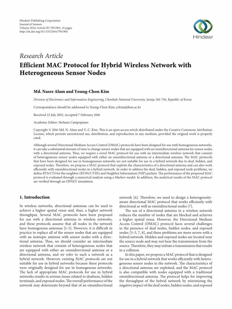
Figure 1: Issues with a directional antenna: (a) hidden node problem and (b) deaf node problem.
nodes.The protocol uses a concurrent RTS/CTS forNeighbor(RTSN/CTSN) transmission scheme after the channel hasbeen reserved by directional communicating nodes to makea neighbor aware of the imminent communication, whichminimizes the deaf node problem. The transmission of theNeighbor Information Packet (NIP) by the over hearer idlenodes minimizes the hidden node problem. Moreover, weproposed a scheme to set the Network Allocation Vectors(NAV) by the omnidirectional nodes to minimize exposednode problems in the network. Finally, we evaluate theproposed MAC protocol through a numerical analysis usinga Markov model. We focus on evaluating the performance ofour proposed MAC with the assumption that ideal channelcircumstances and a fixed number of nodes are observed inthe network. A simulation is conducted using the OPNETsimulator to validate the accuracy of the results.
The rest of this paper is organized as follows. We presentthe related work in the following section. Section 3 describestheMACprotocol that is herein proposed. Section 4 providesa numerical analysis of the proposed system. Section 5 dis-cusses the results of the performance for our proposedMAC,and we finally conclude the paper in Section 6.
2. Related Work
Several MAC protocols have been designed and analyzedfor use in wireless networks. In [9] a scheme is proposed totransmit Circular RTS (CRTS) in order to inform the entireneighborhood of future transmissions. Each node maintainsa location table for its neighbors, and the CTS is sentdirectionally (DCTS) towards an RTS originator. As a resultof the CRTS, the deafness and the hidden node problemsare reduced. However, DCTS still results in some deafnessand hidden node problems. In [10] the communicatingnodes transmit multiple control packets before the data istransmitted.The communicating nodes (sender and receiver)successively transmit multiple control packets, such as RTSandCTS, through all beams.Theneighbor of the nodes blockstheir corresponding beam after the control packet is heard.Since the control packets are transmitted around the senderand the receiver, the neighboring nodes become aware ofthe ongoing communication. In a similar manner, authorsin [5, 11, 12] proposed transmitting multiple control packetto the neighborhood before data communication. Although,there is little overhead due to the location table maintenanceand the transmission of multiple control packets, there is an
increase in the spatial reuse. However, the problems related todeaf, hidden, and exposed nodes are not completely solved.
Figure 1 shows an example of the hidden, exposed, anddeaf node problems that is described in [1, 3, 5, 7–9, 11, 13–15].In theory, a node that is located within the communicationrange of the receiving node and is out of the coverage range ofthe sender node can remain hidden and can cause a hiddennode problem. Figure 1(a) shows an example of the hiddennode problem.The𝐴, 𝐵, and𝐶 nodes are within the coveragerange of receiver 𝑅 but are out of the coverage range ofthe sender 𝑆. Therefore, the nodes may be hidden duringcommunication between the 𝑆 and 𝑅 nodes, which results ina hidden node problem.
In a hybrid network, the exposed node problem ismore severe than in a homogeneous network, and moreattention is needed [1, 7, 10, 16]. For example, if a nodewith an isotropic antenna transmits omnidirectional RTS(ORTS) and/or OCTS, the node with directional antennawill unnecessarily block the sectors that can be used for aconcurrent transmission. Therefore, the hidden and exposednode problems can severely degrade the performance of thenetwork [1].
A node fails to communicate with the intended receivernode when the node is communicating with a different node.For example, in Figure 1(b), node 𝑋 tries to communicatewith node 𝑆, but node 𝑆 is communicating with node 𝑅. Asa result, node 𝑆 is deaf with respect to node𝑋.
Instead of a transmission with multiple control packets,the scheme in [14, 15] uses communicating nodes that notifythe potential sender by sending additional control packets. Inthe scheme in [16], when a node finishes communication, aready-to-receive (RTR) frame is transmitted to the potentialsender. In the scheme in [15], when a communicating nodereceives RTS/CTS from other nodes, it transmits AdditionalRTS (A-RTS) to its potential sender.
In the schemes in [1, 3], the authors proposed a dualcarrier sensing scheme to address the hidden, exposed, anddeaf nodes. In the scheme in [1], the proposed DSDMACprotocol uses two well-separated wireless channels to trans-mit data and a busy tone. The data channel carries dataand control packets while the busy-tone channel is used totransmit a busy-tone sine-wave signal. On the data channel,the packet will transmit directionally while the packet willtransmit omnidirectionally on the busy-tone channel. In thescheme in [3], the author proposed a DA-MAC protocol thatalso uses two separate wireless channels to transmit the dataand control packets. In that scheme, the data and control
Journal of Sensors 3
(1) Procedure neighbor determination(2) if (node = omni)(3) if (hello packet receive)(4) nit.neighbor add = packet.add(5) nit.beam number = 0(6) nit.beam status = free(7) end if(8) else(9) transmit hello packet omni directional(10) end(11) end if(12) else(13) If (hello packet receive)(14) nit.neighbor add = packet.add(15) nit.beam number = packet.sector(16) nit.beam status = free(17) end if(18) else(19) transmit hello packet through all beams(20) end(21) end(22) end
Algorithm 1: Neighbor determination algorithm.
packet transmission is directional while the nodes listen tothe channel through all beams. After overhearing the packet,the neighbor nodes block the corresponding beam at the datachannel but continue listening at the control channel. If anode wants to communicate with another node that blocksthe data channel beam, the former replies with a DCTS at thecontrol channel. If the communicating nodes exchange RTSand CTS over both channels, then they can transmit data.
However, the previous schemes are only designed foruse with homogeneous networks and will not perform wellwhen used with hybrid networks [7]. In a hybrid network,the exposed node problem is more severe than that of ahomogeneous network.
3. The Proposed MAC
In this section, we discuss the detailed mechanism of theproposed MAC protocol. The basic concept, including inter-frame spacing, the binary backoff, and the congestionmecha-nism, is taken from the IEEE 802.11 Distributed CoordinationFunction (DCF) standard. The proposed MAC protocol isdesigned for use with a hybrid wireless network with twotypes of sensor nodes, including an (1) omnidirectional nodeequipped with an isotropic antenna and (2) a Directionalnode equipped with a Multibeam Smart Antenna (MBSA).TheMBSA can form𝑀 number of nonoverlapping beams tocover the entire 360∘ area around the node, and the beamsare pointed in a fixed direction. A packet can be transmittedor received concurrently by using all beams and can achievea higher range of transmission in all directions. Therefore, anode can transmit/receive packets through any/all of thesebeams.
The node in the network does not consider caching theAngle of Arrival (AoA) and the beam locking/unlocking fea-ture presented in traditional DMAC protocols. We maintainthe location table that contains the location of the one-hopneighbors in the Neighbor Information Table (NIT).
3.1. Neighbor Determination. In order to determine the loca-tion of the neighborhood, we use a gossip algorithm in whicha node sends a “hello packet” to its one-hop neighbors.Whena node receives the “hello packet” from the other nodes, itstores the neighbor’s address and the receiving sector numberin the NIT. When an omnidirectional node receives thepacket, it stores the neighbor’s address in the NIT and thebeam number field value will always be zero. Algorithm 1shows the algorithm that is used to determine the neighbor’slocation for the system model.
3.2. Channel Sensing. The omnidirectional nodes sense thechannel as traditional MAC protocols, and the directionalnode senses the channel through an MBSA that has 𝑀number of nonoverlapping beams fixed in different sectorsaround the node. The nodes that hear the transmissionthrough any of the beams set their Directional NetworkAllocation Vector (DNAV) and continue to sense the channelthrough the other beams.
3.3. Packet Transmission. The omnidirectional node trans-mits a packet by following the traditional approach of theIEEE 802.11 MAC protocol. A node simply transmits anomnidirectional packet, and if a directional node has apacket, it sends a Directional RTS (DRTS) only towardsthe destination node while the receiver node replies with a
4 Journal of Sensors
(1) Procedure Pkt Tx(2) if (node == omni)(3) Pkt.sector = 0(4) send Packet to antenna controller(5) else(6) 𝑖 = 0
(7) while (nit[𝑖].add NOT dest add)(8) 𝑖 = 𝑖 + 1
(9) end while(10) sector = nit[𝑖].sector(11) if (pkt = RTS)(12) RTS.sector = sector(13) send RTS to antenna controller(14) wait CTS timeout + SIFS(15) if (CTS received)(16) RTS.sector = 0(17) send RTS to antenna controller(18) else(19) Retransmit(20) else if (pkt = CTS)(21) CTS.sector = sector(22) send CTS to antenna controller(23) wait for SIFS time(24) CTS.secor = 0(25) send CTS to antenna controller(26) else(27) DATA/ACK.sector = sector(28) send DATA/ACK to antenna controller(29) End
Algorithm 2: Packet transmission algorithm.
Directional CTS (DCTS) only towards the sender node. Aftera successful DRTS/DCTS handshake, the communicatingnodes send RTSN and CTSN concurrently toward theirvicinity through other beams to inform the neighbors ofthe impending communication. Then the nodes start theDATA communication.The other beams of the communicat-ing nodes are blocked for the communication. Algorithm 2shows the algorithm to transmit the packet for our proposedMAC.
3.4. Packet Reception. The omnidirectional nodes follow thesame approach that is used in a traditional IEEE 802.11 MACprotocol, but setting the NAV is quite different. When adirectional node overhears the DRTS/DCTS/ORTS/OCTS,it sets NAV1. If the packet is RTSN/CTSN, then it setsNAV2. When a directional node receives DRTS, it replieswith a DCTS and waits for the CTS-timeout + SIFS period.Then, RTSN is transmitted to its vicinity after the SIFStime, and then data communication starts. The rest of thebeams are deactivated for transmission/reception duringcommunication. When a node overhears a packet, it setsDNAV for the receiving beam and continues channel sensingthrough other beams. Algorithm 3 depicts the algorithm thatis used to receive the packet in our system model.
3.5. NAV and DNAV. TheNetwork Allocation Vector (NAV)and the Directional Network Allocation Vector (DNAV)comprise the virtual carrier sensing mechanism that is usedwith the wireless network protocols. The NAV mechanismis used by the omnidirectional MAC protocols, and theDNAV is used by the directional MAC protocol. Since oursystem model is designed for hybrid network, we followboth the mechanisms for virtual carrier sensing. In oursystem model, the omnidirectional nodes follow the NAVmechanism, and the directional nodes follow the DNAVmechanism.
We proposed two types of NAV for the omnidirectionalnodes in the network: NAV1 and NAV2. When a nodeoverhears the RTS/CTS packet, it means the node is inthe same communication sector, and its transmission mayinterrupt ongoing communication. Therefore, the node setsNAV1 and defers the transmission until NAV1 does notexpire. When a node overhears RTSN/CTSN, it means thatthe node is not in the same communication sector, andits communication with other nodes will not interrupt theongoing communication. Therefore, it sets NAV2 and cancommunicate with other nodes in the network. Thus, weincrease the spatial reuse in the network by minimizing theexposed node problem.
Journal of Sensors 5
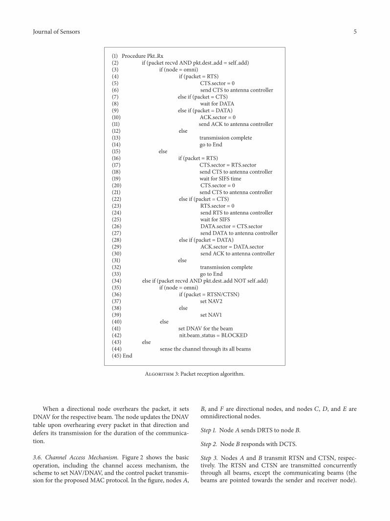
(1) Procedure Pkt Rx(2) if (packet recvd AND pkt.dest add = self add)(3) if (node = omni)(4) if (packet = RTS)(5) CTS.sector = 0(6) send CTS to antenna controller(7) else if (packet = CTS)(8) wait for DATA(9) else if (packet = DATA)(10) ACK.sector = 0(11) send ACK to antenna controller(12) else(13) transmission complete(14) go to End(15) else(16) if (packet = RTS)(17) CTS.sector = RTS.sector(18) send CTS to antenna controller(19) wait for SIFS time(20) CTS.sector = 0(21) send CTS to antenna controller(22) else if (packet = CTS)(23) RTS.sector = 0(24) send RTS to antenna controller(25) wait for SIFS(26) DATA.sector = CTS.sector(27) send DATA to antenna controller(28) else if (packet = DATA)(29) ACK.sector = DATA.sector(30) send ACK to antenna controller(31) else(32) transmission complete(33) go to End(34) else if (packet recvd AND pkt.dest add NOT self add)(35) if (node = omni)(36) if (packet = RTSN/CTSN)(37) set NAV2(38) else(39) set NAV1(40) else(41) set DNAV for the beam(42) nit.beam status = BLOCKED(43) else(44) sense the channel through its all beams(45) End
Algorithm 3: Packet reception algorithm.
When a directional node overhears the packet, it setsDNAV for the respective beam.The node updates the DNAVtable upon overhearing every packet in that direction anddefers its transmission for the duration of the communica-tion.
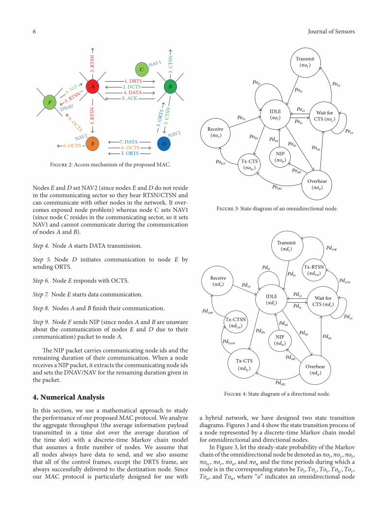
3.6. Channel Access Mechanism. Figure 2 shows the basicoperation, including the channel access mechanism, thescheme to set NAV/DNAV, and the control packet transmis-sion for the proposed MAC protocol. In the figure, nodes 𝐴,
𝐵, and 𝐹 are directional nodes, and nodes 𝐶, 𝐷, and 𝐸 areomnidirectional nodes.
Step 1. Node 𝐴 sends DRTS to node 𝐵.
Step 2. Node 𝐵 responds with DCTS.
Step 3. Nodes 𝐴 and 𝐵 transmit RTSN and CTSN, respec-tively. The RTSN and CTSN are transmitted concurrentlythrough all beams, except the communicating beams (thebeams are pointed towards the sender and receiver node).
6 Journal of Sensors
A B
C
D
F
E
1. DRTS2. DCTS
3. R
TSN
3. RTSN3.
RTS
N
3. C
TSN
3. C
TSN
4. DATA
5. ORTS6. OCTS
6. OCTS
6. OCTS7. DATA
8. ACK
NAV1
NAV2NAV2
DNAV
5. O
RTS
9. NIP
Figure 2: Access mechanism of the proposed MAC.
Nodes 𝐸 and𝐷 set NAV2 (since nodes 𝐸 and𝐷 do not residein the communicating sector so they hear RTSN/CTSN andcan communicate with other nodes in the network. It over-comes exposed node problem) whereas node 𝐶 sets NAV1(since node 𝐶 resides in the communicating sector, so it setsNAV1 and cannot communicate during the communicationof nodes 𝐴 and 𝐵).
Step 4. Node 𝐴 starts DATA transmission.
Step 5. Node 𝐷 initiates communication to node 𝐸 bysending ORTS.
Step 6. Node 𝐸 responds with OCTS.
Step 7. Node 𝐸 starts data communication.
Step 8. Nodes 𝐴 and 𝐵 finish their communication.
Step 9. Node 𝐹 sends NIP (since nodes 𝐴 and 𝐵 are unawareabout the communication of nodes 𝐸 and 𝐷 due to theircommunication) packet to node 𝐴.
The NIP packet carries communicating node ids and theremaining duration of their communication. When a nodereceives a NIP packet, it extracts the communicating node idsand sets the DNAV/NAV for the remaining duration given inthe packet.
4. Numerical Analysis
In this section, we use a mathematical approach to studythe performance of our proposed MAC protocol. We analyzethe aggregate throughput (the average information payloadtransmitted in a time slot over the average duration ofthe time slot) with a discrete-time Markov chain modelthat assumes a finite number of nodes. We assume thatall nodes always have data to send, and we also assumethat all of the control frames, except the DRTS frame, arealways successfully delivered to the destination node. Sinceour MAC protocol is particularly designed for use with
Transmit
Receive
Tx-CTSNIP
Overhear
IDLE Wait forCTS (𝜋oc)(𝜋oi)
(𝜋or)
(𝜋ot )
(𝜋otc)Potcr
Pootc
Poon
Pori
Poitc
PoioPooc
Pocc
Poic
Poci
PoctPoti
Poii
(𝜋oo)
(𝜋on)
Pdni
Figure 3: State diagram of an omnidirectional node.
(𝜋dt)
(𝜋di)
(𝜋dr)
Transmit
Receive
Tx-CTS
Tx-CTSN
NIP
Overhear
IDLE Wait for
Tx-RTSN
Pdrnt
Pdcrn
Pdti
Pdci
Pdic
Pdii
Pdcc
PdocPdio
Pdon
Pdni
Pditc
Pdotc
Pdtccn
Pdcnr
Pdri
(𝜋drn)
(𝜋dtc)
(𝜋dcn)
CTS (𝜋dc)
(𝜋dn)
(𝜋do)
Figure 4: State diagram of a directional node.
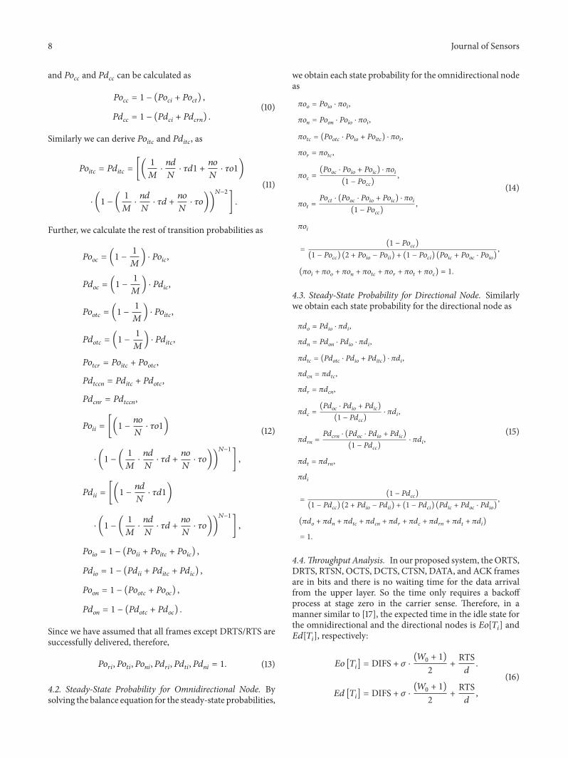
a hybrid network, we have designed two state transitiondiagrams. Figures 3 and 4 show the state transition process ofa node represented by a discrete-time Markov chain modelfor omnidirectional and directional nodes.
In Figure 3, let the steady-state probability of the Markovchain of the omnidirectional node be denoted as𝜋𝑜
𝑖,𝜋𝑜𝑐,𝜋𝑜𝑡,
𝜋𝑜𝑡𝑐, 𝜋𝑜𝑟, 𝜋𝑜𝑜, and 𝜋𝑜
𝑛and the time periods during which a
node is in the corresponding states be 𝑇𝑜𝑖, 𝑇𝑜𝑐, 𝑇𝑜𝑡, 𝑇𝑜𝑡𝑐, 𝑇𝑜𝑟,
𝑇𝑜𝑜, and 𝑇𝑜
𝑛, where “𝑜” indicates an omnidirectional node
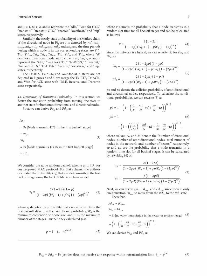
Journal of Sensors 7
and 𝑖, 𝑐, 𝑡, 𝑡𝑐, 𝑟, 𝑜, and 𝑛 represent the “idle,” “wait for CTS,”“transmit,” “transmit-CTS,” “receive,” “overhear,” and “nip”states, respectively.
Similarly, the steady-state probability of theMarkov chainof the directional node in Figure 4 is denoted by 𝜋𝑑
𝑖, 𝜋𝑑𝑐,
𝜋𝑑𝑟𝑛, 𝜋𝑑𝑡, 𝜋𝑑𝑡𝑐, 𝜋𝑑𝑡𝑐𝑛, 𝜋𝑑𝑟, 𝜋𝑑𝑜, and 𝜋𝑑
𝑛and the time periods
during which a node is in the corresponding states are 𝑇𝑑𝑖,
𝑇𝑑𝑐, 𝑇𝑑𝑟𝑛, 𝑇𝑑𝑡, 𝑇𝑑𝑡𝑐, 𝑇𝑑𝑡𝑐𝑛, 𝑇𝑑𝑟, 𝑇𝑑𝑜, and 𝑇𝑑
𝑛, where “𝑑”
denotes a directional node and 𝑖, 𝑐, 𝑟𝑛, 𝑡, 𝑡𝑐, 𝑡𝑐𝑛, 𝑟, 𝑜, and 𝑛represent the “idle,” “wait for CTS,” “tx-RTSN,” “transmit,”“transmit-CTS,” “tx-CTSN,” “receive,” “overhear,” and “nip”states, respectively.
The Tx-RTS, Tx-ACK, and Wait-for-ACK states are notdepicted in Figures 3 and 4; we merge the Tx-RTS, Tx-ACK,and Wait-for-ACK state with IDLE, Receive, and Transmitstate, respectively.
4.1. Derivation of Transition Probability. In this section, wederive the transition probability from moving one state toanother state for both omnidirectional and directional nodes.
First, we can derive 𝑃𝑜𝑖𝑐and 𝑃𝑑
𝑖𝑐as
𝑃𝑜𝑖𝑐
= Pr [Node transmits RTS in the first backoff stage]
= 𝜏𝑜1,
𝑃𝑑𝑖𝑐
= Pr [Node transmits DRTS in the first backoff stage]
= 𝜏𝑑1.
(1)
We consider the same random backoff scheme as in [17] forour proposed MAC protocol. For that scheme, the authorscalculated the probability (𝜏
1) that a node transmits in the first
backoff stage using the backoff Markov chain model:
𝜏1=
2 (1 − 2𝑝) (1 − 𝑝)
(1 − 2𝑝) (𝑊0+ 1) + 𝑝𝑊
0(1 − (2𝑝)
𝑚
)
, (2)
where 𝜏1denotes the probability that a node transmits in the
first backoff stage, 𝑝 is the conditional probability,𝑊0is the
minimum contention window size, and 𝑚 is the maximumnumber of the stages. Further, they calculated 𝑝 as
𝑝 = 1 − (1 − 𝜏)𝑁−2
, (3)
where 𝜏 denotes the probability that a node transmits in arandom slot time for all backoff stages and can be calculatedas follows:
𝜏 =2 (1 − 2𝑝)
(1 − 2𝑝) (𝑊0+ 1) + 𝑝𝑊
0(1 − (2𝑝)
𝑚
)
. (4)
Since the network is a hybrid, we can rewrite (2) for 𝑃𝑜𝑖𝑐and
𝑃𝑑𝑖𝑐as
𝜏𝑜1=
2 (1 − 2𝑝𝑜) (1 − 𝑝𝑜)
(1 − 2𝑝𝑜) (𝑊0+ 1) + 𝑝𝑜𝑊
0(1 − (2𝑝𝑜)
𝑚
)
,
𝜏𝑑1=
2 (1 − 2𝑝𝑑) (1 − 𝑝𝑑)
(1 − 2𝑝𝑑) (𝑊0+ 1) + 𝑝𝑑𝑊
0(1 − (2𝑝𝑑)
𝑚
)
.
(5)
𝑝𝑜 and𝑝𝑑 denote the collision probability of omnidirectionaland directional nodes, respectively. To calculate the condi-tional probabilities, we can rewrite (3) as
𝑝𝑜 = 1 − (1 − (1
𝑀⋅𝑛𝑑
𝑁⋅ 𝜏𝑑 +
𝑛𝑜
𝑁⋅ 𝜏𝑜))
𝑁−2
,
𝑝𝑑 = 1
− (1 − ((1
𝑀)
2
⋅𝑛𝑑
𝑁⋅ 𝜏𝑑 +
1
𝑀⋅𝑛𝑜
𝑁⋅ 𝜏𝑜))
𝑁−2
,
(6)
where 𝑛𝑑, 𝑛𝑜, 𝑁, and 𝑀 denote the “number of directionalnodes, number of omnidirectional nodes, total number ofnodes in the network, and number of beams,” respectively.𝜏𝑜 and 𝜏𝑑 are the probability that a node transmits in arandom time slot for all backoff stages. It can be calculatedby rewriting (4) as
𝜏𝑜 =2 (1 − 2𝑝𝑜)
(1 − 2𝑝𝑜) (𝑊0+ 1) + 𝑝𝑜𝑊
0(1 − (2𝑝𝑜)
𝑚
)
,
𝜏𝑑 =2 (1 − 2𝑝𝑑)
(1 − 2𝑝𝑑) (𝑊0+ 1) + 𝑝𝑑𝑊
0(1 − (2𝑝𝑑)
𝑚
)
.
(7)
Next, we can derive 𝑃𝑜𝑐𝑡, 𝑃𝑑𝑐𝑟𝑛, and 𝑃𝑑
𝑟𝑛𝑡, since there is only
one transition 𝑃𝑑𝑟𝑛𝑡
to move from the 𝜋𝑑𝑟𝑛to the 𝜋𝑑
𝑡state.
Therefore,
𝑃𝑑𝑟𝑛𝑡= 𝑃𝑑𝑐𝑟𝑛,
𝑃𝑜𝑐𝑡= 𝑃𝑑𝑐𝑟𝑛
= Pr [no other transmission in the sector or receiver range]
= (1 − (1
𝑀⋅𝑛𝑑
𝑁⋅ 𝜏𝑑 +
𝑛𝑜
𝑁⋅ 𝜏𝑜))
𝑁−2
.
(8)
We can derive 𝑃𝑜𝑐𝑖and 𝑃𝑑
𝑐𝑖as
𝑃𝑜𝑐𝑖= 𝑃𝑑𝑐𝑖= Pr [sender does not receive any response within retransmission limit 𝑘] = 𝑝𝑘+1 (9)
8 Journal of Sensors
and 𝑃𝑜𝑐𝑐and 𝑃𝑑
𝑐𝑐can be calculated as
𝑃𝑜𝑐𝑐= 1 − (𝑃𝑜
𝑐𝑖+ 𝑃𝑜𝑐𝑡) ,
𝑃𝑑𝑐𝑐= 1 − (𝑃𝑑
𝑐𝑖+ 𝑃𝑑𝑐𝑟𝑛) .
(10)
Similarly we can derive 𝑃𝑜𝑖𝑡𝑐
and 𝑃𝑑𝑖𝑡𝑐, as
𝑃𝑜𝑖𝑡𝑐= 𝑃𝑑𝑖𝑡𝑐= [(
1
𝑀⋅𝑛𝑑
𝑁⋅ 𝜏𝑑1 +
𝑛𝑜
𝑁⋅ 𝜏𝑜1)
⋅ (1 − (1
𝑀⋅𝑛𝑑
𝑁⋅ 𝜏𝑑 +
𝑛𝑜
𝑁⋅ 𝜏𝑜))
𝑁−2
] .
(11)
Further, we calculate the rest of transition probabilities as
𝑃𝑜𝑜𝑐= (1 −
1
𝑀) ⋅ 𝑃𝑜
𝑖𝑐,
𝑃𝑑𝑜𝑐= (1 −
1
𝑀) ⋅ 𝑃𝑑
𝑖𝑐,
𝑃𝑜𝑜𝑡𝑐= (1 −
1
𝑀) ⋅ 𝑃𝑜
𝑖𝑡𝑐,
𝑃𝑑𝑜𝑡𝑐= (1 −
1
𝑀) ⋅ 𝑃𝑑
𝑖𝑡𝑐,
𝑃𝑜𝑡𝑐𝑟= 𝑃𝑜𝑖𝑡𝑐+ 𝑃𝑜𝑜𝑡𝑐,
𝑃𝑑𝑡𝑐𝑐𝑛
= 𝑃𝑑𝑖𝑡𝑐+ 𝑃𝑑𝑜𝑡𝑐,
𝑃𝑑𝑐𝑛𝑟
= 𝑃𝑑𝑡𝑐𝑐𝑛,
𝑃𝑜𝑖𝑖= [(1 −
𝑛𝑜
𝑁⋅ 𝜏𝑜1)
⋅ (1 − (1
𝑀⋅𝑛𝑑
𝑁⋅ 𝜏𝑑 +
𝑛𝑜
𝑁⋅ 𝜏𝑜))
𝑁−1
] ,
𝑃𝑑𝑖𝑖= [(1 −
𝑛𝑑
𝑁⋅ 𝜏𝑑1)
⋅ (1 − (1
𝑀⋅𝑛𝑑
𝑁⋅ 𝜏𝑑 +
𝑛𝑜
𝑁⋅ 𝜏𝑜))
𝑁−1
] ,
𝑃𝑜𝑖𝑜= 1 − (𝑃𝑜
𝑖𝑖+ 𝑃𝑜𝑖𝑡𝑐+ 𝑃𝑜𝑖𝑐) ,
𝑃𝑑𝑖𝑜= 1 − (𝑃𝑑
𝑖𝑖+ 𝑃𝑑𝑖𝑡𝑐+ 𝑃𝑑𝑖𝑐) ,
𝑃𝑜𝑜𝑛= 1 − (𝑃𝑜
𝑜𝑡𝑐+ 𝑃𝑜𝑜𝑐) ,
𝑃𝑑𝑜𝑛= 1 − (𝑃𝑑
𝑜𝑡𝑐+ 𝑃𝑑𝑜𝑐) .
(12)
Since we have assumed that all frames except DRTS/RTS aresuccessfully delivered, therefore,
𝑃𝑜𝑟𝑖, 𝑃𝑜𝑡𝑖, 𝑃𝑜𝑛𝑖, 𝑃𝑑𝑟𝑖, 𝑃𝑑𝑡𝑖, 𝑃𝑑𝑛𝑖= 1. (13)
4.2. Steady-State Probability for Omnidirectional Node. Bysolving the balance equation for the steady-state probabilities,
we obtain each state probability for the omnidirectional nodeas
𝜋𝑜𝑜= 𝑃𝑜𝑖𝑜⋅ 𝜋𝑜𝑖,
𝜋𝑜𝑛= 𝑃𝑜𝑜𝑛⋅ 𝑃𝑜𝑖𝑜⋅ 𝜋𝑜𝑖,
𝜋𝑜𝑡𝑐= (𝑃𝑜
𝑜𝑡𝑐⋅ 𝑃𝑜𝑖𝑜+ 𝑃𝑜𝑖𝑡𝑐) ⋅ 𝜋𝑜𝑖,
𝜋𝑜𝑟= 𝜋𝑜𝑡𝑐,
𝜋𝑜𝑐=(𝑃𝑜𝑜𝑐⋅ 𝑃𝑜𝑖𝑜+ 𝑃𝑜𝑖𝑐) ⋅ 𝜋𝑜𝑖
(1 − 𝑃𝑜𝑐𝑐)
,
𝜋𝑜𝑡=𝑃𝑜𝑐𝑡⋅ (𝑃𝑜𝑜𝑐⋅ 𝑃𝑜𝑖𝑜+ 𝑃𝑜𝑖𝑐) ⋅ 𝜋𝑜𝑖
(1 − 𝑃𝑜𝑐𝑐)
,
𝜋𝑜𝑖
=(1 − 𝑃𝑜
𝑐𝑐)
(1 − 𝑃𝑜𝑐𝑐) (2 + 𝑃𝑜
𝑖𝑜− 𝑃𝑜𝑖𝑖) + (1 − 𝑃𝑜
𝑐𝑖) (𝑃𝑜𝑖𝑐+ 𝑃𝑜𝑜𝑐⋅ 𝑃𝑜𝑖𝑜),
(𝜋𝑜𝑖+ 𝜋𝑜𝑜+ 𝜋𝑜𝑛+ 𝜋𝑜𝑡𝑐+ 𝜋𝑜𝑟+ 𝜋𝑜𝑡+ 𝜋𝑜𝑐) = 1.
(14)
4.3. Steady-State Probability for Directional Node. Similarlywe obtain each state probability for the directional node as
𝜋𝑑𝑜= 𝑃𝑑𝑖𝑜⋅ 𝜋𝑑𝑖,
𝜋𝑑𝑛= 𝑃𝑑𝑜𝑛⋅ 𝑃𝑑𝑖𝑜⋅ 𝜋𝑑𝑖,
𝜋𝑑𝑡𝑐= (𝑃𝑑
𝑜𝑡𝑐⋅ 𝑃𝑑𝑖𝑜+ 𝑃𝑑𝑖𝑡𝑐) ⋅ 𝜋𝑑𝑖,
𝜋𝑑𝑐𝑛= 𝜋𝑑𝑡𝑐,
𝜋𝑑𝑟= 𝜋𝑑𝑐𝑛,
𝜋𝑑𝑐=(𝑃𝑑𝑜𝑐⋅ 𝑃𝑑𝑖𝑜+ 𝑃𝑑𝑖𝑐)
(1 − 𝑃𝑑𝑐𝑐)
⋅ 𝜋𝑑𝑖,
𝜋𝑑𝑟𝑛=𝑃𝑑𝑐𝑟𝑛⋅ (𝑃𝑑𝑜𝑐⋅ 𝑃𝑑𝑖𝑜+ 𝑃𝑑𝑖𝑐)
(1 − 𝑃𝑑𝑐𝑐)
⋅ 𝜋𝑑𝑖,
𝜋𝑑𝑡= 𝜋𝑑𝑟𝑛,
𝜋𝑑𝑖
=(1 − 𝑃𝑑
𝑐𝑐)
(1 − 𝑃𝑑𝑐𝑐) (2 + 𝑃𝑑
𝑖𝑜− 𝑃𝑑𝑖𝑖) + (1 − 𝑃𝑑
𝑐𝑖) (𝑃𝑑𝑖𝑐+ 𝑃𝑑𝑜𝑐⋅ 𝑃𝑑𝑖𝑜),
(𝜋𝑑𝑜+ 𝜋𝑑𝑛+ 𝜋𝑑𝑡𝑐+ 𝜋𝑑𝑐𝑛+ 𝜋𝑑𝑟+ 𝜋𝑑𝑐+ 𝜋𝑑𝑟𝑛+ 𝜋𝑑𝑡
+ 𝜋𝑑𝑖)
= 1.
(15)
4.4.Throughput Analysis. In our proposed system, theORTS,DRTS, RTSN, OCTS, DCTS, CTSN, DATA, and ACK framesare in bits and there is no waiting time for the data arrivalfrom the upper layer. So the time only requires a backoffprocess at stage zero in the carrier sense. Therefore, in amanner similar to [17], the expected time in the idle state forthe omnidirectional and the directional nodes is 𝐸𝑜[𝑇
𝑖] and
𝐸𝑑[𝑇𝑖], respectively:
𝐸𝑜 [𝑇𝑖] = DIFS + 𝜎 ⋅
(𝑊0+ 1)
2+RTS𝑑
.
𝐸𝑑 [𝑇𝑖] = DIFS + 𝜎 ⋅
(𝑊0+ 1)
2+RTS𝑑
,
(16)
Journal of Sensors 9
where 𝜎 is the backoff slot duration and𝑊0is the minimum
backoff window size for stage 0 and 𝑑 is the data rate.As in Figures 3 and 4, there are three transitions to move
from “wait for CTS” state. If the sender receives CTS, itmovesto a “transmit/tx-RTSN” state with “𝑃𝑜
𝑐𝑡/𝑃𝑑𝑐𝑟𝑛” probability;
otherwise, the sender retransmits “ORTS/DRTS” and staysin the same state with “𝑃
𝑐𝑐” probability. It moves into an
“idle” state with “𝑃𝑐𝑖” probability when the sender reaches a
maximum retransmission limit.Therefore, the expectedwaiting time in the “wait for CTS”
state 𝐸𝑜[𝑇𝑐] and 𝐸𝑑[𝑇
𝑐] for the omnidirectional node and
directional node is
𝐸𝑜 [𝑇𝑐] = (𝑃𝑜
𝑐𝑐⋅ 𝐸𝑜𝑐[𝑇𝑐] + 𝑃𝑜
𝑐𝑡⋅ 𝐸𝑜𝑡[𝑇𝑐] + 𝑃𝑜
𝑐𝑖
⋅ 𝐸𝑜𝑖[𝑇𝑐]) ,
𝐸𝑑 [𝑇𝑐] = (𝑃𝑑
𝑐𝑐⋅ 𝐸𝑑𝑐[𝑇𝑐] + 𝑃𝑑
𝑟𝑛𝑡⋅ 𝐸𝑑𝑡[𝑇𝑐] + 𝑃𝑑
𝑐𝑖
⋅ 𝐸𝑑𝑖[𝑇𝑐]) ,
(17)
where 𝐸𝑜𝑐[𝑇𝑐] and 𝐸𝑑
𝑐[𝑇𝑐] are the conditional expectation
of the sender that does not receive CTS within 𝑘 − 1
retransmissions, 𝐸𝑜𝑡[𝑇𝑐] and 𝐸𝑑
𝑡[𝑇𝑐] are for the sender that
receives CTS within the 𝑘 retransmission limit, and 𝐸𝑜𝑖[𝑇𝑐]
and 𝐸𝑜𝑖[𝑇𝑐] denote the sender that reaches the maximum
retransmission limit:
𝐸𝑜𝑐[𝑇𝑐] = [(𝑃𝑜
𝑐𝑐)𝑘−1
⋅ (𝑘 − 1) ⋅ (CTS timeout
+ DIFS + 𝜎 ⋅(𝑊0+ 1)
2+RTS𝑑
)] ,
𝐸𝑑𝑐[𝑇𝑐] = [(𝑃𝑑
𝑐𝑐)𝑘−1
⋅ (𝑘 − 1) ⋅ CTS timeout
+ DIFS + 𝜎.(𝑊0+ 1)
2+RTS𝑑
] ,
𝐸𝑜𝑡[𝑇𝑐] = (𝐸𝑜
𝑐[𝑇𝑐] + (CTS timeout + SIFS)) ,
𝐸𝑑𝑡[𝑇𝑐] = (𝐸𝑑
𝑐[𝑇𝑐] + (CTS timeout + SIFS)) ,
𝐸𝑜𝑖[𝑇𝑐] = (𝑃𝑑
𝑐𝑐)𝑘
𝑘
∑
𝑖=1
(CTS timeout + DIFS + 𝜎
⋅(𝑊0+ 1)
2+RTS𝑑
) ,
𝐸𝑑𝑖[𝑇𝑐] = (𝑃𝑑
𝑐𝑐)𝑘
𝑘
∑
𝑖=1
(CTS timeout + DIFS + 𝜎
⋅(𝑊0+ 1)
2+RTS𝑑
) .
(18)
The expected time spent in other states is given as
𝐸𝑜 [𝑇𝑡] = 𝐸𝑑 [𝑇
𝑡] = (2 ⋅ SIFS + DATA + ACK
𝑑) ,
𝐸𝑑 [𝑇𝑟𝑛] = SIFS + RTSN
𝑑,
𝐸𝑜 [𝑇𝑡𝑐] = 𝐸𝑑 [𝑇
𝑡𝑐] = SIFS + CTS
𝑑,
𝐸𝑜 [𝑇𝑟] = 𝐸𝑑 [𝑇
𝑟] = (2 ⋅ SIFS + DATA + ACK
𝑑) ,
𝐸𝑑 [𝑇𝑐𝑛] = SIFS + CTSN
𝑑,
𝐸𝑜 [𝑇𝑜] = 𝐸𝑑 [𝑇
𝑜] = (DIFS + 5 ⋅ SIFS
+(RTS + CTS + CTSN + RTSN + DATA + ACK)
𝑑) ,
𝐸𝑜 [𝑇𝑛] = 𝐸𝑑 [𝑇
𝑛] = SIFS + NIP
𝑑.
(19)
Finally, we can calculate the network throughput with 𝑁
nodes. Since the network is a hybrid network that consists oftwo types of nodes, the network throughput is
𝑆 = THO + THD, (20)
where
THO =𝑛𝑜/𝑁 ⋅ 𝜋𝑜
𝑟⋅ 𝐸 [𝑃]
{𝜋𝑜𝑖⋅ 𝐸𝑜 [𝑇
𝑖] + 𝜋𝑜
𝑐⋅ 𝐸𝑜 [𝑇
𝑐] + 𝜋𝑜
𝑡⋅ 𝐸𝑜 [𝑇
𝑡] + 𝜋𝑜
𝑡𝑐⋅ 𝐸𝑜 [𝑇
𝑡𝑐] + 𝜋𝑜
𝑟⋅ 𝐸𝑜 [𝑇
𝑟] + 𝜋𝑜
𝑜⋅ 𝐸𝑜 [𝑇
𝑜] + 𝜋𝑜
𝑛⋅ 𝐸𝑜 [𝑇
𝑛]},
THD
={𝑛𝑑/𝑁 ⋅ 𝜋𝑑
𝑟⋅ 𝐸 [𝑃]}
{𝜋𝑑𝑖⋅ 𝐸𝑑 [𝑇
𝑖] + 𝜋𝑑
𝑐⋅ 𝐸𝑑 [𝑇
𝑐] + 𝜋𝑑
𝑟𝑛⋅ 𝐸𝑑 [𝑇
𝑟𝑛] + 𝜋𝑑
𝑡⋅ 𝐸𝑑 [𝑇
𝑡] + 𝜋𝑑
𝑡𝑐⋅ 𝐸𝑑 [𝑇
𝑡𝑐] + 𝜋𝑑
𝑐𝑛⋅ 𝐸𝑑 [𝑇
𝑐𝑛] + 𝜋𝑑
𝑟⋅ 𝐸𝑑 [𝑇
𝑟] + 𝜋𝑑
𝑜⋅ 𝐸𝑑 [𝑇
𝑜] + 𝜋𝑑
𝑛⋅ 𝐸𝑑 [𝑇
𝑛]}
(21)
with 𝐸[𝑃] as the average payload size for the data packet.From (20), we can analyze the aggregate throughput of
the network. In our analysis, we summarize the parameterused to obtain the numerical results for the analytical and thesimulation model in Table 1.
Figures 5(a), 5(b), and 5(c) show a comparison of thetransmission probability of the directional and omnidirec-tional nodes in the network in terms of the number ofnodes, percentage of the directional nodes, and number ofbeams, respectively. As seen in the figure, the transmission
10 Journal of Sensors
Table 1: Parameters used to obtain numerical results.
Packet payload 1024 bytesMAC header 34 bytesPHY header 16 bytesACK 14 bytesORTS/DRTS/RTSN 20 bytesOCTS/DCTS/CTSN/NIP 14 bytesChannel bit rate 54MbpsSlot time 20 𝜇sSIFS 10𝜇sDIFS 50 𝜇s
probability of the directional nodes is much better thanthat of the omnidirectional nodes due to the directionaltransmission in the network. In the case of Figure 5(b) thetransmission probabilities for both types of nodes increase asthe percentage of directional nodes increases in the networkas a result of the directional transmission decreasing theprobability of a collision.
Figures 6(a), 6(b), and 6(c) show the collision probabilityversus the number of nodes, the percentage of directionalnodes in the network, and the number of beams, respectively.As expected, the figures indicate that the collision probabilityincreases as the number of nodes increases (Figure 6(a)).However, when the percentage of directional nodes inthe network increases, the collision probability accordinglydecreases, as seen in Figure 6(b). In the case with the numberof beams shown in Figure 6(c), when the number of beamsincreases, the collision probability decreases, as expected. Inall cases, the collision probability of the directional nodes ismuch lower than that of the omnidirectional nodes.
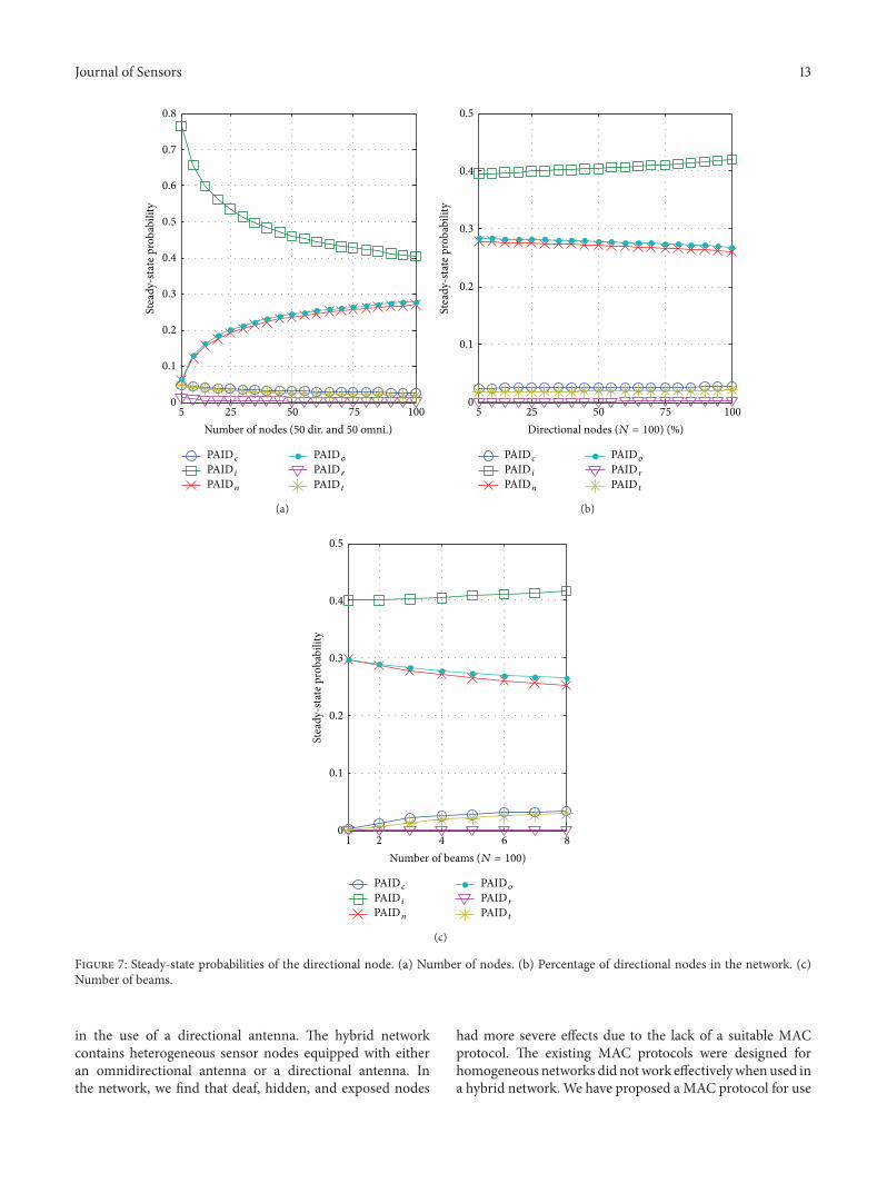
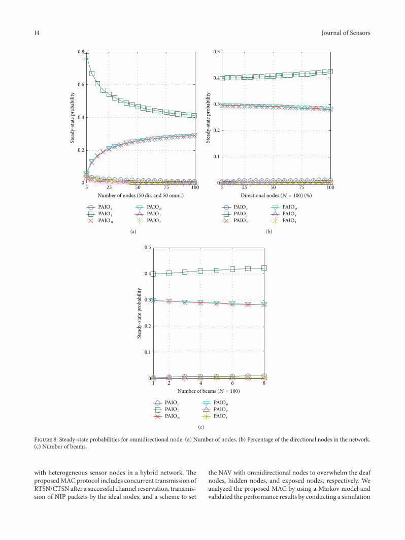
Figures 7 and 8 show steady-state probability of thedirectional and omnidirectional nodes. In the figures, “PAIDand PAIO” denote 𝜋𝑑 and 𝜋𝑜 (directional and omnidirec-tional node states) and “𝑐, 𝑖, 𝑛, 𝑜, 𝑟, and 𝑡” denote thecorresponding states.
In Figures 7 and 8, the PAID𝑖(𝜋𝑑𝑖) and PAIO
𝑖(𝜋𝑜𝑖) states
are the same for all cases because the directional nodes sensethe channel through its beam pointed around the nodes,which acts as an isotropic antenna.Therefore, the probabilityof a node staying in the “idle” state is the same for both kindsof nodes in the network. For the rest of states, we can see thatthe direction nodes have a better probability to stay in theindividual states.
5. Performance Comparison
In this section, we evaluate the performance of theMAC pro-posed for use in the hybrid network. To validate our results,we conducted a simulation using the OPNET simulator. Theparameters of the simulation are given in Table 2.
We have developed a simulation scenario for which allnodes are randomly distributed in a 1500 × 1500m2 area.All of the receiver nodes are located within the sender’s
Table 2: Simulation parameter.
Parameter ValueMaximum number of nodes 100Omnidirectional range 150mDirectional communication range 300mData rate 54MbpsData size 1024 bytes
communication range. The simulation runs for 600 secondsand each result is an average over ten runswith random seeds.We do not consider mobility of the nodes in our simulations.
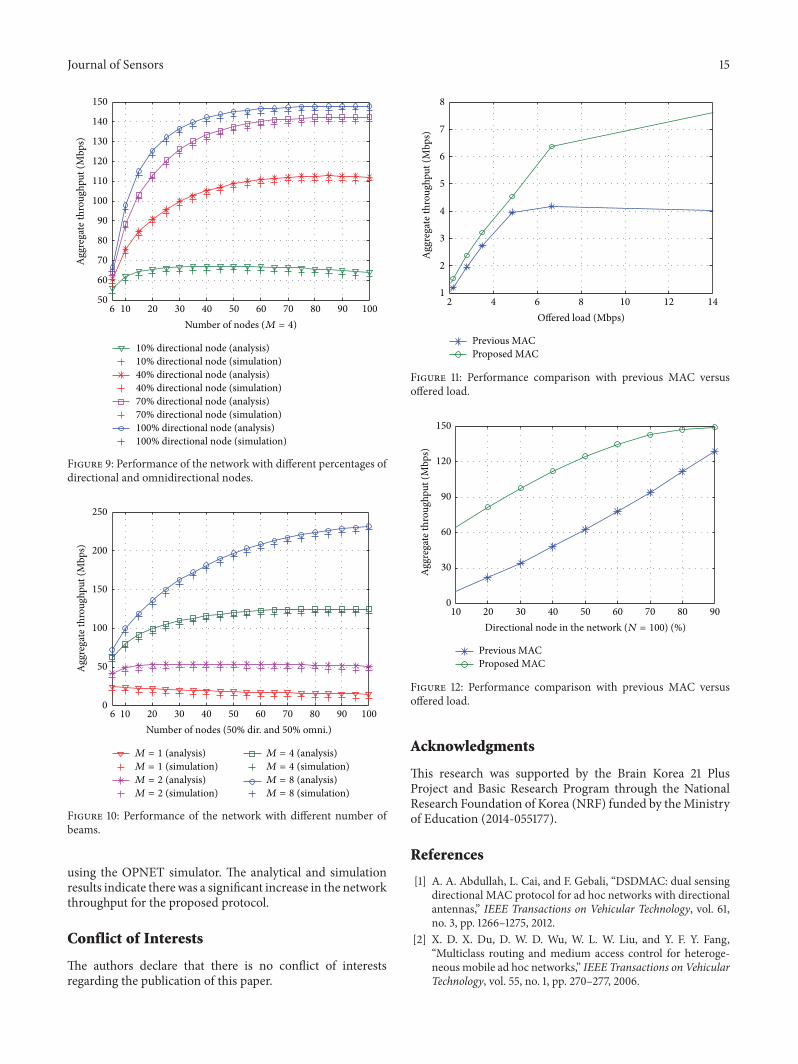
Figures 9 and 10 show the aggregate network throughputof a network versus the variation in the number of nodes inthe network, and the number of nodes is seen to vary from 6to 100 nodes in the network.
In Figure 9, we compared the performance of the networkfor a variation in the percentage of the directional nodeswith four beams in the network. The figure indicates thatwhen the directional nodes comprise 10% of the network,the saturation throughput is less than 70Mbps for 40 nodes.When we increase the percentage of directional nodes to40%, the saturation throughput becomesmore than 110Mbpsat 70 nodes. In the case of 70% of directional nodes, theperformance significantly increases to more than 140Mbpssaturation at a throughput with 90 nodes. The reason forthe improvement in performance in terms of the throughputwith directional nodes is that the directional transmissionincreases the spatial reuse in the network and decreasesthe collision probability. Moreover, the directional antennahas a higher gain than that of an isotropic antenna, so thehigher number of directional nodes provides a significantlyimproved performance with a dense network.
In Figure 10, we compared the performance of the net-work for a varying number of beams of the directionalnodes in the network. In this scenario, half of the nodesare directional nodes and the other half are omnidirectionalnodes. The saturation throughput increases with a densenetwork according to the number of beams because thespatial reuse in the network increases as the number of beamsincreases.
Since our proposedMAC is designed for hybrid network,so we implement DA-MAC [3] for directional nodes andIEEE 802.11 for omnidirectional nodes for simulation. Inthe scenario, there are total hundred nodes in the network.The 50% nodes are directional and the rest of 50% areomnidirectional nodes. We named these implemented MACas previous MAC. To evaluate our results we compared theperformance of our proposed MAC and previous MAC.
Figure 11 shows the aggregate throughput versus offeredload. As the figure, the performance of our proposedMAC is better than that of previous MAC, because thescheme of transmitting NIP and simultaneous transmissionof RTSN/CTSN overcome the deaf and hidden node problemwhile the scheme of setting NAV1 and NAV2 overcomesexposed node problem. On the other hand, in previous
Journal of Sensors 11
0.01
0.02
0.03
0.04
0.05
0.06
Tran
smiss
ion
prob
abili
ty
25 50 75 1005Number of nodes (50 dir. and 50 omni.)
Directional nodeOmnidirectional node
(a)
0.01
0.02
0.03
0.04
0.05
0.06
Tran
smiss
ion
prob
abili
ty
25 50 75 1005Directional nodes (N = 100) (%)
Directional nodeOmnidirectional node
(b)
1 2 4 6 8Number of beams (N = 100)
Directional nodeOmnidirectional node
0.01
0.02
0.03
0.04
0.05
0.06
Tran
smiss
ion
prob
abili
ty
(c)
Figure 5: Transmission probability. (a) Number of nodes. (b) Percentage of directional nodes in the network. (c) Number of beams.
MAC, the nodes follow the DA-MAC (directional node)and IEEE 802.11 (omnidirectional node). In DA-MAC thereis no scheme to overcome the hidden and exposed nodeproblem. Moreover, with IEEE 802.11, there is no scheme toovercome the exposed node problem in hybrid network. So
the hidden and exposed node problem is the main reason ofpoor performance of previous MAC.
Figure 12 shows the aggregate throughput versus percent-age of directional nodes in the network. As the figure, inboth cases the throughput is increasing as the percentage
12 Journal of Sensors
0.1
0.2
0.3
0.4
0.5
0.6
0.7
0.8
Col
lisio
n pr
obab
ility
25 50 75 1005Number of nodes (50 dir. and 50 omni.)
Directional nodeOmnidirectional node
(a)
Directional nodes (N = 100) (%)
0.2
0.3
0.4
0.5
0.6
0.7
0.8
Col
lisio
n pr
obab
ility
25 50 75 1005
Directional nodeOmnidirectional node
(b)
1 2 4 6 80.1
0.2
0.3
0.4
0.5
0.6
0.7
0.8
Col
lisio
n pr
obab
ility
Number of beams (N = 100)
Directional nodeOmnidirectional node
(c)
Figure 6: Collision Probability. (a) Number of nodes. (b) Percentage of directional node in the network. (c) Number of beams.
of directional node is increasing; it shows that we achievebetter spatial reuse in the network with directional antenna.As expected our proposed MAC performs better than that ofthe previous MAC.
6. Conclusion
In this paper, we have considered the intermediate wirelessnetwork (hybrid network) with respect to the advancements
Journal of Sensors 13
0
0.2
0.1
0.4
0.3
0.6
0.5
0.8
0.7St
eady
-sta
te p
roba
bilit
y
25 50 75 1005Number of nodes (50 dir. and 50 omni.)
PAID c
PAID i
PAIDn
PAIDo
PAID r
PAID t
(a)
0
0.2
0.1
0.4
0.3
0.5
25 50 75 1005
PAID c
PAID i
PAIDn
PAIDo
PAID r
PAID t
Stea
dy-s
tate
pro
babi
lity
Directional nodes (N = 100) (%)
(b)
2 4 6 81Number of beams (N = 100)
0
0.1
0.2
0.3
0.4
0.5
Stea
dy-s
tate
pro
babi
lity
PAID c
PAID i
PAIDn
PAIDo
PAID r
PAID t
(c)
Figure 7: Steady-state probabilities of the directional node. (a) Number of nodes. (b) Percentage of directional nodes in the network. (c)Number of beams.
in the use of a directional antenna. The hybrid networkcontains heterogeneous sensor nodes equipped with eitheran omnidirectional antenna or a directional antenna. Inthe network, we find that deaf, hidden, and exposed nodes
had more severe effects due to the lack of a suitable MACprotocol. The existing MAC protocols were designed forhomogeneous networks did notwork effectivelywhenused ina hybrid network. We have proposed a MAC protocol for use
14 Journal of Sensors
0
0.2
0.4
0.6
0.8
Stea
dy-s
tate
pro
babi
lity
25 50 75 1005Number of nodes (50 dir. and 50 omni.)
PAIO c
PAIO i
PAIOn
PAIOo
PAIO r
PAIO t
(a)
0
0.1
0.2
0.3
0.4
0.5
Stea
dy-s
tate
pro
babi
lity
25 50 75 1005Directional nodes (N = 100) (%)
PAIO c
PAIO i
PAIOn
PAIOo
PAIO r
PAIO t
(b)
2 4 6 81Number of beams (N = 100)
0
0.1
0.2
0.3
0.4
0.5
Stea
dy-s
tate
pro
babi
lity
PAIO c
PAIO i
PAIOn
PAIOo
PAIO r
PAIO t
(c)
Figure 8: Steady-state probabilities for omnidirectional node. (a) Number of nodes. (b) Percentage of the directional nodes in the network.(c) Number of beams.
with heterogeneous sensor nodes in a hybrid network. TheproposedMAC protocol includes concurrent transmission ofRTSN/CTSNafter a successful channel reservation, transmis-sion of NIP packets by the ideal nodes, and a scheme to set
the NAV with omnidirectional nodes to overwhelm the deafnodes, hidden nodes, and exposed nodes, respectively. Weanalyzed the proposed MAC by using a Markov model andvalidated the performance results by conducting a simulation
Journal of Sensors 15
650
60
70
80
90
100
110
120
130
140
150
Agg
rega
te th
roug
hput
(Mbp
s)
20 30 40 50 60 70 80 90 10010Number of nodes (M = 4)
10% directional node (analysis)10% directional node (simulation)40% directional node (analysis)40% directional node (simulation) 70% directional node (analysis)70% directional node (simulation)100% directional node (analysis)100% directional node (simulation)
Figure 9: Performance of the network with different percentages ofdirectional and omnidirectional nodes.
10 20 30 40 50 60 70 80 90 1006Number of nodes (50% dir. and 50% omni.)
0
50
100
150
200
250
Agg
rega
te th
roug
hput
(Mbp
s)
M = 1 (analysis)M = 1 (simulation)
M = 2 (simulation)M = 2 (analysis)
M = 4 (analysis)M = 4 (simulation)M = 8 (analysis)M = 8 (simulation)
Figure 10: Performance of the network with different number ofbeams.
using the OPNET simulator. The analytical and simulationresults indicate there was a significant increase in the networkthroughput for the proposed protocol.
Conflict of Interests
The authors declare that there is no conflict of interestsregarding the publication of this paper.
Previous MACProposed MAC
1
2
3
4
5
6
7
8
Agg
rega
te th
roug
hput
(Mbp
s)
4 6 8 10 12 142Offered load (Mbps)
Figure 11: Performance comparison with previous MAC versusoffered load.
0
30
60
90
120
150A
ggre
gate
thro
ughp
ut (M
bps)
20 30 40 50 60 70 80 9010Directional node in the network (N = 100) (%)
Previous MACProposed MAC
Figure 12: Performance comparison with previous MAC versusoffered load.
Acknowledgments
This research was supported by the Brain Korea 21 PlusProject and Basic Research Program through the NationalResearch Foundation of Korea (NRF) funded by theMinistryof Education (2014-055177).
References
[1] A. A. Abdullah, L. Cai, and F. Gebali, “DSDMAC: dual sensingdirectional MAC protocol for ad hoc networks with directionalantennas,” IEEE Transactions on Vehicular Technology, vol. 61,no. 3, pp. 1266–1275, 2012.
[2] X. D. X. Du, D. W. D. Wu, W. L. W. Liu, and Y. F. Y. Fang,“Multiclass routing and medium access control for heteroge-neous mobile ad hoc networks,” IEEE Transactions on VehicularTechnology, vol. 55, no. 1, pp. 270–277, 2006.
16 Journal of Sensors
[3] W. Na, L. Park, and S. Cho, “Deafness-aware MAC protocolfor directional antennas in wireless ad hoc networks,” Ad HocNetworks, vol. 24, pp. 121–134, 2015.
[4] S. Wang, K. Mimis, M. Z. Bocus, G. T. Watkins, and J. P. Coon,“Energy-efficient heterogeneous antenna selection relaying inwireless body area networks,” in Proceedings of the IEEE GlobalCommunications Conference (GLOBECOM ’13), pp. 2472–2477,IEEE, Atlanta, Ga, USA, December 2013.
[5] P. Li, H. Zhai, and Y. Fang, “SDMAC: selectively directionalMAC protocol for wireless mobile ad hoc networks,” WirelessNetworks, vol. 15, no. 6, pp. 805–820, 2009.
[6] R. Ram, “Antenna beamforming and power control for ad hocnetworks,” in Mobile Ad Hoc Networiking, pp. 139–174, Wiey-IEEE Press, New York, NY, USA, 2004.
[7] O. Bazan and M. Jaseemuddin, “A survey on MAC protocolsfor wireless adhoc networks with beamforming antennas,” IEEECommunications Surveys and Tutorials, vol. 14, no. 2, pp. 216–239, 2012.
[8] H.-N. Dai, K.-W. Ng, M. Li, and M.-Y. Wu, “An overview ofusing directional antennas in wireless networks,” InternationalJournal of Communication Systems, vol. 26, no. 4, pp. 413–448,2013.
[9] T. Korakis, G. Jakllari, and L. Tassiulas, “A MAC protocol forfull exploitation of directional antennas in ad-hoc wireless net-works,” in Proceedings of the 4th ACM International Symposiumon Mobile Ad Hoc Networking & Computing (MobiHoc ’03), pp.98–107, Annapolis, Md, USA, June 2003.
[10] G. Jakllari, I. Broustis, T. Korakis, S. V. Krishnamurthy, and L.Tassiulas, “Handling asymmetry in gain in directional antennaequipped ad hoc networks,” in Proceedings of the IEEE 16thInternational Symposium on Personal, Indoor and Mobile RadioCommunications (PIMRC ’05), vol. 2, pp. 1284–1288, IEEE,Berlin, Germany, September 2005.
[11] E. Ulukan and O. Gurbuz, “Angular MAC: a frameworkfor directional antennas in wireless mesh networks,” WirelessNetworks, vol. 14, no. 2, pp. 259–275, 2008.
[12] K. Ghaboosi, “On a novel medium access control protocol forwireless ad hoc networks,” in Proceedings of the 3rd InternationalSymposium on Wireless Communication Systems (ISWCS ’06),pp. 601–604, IEEE, Valencia,Spain, September 2006.
[13] A. I. Alshbatat and L. D. L. Dong, “Adaptive MAC protocolfor UAV communication networks using directional antennas,”in Proceedings of the International Conference on Networking,Sensing and Control (ICNSC ’10), pp. 598–603, IEEE, Chicago,Ill, USA, April 2010.
[14] J. Feng, P. Ren, and S. Yan, “A deafness freeMACprotocol for adhoc networks using directional antennas,” in Proceedings of the4th IEEE Conference on Industrial Electronics and Applications(ICIEA ’09), pp. 449–454, Xi’an, China, May 2009.
[15] M. Takata, M. Bandai, and T.Watanabe, “RI-DMAC: a receiver-initiated directional MAC protocol for deafness problem,”International Journal of Sensor Networks, vol. 5, no. 2, pp. 79–89, 2009.
[16] K. Sundaresan andR. Sivakumar, “Adhoc networkswith hetero-geneous smart antennas: performance analysis and protocols,”Wireless Communications and Mobile Computing, vol. 6, no. 7,pp. 893–916, 2006.
[17] G. Bianchi, “Performance analysis of the IEEE 802.11 distributedcoordination function,” IEEE Journal on Selected Areas inCommunications, vol. 18, no. 3, pp. 535–547, 2000.

International Journal of
AerospaceEngineeringHindawi Publishing Corporationhttp://www.hindawi.com Volume 2014
RoboticsJournal of
Hindawi Publishing Corporationhttp://www.hindawi.com Volume 2014
Hindawi Publishing Corporationhttp://www.hindawi.com Volume 2014
Active and Passive Electronic Components
Control Scienceand Engineering
Journal of
Hindawi Publishing Corporationhttp://www.hindawi.com Volume 2014
International Journal of
RotatingMachinery
Hindawi Publishing Corporationhttp://www.hindawi.com Volume 2014
Hindawi Publishing Corporation http://www.hindawi.com
Journal ofEngineeringVolume 2014
Submit your manuscripts athttp://www.hindawi.com
VLSI Design
Hindawi Publishing Corporationhttp://www.hindawi.com Volume 2014
Hindawi Publishing Corporationhttp://www.hindawi.com Volume 2014
Shock and Vibration
Hindawi Publishing Corporationhttp://www.hindawi.com Volume 2014
Civil EngineeringAdvances in
Acoustics and VibrationAdvances in
Hindawi Publishing Corporationhttp://www.hindawi.com Volume 2014
Hindawi Publishing Corporationhttp://www.hindawi.com Volume 2014
Electrical and Computer Engineering
Journal of
Advances inOptoElectronics
Hindawi Publishing Corporation http://www.hindawi.com
Volume 2014
The Scientific World JournalHindawi Publishing Corporation http://www.hindawi.com Volume 2014
SensorsJournal of
Hindawi Publishing Corporationhttp://www.hindawi.com Volume 2014
Modelling & Simulation in EngineeringHindawi Publishing Corporation http://www.hindawi.com Volume 2014
Hindawi Publishing Corporationhttp://www.hindawi.com Volume 2014
Chemical EngineeringInternational Journal of Antennas and
Propagation
International Journal of
Hindawi Publishing Corporationhttp://www.hindawi.com Volume 2014
Hindawi Publishing Corporationhttp://www.hindawi.com Volume 2014
Navigation and Observation
International Journal of
Hindawi Publishing Corporationhttp://www.hindawi.com Volume 2014
DistributedSensor Networks
International Journal of