research article focusing of spotlight tandem...
TRANSCRIPT
Research ArticleFocusing of Spotlight Tandem-Configuration Bistatic Data withFrequency Scaling Algorithm
Shichao Chen1 Ming Liu23 Jun Wang1 Fugang Lu1 and Mengdao Xing4
1No 203 Research Institute of China Ordnance Industries Xirsquoan 710065 China2Key Laboratory of Modern Teaching Technology Ministry of Education Xirsquoan 710119 China3School of Computer Science Shaanxi Normal University Xirsquoan 710119 China4Key Lab for Radar Signal Processing Xidian University Xirsquoan 710071 China
Correspondence should be addressed to Ming Liu mliusnnueducn
Received 30 April 2016 Accepted 1 September 2016
Academic Editor Ding-Bing Lin
Copyright copy 2016 Shichao Chen et al This is an open access article distributed under the Creative Commons Attribution Licensewhich permits unrestricted use distribution and reproduction in any medium provided the original work is properly cited
A frequency scaling (FS) imaging algorithm is proposed for spotlight bistatic SAR data processing Range cell migration correction(RCMC) is realized through phasemultiplicationThe proposed algorithm is insensitive to the length of the baseline due to the highprecision of the point target (PT) spectrum that we are based on It is capable of handling bistatic SAR data with a large baseline torange ratioThe algorithms suitable for small and high squint angles are both discussed according to whether the range dependenceof the second range compression (SRC) can be neglected or not Simulated experiments validate the effectiveness of the proposedalgorithm
1 Introduction
Bistatic synthetic aperture radar (SAR) imaging has beenwidely discussed in recent years [1ndash4] Besides the syn-chronization problems [5 6] fast imaging algorithms arestill in search However we cannot acquire accurate bistaticpoint target (PT) spectrum through the principle of station-ary phase (POSP) because of the double-square-root termexisting in the range history of bistatic SAR Although thetime domain method is the best in theory it accomplishesoptimum reconstruction with heavier computational burdenthan the frequency domain imaging algorithms [7ndash9] Thenumerical methods [10ndash12] can handle the bistatic SARfocusing well however they also suffer the computationalburden [13ndash15] The accurate analytical PT spectrum is theprecondition of designing most fast bistatic imaging algo-rithms in the frequency domain and some effective spectrain the frequency domain have been presented recently [13ndash17] and many imaging algorithms have been proposed basedon them Tandem bistatic SAR has a simple formation andis relatively easy to accomplish in engineering which has
a bright future in multiple applications [18 19] Wu et al[20 21] deduced an exact analytical PT spectrum of bistaticSAR in stripmapmode based on the concept of instantaneousDoppler wavenumber (IDW) [22] in tandem configuration
We focus on the well-known tandem configuration hereA frequency scaling (FS) imaging algorithm is proposedin this paper for bistatic SAR imaging in spotlight modebased on the spectrum presented in [20] The process isimplemented in the frequency domain and no interpolationis neededThe azimuth spectral folding effect is solved by thecombination of the subaperture approach and the derampingprocess when the azimuth bandwidth is larger than the pulserepetition frequency (PRF) Due to the high precision ofthe spectrum the proposed algorithm is capable of handlingbistatic SAR data with a large baseline
The paper is organized as follows In Section 2 thegeometry and the signal model of spotlight bistatic SAR areintroduced The proposed FS algorithm is discussed in detailin Section 3 for both small and high squint angles And theperformance of the proposed algorithm is given in Section 4with simulations Conclusions are drawn in Section 5
Hindawi Publishing CorporationInternational Journal of Antennas and PropagationVolume 2016 Article ID 3251082 15 pageshttpdxdoiorg10115520163251082
2 International Journal of Antennas and Propagation
2hTx Rx
120579T 120579R
RT RR
2120573
RB
P
Figure 1 Spotlight bistatic SAR geometry in tandem configuration
2 Geometry Relationship and Signal Model ofSpotlight Bistatic SAR
Figure 1 shows the geometry of spotlight bistatic SAR theantenna is constantly steering to the imaging spot during thewhole synthetic aperture time to realize a finer azimuth reso-lution 119879119909 and 119877119909 represent the transmitter and the receiverrespectively They travel along the same track with the samevelocity V and 119877119879 and 119877119877 are the slant distances from thetarget 119875 to the transmitter and the receiver respectively 120579119879and 120579119877 are the corresponding squint angles 119877119861 is the closestdistance from the target to the flight track120573 is the half bistaticangle and ℎ is half the length of the baseline
In spotlightmode suppose that radar transmits the linearfrequency-modulated (LFM) pulses and the echo signal afterdechirp on receiver can be written as
119904 (120591 119883) = 120590119901119882119886 (119883) sdot rect[120591 minus [119877119879 (119905) + 119877119877 (119905)] 119888119879119901 ]sdot exp 119895 [minus2120587119888 120574 (120591 minus 119877ref119888 ) 119877Δ minus 2120587119888 119891119888119877Δ+ 1205871205741198882 1198772Δ]
(1)
where 120590119901 stands for the bistatic backscattering coefficient
rect (119909) = 1 |119909| le 120 |119909| gt 12
(2)
represents the rectangular window119882119886(sdot) is the shape of theantenna illumination 119883 = V119905 is the displacement of theplatform in azimuth and 120591 and 119905 are the fast and dwell timerespectively119879119901 is the pulse duration 120574 is the chirp rate119877ref =2119877119904 is the reference range for dechirp119877119904 is the closest distancefrom the scene center to the flight track 119888 is the speed of light119891119888 is the carrier frequency and 119877Δ = 119877119879 + 119877119877 minus 119877ref
Transforming the signal into the range wavenumberdomain in case of large time bandwidth product [23] thesignal can be expressed as
119904 (Δ119896119877 119883) = 120590119901119882119886 (119883) rect [ Δ119896119877119887119888119879119875] exp (minus119895119896119877119877Δ)
otimes exp(minus119895Δ11989621198772119887 ) (3)
where 119896119877 = 119896119877119888 + Δ119896119877 is the range wavenumber 119896119877119888 =2120587119891119888119888 is the center of 119896119877 Δ119896119877 is the variation of the rangewavenumber 119887 = 21205871205741198882 and ldquootimesrdquo means the convolutionoperation
3 Bistatic FS Algorithm
31 FS Imaging Algorithm for Tandem Bistatic SAR withSmall Squint Angles Transforming the signal into the two-dimensional (2D) wavenumber domain based on the IDWconcept [22] we have
119904 (Δ119896119877 119896119883) = 120590119901119882119886 (119896119883) rect[ Δ119896119877119887119888119879119901]sdot exp [minus119895 (119877119861 + ℎ tan120573) sdot radic41198962119877cos2120573 minus 1198962119883]sdot exp (minus119895119909119901119896119883) sdot exp (119895Δ119896119877119877ref) otimes exp(minus119895Δ11989621198772119887 )
(4)
where 119896119883 represents the Doppler wavenumber and 119909119901 indi-cates the azimuth position where the imaged target is located
The proposed FS imaging algorithm is based on thisequation Wu et al deduced an exact analytical expression ofthe half bistatic angle120573(119896119877 119896119883 119877119861 ℎ) for tandembistatic SAR[21] After substituting it into (4) and making Taylor seriesexpansion up to the cubic termwith respect toΔ119896119877 the signalcomes to
119904 (Δ119896119877 119896119883) = 120590119901119882119886 (119896119883) rect[ Δ119896119877119887119888119879119901 ] exp (1198951206010)sdot exp (minus119895119896119883119909119901)sdot exp (minus1198951206011Δ119896119877) exp (1198951206012Δ1198962119877 + 1198951206013Δ1198963119877)
otimes exp(minus119895Δ11989621198772119887 )
(5)
The detailed expressions of 120573(119896119877 119896119883 119877119861 ℎ) 1206010 1206011 1206012and 1206013 are given in Appendix The expressions may seemrather complicated due to the complex formation of thespectrum However they will turn to be the familiar azimuthmodulation term 1206010 = minus119877119861radic41198962119877119888 minus 1198962119883 the range cell migra-
tion (RCM) factor 1206011 = 2119877119861radic1 minus 1198962119883(41198962119877119888) minus 119877ref and the
International Journal of Antennas and Propagation 3
second range compression term src = exp[119895(21198771198611198962119883(radic41198962119877119888 minus 1198962119883)3)Δ1198962119877 + 119895(81198771198611198962119883119896119877119888(radic41198962119877119888 minus 1198962119883)5)Δ1198963119877] inmonostatic case when ℎ = 0 120573 = 0
In the following we fit a straight line to the RCM factor
1206011 = 119860 + 119861 sdot Δ119903 (6)
where 119860 = 1206011|119877119861=119877119904 119861 = 1205971206011120597119877119861|119877119861=119877119904 and Δ119903 = 2119877119861minus119877ref To see the physical implications of the parametersclearly again we can get 119860 = 2119877119904radic1 minus 119896211988341198962119877119888 minus 119877ref and119861minus1 = radic1 minus 119896211988341198962119877119888 which is just the familiar scale factor inmonostatic case when ℎ = 0 120573 = 0 The profile error causedby (6) is much smaller than the range resolution and can beneglected
Substituting (6) into (5) the signal arrives at
119904 (Δ119896119877 119896119883) = 120590119901119882119886 (119896119883) rect[ Δ119896119877(119887119888119879119901)] exp (1198951206010)sdot exp (minus119895119896119883119909119901) sdot exp [minus119895 (119860 + 119861Δ119903) Δ119896119877]sdot exp (1198951206012Δ1198962119877 + 1198951206013Δ1198963119877) otimes exp(minus119895Δ119896
21198772119887 )
(7)
To equalize the RCM of all the ranges to the one ofthe scene center resembling the monostatic case [23] thefrequency scaling function is given as
119867FS (Δ119896119877 119896119883) = exp[119895Δ11989621198772119887 (1 minus 1198610119861 )] (8)
where 1198610 = 119861(119896119883119888) and 119896119883119888 = 119896119877119888(sin 1205791198790 + sin 1205791198770) is thecenter of 119896119883 1205791198790 and 1205791198770 are the squint angles from the scenecenter to the transmitter and the receiver at zero time Thereason for introducing 1198610 into the scale factor is to reducethe amount of shift in range caused by the scaling operationwhen the squint angles are high ensuring that the signal afterscaling is still in the bandwidth that we are dealing withWhen the system works with small squint angles 1198610 = 1 canbe chosen accordingly Details about this issue are discussedin [24] in monostatic case
The multiplication between (7) and (8) results in
119904 (Δ119896119877 119896119883) = 120590119901119882119886 (119896119883) rect[1198610Δ119896119877119861119887119888119879119901 ] exp (1198951206010)sdot exp [minus119895 (119860119861 + Δ119903)1198610Δ119896119877] exp (minus119895119896119883119909119901)sdot exp[1198951198610 (119861 minus 1198610)21198871198612 Δ1198962119877]sdot exp(119895120601211986120Δ11989621198771198612 + 119895120601311986130Δ11989631198771198613 )
otimes exp(minus1198951198610Δ11989621198772119887119861 )
(9)
From the comparison between (7) and (9) it can be seenthat the space-variant term 119861Δ119903 in the RCM term has beeneliminated The linear phase term Δ1198961198771198610Δ119903 that indicatesthe range position of the target and the bulk range shiftterm Δ1198961198771198610119860119861 have emerged After an inverse fast Fouriertransform (IFFT) in range119867RVPC is multiplied by the signalto correct the range time shift caused by the term called theresidual video phase (RVP) which results from the dechirpoperation on receiver
119867RVPC (119910119904 119896119883) = exp(minus119895 119887119861211986101199102119904) (10)
where 119910119904 indicates the range summation of the transmitterand the receiver of bistatic SAR and 119910119904 and Δ119896119877 are Fouriertransform pairs
Again transforming the signal into the 2D wavenumberdomain the signal moves to
119904 (Δ119896119877 119896119883) = 120590119901119882119886 (119896119883) rect[1198610Δ119896119877119861119887119888119879119901 ] exp (1198951206010)sdot exp (minus119895119896119883119909119901)sdot exp [minus119895 (119860119861 + Δ119903)1198610Δ119896119877]sdot exp[1198951198610 (119861 minus 1198610)21198871198612 Δ1198962119877]sdot exp(119895120601211986120Δ11989621198771198612 + 119895120601311986130Δ11989631198771198613 )
(11)
Then the inverse frequency scaling function is intro-duced to correct the second-order range phase error causedby the frequency scaling operation
119867IFS (Δ119896119877 119896119883) = exp[minus119895(119861 minus 1198610)21198871198612 1198610Δ1198962119877] (12)
The following operation is the bulk range shift functionfor the RCMC
119867RMC (Δ119896119877 119896119883) = exp(119895Δ119896119877119860 sdot 1198610119861 ) (13)
The range dependence of SRC can be neglected when thebistatic SAR systemworks with small squint angles and it canbe compensated with the parameters of the scene center TheSRC function is given as
119867SRC0 (Δ119896119877 119896119883)= exp(minus1198951206012011986120Δ11989621198771198612 minus 1198951206013011986130Δ11989631198771198613 ) (14)
where 12060120 = 1206012|119877119861=119877119904 and 12060130 = 1206013|119877119861=119877119904 The residual phaseerror caused by the approximation will be smaller than 1205874which will not give a crucial influence to the final imagingquality However when the squint angles are high enough
4 International Journal of Antennas and Propagation
neglecting the influence of the approximation will no longerbe available In this situation we can extend the nonlinearchirp scaling algorithm (NCSA) [24] of the monostatic caseinto the bistatic one
The operations in range are finished after transformingthe signal into the (119910119904 119896119883) domain
If the azimuth bandwidth is smaller than PRF theazimuth compression filter can be directly given as
119867azi (119910119904 119896119883) = exp [119895 (119861 + ℎ tan ) sdot 1] (15)
Note that due to the change of the image in range as isshown in (11) we have to accommodate the range parameter119877119861 into 119861 = 119877119904 + (119877119861 minus 119877119904)1198610 so are the range-dependentvariables and 1 At the end of the whole imaging processan IFFT is performed in azimuth to transform the focuseddata into the complex image domain
However the PRF is usually smaller than the wholeazimuth bandwidth in practice in spotlight mode especiallyin spaceborne case thus the imaging algorithms cannotbe directly applied into the whole aperture because of thespectral folding effect One way to solve the problem is thesubaperture method and combining it with the derampingprocessThe data is divided into several subapertures accord-ing to the azimuth time ensuring that the bandwidth withineach subaperture is smaller than PRF The FS algorithm isthen implemented in each subaperture
In the following we come to get the high-order phasecompensation function to transform the bistatic azimuthphase history into a purely quadratic one as the monostaticcase [23] Making Taylor series expansion of the phase termin (15) with respect to 119896119883
120601AZ (119910119904 119896119883) = 120601AZ (119910119904 119896119883119888)+ 1206011015840AZ (119910119904 119896119883119888) (119896119883 minus 119896119883119888)+ 12060110158401015840AZ (119910119904 119896119883119888) (119896119883 minus 119896119883119888)22+ 119867AS (119910119904 119896119883)
(16)
119867AS(119910119904 119896119883) contains the high-order terms of 120601AZ Afterthe compensation of 119867AS(119910119904 119896119883) the purely quadratic termemerges On analog of the monostatic case [23] the deramp-ing function is given after an IFFT with respect to 119896119883119867DERAMP (119910119904 119883) = exp[minus119895 V21199052212060110158401015840AZ (119910119904 119896119883119888)]
119905start + 1199050 (119894) le 119905 le 119905end + 1199050 (119894) (17)
where 119905start and 119905end are the start and the end time ofthe 119894th subaperture and 1199050(119894) is the central time of the 119894thsubaperture In the end the interested image is obtained witha full aperture FFT in azimuth after the subapertures arerecombined
To summarize andmake the proposed FS algorithmmoreclearly the workflows of the proposed FS algorithm are given
as follows (1) divide the bistatic SAR data into subapertures(2) perform azimuth FFT and implement the frequencyscaling by (8) (3) perform range IFFT and implementresidual video phase correction by (10) (4) perform rangeFFT and implement the inverse frequency scaling by (12)the bulk range shift for RCMC by (13) and the second rangecompression by (14) (5) perform range IFFT and implementhigh-order terms compensation with respect to the Dopplerwavenumber (6) perform azimuth IFFT and implementderamping by (17) and (7) recombine the subapertures andperform full aperture azimuth FFT to obtain the final bistaticSAR image The block diagram of the proposed FS imagingalgorithm is shown in Figure 2
32 FS Imaging Algorithm for Tandem Bistatic SAR with HighSquint Angles In some cases the bistatic SAR system workswith high squint angles such as observing the interestedobject which is squint-depended or inspecting the frontsituationsThe range dependence of SRC has to be taken intoaccount in such cases Taking (14) to compensate the SRCwould be inappropriate the residual phase error will be largerthan 1205874 and ideal focusing quality cannot be guaranteedFacing the problem one instinctive way is to extend theNCSA in monostatic case into the bistatic one Although theproblem can also be solved by processing small range blocksit requires a large overlap of blocks which will make theprocess inefficient [24]
To eliminate the range dependence of SRC firstly a third-order filter term is introduced
119867TF (Δ119896119877 119896119883)= exp[minus11989512060130 (1198610119861 )
3 Δ1198963119877] exp (119895119889119898Δ1198963119877) (18)
The coefficient 119889119898 will be given subsequently Similar tothe monostatic case we believe in the approximation thatthe third-order term of SRC can be compensated by theparameters of the scene center In the same time a new third-order phase term is introduced and thus the second-orderterm in the SRC is preserved for the scaling operation TheSRC term shown by (14) is replaced by (18) accordingly Andthe signal arrives at
119904 (Δ119896119877 119896119883) = 120590119901119882119886 (119896119883) rect[1198610Δ119896119877119861119887119888119879119901 ] exp (1198951206010)sdot exp (minus119895119896119883119909119901) sdot exp (minus1198951198610Δ119896119877Δ119903)sdot exp(minus119895Δ11989621198772119887119898 ) exp (119895119889119898Δ1198963119877)
(19)
where 119887119898 = minus11986122119861201206012 Using the POSP and neglecting theinfluence of the third-order phase to the stationary point thesignal is subsequently transformed into the (119910119904 119896119883) domain
119904 (119910119904 119896119883) = 120590119901119882119886 (119896119883) rect[1198610119887119898 (119910119904 minus 1198610Δ119903)119861119887119888119879119901 ]
International Journal of Antennas and Propagation 5
Azimuth FFT
Range IFFT
Range FFT
Range IFFT
Azimuth IFFT
Bistatic SARraw data
Bistatic SARimage
Subaperture formation
Subaperture recombination
Full aperture azimuth FFT
HFS
HRVPC
HIFS
HRMC
HSRC0
HCOMP
HDERAMP
Figure 2 Block diagram of tandem bistatic SAR in spotlight mode with small squint angles
sdot exp (1198951206010) exp (minus119895119896119883119909119901)sdot exp [1198951198871198982 (119910119904 minus 1198610Δ119903)2]sdot exp [1198951198891198981198873119898 (119910119904 minus 1198610Δ119903)3]
(20)
Multiply the signal by the nonlinear scaling functionwhich is constructed as
119867SCALE (119910119904 119896119883) = exp(11989511990222 1199102119904 ) exp (11989511990231199103119904 ) (21)
A range FFT is performed to the signal after the multi-plication between (20) and (21) We take a close look at thephase termΦ
Φ = minusΔ119896119877 + 1198871198981198610Δ119903119887119898 + 1199022 Δ119896119877+ 12 (119887119898 + 1199022)2 [119887119898 (Δ119896119877 minus 11990221198610Δ119903)
2
+ 1199022 (Δ119896119877 + 1198871198981198610Δ119903)2]+ 1(119887119898 + 1199022)3 [119889119898119887
3119898 (Δ119896119877 minus 11990221198610Δ119903)3
+ 1199023 (Δ119896119877 + 1198871198981198610Δ119903)3]
(22)
Due to the range dependence of 119887119898 we fit it by a straightline
119887119898 = 1198871198980 + 119887119904Δ119903 (23)
where 1198871198980 = 119887119898|119877119861=119877119904 and 119887119904 = (120597119887119898120597119877119861)|119877119861=119877119904 provided thatthe following approximations are met
1119887119898 + 1199022 asymp11198871198980 + 1199022 minus
1198871199041198610Δ119903(1198871198980 + 1199022)2 1
(119887119898 + 1199022)2 asymp1
(1198871198980 + 1199022)2 minus21198871199041198610Δ119903(1198871198980 + 1199022) (1198871198980 + 1199022)2
1(119887119898 + 1199022)3 asymp
1(1198871198980 + 1199022)3
(24)
Substituting (23) and (24) into (22) the phase term comesto
Φ = 1198621 (119889119898 1199022 1199023 119896119909 Δ119896119877)+ 1198622 (119889119898 1199022 1199023 119896119909) Δ119903Δ119896119877+ 1198623 (119889119898 1199022 1199023 119896119909) Δ1199032Δ119896119877+ 1198624 (119889119898 1199022 1199023 119896119909) Δ119903Δ1198962119877+ 1198625 (119889119898 1199022 1199023 119896119909 Δ119903)
(25)
where
1198621 = minus 12 (1198871198980 + 1199022)Δ1198962119877 +11988911989811988731198980 + 1199023(1198871198980 + 1199022)3Δ119896
3119877
1198622 = minus 11988711989801198871198980 + 1199022 1198623 = minus 1198871199041199022(1198871198980 + 1199022)2 +
3119902311988721198980 + 31198891198981198873119898011990222(1198871198980 + 1199022)3
6 International Journal of Antennas and Propagation
1198624 = 1198871199042 (1198871198980 + 1199022)2 +311990231198871198980 minus 3119889119898119902211988731198980(1198871198980 + 1199022)3
1198625 = 119887119898011990222 (1198871198980 + 1199022)11986120Δ2119903+ [119902311988731198980 minus 1198891198981198873119898011990232(1198871198980 + 1199022)3 + 119887119904119902222 (1198871198980 + 1199022)2]119861
30Δ3119903
(26)
Making 1198622 = minus1120583 and 1198623 = 1198624 = 0 to eliminate theterms that are space-variant we get 1199022 = 1198871198980(120583 minus 1) 1199023 =119887119904(120583minus1)6 and119889119898 = (120583minus05)1198871199043(120583minus1)11988731198980The scaling factor120583 = 119861119861(119870119883ref ) and119870119883ref is chosen to bemin(119896119883)(1+119861119891119888)here and the value can be adjusted for satisfying imagingresults [24] Substituting the results into (25) the signalarrives at
119904 (Δ119896119877 119896119883) = 120590119901119882119886 (119896119883) rect[ 1198610Δ1198961198771198871198881198791199011198612120583] exp (1198951206010)sdot exp (minus119895119896119883119909119901) sdot exp119895 [minus1198610Δ119903120583 Δ119896119877minus 121205831198871198980Δ1198962119877 +
1198871199046120583 (120583 minus 1) 11988731198980Δ1198963119877]
sdot exp119895 [11988711989802 (1 minus 1120583)11986120Δ1199032
+ 1198871199046 (1 minus 1120583)11986130Δ1199033]
(27)
As can be seen the range dependence of SRC has beeneliminated The function for range compression is given as
119867SRC2 (Δ119896119877 119896119883)= exp[ 121205831198871198980Δ1198962119877 minus
1198871199046120583 (120583 minus 1) 11988731198980Δ1198963119877] (28)
And then the phase correction factor is given as
119867PCF (119910119904 119896119883) = minus11988711989802 (1 minus 1120583)11986120Δ1199032
minus 1198871199046 (1 minus 1120583)11986130Δ1199033(29)
To construct accurate azimuth compression filter we haveto accommodate 119877119861 into 119861 = 119877119904 + (119877119861 minus 119877119904)1205831198610 accordingto (27) so are the range-dependent parameters and 1
119867AZ (119910119904 119896119883) = exp [119895 (119861 + ℎ tan ) sdot 1] (30)
An azimuth IFFT is performed to transform the focuseddata into the complex image domain in the end
Similarly we summarize the proposed nonlinear FS algo-rithm that is suitable for high squint angle bistatic SAR The
corresponding workflows are given as follows (1) performazimuth FFT and implement frequency scaling by (8) (2)perform range IFFT and implement residual video phasecorrection by (10) (3) perform range FFT and implementthe inverse frequency scaling by (12) the bulk range shift forRCMC by (13) and the third-order filter by (18) (4) performrange IFFT and implement nonlinear frequency scaling by(21) (5) perform range FFT and implement the second-orderrange compression by (28) (6) perform range IFFT andimplement phase correction by (29) and azimuth compres-sion by (30) and (7) perform azimuth IFFT to obtain the finalbistatic SAR image The block diagram is shown in Figure 3
From the above discussion we can tell that the rangehistory of bistatic SAR is the sum of two square roots whichresults in different bistatic spectrum from the monostaticcase The different bistatic spectrum leads to different rangecell migration Thus the conventional FS algorithm cannotbe directly utilized into the bistatic case In this paper wedesign a new frequency scaling algorithm which is suitablefor bistatic case The proposed bistatic frequency scalingfunction is established based on an exact analytical bistaticspectrum to realize range-dependent RCM correction Andthe corresponding functions for bistatic FS algorithm are alsoestablished such as the inverse frequency scaling functionthe residual video phase correction function the rangemigration correction function and the second range com-pression function We construct all these new functionsbased on the bistatic spectrum Besides the range-dependentparameters need to be updated for bistatic case In additiona nonlinear frequency scaling algorithm is proposed todeal with the high squint angle bistatic SAR based on theanalytical bistatic spectrum We also establish the functionsof the nonlinear FS algorithm for bistatic SAR accordinglyAlthough these functions for the bistatic FS algorithm aremuchmore complex than themonostatic one fortunately wecan evaluate the correctness of the algorithm by degeneratingthe conditions into the monostatic case In practice we canchoose the suitable algorithm according to the squint angles
4 Simulation Results
41 Simulations with Small Squint Angles Experiments arecarried out to validate the effectiveness of the proposed algo-rithm Table 1 illustrates the main parameters of the exper-iment in three cases in tandem configuration We put ninepoint targets in the imaging scene with the center one locatedat (0 0) The distance between any two neighboring targetsis 1500m in both range and azimuth Taking Case I forillustration the profile error caused by the linear approxi-mation of the RCM (6) is shown in Figure 4 which is far lessthan the range resolutionThe influence can be neglectedTheresidual phase error of SRC for the edge target compensatedby the local 119867SRC0 (14) is shown in Figure 5 As can be seenthe error is tolerable The final imaging results of the centerand the edge target by using the proposed FS algorithm areshown in Figure 6We can see that they are quite well focusedthe detailed values of the impulse-response width (IRW) thepeak sidelobe ratio (PSLR) and the integrated sidelobe ratio(ISLR) are shown in Table 2with theoretic values (IRW PSLR
International Journal of Antennas and Propagation 7
Azimuth FFT
Range IFFT
Range FFT
Range FFT
Range IFFT
Range IFFT
Azimuth IFFT
Bistatic SARraw data
Bistatic SARimage
HFS
HRVPC
HIFS
HRMC
HTF
HSRC2
HSCALE
HPCF
HAZ
Figure 3 Block diagram of tandem bistatic SAR with high squint angles
Table 1 Simulation parameters
Case I Case II Case III
Range bandwidth 200MHz
PRF 3000Hz
Carrier frequency 10GHz
Platform velocity 7000msClosest distance from theflight track to the scene center
600 km
Illumination time 134 s 144 s 161 s
Range to reference target 6119 km 6357 km 6708 km
Length of the baseline 240 km 420 km 600 km
Squint angle 1131∘(T) minus1131∘(R) 1929∘(T) minus1929∘(R) 2657∘(T) minus2657∘(R)
and ISLR) 075m in range 1m in azimuth minus133 dB andminus10 dB respectivelyTo show the advantage of the proposed algorithm we
compare it with theMSR andDMOspectra based algorithmsSatisfying focusing quality can be obtained by using all thealgorithms for Case I except the DMO based one For CaseII the baseline increases to 420 km and the imaging resultsobtained by using different algorithms are shown in Figures7ndash9 respectively As can be seen the center target is stillwell focused by using both the proposed and the MSR basedalgorithms while the imaging result obtained by using theDMO spectrum based algorithm is much worse than theothers As for the edge target the focusing qualities differmuch under different algorithms As can be seen the oneobtained by using the proposed algorithm is the best
In the following we come to Case III with the baseline600 km corresponding imaging results by using the algo-rithms are shown in Figures 10ndash12 respectively Again idealfocusing results can be obtained for the center target withboth the proposed and the MSR spectrum based algorithmsbut not the DMO spectrum based one The focusing qualitydegrades dramatically with the increasing length of the base-line As for the edge target the focusing qualities are intoler-able by using all the algorithms except the proposed one Ascan be seen the focusing quality for the edge target decreasesby using the DMO and the MSR based algorithms in thiscase The reason for the phenomenon lies in the fact thatwith the increasing length of the baseline the precision of theDMO and MSR spectrum degrades and the correspondingimaging results based on them degrade accordingly The
8 International Journal of Antennas and Propagation
Table 2 Quality parameters of impulse-response function for Case I
Range AzimuthResolution (m) PSLR (dB) ISLR (dB) Resolution (m) PSLR (dB) ISLR (dB)
Reference 075 minus132626 minus97577 10625 minus132669 minus97605Edge 075 minus132618 minus97502 10625 minus132639 minus97520
0 200 400 6000
001
002
003
Azimuth samples
Mag
nitu
de (m
)
Edge targetCenter target
Figure 4 Profile error caused by (13)
detailed values of the IRWPSLR and ISLRof the center targetunder different algorithms for Case II and Case III are shownin Table 3 and the corresponding descriptions of the edgetarget are given in Table 4
We can tell that the proposed algorithm is capable ofdealing with spotlight bistatic SAR data with a large baselineNote that for the MSR spectrum based algorithm we onlyexpand the Taylor series expansion up to the third term forcomparison here For better focusing quality of the MSRbased algorithm higher orders can be expanded
42 Simulations with High Squint Angles In the followingwe take a look at the case with high squint angels The mainparameters are shown in Table 5 Nine point targets are putin the imaging scene with the center one located at (0 0)The distance between any two neighboring point targets is400m in both range and azimuth The distances from thecenter target to the transmitter and the receiver are 1747 kmand 1099 km respectively Corresponding squint angles are6275∘ and 4328∘ respectively The PRF is larger than theazimuth bandwidth in this case so the proposed FS imagingalgorithm can be applied onto the whole aperture
If the parameters of the scene center are still chosen tocompensate the range-dependent SRC the residual phaseerror will be larger than 1205874 as shown in Figure 13 Imagingresults for the center and the edge targets are shown in Figure14 if the algorithm suitable for small squint angles is adoptedIt can be seen that the center target can be well focused but
Phas
e err
or (r
ad)
0
minus2
minus4
minus6
minus8
Range samples
1500
1000
5000
Doppler samples0
200400
600
times10minus5
Figure 5 Residual phase error of the SRC for Case I
the focusing quality of the edge target degrades dramaticallyThe results obtained by using the proposed algorithm suitablefor high squint angles are shown in Figure 15 We can tellthat the focusing quality for the edge target has improvedexplicitly from the comparison between Figures 14(b) and15(b) It implies that the range dependence of SRC must betaken into consideration in this case To show the advantageof the proposed algorithm the MSR based algorithm iscarried out for comparison Corresponding imaging resultsare shown in Figure 16 Detailed descriptions of the focusingquality of the edge target under different algorithms areshown in Table 6
In practice when the data is obtained we can determinethe SRC to test the amplitude of the residual phase error andchoose the proper imaging algorithm subsequently
5 Conclusion
An FS algorithm suitable for tandem bistatic SAR in spotlightmode is proposed which is insensitive to the baseline torange ratio The subaperture approach and the derampingprocess are combined to handle the problem of the azimuthspectral folding effect like the monostatic case Ideal focus-ing results are obtained in the frequency domain withoutinterpolation A nonlinear FS algorithm is also discussed todeal with the tandem bistatic data with high squint anglesin which situation the range dependence of SRC must betaken into consideration Satisfactory results are obtainedwith simulated experiments
However we have to note that the imaging algorithmpresented is based on ideal conditions without consideringmotion errors which cannot be avoided in practice [25]Motion error analysis and compensation algorithms deservefurther studying
International Journal of Antennas and Propagation 9
Range samples
14001200
1000800
600400
200Azimuth samples
200400
600 80010001200
1400
(a)
Range samples
14001200
1000800
600400
200Azimuth samples
200400
600 80010001200
1400
(b)
Figure 6 The imaging results for Case I (a) The center target (b) The edge target
Rang
e sam
ples
Azimuth samples600 800 1000 1200 1400 1600 1800
1000
1100
1200
1300
1400
(a)
Azimuth samples600 800 1000 1200 1400 1600 1800
Rang
e sam
ples
1000
1100
1200
1300
1400
(b)
Figure 7 Contour plots for Case II by using the proposed algorithm (a) The center target (b) The edge target
Azimuth samples600 800 1000 1200 1400 1600 1800
Rang
e sam
ples
1000
1100
1200
1300
1400
(a)
Azimuth samples600 800 1000 1200 1400 1600 1800
Rang
e sam
ples
1000
1100
1200
1300
1400
(b)
Figure 8 Contour plots for Case II by using the MSR spectrum based FS algorithm (a) The center target (b) The edge target
10 International Journal of Antennas and Propagation
Table 3 Quality parameters of impulse-response function of the center target by using different algorithms for Cases II and III
Range AzimuthResolution (m) PSLR (dB) ISLR (dB) Resolution (m) PSLR (dB) ISLR (dB)
Case II (the proposed) 075 minus132537 minus97736 10625 minus132740 minus97137Case II (the MSR based) 075 minus132464 minus97753 10625 minus132728 minus97131Case II (the DMO based) 075 minus132636 minus97792 58125 minus00102 51913Case III (the proposed) 075 minus132346 minus97749 10625 minus132725 minus97115Case III (the MSR based) 075 minus132579 minus97751 10625 minus132721 minus97087Case III (the DMO based) 075 minus132427 minus97687 59375 minus00005 82978
Table 4 Quality parameters of impulse-response function of the edge target by using different algorithms for Cases II and III
Range AzimuthResolution (m) PSLR (dB) ISLR (dB) Resolution (m) PSLR (dB) ISLR (dB)
Case II (the proposed) 075 minus132648 minus97708 10625 minus132669 minus97605Case II (the MSR based) 075 minus132618 minus97542 1375 minus111847 minus79352Case II (the DMO based) 075 minus132365 minus97750 58750 minus00087 82852Case III (the proposed) 075 minus132626 minus97577 10625 minus132547 minus97269Case III (the MSR based) 075 minus132583 minus97502 16875 minus40652 minus29469Case III (the DMO based) 075 minus132398 minus97722 60625 minus00004 88628
Table 5 Simulation parameters with high squint angles
Wavelength Pulse duration Transmitted bandwidth Platform velocity PRF Doppler bandwidth Reference distance003m 30 us 250MHz 110ms 600Hz 220Hz 8000m
Table 6 Quality parameters of impulse-response function for the configuration with high squint angles
Range AzimuthResolution (m) PSLR (dB) ISLR (dB) Resolution (m) PSLR (dB) ISLR (dB)
Algorithm for high squint angles 06 minus132751 minus96878 05 minus132431 minus97215Algorithm for small squint angles 19125 minus34346 minus30418 07813 minus92565 minus67511The MSR based algorithm 06 minus132431 minus97331 07188 minus97331 minus82379
Rang
e sam
ples
1400
1300
1200
1100
1000
Azimuth samples600 800 1000 1200 1400 1600 1800
(a)
Rang
e sam
ples
1400
1300
1200
1100
1000
Azimuth samples600 800 1000 1200 1400 1600 1800
(b)
Figure 9 Contour plots for Case II by using the DMO spectrum based algorithm (a) The center target (b) The edge target
International Journal of Antennas and Propagation 11
Azimuth samples600 800 1000 1200 1400 1600 1800
Rang
e sam
ples
1000
1100
1200
1300
1400
(a)
Azimuth samples600 800 1000 1200 1400 1600 1800
Rang
e sam
ples
1000
1100
1200
1300
1400
(b)
Figure 10 Contour plots for Case III by using the proposed algorithm (a) The center target (b) The edge target
Azimuth samples600 800 1000 1200 1400 1600 1800
Rang
e sam
ples
1400
1300
1200
1100
1000
(a)
Azimuth samples600 800 1000 1200 1400 1600 1800
Rang
e sam
ples
1400
1300
1200
1100
1000
(b)
Figure 11 Contour plots for Case III by using the MSR spectrum based algorithm (a) The center target (b) The edge target
Appendix
Herewe give the detailed formations of someparametersWuet al deduced an exact expression for tandem bistatic SAR[20] which is given as
120573 = arctan(minus1198722 + 1198752 ) (A1)
where119872 = radic2119910 minus 2119875 = radicminus1198722 minus 4 + 81198962119877119877119861ℎ1198962119883119872
119910 = [[minus1199022 + radic(1199022)
2 + (1199013 )3]]13
+ [[minus1199022 minus radic(1199022)
2 + (1199013 )3]]13
+ 13
119901 = minus(43 minus 411989621198771198962119883 )
119902 = 23 (1 minus 411989621198771198962119883 ) minus
227 minus 211989641198771198772119861ℎ21198964119883
(A2)
Substituting it into (4) and making Taylor series expan-sion up to the cubic term with respect to Δ119896119877 the signal willcome to (5) The detailed expressions of 1206010 1206011 1206012 and 1206013 are
1206010 = minus [(119877119861 + ℎ tan120573) sdot 1198721]
12 International Journal of Antennas and Propagation
Rang
e sam
ples
1400
1300
1200
1100
1000
Azimuth samples600 800 1000 1200 1400 1600 1800
(a)
Rang
e sam
ples
1400
1300
1200
1100
1000
Azimuth samples600 800 1000 1200 1400 1600 1800
(b)
Figure 12 Contour plots for Case III by using the DMO spectrum based algorithm (a) The center target (b) The edge target
Phas
e err
or (r
ad)
0
minus2
minus4
minus6
Range samples
1500
1000
5000
Doppler samples0
200400
600
Figure 13 Residual phase error with high squint angles
800
1000
1200
1400
1600
Azimuth samples1000 1200 1400
Rang
e sam
ples
(a)
Azimuth samples1000 1200 1400
800
1000
1200
1400
1600
Rang
e sam
ples
(b)
Figure 14 Contour plots with the proposed algorithm suitable for small squint angles (a) The center target (b) The edge target
International Journal of Antennas and Propagation 13Ra
nge s
ampl
es
600
800
1000
1200
1400
1600
1800
Azimuth samples800 1000 1200 1400 1600
(a)
Rang
e sam
ples
600
800
1000
1200
1400
1600
1800
Azimuth samples800 1000 1200 1400 1600
(b)
Figure 15 Contour plots with the proposed algorithm suitable for high squint angles (a) The center target (b) The edge target
Rang
e sam
ples
600
800
1000
1200
1400
1600
1800
Azimuth samples800 1000 1200 1400 1600
(a)
Rang
e sam
ples
600
800
1000
1200
1400
1600
1800
Azimuth samples800 1000 1200 1400 1600
(b)
Figure 16 Contour plots with the MSR spectrum based algorithm (a) The center target (b) The edge target
1206011 = (119877119861 + ℎ tan1205730) sdot 11987221198721 + (ℎ12057310158400sec21205730) sdot 1198721minus 119877ref
1206012 = (119877119861 + ℎ tan1205730) sdot 11987222211987231 minus 1198725 sdot 11987212minus (ℎ12057310158400sec21205730) sdot 11987221198721minus (119877119861 + ℎ tan1205730) sdot 119872321198721
1206013 = minus16ℎ1198721 sdot 1198726 minus 12 1198725 sdot 11987221198721
+ 12 (ℎ12057310158400 sec12057320) 1198723211987231
minus 16 (119877119861 + ℎ tan1205730) 11987241198721+ 12 (119877119861 + ℎ tan1205730) 1198723 sdot 119872211987231minus 12 (119877119861 + ℎ tan1205730) 119872
3211987251
(A3)
In (A3)
1198721 = (41198962119877119888cos21205730 minus 1198962119883)12
14 International Journal of Antennas and Propagation
1198722 = 4119896119877119888cos21205730 minus 2119896211987711988812057310158400 sin (21205730) 1198723 = 4 cos21205730 minus 811989611987711988812057310158400 sin (21205730)
minus 21198962119877119888120573101584010158400 sin (21205730)minus 41198962119877119888 (12057310158400)2 cos (21205730)
1198724 = minus1212057310158400 sin (21205730) minus 12119896119877119888120573101584010158400 sin (21205730)minus 24119896119877119888 (12057310158400)2 cos (21205730)minus 21198962119877119888120573101584010158400 sin (21205730)minus 121198962119877119888120573101584010158400 cos (21205730) 12057310158400+ 81198962119877119888 (12057310158400)3 sin (21205730)
1198725 = ℎ120573101584010158400 sec21205730 + 2ℎ (12057310158400)2 tan1205730sec212057301198726 = 1205731015840101584010158400 sec21205730 + 6120573101584010158400 12057310158400sec21205730 tan1205730
+ 2 (12057310158400)3 sec41205730 + 4 (12057310158400)3 sec21205730tan212057301205730 = 1205731003816100381610038161003816119896119877=119896119877119888 12057310158400 = 120597120573120597119896119877
10038161003816100381610038161003816100381610038161003816119896119877=119896119877119888
120573101584010158400 = 12059721205731205971198962119877100381610038161003816100381610038161003816100381610038161003816119896119877=119896119877119888
1205731015840101584010158400 = 12059731205731205971198963119877100381610038161003816100381610038161003816100381610038161003816119896119877=119896119877119888
(A4)As can be seen the expressions seem rather complicated
due to the complex formation of the half bistatic anglehowever they will turn into the familiar ones under themonostatic condition when ℎ = 0 and 120573 = 0Competing Interests
The authors declare that they have no competing interests
Acknowledgments
This work was supported by the Natural Science Foundationof China (Grant 61222108) and the Fundamental ResearchFunds for the Central Universities (Grant GK201603089)
References
[1] M Antoniou M Cherniakov and H Ma ldquoSpace-surfacebistatic synthetic aperture radar with navigation satellite trans-missions a reviewrdquo Science China Information Sciences vol 58no 6 pp 1ndash20 2015
[2] S Chen M Xing S Zhou L Zhang and Z Bao ldquoFocusingof tandem bistatic SAR data using the chirp-scaling algorithm
Emerging radar techniquesrdquo EURASIP Journal on Advances inSignal Processing vol 2013 no 1 article 38 2013
[3] S Cherouat F Soltani F Schmitt and F Daout ldquoUsing fractaldimension to target detection in bistatic SAR datardquo SignalImage and Video Processing vol 9 no 2 pp 365ndash371 2013
[4] Q ZhangW Chang and X Li ldquoAn integrative synchronizationand imaging approach for bistatic spacebornestratosphericSARwith a fixed receiverrdquo Eurasip Journal on Advances in SignalProcessing vol 2013 no 1 article 165 2013
[5] M Weiszlig ldquoTime and frequency synchronization aspects forbistatic SAR systemsrdquo in Proceedings of the European Conferenceon Synthetic Aperture Radar (EUSAR rsquo04) pp 395ndash399 UlmGermany 2004
[6] G Krieger and A Moreira ldquoSpaceborne bi- and multistaticSAR potentials and challengesrdquo IET Radar Sonar and Naviga-tion vol 153 no 3 pp 184ndash198 2006
[7] B Barber ldquoTheory of digital imaging from orbit synthetic aper-ture radarrdquo International Journal of Remote Sensing vol 6 no6 pp 1009ndash1057 1985
[8] M Rodriguez-Cassola P Prats G Krieger and A MoreiraldquoEfficient time-domain image formation with precise topogra-phy accommodation for general bistatic SAR configurationsrdquoIEEE Transactions on Aerospace and Electronic Systems vol 47no 4 pp 2949ndash2966 2011
[9] Y F Shao RWang Y K Deng et al ldquoFast backprojection algo-rithm for bistatic SAR imagingrdquo IEEE Geoscience and RemoteSensing Letters vol 10 no 5 pp 1080ndash1084 2013
[10] V Giroux H Cantalloube and F Daout ldquoAn Omega-K algo-rithm for SAR bistatic systemsrdquo in Proceedings of the IEEE Inter-national Geoscience and Remote Sensing Symposium (IGARSSrsquo05) pp 1060ndash1063 Seoul South Korea July 2005
[11] I Walterscheid J H G Ender A R Brenner and O LoffeldldquoBistatic SAR processing and experimentsrdquo IEEE Transactionson Geoscience and Remote Sensing vol 44 no 10 pp 2710ndash27172006
[12] R Bamler F Meyer and W Liebhart ldquoProcessing of bistaticSAR data from quasi-stationary configurationsrdquo IEEE Transac-tions onGeoscience and Remote Sensing vol 45 no 11 pp 3350ndash3358 2007
[13] Y L Neo F Wong and I G Cumming ldquoA two-dimensionalspectrum for bistatic SAR processing using series reversionrdquoIEEE Geoscience and Remote Sensing Letters vol 4 no 1 pp93ndash96 2007
[14] Y L Neo F Wong and I G Cumming ldquoA comparison of pointtarget spectra derived for bistatic SAR processingrdquo IEEE Trans-action on Geoscience and Remote Sensing vol 46 no 9 pp 93ndash96 2008
[15] R Wang Y K Deng O Loffeld et al ldquoProcessing the azimuth-variant bistatic SAR data by using monostatic imaging algo-rithms based on two-dimensional principle of stationary phaserdquoIEEE Transactions on Geoscience and Remote Sensing vol 49no 10 pp 3504ndash3520 2011
[16] D Drsquo Aria A M Guarnieri and F Rocca ldquoFocusing bistaticsynthetic aperture radar using dipmove outrdquo IEEE Transactionson Geoscience and Remote Sensing vol 42 no 7 pp 1362ndash13762004
[17] O Loffeld H Nies V Peters and S Knedlik ldquoModels anduseful relations for bistatic SAR processingrdquo IEEE TransactionsonGeoscience and Remote Sensing vol 42 no 10 pp 2031ndash20382004
International Journal of Antennas and Propagation 15
[18] M Rodriguez-Cassola P Prats D Schulze et al ldquoFirst bistaticspaceborne SAR experiments with TanDEM-Xrdquo IEEE Geo-science and Remote Sensing Letters vol 9 no 1 pp 33ndash37 2012
[19] A Jaggi O Montenbruck Y Moon et al ldquoInter-agency com-parison of TanDEM-X baseline solutionsrdquo Advances in SpaceResearch vol 50 no 2 pp 260ndash271 2012
[20] Q Wu M Xing H Shi X Hu and Z Bao ldquoExact analyticaltwo-dimensional spectrum for bistatic synthetic aperture radarin tandem configurationrdquo IET Radar Sonar andNavigation vol5 no 3 pp 349ndash360 2011
[21] QWu Y Liang M Xing C Qiu Z Bao and T-S Yeo ldquoFocus-ing of tandem bistatic-configuration data with range migrationalgorithmrdquo IEEE Geoscience and Remote Sensing Letters vol 8no 1 pp 88ndash92 2011
[22] Z Zhenhua X Mengdao D Jinshan and B Zheng ldquoFocusingparallel bistatic SAR data using the analytic transfer function inthe wavenumber domainrdquo IEEE Transactions on Geoscience andRemote Sensing vol 45 no 11 pp 3633ndash3645 2007
[23] J Mittermayer A Moreira and O Loffeld ldquoSpotlight SAR dataprocessing using the frequency scaling algorithmrdquo IEEE Trans-actions on Geoscience and Remote Sensing vol 37 no 5 pp2198ndash2214 1999
[24] W Davidson I G Cumming and M R Ito ldquoA chirp scalingapproach for processing squint model SAR datardquo IEEE Trans-action on Aerospace and Electronic Systems vol 32 no 1 pp121ndash133 1996
[25] B D Rigling and R LMoses ldquoMotionmeasurement errors andautofocus in bistatic SARrdquo IEEE Transactions on Image Proc-essing vol 15 no 4 pp 1008ndash1016 2006
International Journal of
AerospaceEngineeringHindawi Publishing Corporationhttpwwwhindawicom Volume 2014
RoboticsJournal of
Hindawi Publishing Corporationhttpwwwhindawicom Volume 2014
Hindawi Publishing Corporationhttpwwwhindawicom Volume 2014
Active and Passive Electronic Components
Control Scienceand Engineering
Journal of
Hindawi Publishing Corporationhttpwwwhindawicom Volume 2014
International Journal of
RotatingMachinery
Hindawi Publishing Corporationhttpwwwhindawicom Volume 2014
Hindawi Publishing Corporation httpwwwhindawicom
Journal ofEngineeringVolume 2014
Submit your manuscripts athttpwwwhindawicom
VLSI Design
Hindawi Publishing Corporationhttpwwwhindawicom Volume 2014
Hindawi Publishing Corporationhttpwwwhindawicom Volume 2014
Shock and Vibration
Hindawi Publishing Corporationhttpwwwhindawicom Volume 2014
Civil EngineeringAdvances in
Acoustics and VibrationAdvances in
Hindawi Publishing Corporationhttpwwwhindawicom Volume 2014
Hindawi Publishing Corporationhttpwwwhindawicom Volume 2014
Electrical and Computer Engineering
Journal of
Advances inOptoElectronics
Hindawi Publishing Corporation httpwwwhindawicom
Volume 2014
The Scientific World JournalHindawi Publishing Corporation httpwwwhindawicom Volume 2014
SensorsJournal of
Hindawi Publishing Corporationhttpwwwhindawicom Volume 2014
Modelling amp Simulation in EngineeringHindawi Publishing Corporation httpwwwhindawicom Volume 2014
Hindawi Publishing Corporationhttpwwwhindawicom Volume 2014
Chemical EngineeringInternational Journal of Antennas and
Propagation
International Journal of
Hindawi Publishing Corporationhttpwwwhindawicom Volume 2014
Hindawi Publishing Corporationhttpwwwhindawicom Volume 2014
Navigation and Observation
International Journal of
Hindawi Publishing Corporationhttpwwwhindawicom Volume 2014
DistributedSensor Networks
International Journal of
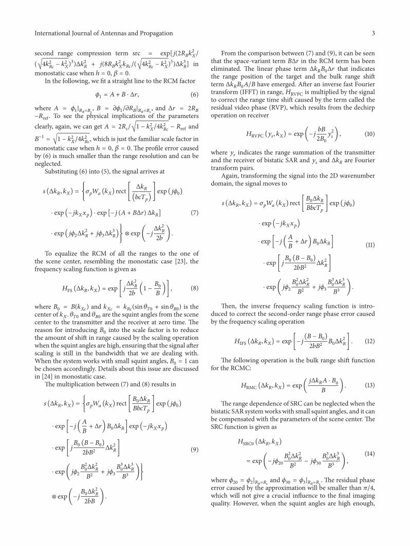
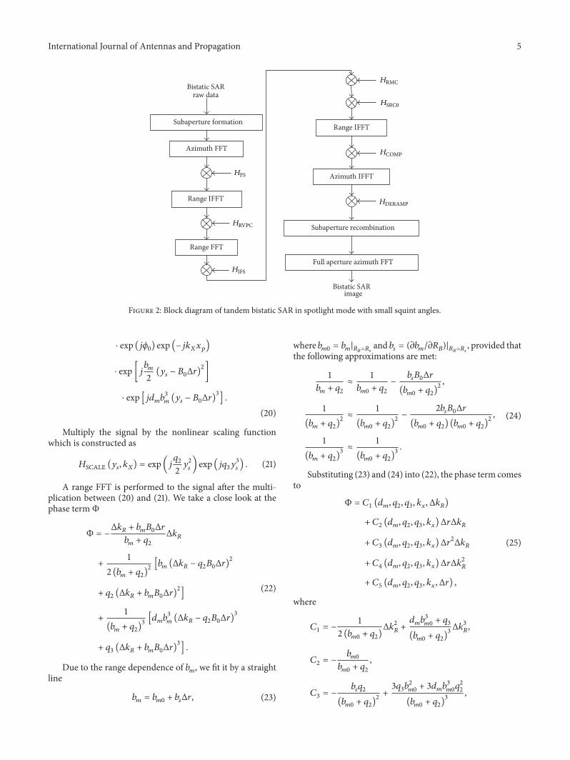
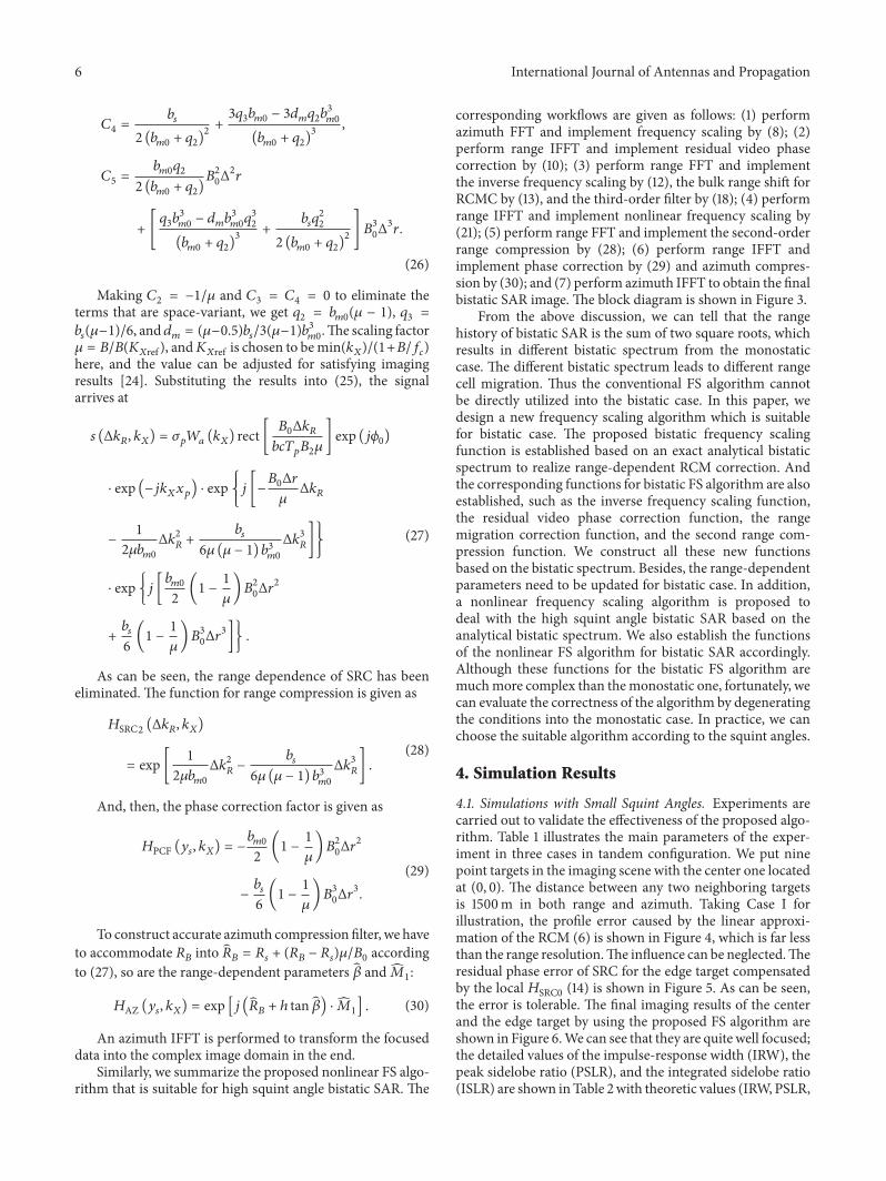
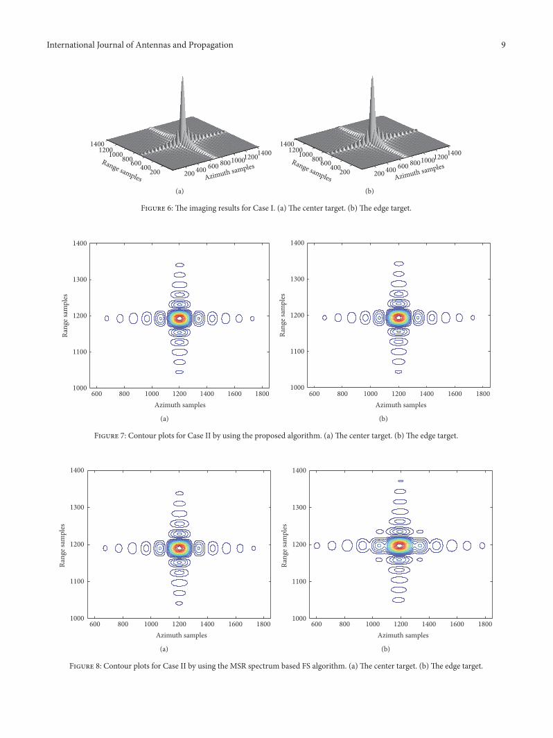
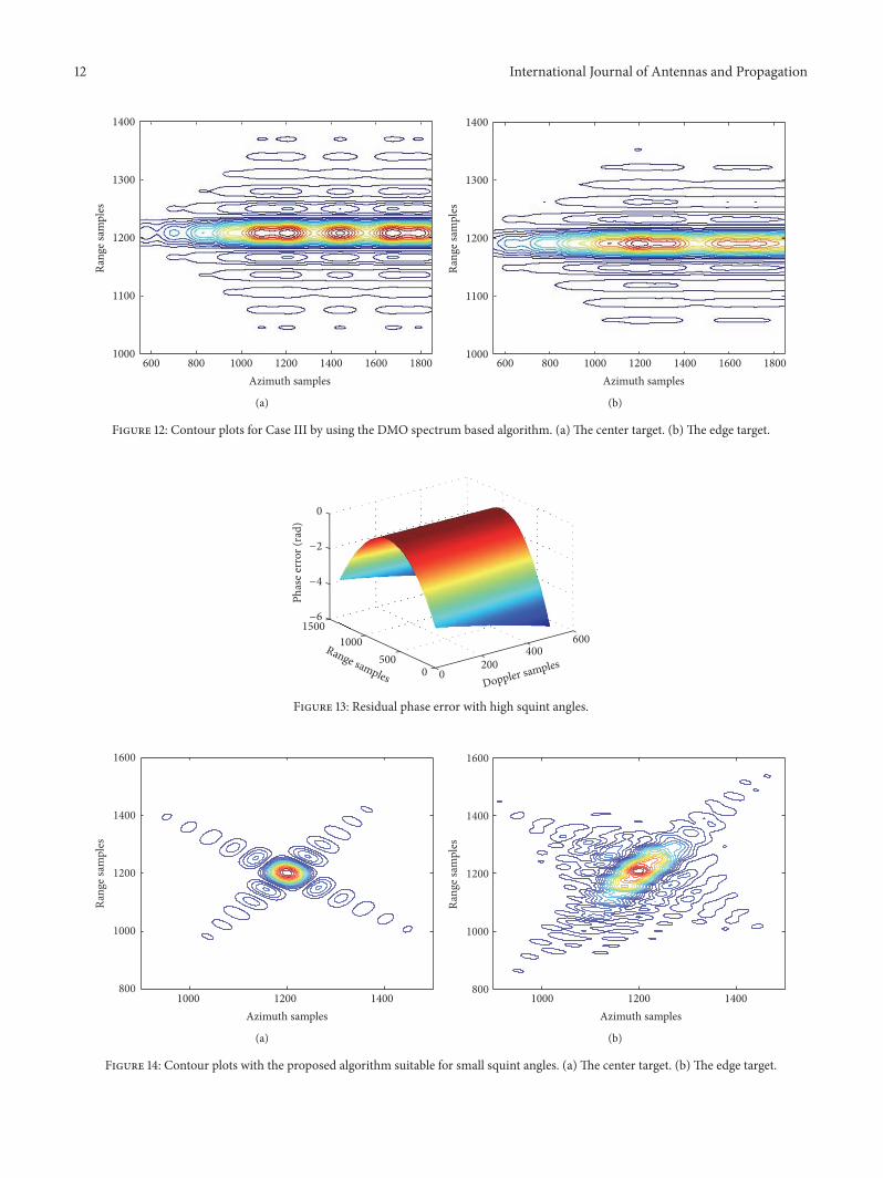
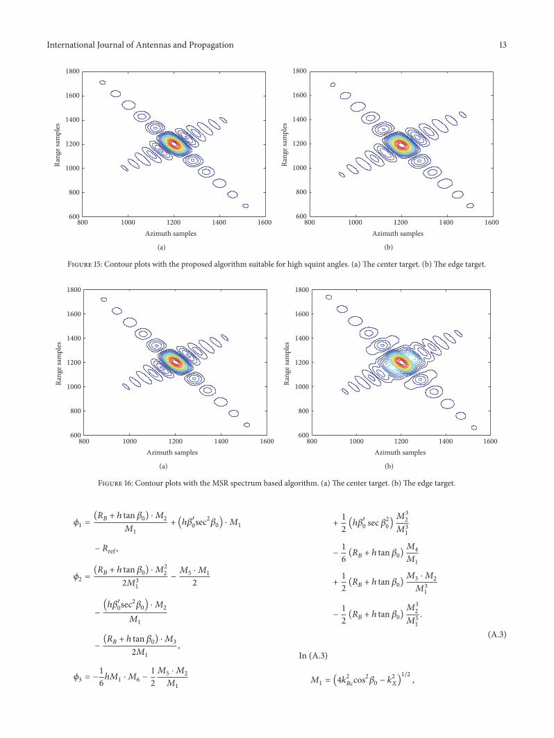

International Journal of
AerospaceEngineeringHindawi Publishing Corporationhttpwwwhindawicom Volume 2014
RoboticsJournal of
Hindawi Publishing Corporationhttpwwwhindawicom Volume 2014
Hindawi Publishing Corporationhttpwwwhindawicom Volume 2014
Active and Passive Electronic Components
Control Scienceand Engineering
Journal of
Hindawi Publishing Corporationhttpwwwhindawicom Volume 2014
International Journal of
RotatingMachinery
Hindawi Publishing Corporationhttpwwwhindawicom Volume 2014
Hindawi Publishing Corporation httpwwwhindawicom
Journal ofEngineeringVolume 2014
Submit your manuscripts athttpwwwhindawicom
VLSI Design
Hindawi Publishing Corporationhttpwwwhindawicom Volume 2014
Hindawi Publishing Corporationhttpwwwhindawicom Volume 2014
Shock and Vibration
Hindawi Publishing Corporationhttpwwwhindawicom Volume 2014
Civil EngineeringAdvances in
Acoustics and VibrationAdvances in
Hindawi Publishing Corporationhttpwwwhindawicom Volume 2014
Hindawi Publishing Corporationhttpwwwhindawicom Volume 2014
Electrical and Computer Engineering
Journal of
Advances inOptoElectronics
Hindawi Publishing Corporation httpwwwhindawicom
Volume 2014
The Scientific World JournalHindawi Publishing Corporation httpwwwhindawicom Volume 2014
SensorsJournal of
Hindawi Publishing Corporationhttpwwwhindawicom Volume 2014
Modelling amp Simulation in EngineeringHindawi Publishing Corporation httpwwwhindawicom Volume 2014
Hindawi Publishing Corporationhttpwwwhindawicom Volume 2014
Chemical EngineeringInternational Journal of Antennas and
Propagation
International Journal of
Hindawi Publishing Corporationhttpwwwhindawicom Volume 2014
Hindawi Publishing Corporationhttpwwwhindawicom Volume 2014
Navigation and Observation
International Journal of
Hindawi Publishing Corporationhttpwwwhindawicom Volume 2014
DistributedSensor Networks
International Journal of