research article pinning synchronization of linear...
TRANSCRIPT

Research ArticlePinning Synchronization of Linear ComplexCoupling Synchronous Generators Network ofHydroelectric Generating Set
Xuefei Wu
School of Computer Engineering, Shenzhen Polytechnic, Shenzhen 518055, China
Correspondence should be addressed to Xuefei Wu; [email protected]
Received 28 May 2014; Accepted 21 August 2014; Published 25 September 2014
Academic Editor: Chuandong Li
Copyright © 2014 Xuefei Wu. This is an open access article distributed under the Creative Commons Attribution License, whichpermits unrestricted use, distribution, and reproduction in any medium, provided the original work is properly cited.
A novel linear complex system for hydroturbine-generator sets in multimachine power systems is suggested in this paper andsynchronization of the power-grid networks is studied. The advanced graph theory and stability theory are combined to solve theproblem. Here we derive a sufficient condition under which the synchronous state of power-grid networks is stable in disturbanceattenuation. Finally, numerical simulations are provided to illustrate the effectiveness of the results by the IEEE 39 bus system.
1. Introduction
Types of grid electricity generation have thermal powergeneration types, hydropower, wind power, and solar photo-voltaic power generation, and there aremainly thermal powergeneration and hydropower in our country. Combined powergeneration is the problem the power plants are most con-cerned with in the power generation process. That is to say,power plants generating electricity need to be incorporatedinto the power grid to run.Asmost regional power supply andpower generation are separately controlled by power plantsand substations, power plants need to obey the scheduling,power supply bureau allowed the electricity are fed into thepower grid, power plants can generate electricity. After that,excess electricity can be used by other users and if electricitygenerated by plant power is insufficient, the large power inthe power grid can be used as a supplement. It would notbe that off-grid power and self-financing. So how to makeeach generator successful to incorporate into the power gridis vital to the stability of the power system in entire region.In general, combined power generation must meet severalrequirements: voltage equal; frequency stability; and samephase. Missing any of these conditions is likely to lead to lossof synchronization of the entire generator set and then spreadto the relevant local grid. Accordingly, this chapter focuses
on that when synchronous generators are subject to randomnoise, how to quickly return to a new equilibrium and tosynchronize again.
In the aspect of ensuring stability of the power system,power systems engineering experts and scholars have donea lot of research work, such as the authors of [1] discussthe self-synchronization of the power system and enhancedsynchronization capability approach; a novel nonequilibriumcomplete synchronization condition of dynamical smart gridwas proposed, whose results have improved synchronizationconditions in [2]. The authors of [3] studied synchronizationof the natural frequency bimodal distribution of complexpower networks, and derived synchronization coupling crit-ical condition. At the same time, the research results areapplied to the European interconnected high-voltage powersystems; literature [4] uses a coarse-grained scale model tostudy the self-organizing network synchronization powersystem model; they found that the more decentralized net-work of its dynamical behavior of nodes was, the more sensi-tive the randomdisturbancewas, themore robust its topologywas; literature [5] uses orthogonal decomposition methodand Galerkin method to explore New Zealand’s electricitynetwork global instability, which can help to predict the realglobal power network instability. Ph. D. thesis [6, 7] studiedthe conditions of the electricity network synchronization.
Hindawi Publishing CorporationMathematical Problems in EngineeringVolume 2014, Article ID 476794, 6 pageshttp://dx.doi.org/10.1155/2014/476794
2 Mathematical Problems in Engineering
u1
1 + Tss+
+
𝛼0
𝛼 1 − Tws
1 + 0.5Tws
Pm
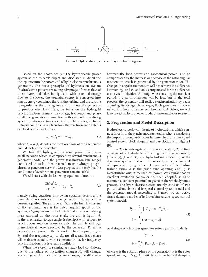
Figure 1: Hydroturbine speed control system block diagram.
Based on the above, we put the hydroelectric powersystem as the research object and discussed in detail theincorporate into the power grid of hydroelectric synchronousgenerators. The basic principles of hydroelectric system(hydroelectric power) are taking advantage of water flow ofthose rivers and lakes in high and with potential energyflow to the lower, the potential energy is converted intokinetic energy contained there in the turbine, and the turbineis regarded as the driving force to promote the generatorto produce electricity. Here, we focus on the hydrogridsynchronization, namely, the voltage, frequency, and phaseof all the generators connecting with each other realizingsynchronization and incorporating into the power grid. In thenetwork comprising 𝑛 alternators, the synchronization statuscan be described as follows:
𝑑1=
𝑑2= ⋅ ⋅ ⋅ =
𝑑𝑛, (1)
where 𝛿𝑖= 𝛿𝑖(𝑡) denotes the rotation phase of the 𝑖 generator
and ⋅ denotes time derivative.We take the hydrogroup in some power plant as a
small network which is composed by several synchronousgenerator (node) and the power transmission line (edge)connected to each other, referred to as hydrogroup syn-chronous generator network. Our purpose is to verify that theconditions of synchronous generators remain stable.
We will start with the following equation of motion:
2𝐻𝑖
𝜔𝑅
𝑑2𝛿𝑖
𝑑𝑡2
= 𝑃𝑚𝑖
− 𝑃𝑒𝑖, (2)
namely, swing equation. This swing equation describes thedynamic characteristics of the generator 𝑖 based on thecurrent equation. The parameters 𝐻
𝑖are the inertia constant
of the generator, 𝜔𝑅
is the rated angular speed of thesystem, 2𝐻
𝑖/𝜔𝑅means that all rotational inertia of rotating
mass attached on the rotor shaft, the unit is kg⋅m2; 𝛿𝑖
is the mechanical torque angle (subscript) with respect tosynchronous rotation reference axis, the unit is rad; 𝑃
𝑚𝑖
is mechanical power provided by the generator, 𝑃𝑒𝑖is the
generator load power in the network. In balance point, 𝑃𝑚𝑖
=
𝑃𝑒𝑖and the frequency 𝜔
𝑖≡
𝛿𝑖, for all 𝑖, and frequencies
will maintain equality with a constant; in (1), for frequencysynchronization, this is a valid condition.
When the system is running at steady load conditions,due to the failure or fluctuation changes 𝑃
𝑒𝑖will change.
According to (2), once the system changes, the difference
between the load power and mechanical power is to becompensated by the increase or decrease of the rotor angularmomentum which is generated by the generator rotor. Thechanges in angularmomentumwill not remove the differencebetween 𝑃
𝑚𝑖and 𝑃𝑒𝑖and only compensated for the difference
until synchronization. Although when entering the transientperiod, the synchronization will be lost, but in the totalprocess, the generator will realize synchronization by againadjusting its voltage phase angle; Each generator in powernetwork is how to realize synchronization? Below, we willtake the actual hydropowermodel as an example for research.
2. Preparation and Model Description
Hydroelectric work with the aid of hydroturbines which con-nect directly to the synchronous generator, when consideringthe impact of nonplastic water hammer, hydroturbine speedcontrol system block diagram and description is in Figure 1[9].
1 + 𝑇𝑠𝑠 is water-gate and the servo system, 𝑇
𝑠is time
constant of a hydroturbine opening control servo motor,(1 − 𝑇
𝑤𝑠)/(1 + 0.5𝑇
𝑤𝑠) is hydroturbine model, 𝑇
𝑤is the
diversion system inertia time constant, 𝑢 is the amountof input control, 𝛼
0is the reference value of the hydro-
turbine vanes, 𝛼 is the guide vane opening, and 𝑃𝑚
ishydroturbine output mechanical power. We assume that anexcellent excitation controller has been adopted, so as tomaintain a constant potential in 𝑞 axis in the whole dynamicprocess. The hydroelectric system mainly consists of twoparts, hydroturbine and its speed control system model andthe generator model. According to Figure 1, we can derivesingle dynamic model of hydroturbine and its speed controlsystem model:
��𝑚
=
2
𝑇𝑤
[−𝑃𝑚+ 𝛼 − 𝑇
𝑤��] ,
�� =
1
𝑇𝑠
(−𝛼 + 𝛼0+ 𝑢) .
(3)
And single synchronous generator rotor dynamic model is
𝛿 = 𝜔
�� =
𝜔𝑅
2𝐻
[𝑃𝑚− 𝑃𝑒− 𝐷𝜔] ,
(4)
where 𝛿 is the rotation phase of the generator, 𝜔 is the rotorspeed, and 𝜔
𝑅= 2𝜋𝑓
0, 𝑓0= 60Hz. 𝐷 is mechanical damping

Mathematical Problems in Engineering 3
coefficient,𝐻 is the inertia time constant of the rotor.𝑃𝑒is the
load power (the electric power of generator output), wherebywe can get four-order hydroelectric system dynamic model[5, 9]:
𝑑𝛿𝑖
𝑑𝑡
= 𝜔𝑖,
𝑑𝜔𝑖
𝑑𝑡
=
𝜋𝑓0
𝐻𝑖
{
{
{
− 𝐷𝑖𝜔𝑖+ 𝑃𝑚𝑖
− 𝐺𝑖𝑖𝐸𝑖
2
−
𝑛
∑
𝑗=1,𝑗 =𝑖
[𝐸𝑖𝐸𝑗𝐺𝑖𝑗cos (𝛿
𝑖− 𝛿𝑗)
+𝑆𝑖𝑗sin (𝛿
𝑖− 𝛿𝑗)]
}
}
}
,
𝑑𝑃𝑚𝑖
𝑑𝑡
=
2
𝑇𝑤𝑖
[−𝑃𝑚𝑖
+ 𝛼𝑖− 𝑇𝑤��𝑖] ,
𝑑𝛼𝑖
𝑑𝑡
=
1
𝑇𝑠𝑖
(−𝛼𝑖+ 𝛼0𝑖+ 𝑢𝑖) .
(5)
𝑥𝑖
= [𝛿𝑖, 𝜔𝑖, 𝑃𝑚𝑖, 𝛼𝑖] ∈ R4 is the state variable of the 𝑖
generator and 𝑓(𝑥𝑖, 𝑡) = [𝑓
1(𝑥𝑖), 𝑓2(𝑥𝑖), 𝑓3(𝑥𝑖), 𝑓4(𝑥𝑖)] : R4 ×
[0, +∞) → R4 is a continuous mapping as follows:
𝑓 (𝑥𝑖, 𝑡) =
{{{{{{{{{
{{{{{{{{{
{
𝜔𝑖
𝜋𝑓0
𝐻𝑖
[−𝐷𝑖𝜔𝑖+ 𝑃𝑚𝑖
− 𝐺𝑖𝑖𝐸𝑖
2]
2
𝑇𝑤𝑖
[−𝑃𝑚𝑖
+ 𝛼𝑖− 𝑇𝑤��𝑖]
1
𝑇𝑠𝑖
(−𝛼𝑖+ 𝛼0𝑖+ 𝑢𝑖) .
(6)
It is the dynamic equation of isolated nodes, denoting 𝑌𝑖𝑗
=
𝐺𝑖𝑗+ 𝑖𝐵𝑖𝑗as transmission circuit admittance, 𝐺
𝑖𝑗denotes the
transmit circuitry conductance, 𝑆𝑖𝑗denotes the susceptance,
and𝐸𝑖denotes the node voltage of the generator; based on the
above, hydroelectric generating set synchronous generatornetwork (5) can be rewritten as amore simple form as follows:
��𝑖(𝑡) = 𝑓 (𝑥
𝑖(𝑡) , 𝑡) +
𝑛
∑
𝑗= 1
𝑎𝑖𝑗Γ𝑥𝑗(𝑡)
+
𝑛
∑
𝑗= 1
𝑏𝑖𝑗Γ𝑥𝑗(𝑡) , 𝑖 = 1, . . . , 𝑛,
(7)
where 𝐴 = [𝑎𝑖𝑗] ∈ R𝑛×𝑛, when 𝑖 = 𝑗, then 𝑎
𝑖𝑗=
(𝜋𝑓0/𝐻𝑖) 𝐸𝑖𝐸𝑗𝐺𝑖𝑗cos 𝛿∗𝑖𝑗, 𝑎𝑖𝑗
= −∑𝑛
𝑗=1,𝑗 =𝑖𝑎𝑖𝑗, 𝑖, 𝑗 =
1, 2, . . . , 𝑛,𝐵 = [𝑏𝑖𝑗] ∈ R𝑛×𝑛, 𝑏
𝑖𝑗= (𝜋𝑓0/𝐻𝑖)𝐸𝑖𝐸𝑗𝑆𝑖𝑗sin 𝛿∗
𝑖𝑗, 𝑏𝑖𝑗=
−∑𝑛
𝑗=1,𝑗 =𝑖𝑏𝑖𝑗, 𝑖, 𝑗 = 1, 2, . . . , 𝑛 denote the network topology,
respectively. 𝛿∗𝑖𝑗denotes the phase differencewhile the system
is stable. Next, we will discuss the synchronization of hydro-electric generating set synchronous generator network (7). Toachieve synchronization, we add a node controller in the first
generator. So, hydroelectric generating set synchronous gen-erator network pinned control can be described as follows:
��1(𝑡) = 𝑓 (𝑥
1(𝑡) , 𝑡) + 𝑐
𝑛
∑
𝑗=1
𝑎1𝑗Γ𝑥𝑗(𝑡)
+ 𝑐
𝑛
∑
𝑗=1
𝑏1𝑗Γ𝑥𝑗(𝑡) − 𝑐𝜀Γ (𝑥
1(𝑡) − 𝑥 (𝑡)) ,
��𝑖(𝑡) = 𝑓 (𝑥
𝑖(𝑡) , 𝑡) + 𝑐
𝑛
∑
𝑗=1
𝑎𝑖𝑗Γ𝑥𝑗(𝑡)
+ 𝑐
𝑛
∑
𝑗=1
𝑏𝑖𝑗Γ𝑥𝑗(𝑡) , 𝑖 = 2, . . . , 𝑛,
(8)
where 𝑐 is the control strength and 𝑥(𝑡) = (1/𝑛)∑𝑛
𝑖=1𝑥𝑖(𝑡).
3. Synchronization Analysis of HydroelectricGenerating Set
In this section, we discuss pinning a hydroelectric generatingset synchronous generator network with linear delay irre-ducible symmetric coupling matrix.
Theorem 1. If hydroelectric generating set synchronous gener-ator network satisfied the condition as follows:
𝐼 ⊗ 𝐾 + 𝐴
𝑠
⊗ Γ + 𝐵𝑠⊗ Γ < 0, (9)
where 𝐴𝑆
= (𝐴 + 𝐴𝑇)/2, then the controlled hydroelectric
generating set synchronous generator network (8) can beglobally synchronized to 𝑥, where
𝐾 =
[
[
[
[
[
[
[
[
[
[
0 1 0 0
0 −
𝜋𝑓0𝐷𝑖
𝐻
𝜋𝑓0
𝐻
0
0 0 −
2
𝑇𝑤
2
𝑇𝑤
+
2
𝑇𝑠
0 0 0 −
1
𝑇𝑠
]
]
]
]
]
]
]
]
]
]
,
𝐴 = (𝑎𝑖𝑗)𝑛×𝑛
= 𝐴 − diag {(1 −
1
𝑛
) 𝜀, 0, . . . , 0} .
(10)
Proof. Define Δ𝑥𝑖(𝑡) = 𝑥
𝑖(𝑡) − 𝑥(𝑡). Because ∑𝑛
𝑗=1𝑎𝑖𝑗𝑥(𝑡) = 0,
we can easily get
𝑚
∑
𝑗=1
𝑎𝑖𝑗𝑥𝑗(𝑡) =
𝑚
∑
𝑗=1
𝑎𝑖𝑗Δ𝑥𝑗(𝑡) , (11)

4 Mathematical Problems in Engineering
so the error system of hydroelectric generating set syn-chronous generator network (8) of can be rewritten as
𝑑Δ𝑥1(𝑡)
𝑑𝑡
= 𝑓 (𝑥1(𝑡) , 𝑡) − 𝑓 (𝑥 (𝑡) , 𝑡) +
𝑛
∑
𝑗=1
𝑎1𝑗ΓΔ𝑥𝑗(𝑡)
+
𝑛
∑
𝑗=1
𝑏1𝑗ΓΔ𝑥𝑗(𝑡) − (1 −
1
𝑛
) 𝜀ΓΔ𝑥1(𝑡) + 𝐽,
𝑑Δ𝑥𝑖(𝑡)
𝑑𝑡
= 𝑓 (𝑥𝑖(𝑡) , 𝑡) − 𝑓 (𝑥 (𝑡) , 𝑡) +
𝑛
∑
𝑗=1
𝑎𝑖𝑗ΓΔ𝑥𝑗(𝑡)
+
𝑛
∑
𝑗=1
𝑏𝑖𝑗ΓΔ𝑥𝑗(𝑡) + 𝐽, 𝑖 = 2, . . . , 𝑛,
(12)
where, 𝐽 = 𝑓(𝑥(𝑡), 𝑡) − (1/𝑛)∑𝑛
𝑖=1𝑓(𝑥𝑖(𝑡), 𝑡).
Take Lyapunov function
𝑉 (𝑡) =
1
2
𝑛
∑
𝑖=1
Δ𝑥𝑇
𝑖(𝑡) Δ𝑥
𝑖(𝑡) (13)
and define Δ𝑥(𝑡) = (Δ𝑥𝑇
1(𝑡), . . . , Δ𝑥
𝑇
𝑛(𝑡))𝑇, 𝑖 = 1, . . . , 𝑛. Now
we calculate
�� (𝑡) |(12)
=
𝑛
∑
𝑖=1
Δ𝑥𝑇
𝑖(𝑡)
×[
[
𝑓 (𝑥𝑖(𝑡) , 𝑡) − 𝑓 (𝑥 (𝑡) , 𝑡)
+
𝑛
∑
𝑗=1
𝑎𝑖𝑗ΓΔ𝑥𝑗(𝑡) +
𝑛
∑
𝑗=1
𝑏𝑖𝑗ΓΔ𝑥𝑗(𝑡) + 𝐽
]
]
=
𝑛
∑
𝑖=1
Δ𝑥𝑇
𝑖(𝑡) 𝐾Δ𝑥
𝑖(𝑡)
+
𝑛
∑
𝑖=1
Δ𝑥𝑇
𝑖(𝑡)
𝑛
∑
𝑗=1
𝑎𝑖𝑗ΓΔ𝑥𝑗(𝑡)
+
𝑛
∑
𝑖=1
Δ𝑥𝑇
𝑖(𝑡)
𝑛
∑
𝑗=1
𝑏𝑖𝑗ΓΔ𝑥𝑗(𝑡)
= Δ𝑥𝑇(𝑡) (𝐼 ⊗ K) Δ𝑥 (𝑡) + Δ𝑥
𝑇(𝑡) (𝐴 ⊗ Γ)Δ𝑥 (𝑡)
+ Δ𝑥𝑇(𝑡) (𝐵 ⊗ Γ) Δ𝑥 (𝑡)
= Δ𝑥𝑇(𝑡) (𝐼 ⊗ 𝐾 + 𝐴 ⊗ Γ + 𝐵 ⊗ Γ)Δ𝑥 (𝑡) .
(14)
We know, based onTheorem 1, that 𝐴 is negative definitematrix; obviously, the condition (9) can be satisfied easily;therefore, we can get ��(𝑡) < 0. Theorem 1 is proved.
Remark 2. If the hydroelectric generating set synchronousgenerator networkmeet the condition 𝐼⊗𝐾+𝐴
𝑆
⊗Γ+𝐵𝑆⊗Γ < 0,
15
5 12
1110
78
9
4
3
12
1718
14
16
1920
21
24
2627
28
31
3234 33
36
38
39 2235
613
303725
29
23
1
108
2
3
6
9
47
5
Figure 2: Grid network structure (which is generator nodesconnected with circle, a total of 10, and the remaining nodes arenongenerator nodes. [2, 8]).
Figure 3: Network topology after simplifying Figure 2 by usingKronmethod (the 10 red nodes in the figure are the generator nodes,all links between the generator nodes. [2]).
then the controlled hydroelectric generating set synchronousgenerator network (8) can be globally synchronized.Here, thesynchronization of network is decided by electric system itselfand the network structure.
4. Numerical Simulation
Numerical simulation of this section, we mainly considerIEEE 39 test grid (data using 100MVA, 60Hz) [8], as shownin Figure 2 andTable 1. Figure 3 showsnetwork topology aftersimplifying Figure 2 by using Kron method.
In the numerical experiments, let the nominal angularvelocity 𝜔
0= 60Hz, the reference value of hydroturbine
guide vanet 𝛼0= 1, the mechanical damping coefficient 𝐷 =
0.5, rotor inertia time constant𝐻 = 4, inertia time constant ofdiversion system 𝑇
𝑤= 4, and hydroturbine opening control
servo motor time constant 𝑇𝑠
= 4. In this paper, we let 𝑢be 0, we can verify it satisfies theorem. Each of the generator

Mathematical Problems in Engineering 5
Table 1: P.S. IEEE39 power network node admittance.
𝑖 𝑗 𝑦𝑖𝑗
1 2 0.0035 + 0.0411𝑖1 39 0.0020 + 0.050𝑖2 3 0.0013 + 0.0151𝑖2 25 0.0070 + 0.0086𝑖3 4 0.0013 + 0.0213𝑖3 18 0.0011 + 0.0133𝑖4 5 0.00080 + 0.0128𝑖4 14 0.00080 + 0.0129𝑖5 6 0.00020 + 0.0026𝑖5 8 0.00080 + 0.0112𝑖6 7 0.00060 + 0.0092𝑖6 11 0.00070 + 0.0082𝑖7 8 0.00040 + 0.0046𝑖8 9 0.0023 + 0.0363𝑖9 39 0.0010 + 0.025𝑖10 11 0.00040 + 0.0043𝑖10 13 0.00040 + 0.0043𝑖13 14 0.00090 + 0.0101𝑖14 15 0.0018 + 0.0217𝑖15 16 0.00090 + 0.0094𝑖16 17 0.00070 + 0.0089𝑖16 19 0.0016 + 0.0195𝑖16 21 0.00080 + 0.0135𝑖16 24 0.00030 + 0.0059𝑖17 18 0.00070 + 0.0082𝑖17 27 0.0013 + 0.0173𝑖21 22 0.00080 + 0.014𝑖22 23 0.00060 + 0.0096𝑖23 24 0.0022 + 0.035𝑖25 26 0.0032 + 0.0323𝑖26 27 0.0014 + 0.0147𝑖26 28 0.0043 + 0.0474𝑖26 29 0.0057 + 0.0625𝑖28 29 0.0014 + 0.0151𝑖2 30 0.0181𝑖6 31 0.050𝑖6 31 0.0 + 0.050𝑖10 32 0.0 + 0.020𝑖12 11 0.0016 + 0.0435𝑖12 13 0.0016 + 0.0435𝑖19 20 0.00070 + 0.0138𝑖19 33 0.00070 + 0.0142𝑖20 34 0.00090 + 0.018𝑖22 35 0.0 + 0.0143𝑖23 36 0.00050 + 0.0272𝑖25 37 0.00060 + 0.0232𝑖29 38 0.00080 + 0.0156𝑖
initial speed is randomly generated by the computer (attachedgenerator admittance between nodes); using the function
0 1 2 3 4 50
50
100
150
200
250
300
t
𝛿i
Figure 4: The evolution process of pinning the rotor phase of 10generator nodes.
0 1 2 3 4 50
10
20
30
40
50
60
70
t
𝜔i(t)
Figure 5: The evolution process of pinning the rotor frequency of10 generator nodes.
ode45 in MATLAB solve (7), we can obtain the numericalresults of the individual states for each node.
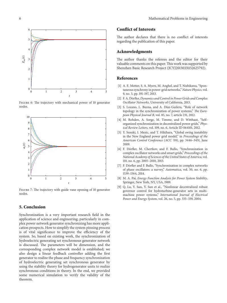
Figures 4 and 5 are evolution schematic diagrams withhydroelectric generating set synchronous generator networkof 10 generator nodes, generator rotor phase, and the rotorfrequency. Figures 6 and 7 are mechanical power for thegenerator and the guide vane opening states. From the figures,we can obviously find that all the generators are synchronizedwhich indicate that the algorithm described in this chapter isvalid to achieve synchronization of hydroelectric generatingset synchronous generator network.
6 Mathematical Problems in Engineering
0 1 2 3 4 50
1
2
3
4
5
6
t
Pmi(t)
Figure 6: The trajectory with mechanical power of 10 generatornodes.
0 1 2 3 4 50
1
2
3
4
5
6
7
8
9
10
t
𝛼i(t)
Figure 7: The trajectory with guide vane opening of 10 generatornodes.
5. Conclusion
Synchronization is a very important research field in theapplication of science and engineering; particularly in com-plex power network generator synchronizing has more appli-cation prospects. How to simplify the system pinning processis of vital significance to improve the efficiency of thesystem. So, based on existing work, the synchronization ofhydroelectric generating set synchronous generator networkis discussed. The parameters will be dimension, and thecorresponding complex network model is established; wealso design a linear feedback controller adding the firstgenerator to realize the phase and frequency synchronizationof hydroelectric generating set synchronous generator byusing the stability theory for hydrogenerator units to realizesynchronous conditions in theory. In the end, we providedsome numerical simulation to verify the validity of thetheorem.
Conflict of Interests
The author declares that there is no conflict of interestsregarding the publication of this paper.
Acknowledgments
The author thanks the referees and the editor for theirvaluable comments on this paper.Thisworkwas supported byShenzhen Basic Research Project (JCYJ20130331152625792).
References
[1] A. E. Motter, S. A. Myers, M. Anghel, and T. Nishikawa, “Spon-taneous synchrony in power-grid networks,”Nature Physics, vol.9, no. 3, pp. 191–197, 2013.
[2] F. A.Dorfler,Dynamics andControl in PowerGrids andComplexOscillator Networks, University of California, 2013.
[3] S. Lozano, L. Buzna, and A. Dıaz-Guilera, “Role of networktopology in the synchronization of power systems,” The Euro-pean Physical Journal B, vol. 85, no. 7, article 231, 2012.
[4] M. Rohden, A. Sorge, M. Timme, and D. Witthaut, “Self-organized synchronization in decentralized power grids,” Phys-ical Review Letters, vol. 109, no. 6, Article ID 064101, 2012.
[5] Y. Susuki, I. Mezic, and T. Hikihara, “Global swing instabilityin the New England power grid model,” in Proceedings of theAmerican Control Conference (ACC ’09), pp. 3446–3451, June2009.
[6] F. Dorfler, M. Chertkov, and F. Bullo, “Synchronization incomplex oscillator networks and smart grids,” Proceedings of theNational Academy of Sciences of theUnited States of America, vol.110, no. 6, pp. 2005–2010, 2013.
[7] F. Dorfler and F. Bullo, “Synchronization in complex networksof phase oscillators: a survey,” Automatica, vol. 50, no. 6, pp.1539–1564, 2014.
[8] M. A. Pai, Energy Function Analysis for Power System Stability,Springer, New York, NY, USA, 1989.
[9] Q. Lu, Y. Sun, Y. Sun et al., “Nonlinear decentralized robustgovernor control for hydroturbine-generator sets in multi-machine power systems,” International Journal of ElectricalPower and Energy System, vol. 26, no. 5, pp. 333–339, 2004.

Submit your manuscripts athttp://www.hindawi.com
Hindawi Publishing Corporationhttp://www.hindawi.com Volume 2014
MathematicsJournal of
Hindawi Publishing Corporationhttp://www.hindawi.com Volume 2014
Mathematical Problems in Engineering
Hindawi Publishing Corporationhttp://www.hindawi.com
Differential EquationsInternational Journal of
Volume 2014
Applied MathematicsJournal of
Hindawi Publishing Corporationhttp://www.hindawi.com Volume 2014
Probability and StatisticsHindawi Publishing Corporationhttp://www.hindawi.com Volume 2014
Journal of
Hindawi Publishing Corporationhttp://www.hindawi.com Volume 2014
Mathematical PhysicsAdvances in
Complex AnalysisJournal of
Hindawi Publishing Corporationhttp://www.hindawi.com Volume 2014
OptimizationJournal of
Hindawi Publishing Corporationhttp://www.hindawi.com Volume 2014
CombinatoricsHindawi Publishing Corporationhttp://www.hindawi.com Volume 2014
International Journal of
Hindawi Publishing Corporationhttp://www.hindawi.com Volume 2014
Operations ResearchAdvances in
Journal of
Hindawi Publishing Corporationhttp://www.hindawi.com Volume 2014
Function Spaces
Abstract and Applied AnalysisHindawi Publishing Corporationhttp://www.hindawi.com Volume 2014
International Journal of Mathematics and Mathematical Sciences
Hindawi Publishing Corporationhttp://www.hindawi.com Volume 2014
The Scientific World JournalHindawi Publishing Corporation http://www.hindawi.com Volume 2014
Hindawi Publishing Corporationhttp://www.hindawi.com Volume 2014
Algebra
Discrete Dynamics in Nature and Society
Hindawi Publishing Corporationhttp://www.hindawi.com Volume 2014
Hindawi Publishing Corporationhttp://www.hindawi.com Volume 2014
Decision SciencesAdvances in
Discrete MathematicsJournal of
Hindawi Publishing Corporationhttp://www.hindawi.com
Volume 2014 Hindawi Publishing Corporationhttp://www.hindawi.com Volume 2014
Stochastic AnalysisInternational Journal of