research article power control for direct-driven...
TRANSCRIPT

Research ArticlePower Control for Direct-Driven Permanent Magnet WindGenerator System with Battery Storage
Chu Xiao Guang1 and Kong Ying2
1 School of Electrical Information Automation QuFu Normal University Rizhao 276826 China2 School of Medical Information and Technology Jining Medical University Rizhao 276826 China
Correspondence should be addressed to Kong Ying kongying jn126com
Received 17 April 2014 Accepted 31 May 2014 Published 19 June 2014
Academic Editor Wei Wan
Copyright copy 2014 C X Guang and K Ying This is an open access article distributed under the Creative Commons AttributionLicense which permits unrestricted use distribution and reproduction in any medium provided the original work is properlycited
The objective of this paper is to construct a wind generator system (WGS) loss model that addresses the loss of the wind turbine andthe generator It aims to optimize themaximum effective output power and turbine speed Given that the wind generator system hasinertia and is nonlinear the dynamic model of the wind generator system takes the advantage of the duty of the Buck converter andemploys feedback linearization to design the optimized turbine speed tracking controller and the load power controller Accordingto that this paper proposes a dual-mode dynamic coordination strategy based on the auxiliary load to reduce the influence of modeconversion on the lifetime of the battery Optimized speed and power rapid tracking as well as the reduction of redundant powerduring mode conversion have gone through the test based on a 5 kW wind generator system test platform The generator outputpower as the capture target has also been proved to be efficient
1 Introduction
With the depletion of resources and environment newenergy has become a focus for global economic growthand sustainable development Extensive research has beenfocused to advance the technologies of power generationsystems based on various renewable sources such as solarenergy geothermal biomass fuel cell and industrial wasteheat [1ndash4] Wind power is gaining momentum because it ispollution-free and abundant and moves to small-scale andlarge-scale development [5]
Small-scale wind turbine system is flexible and less invest-ment It is widely used to provide power for areas with loosesettlement and abundant wind resources [6 7] However thefluctuation and intermittence of wind frequently result insystem power to be imbalanced Currently battery is usedto address such imbalance But the lifespan of a battery is2-3 years much shorter than a generator or a wind turbinechallenging the cost of wind power generation Usuallythe battery is in the state of overcharge and discharge [8ndash10] Limited by voltage of battery wind turbine cannot be
employed to the best Thus a low power coefficient and theshort life of the battery are crucial problems faced with small-scale wind power generators [11ndash13]
Wind energy capture has always been a hot issue inresearches on wind power generation Two widely acceptedmethods are tip speed ratio control andpower signal feedbackcontrol [11 14ndash20]The best tip speed ratio and themaximumpower can be concluded from the power curve provided byproducers The controlling target is clear and the algorithmis easy But the capture power does not equal effective outputpower because of losses in mechanical drive and generatorin particular under large load Loss in generator will makethe effective output power derived from the power curveAnother is the hill-climbing searching method based onthe generator output power It can realize the maximumeffective output power control but it cannot achieve themaximum power point tracking speed and the minimummechanical impact at the same time A focus on searchingspeed will unavoidably enhance the mechanical impact Afocus on tracking accuracymay lead to a slow searching speed[19 21ndash26] The abovementioned methods fail to consider
Hindawi Publishing Corporatione Scientific World JournalVolume 2014 Article ID 962374 9 pageshttpdxdoiorg1011552014962374
2 The Scientific World Journal
the nonlinear large inertia and fluctuated nature of the windgenerator system Therefore this paper hopes to optimizethe maximum effective output power and turbine speed andfurther optimize the maximum output power point trackingby constructing a wind generator system loss model
In fact wind turbines cannot always be working on themaximum power tracking Because of the dynamic change ofload and battery thewind generator systemmust be equippedwith maximum power tracking and the accurate powercontrolling function To improve the lifetime of the batterythese two functions are corresponding to two operationalmodes of the maximum power tracking and the accuratepower controlling Given that the inertia of wind turbinesresults in a slow reaction this paper adopts the feedbacklinearization to design the tracking controller in order toenhance the dynamic tracking speed As mode conversionis frequent and excess power during the conversion willovercharge the battery [27] this paper proposes a dual-modedynamic coordination strategy based on auxiliary load
2 Principles of WGS with Battery
TheWGS with battery storage is shown in Figure 1 includingwind turbine permanent magnet generator uncontrolledrectifier Buck converter battery storage and auxiliary loadBuck converter is for adjusting the turbine speed and chang-ing the operation of the wind turbine Battery storage systemmanages the charge and discharge by Buck-boost converterAuxiliary load is mainly for dynamic coordination of modeconversion and for eliminating the excess power duringmodeconversion
Because of the dynamic change of the wind speed andthe load power the system is able to operate two operationalmodes of the maximum power tracking and power control-ling The maximum power tracking is improved on the basisof traditional capture power curve The tracking strategy isbased on effective generator output power When the outputpower exceeds the load or the maximum charge power of thebattery the systemwill switch to the power controllingmode
The coordinating controller selects the operational modeof the wind generator system according to real-time windspeed load and the state of the battery Given the largeinertia and the slow response this paper proposes a dual-mode dynamic coordination strategy based on auxiliary loadto effectively address the imbalanced power during modeconversion
3 Wind Generator System Model
31 Wind Turbine Model Small-scale wind turbine usuallyhas fixed pitches and stall-control automatically conducted byblades It faces the wind by rear controlThe capture power ofthe wind turbine and the torque can be expressed as
119875119908=1
21205881205871198772
1198813
119879wind =1
21205881205871198773
1198812
(1)
V
PMSGis
Rectifier Buck Inverter
Load
Buck-boost
Battery storage system
Maximum powertracking mode
Power regulationmode
Coordinatingcontroller
+
minusminus
dd
PI
C0 Rd
ud
ux
uref
udc
udc
V iL IBUbUb
Ib
Idc iL
C1
Figure 1 Sketch map of the WGS with battery storage
In the expression 120588 refers to air density kgm3 119877 is theradius of the blade m and 119881 refers to wind speed ms
Many kinds of losses in the wind turbine result in a loweffective capture power The maximum coefficient of windenergy is only 0593 The torque of the loss can be expressedas [13]
119879loss = 11989601198812
+ 1198961119881120596 + 119896
21205962
(2)
where 120596 refers to turbine speed radsec 1198960sim 1198962refer to loss
parameters decided by the nature of the turbineThe effective capture torque is expressed as
119879119908= 119879wind minus 119879loss (3)
32 Permanent Magnet Generator Model The generatortransmits the power through noncontrolled rectifier andBuck converter And the Buck converter makes it possible toachieve the maximum capture of the effective output powerby adjusting the turbine speed
The electromagnetic torque of the generator and theelectromotive force can be expressed as
119879119892= 119896119892119894119904 (4)
where 119894119904is the stator current of the generator A Consider
119864 = 119896119890120596 (5)
The phase voltage of the generator is expressed as
119880119904= 119864 minus 119871
119904
119889119894119904
119889119905minus 119877119904119894119904 (6)
In the expression 119896119892and 119896
119890are torque coefficient and
the electromotive force coefficient respectively 119871119904and119877
119904are
stator inductance and internal resistanceBecause the dynamic response of the turbine is slower
than the battery storage system the voltage119880dc is consideredas constant 119880
119904is expressed as
119880119904=120587119880dc
3radic3
119906119909 (7)
If we neglect the loss of converter the DC output currentof the generator is expressed as
119868dc =120587
2radic3
119894119904119906119909 (8)
The Scientific World Journal 3
33 Battery Storage SystemModel Thebattery storage systemis shown in Figure 2 Buck-boost converter is responsible forcharge and discharge and stabilizing theDCbus voltageThenthe dynamic function of the DC output current is expressedas
119862dc119889119880dc119889119905
= 119868dc minus 119868119861 minus 119868119871 (9)
In the expression119862dc refers to the capacitance119865 119868119871 refersto DC load current and 119868
119861refers to current at the high-
voltage side AThe battery model is expressed as [28]
119906119887= 119906oc minus 119894119887119877119887 (10)
In the expression 119894119887 119906119887 119906oc and 119877
119887are the battery
current terminal voltage open circuit voltage and internalresistance
If we neglect the power loss of Buck-boost converter wecan get
119894119887=
119880dc119868119861119899 (119880oc minus 119894119887119877119887)
(11)
To prevent the influence of overcharge and discharge onthe lifetime of the battery the voltage and the currentmust belimited to
119880119887isin [119880min 119880max]
119894bcmax = 01119862 119894bdmax = 03119862
(12)
In the expression 119880max and 119880min are the upper limit andlower limit of the voltage 119862 refers to the battery capacity119894bcmax and 119894bdmax are the maximum value of charge anddischarge respectively
Because of the dynamic change of the wind speed and theload Buck-boost converter can operate two modes namelyBuck and boost When 119868dc minus119868119871 ge 0 and when 119894bc le 119894bcmax and119880119887le 119880max1198762 is off and the DC bus voltage is made constant
through 1198761duty which is the Buck mode when 119868dc minus 119868119871 le 0
119894119887le 119894bdmax and 119880min le 119880
119887 1198761is off and the DC bus voltage
is made constant through 1198762duty which is the boost mode
34 Wind Generator System Dynamic Model Suppose theangular speed and the phase current are state variables wecan get the wind generator system dynamic model fromexpressions (2)sim(8) taking the duty 119906
119909of Buck converter as
the input Consider
119889120596
119889119905=
1
119869119908
(1
21205881205871198773
1198812
minus 11989601198812
minus 1198961119881120596 minus 119896
21205962
minus 119896119892119894119904)
119889119894119904
119889119905= 119896119890120596 minus
119877119904119894119904
119871119904
minus120587119906dc
3radic3119871119904
119906119909
(13)
In the expression 119869119908refers to moment of inertia
Battery Buck-boost
Generator
load
Q1
Lib
nUoc
nRb
Q2
Idc
Cdc
Udc
IL
IB
+
Figure 2 Equivalent circuit of the battery storage system
4 Maximum Effective GeneratorPower Optimization
Wind energy capture is decided by power curve provided byproducers But the power curve only indicates the capturepower of the turbine rather than effective generator outputpower As a matter of fact losses in turbines do influencethe effective capture power and should be considered in theoptimized solution to achieve the effective output power andthe turbine speed
The turbine loss power and generator loss power areexpressed as
119875119908loss = 119879loss120596 + 119875cu + 119875Fe (14)
In the expression 119875cu = 31198942
119904119877119904 119875Fe asymp 119864
2
119877119891
= (119896119890120596)2
119877119891 119877119891is Core loss equivalent resistance
From expressions (2) (3) (13) and (14) it is easy to getthe optimized function for turbine losses
119869 = 11989111205964
+ 11989121205963
+ 11989131205962
+ 1198914120596 + 1198915
st 0 le 120596 le 120596max(15)
In the expression
1198911= minus
1198771199041198962
2
1198962119892
1198912= minus1198962minus211989611198962119877119904119881
1198962119892
1198913= minus1198961119881 minus
1198962
119890
119877119891
+
(21198861198962119877119904minus 1198962
11198771199041198812
minus 2119896011989621198771199041198812
)
1198962119892
1198914= 119886 minus 119896
01198812
+
(21198861198961119877119904119881 minus 2119896
011989611198771199041198813
)
1198962119892
1198915=
(211988611989601198771199041198812
minus 1198862
119877119904minus 11989601198771199041198814
)
1198962119892
119886 = 051205881205871198773
1198812
(16)
4 The Scientific World Journal
By 119889119869119889120596 = 0 120596op can be acquired by
119891 (120596op) = 41198911120596op3
+ 31198912120596op2
+ 21198913120596op + 1198914 = 0 (17)
By Newton-Raphson method there is
120596op (119899 + 1) = 120596op (119899) minus119891 (120596op (119899))
1198911015840 (120596op (119899))
st 1198911015840 (120596op (119899)) = 121198911120596op(119899)
2
+ 61198912120596op (119899) + 2119891
3
(18)
The maximum effective generator output power is
119875119892(120596op) = 119875
119908(120596op) minus 119875119908loss (120596op) (19)
Figure 3 shows the power curve of 5 kW turbines (pro-vided by producers) and the relationship between the gener-ator output power and the optimized turbine speed As thewind velocity increases the wind turbine mechanical power(more load) is deviated from the optimized generator outputpower and both curves have the same trend
5 Dual-Mode Power Control for WGS
The maximum effective power tracking mode (Mode I) andpower regulation mode (Mode II) are shown in Figure 4The coordinating controller selects operational modes andcompletes mode conversion Given the big inertia of theturbine and the slow response to the mode conversionin particular when it switches from Mode I to Mode IIthere is unavoidably excessive powerTherefore a dual-modedynamic coordination strategy based on auxiliary load isproposed to reduce the influence of conversion
Mode I The battery is in the safety area The voltage is119880119887isin [119880min 119880max] and the current is 119894
119887isin [119894bdmax 119894bcmax]
The turbine works in the maximum effective output powercapture zone The battery storage system in accordance withthe change of thewind speed and load power operates at Buckcharge or Boost discharge that is
Buck Charge 119875119908ge 119875119871 0 le 119894
119887le 119894bcmax
Boost Discharge 119875119908le 119875119871 119894bdmax le 119894
119887lt 0
(20)
Mode II When the terminal voltage or the charge currentexceeds safety limits that is when 119880
119887ge 119880max or 119894
119887ge
119894bcmax the system will switch to the power controlling modeUnder such mode the turbine will operate for the purpose ofreaching the maximum sum of charge power and load powerand will reduce the capture power This is at Buck modeSuppose the standard power is 119875
119908= 119881dc (119868119871 + 119868
119887ref) In theexpression 119868
119887ref refers to the maximum charge current
51 Maximum Effective Power Tracking Mode The windgenerator system dynamic model can be converted to [29]
= 119891 (119909) + 119892 (119909) 119906 119910 = ℎ (119909) (21)
10 12 14 16 18 20 22 24 26 280
1
2
3
4
5
6
Turbine speed (rads)
Pow
er (k
W)
Optimized generator output power
Wind turbine mechanical power with optimum Cpmax
Figure 3 Relation of wind mechanical power and the optimizedgenerator effective power with the turbine speed
In the expression
119891 (119909) =
[[[
[
119896119890120596 minus
119877119904119894119904
119871119904
1
119869119908
(051205881205871198773
1198812
minus 11989601198812
minus 1198961119881120596 minus 119896
21205962
minus 119896119892119894119904)
]]]
]
119892 (119909) = [
[
minus120587119880dc
3radic3119871119904
0
]
]
ℎ (119909) = 120596
(22)
Take the optimized turbine speed as output based onthe linearization method of input and output to design thecontroller Consider
119910 = 119871119891ℎ (119909) + 119871
119892ℎ (119909) 119906
=1
119869119908
(051205881205871198773
1198812
minus 11989601198812
minus 1198961119881120596 minus 119896
21205962
minus 119896119892119894119904)
(23)
As 119871119892ℎ(119909) = 0 calculate the derivation of 119910 and get
119910 = 119871119891119910 + 119871119892119910119906 = 119860
1(119905) + 119864
1(119905) 119906119909 (24)
In the expression
1198601(119905) = minus
1
119869119908
(119896119892119896119890120596 minus
119896119892119877119904119894119904
119871119904
) minus1
1198692119908
(119896119890119881 + 2119896
2120596)
times (051205881205871198773
1198812
minus 11989601198812
minus 119896119892119894119904minus 1198961119881120596 minus 119896
21205962
)
1198641(119905) =
120587119880dc
3radic3119869119908119871119904
gt 0
(25)
Let 119910 = V there is the second-order linear system with Vas the input The transfer function is 119866(119904) = 1119904
2Given that the system is unstable the tracking controller
with optimized speed based on feedback linearization isshown in Figure 5 Consider
V = 119910 = = 1198964(120596ref minus 120596) minus 1198965 (26)
The Scientific World Journal 5
Mode I maximum power tracking
Buck chargeBoost discharge
Mode II power regulation
Pw =
Pw lt PL
Pw = Pw
PL le Pw
Pw = Vdc(IL + Ibref)
Ibref = Ibcmax
maxPwmax
Figure 4 Schematic description of the operational modes
+minus
+
minus
120596opk4
k5
w w 120596w1s 1s
Figure 5 Optimized speed tracking controller
The transfer function of closed-loops system is expressedby
119866 (119904) =1198964
1199042 + 1198965119904 + 1198964
(27)
According to Routh criterion the system stability shouldmeet 119896
4gt 0 119896
5gt 0
To ensure a stable operation and enhance the integralterm for the turbine speed tracking controller there is
V = 1198964119890 minus 1198965119890 + 119896119887int 119890119889119905
119906119909=
1198964119890 minus 1198965119890 + 119896119887int 119890119889119905 minus 119860
1(119905)
1198641(119905)
(28)
In the expression 119890 = 120596 minus 120596op
52 Power Controlling Mode When the generator outputpower exceeds load power and when the charge currentexceeds the safety limits the system switches from themaximum power tracking mode to power controlling modeand reduces wind energy capture
Take the generator output power as output and apply thewind generator system mode (21) to feedback linearizationConsider
ℎ (119909) = 119875119892= 119896119892119894119904120596119908minus 31198942
119904119877119904
119910 =120597ℎ
120597119909[119891 (119909) + 119892 (119909) 119906] = 119860
2(119905) + 119864
2(119905) 119906
(29)
In the expression
1198602(119905) = (119896
119892120596 minus 6119877
119904119894119904) (119896119890120596 minus
119877119904119894119904
119871119904
)
+
119896119892119894119904
119869119908
(051205881205871198773
1198812
minus 11989601198812
minus 119896119892119894119904minus 1198961119881120596 minus 119896
21205962
)
1198642(119905) = (119896
119892120596 minus 6119877
119904119894119904)120587119880dc
3radic3119871119904
gt 0
(30)
Let 119910 = V2 here is the first-order linear system with V
2
as the input It is able to accurately control the turbine powerand the power controller is designed as
V2= 1198961198921198902+ 119896ℎint 1198902119889119905
119906119909=
119896ℎint 1198902119889119905 + 119896
1198921198902minus 1198602(119905)
1198642(119905)
(31)
In the expression 119896119892and 119896
ℎare parameters of the
controller 1198902= 119875119892minus 119875119892ref and 119875119892ref = 119894
119900ref119880dc = 119894bcmax119906119887 +119894119871119880dc
53 Dynamic Coordination of Mode Conversion When thewind power exceeds load power and charge power thesystem switches from the maximum effective power trackingmode to the power controlling mode Large inertia of theturbine makes it impossible for the turbine speed to changeabruptly So the excess power is unavoidable during themodeconversion The dual-mode dynamic coordination strategyrealizes the reduction of the charge current
According to power balance principle there is
119875119892= 119875119892ref + 119875aux
119875aux =(119880dc119906119889)
2
119906119909
2119877119889
= 119875119892minus 119875119892ref
119906119889=
119906119909
119880dcradic119877119889(119896119892119894119904120596 minus 31198942
119904119877119904minus 119894bcmax119906119887 minus 119894119871119880dc)
(32)
In the expression119877119889is the resistance of the auxiliary load
54 Battery Storage System Controller The controlling strat-egy with the combination of DC bus voltage PI control andthe duty feed-forward compensation is adopted to effectivelycontrol the DC bus voltage
6 The Scientific World Journal
Permanent magnet generator Asynchronous motor
Buck converter Battery storage with Buck-boost
Figure 6 Experiment rig of the wind generator system
The charge current is expressed as
119868119861=(119868119900max minus 119868119871) 119880dc
119880119887
119868119900max =
119875119892(120596op)
119880dc (33)
From expression (33) there is feed-forward compensa-tion
119889opt =119906119887
119906ref119868119861gt 0 Buck
119889opt =119906ref minus 119906119887119906ref
119868119861lt 0 Boost
(34)
The DC bus voltage controller namely Buck-boost duty(119889) can be expressed as
119889 = 119896119901(119906ref minus 119906) +
119896119894
119904(119906ref minus 119906) + 119889opt (35)
6 Performance Validations
Figure 6 is the experiment rig of 5 kWWGS which is used toevaluate strategyThe wind power simulation system consistsof a 75 kW Siemens inverter a 75 kW asynchronous motora reduction gear and a 5 kW permanent magnet generatorBattery storage system is formed by Buck-boost and lead acidbattery Parameters are listed in Table 1
Figures 7 and 8 show the operating performance of thewind generator under the maximum effective power trackingmode The wind speed can randomly change from 5ms to75ms The real generator output power in Figure 8 exactlyfits the maximum effective output curve It proves that thetracking and controlling strategy based on optimized turbinespeed is effective and the timely tracking of the maximumeffective output can be achieved Although the 150 s windspeed (from6ms to 7ms) and the load (the power increasedby 1000W) both jumped the system can achieve timelytracking by optimizing the turbine speed to 162 rpm within
Win
d ve
loci
ty (m
s)
0 100 200 300 400135140145150155160165170175
Spee
d (r
min
)The optimized generator speed
Generator speed based on wind power curve
Time (s)
50
60
70
75
65
55
8085
Wind velocity
Figure 7 Variation of the wind speed and generator speed inmaximum effective power tracking mode
0 100 200 300 400
0
05
10
15
20
25
30
35
Pow
er (k
W) Maximum generator effective
power
Battery power Load power
Generator output power
0 100 200 300 400170
175
180
Batte
ry v
olta
ge (V
) 182
Time (s)
Time (s)
BuckBoost
Boost
Buck
minus05
Figure 8 Variation of voltage and power in maximum effectivepower tracking mode
The Scientific World Journal 7
Table 1 Wind power generation system parameters
Parameters of 5 kWWGSGenerator stator resistance 119877
119904Ω 212
Generator stator inductance 119871119904mH 0035
Generator torque coefficient 119896119892
185Generator electromotive force coefficient 119896
1198901059
Generator pole pairs 119901 8Generator rated powerkW 5Battery capacity 119862Ah 100Battery internal resistance 119877
119887Ω 0017
Buck-boost power 119875BoostkW 3Buck converter power 119875BuckkW 5Turbine loss coefficient 119896
013856
Turbine loss coefficient 1198961
minus0068
1 second and that the actual output power equals the effectivegenerator output power The variation of the current inFigure 9 proves that the coordinating controller can rapidlycontrol the battery storage systemrsquos charge-discharge modebased on the output current and load current of the generatorand can ensure the constancy of the load power
Before the system startup (within 20 sec) the load power(250W) is totally provided by battery and Buck-boost oper-ates in boost mode The wind turbines start up at 20 s andthe wind speed is 5ms generatorrsquos output power is 950Wexceeding the load power of 700W Battery storage systemoperates at the Buck charge mode and rapidly charges thebattery by 550W The voltage of the battery rises to 175Vwithin 100 s (Figure 8 shows the battery voltage) At 150 s thegeneratorrsquos maximum output power reaches 2750W the loadpower increases to 1200W and the battery charge power is850W For this purpose the ascending range of the batteryvoltage is inferior to the ascending range of voltage whenthe wind speed was 6ms At 394 s the wind speed drops to5ms and the effective output is insufficient to provide the950W load power supply the coordinating controller rapidlychanges the battery storage systemmode (Boost) and suppliesthe insufficiency by 250W power making the battery voltage173V At 420 s the load power drops to 250W and the batterystorage system alters the workingmode to Buck chargemodethen the battery voltage once more rises to 175V As for theabrupt change of the battery voltage during the operationprocess it is because the battery voltage is influenced bycharge-discharge current
As shown in Figure 7 the generator maximum outputpower tracking is achieved by making the generatorrsquos opti-mized speed as the tracking object Comparing the optimizedgenerator speed and the speed based on power curve it canbe seen that the two vary little at 5ms and 6ms but thegenerator speed increased by 3 rpm and 6 rpm at 7ms and75ms compared to the speed based on power curve therebyit proves the necessity of the wind turbines speed controllingstrategy based on generatorrsquos loss
Figures 9 and 10 show thewind turbinesrsquo operation condi-tionwhen the system is switched from themaximumeffective
70
80
90
0
30
60
45
Pow
er (k
W)
0 30 60 90 120 150 180
Load powerBattery power
Win
d ve
loci
ty (m
s)
Time (s)
Maximum generator effective power
Generator actual output power15
Wind velocity
85
75
65
95
minus27
Figure 9 Variation of the wind speed and power in power control-ling mode
0
250
500
750
100
125
150
Battery current
Generator output current
0 30 60 90 120 150 180Time (s)
Curr
ent (
A)
Load current
Auxiliary load current
Figure 10 Current variation in power regulation mode
output power tracking mode to the power regulation modeThe system is firstly operated in maximum effective powertracking mode (wind speed 7ms) and the charge current ofthe battery is 75 A the actual output equals the maximumeffective output which is 2750W At 60 s the wind speedincreases to 85ms and the generatorrsquos maximum effectiveoutput power increases to 5000W At this time in orderto prevent the battery from overcharging the maximumacceptable current and load current are used as criteria andreference to adjust the wind turbinesrsquo operating point rapidlydeviating the operating point from the maximum wind-energy capture area By this we control the charging currentas 10A as well as guarantee the load power supply Given thatthe wind turbine systemrsquos great inertia may prevent the modeswitch of the dynamic procedure from transient complementthe auxiliary load starts and consumes the surplus power(250W) by 1 A and finally enables the system to stabilize thecharging current as 10A at around 10 s At 120 s the windspeed is reduced to 8ms the generator output power isdeviated from the maximum effective output by 500W andcompletes the dynamic adjustment within only 15 s as well asmaintaining the 10A charge current This further proves theeffectiveness of power controlling mode
8 The Scientific World Journal
7 Conclusion
This paper constructs a wind generator system loss modelpaying attention to wind turbines and generator loss It aimsto optimize themaximum effective output power and turbinespeed Given that the wind generator system has inertia and isnonlinear this model takes the advantage of the duty of Buckconverter and employs feedback linearization to optimizethe turbine speed and to design the load power controllerAccording to that this paper proposes a dual-mode dynamiccoordination strategy based on aiding load
The test results show that there is a derivation betweenthe turbine speed of the maximum effective output powerand that of the traditional power curve Under huge loadthe derivation is as much as 6 rpm It makes it possibleto optimize the turbine speed and effective tracking basedon controlling of the maximum charge power and the loadpower It addresses the slow reaction to the mode conversionand the overcharge of the battery
Conflict of Interests
The authors declare that they have no financial or personalrelationships with other people or organizations that caninappropriately influence their works there is no professionalor other personal interest of any nature or kind in anyproduct service andor company that could be construed asinfluencing the position presented in or the review of thepaper entitled
Acknowledgments
This work was supported by the QFNormal University Foun-dation (2013kj0009) the QF Normal University Dr StartupFoundation (2012008) and the Jining Medical UniversityFoundation (JY2013KJ031)
References
[1] A Kaabeche M Belhamel and R Ibtiouen ldquoSizing opti-mization of grid-independent hybrid photovoltaicwind powergeneration systemrdquo Energy vol 36 no 2 pp 1214ndash1222 2011
[2] H Tuo ldquoThermal-economic analysis of a transcritical Rankinepower cycle with reheat enhancement for a low-grade heatsourcerdquo International Journal of Energy Research vol 37 no 8pp 857ndash867 2013
[3] O Arslan ldquoPower generation from medium temperaturegeothermal resources ANN-based optimization of Kalina cyclesystem-34rdquo Energy vol 36 no 5 pp 2528ndash2534 2011
[4] H Tuo ldquoEnergy and exergy-based working fluid selection fororganic Rankine cycle recovering waste heat from high tem-perature solid oxide fuel cell and gas turbine hybrid systemsrdquoInternational Journal of Energy Research vol 37 no 14 pp 1831ndash1841 2013
[5] H Polinder F F A VanDer Pijl G-J DeVilder and P J TavnerldquoComparison of direct-drive and geared generator concepts forwind turbinesrdquo IEEE Transactions on Energy Conversion vol 21no 3 pp 725ndash733 2006
[6] R Kaiser ldquoOptimized battery-management system to improvestorage lifetime in renewable energy systemsrdquo Journal of PowerSources vol 168 no 1 pp 58ndash65 2007
[7] S W Mohod and M V Aware ldquoBattery energy storage tostrengthen the wind generator in integrated power systemrdquoJournal of Electronic Science and Technology of China vol 9 no1 pp 23ndash30 2011
[8] J P Barton and D G Infield ldquoEnergy storage and its use withintermittent renewable energyrdquo IEEE Transactions on EnergyConversion vol 19 no 2 pp 441ndash448 2004
[9] M Cugnet J Sabatier S Laruelle et al ldquoOn lead-acid-batteryresistance and cranking-capability estimationrdquo IEEE Transac-tions on Industrial Electronics vol 57 no 3 pp 909ndash917 2010
[10] M Bhatt W G Hurley and W H Wolfle ldquoA new approach tointermittent charging of valve-regulated lead-acid batteries instandby applicationsrdquo IEEE Transactions on Industrial Electron-ics vol 52 no 5 pp 1337ndash1342 2005
[11] M E Haque M Negnevitsky and K M Muttaqi ldquoA novelcontrol strategy for a variable-speed wind turbine with apermanent-magnet synchronous generatorrdquo IEEE Transactionson Industry Applications vol 46 no 1 pp 331ndash339 2010
[12] S Zhang K-J Tseng D M Vilathgamuwa T D Nguyen andX-YWang ldquoDesign of a robust grid interface system for pmsg-based wind turbine generatorsrdquo IEEE Transactions on IndustrialElectronics vol 58 no 1 pp 316ndash328 2011
[13] M A Abdullah A H M Yatim C W Tan and R Saidur ldquoAreview of maximum power point tracking algorithms for windenergy systemsrdquo Renewable and Sustainable Energy Reviewsvol 16 no 5 pp 3220ndash3227 2012
[14] A M De Broe S Drouilhet and V Gevorgian ldquoA peakpower tracker for small wind turbines in battery chargingapplicationsrdquo IEEE Transactions on Energy Conversion vol 14no 4 pp 1630ndash1635 1999
[15] V Galdi A Piccolo and P Siano ldquoDesigning an adaptivefuzzy controller for maximum wind energy extractionrdquo IEEETransactions on Energy Conversion vol 23 no 2 pp 559ndash5692008
[16] M Pahlevaninezhad S Eren A Bakhshai and P Jain ldquoMax-imum power point tracking of a wind energy conversion sys-tem using adaptive nonlinear approachrdquo in Proceedings of the25th Annual IEEE Applied Power Electronics Conference andExposition (APEC rsquo10) pp 149ndash154 Palm Springs Calif USAFebruary 2010
[17] R Datta and V T Ranganathan ldquoA method of tracking thepeak power points for a variable speed wind energy conversionsystemrdquo IEEE Transactions on Energy Conversion vol 18 no 1pp 163ndash168 2003
[18] K Tan and S Islam ldquoOptimum control strategies in energyconversion of PMSG wind turbine system without mechanicalsensorsrdquo IEEE Transactions on Energy Conversion vol 19 no 2pp 392ndash399 2004
[19] SMorimoto H NakayamaM Sanada and Y Takeda ldquoSensor-less output maximization control for variable-speed wind gen-eration system using IPMSGrdquo IEEE Transactions on IndustryApplications vol 41 no 1 pp 60ndash67 2005
[20] M Chinchilla S Arnaltes and J C Burgos ldquoControl ofpermanent-magnet generators applied to variable-speed wind-energy systems connected to the gridrdquo IEEE Transactions onEnergy Conversion vol 21 no 1 pp 130ndash135 2006
[21] S M R Kazmi H Goto H-J Guo and O Ichinokura ldquoA novelalgorithm for fast and efficient speed-sensorless maximum
The Scientific World Journal 9
power point tracking in wind energy conversion systemsrdquo IEEETransactions on Industrial Electronics vol 58 no 1 pp 29ndash362011
[22] E Koutroulis and K Kalaitzakis ldquoDesign of a maximum powertracking system for wind-energy-conversion applicationsrdquoIEEE Transactions on Industrial Electronics vol 53 no 2 pp486ndash494 2006
[23] V Agarwal R K Aggarwal P Patidar and C Patki ldquoAnovel scheme for rapid tracking of maximum power point inwind energy generation systemsrdquo IEEE Transactions on EnergyConversion vol 25 no 1 pp 228ndash236 2010
[24] K Tan and S Islam ldquoOptimum control strategies in energyconversion of PMSG wind turbine system without mechanicalsensorsrdquo IEEE Transactions on Energy Conversion vol 19 no 2pp 392ndash399 2004
[25] T Senjyu S Tamaki E Muhando et al ldquoWind velocityand rotor position sensorless maximum power point trackingcontrol for wind generation systemrdquo Renewable Energy vol 31no 11 pp 1764ndash1775 2006
[26] W Qiao W Zhou J M Aller and R G Harley ldquoWind speedestimation based sensorless output maximization control fora wind turbine driving a DFIGrdquo IEEE Transactions on PowerElectronics vol 23 no 3 pp 1156ndash1169 2008
[27] Q Wang and L Chang ldquoAn intelligent maximum powerextraction algorithm for inverter-based variable speed windturbine systemsrdquo IEEE Transactions on Power Electronics vol19 no 5 pp 1242ndash1249 2004
[28] A Abedini GMandic A Nasiri et al ldquoWind power smoothingusing rotor inertia aimed at reducing grid susceptibilityrdquo Inter-national Journal of Power Electronics vol 1 no 2 pp 227ndash2472008
[29] M Durr A Cruden S Gair and J R McDonald ldquoDynamicmodel of a lead acid battery for use in a domestic fuel cellsystemrdquo Journal of Power Sources vol 161 no 2 pp 1400ndash14112006
International Journal of
AerospaceEngineeringHindawi Publishing Corporationhttpwwwhindawicom Volume 2014
RoboticsJournal of
Hindawi Publishing Corporationhttpwwwhindawicom Volume 2014
Hindawi Publishing Corporationhttpwwwhindawicom Volume 2014
Active and Passive Electronic Components
Control Scienceand Engineering
Journal of
Hindawi Publishing Corporationhttpwwwhindawicom Volume 2014
International Journal of
RotatingMachinery
Hindawi Publishing Corporationhttpwwwhindawicom Volume 2014
Hindawi Publishing Corporation httpwwwhindawicom
Journal ofEngineeringVolume 2014
Submit your manuscripts athttpwwwhindawicom
VLSI Design
Hindawi Publishing Corporationhttpwwwhindawicom Volume 2014
Hindawi Publishing Corporationhttpwwwhindawicom Volume 2014
Shock and Vibration
Hindawi Publishing Corporationhttpwwwhindawicom Volume 2014
Civil EngineeringAdvances in
Acoustics and VibrationAdvances in
Hindawi Publishing Corporationhttpwwwhindawicom Volume 2014
Hindawi Publishing Corporationhttpwwwhindawicom Volume 2014
Electrical and Computer Engineering
Journal of
Advances inOptoElectronics
Hindawi Publishing Corporation httpwwwhindawicom
Volume 2014
The Scientific World JournalHindawi Publishing Corporation httpwwwhindawicom Volume 2014
SensorsJournal of
Hindawi Publishing Corporationhttpwwwhindawicom Volume 2014
Modelling amp Simulation in EngineeringHindawi Publishing Corporation httpwwwhindawicom Volume 2014
Hindawi Publishing Corporationhttpwwwhindawicom Volume 2014
Chemical EngineeringInternational Journal of Antennas and
Propagation
International Journal of
Hindawi Publishing Corporationhttpwwwhindawicom Volume 2014
Hindawi Publishing Corporationhttpwwwhindawicom Volume 2014
Navigation and Observation
International Journal of
Hindawi Publishing Corporationhttpwwwhindawicom Volume 2014
DistributedSensor Networks
International Journal of
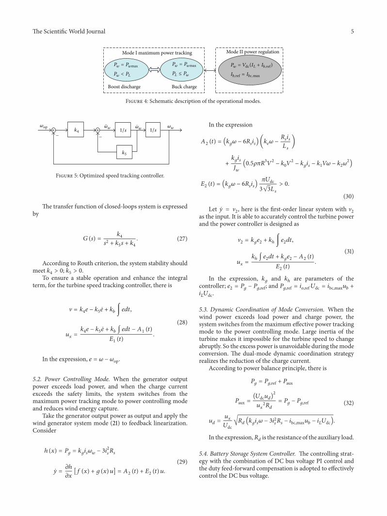

International Journal of
AerospaceEngineeringHindawi Publishing Corporationhttpwwwhindawicom Volume 2014
RoboticsJournal of
Hindawi Publishing Corporationhttpwwwhindawicom Volume 2014
Hindawi Publishing Corporationhttpwwwhindawicom Volume 2014
Active and Passive Electronic Components
Control Scienceand Engineering
Journal of
Hindawi Publishing Corporationhttpwwwhindawicom Volume 2014
International Journal of
RotatingMachinery
Hindawi Publishing Corporationhttpwwwhindawicom Volume 2014
Hindawi Publishing Corporation httpwwwhindawicom
Journal ofEngineeringVolume 2014
Submit your manuscripts athttpwwwhindawicom
VLSI Design
Hindawi Publishing Corporationhttpwwwhindawicom Volume 2014
Hindawi Publishing Corporationhttpwwwhindawicom Volume 2014
Shock and Vibration
Hindawi Publishing Corporationhttpwwwhindawicom Volume 2014
Civil EngineeringAdvances in
Acoustics and VibrationAdvances in
Hindawi Publishing Corporationhttpwwwhindawicom Volume 2014
Hindawi Publishing Corporationhttpwwwhindawicom Volume 2014
Electrical and Computer Engineering
Journal of
Advances inOptoElectronics
Hindawi Publishing Corporation httpwwwhindawicom
Volume 2014
The Scientific World JournalHindawi Publishing Corporation httpwwwhindawicom Volume 2014
SensorsJournal of
Hindawi Publishing Corporationhttpwwwhindawicom Volume 2014
Modelling amp Simulation in EngineeringHindawi Publishing Corporation httpwwwhindawicom Volume 2014
Hindawi Publishing Corporationhttpwwwhindawicom Volume 2014
Chemical EngineeringInternational Journal of Antennas and
Propagation
International Journal of
Hindawi Publishing Corporationhttpwwwhindawicom Volume 2014
Hindawi Publishing Corporationhttpwwwhindawicom Volume 2014
Navigation and Observation
International Journal of
Hindawi Publishing Corporationhttpwwwhindawicom Volume 2014
DistributedSensor Networks
International Journal of