research article stability assessment and...
TRANSCRIPT
Research ArticleStability Assessment and Optimization Design ofLakeside Open-Pit Slope considering Fluid-Solid Coupling Effect
Wenchen Fan, Ping Cao, Ke Zhang, Kaihui Li, and Chong Chen
School of Resources and Safety Engineering, Central South University, Changsha, Hunan 410083, China
Correspondence should be addressed to Wenchen Fan; fwch [email protected]
Received 29 May 2015; Revised 14 August 2015; Accepted 18 August 2015
Academic Editor: Renata Archetti
Copyright © 2015 Wenchen Fan et al. This is an open access article distributed under the Creative Commons Attribution License,which permits unrestricted use, distribution, and reproduction in any medium, provided the original work is properly cited.
Chengmenshan copper mine, located at Jiujiang city in the Jiangxi Province, is a rarely lakeside open-pit mine in China. Since theopen-pit is very close to Sai Lake, the seasonally changed water level and the distance between lake and slope have great influenceto the stability of open-pit slope. Based on the drill data and geological sections, a numerical model of the slope is built. With thefluid-mechanical interaction associated, the stability of the slopes is numerically analyzed, in which different lake water levels andlake-slope distances are taken into consideration. The comparative analysis shows that a larger lake-slope distance can promisebetter slope stability and weaken the sensitivity of slope stability to water. The stability of slopes with different heights is analyzedto find that the stability weakens and the sensitivity is enhanced with the height increasing. To the most serious situation, the slopeheight and the lake water level being 238m and 17.2m, respectively, the 𝐹
𝑠value equals 1.18945 which is extremely closed to the
allowable safety factor of 1.20 for slope design. According to the minimum 𝐹𝑠for slope design, the minimum distance between lake
and open-pit slope is found to be 60m.
1. Introduction
According to a large number of engineering practices, land-slides of natural and artificial slopes often happen after theheavy rain or continuous rainfall. The failure of reservoirbank slopes occurs in sharp decline of water level, long-termimmersion, and hydrological cycle. It shows that the seepageof ground water in the slope makes great difference to thestability of slope.
Theoretical study and practical experience show thatopen-pit slopes usually experience four stages from excava-tion completion to collapse: the elastic stage, the nonlineardeformation stage, creep deformation stage, and the collapsestage. According to the Mohr-Coulomb criteria, the shearstrength of rock decreases greatly when encountering withwater. To rock slopes, this means a great reduction of stability.With the development of the numerical calculation, manymodules in kinds of numerical software have been devel-oped to realize the hydromechanical coupling in fracturedrock mass [1–4]. The Itasca software FLAC3D based on fastLagrangian method can be used to simulate the flow of fluid
through a permeable solid [5], and the pore pressure of thefluid will change in response to the change of mechanicalvolume.
A lot of studies have been done to learn the couplingmechanism of water pressure and rock mass stress [6–12]. Rutqvist and Stephansson [13] and Wang [14] recog-nized two types of hydromechanical coupling: direct andindirect. Direct coupling occurs through deformation andpore fluid interactions. Indirect coupling is where changesin the mechanical or hydraulic processes affect each otherthrough changes inmechanical and hydraulic properties.Thedeformation of pit slope, which is largely inelastic with creepand slip on structures, causes irreversible changes in the rockmass and hydraulic properties of the mass and is largelyindirect coupling.
The stability of mine slopes depends on the designs.Implicitness or explicitness in this design process is an accep-tance of some instability or a certain percentage of failure[15, 16]. Usually the deformations after excavation and criticalfactors that may cause landslides are taken into considerationin the mine slope design process. A lot of preanalyses are
Hindawi Publishing CorporationMathematical Problems in EngineeringVolume 2015, Article ID 691826, 11 pageshttp://dx.doi.org/10.1155/2015/691826
2 Mathematical Problems in Engineering
made to make sure that the mine slope attains a certainsafety coefficient. In some sense, the slope we designed isan acceptance of some instability or a certain percentageof failure [17]. In fact, the groundwater seepage has seriousinfluence on the stability of mine slope. The deformationof slope rock mass will result in the change of cracks andporosity and then the change of seepage effect. Sartori et al.[18] described that the Randa landslidewas a devastating rocklandslide alongwith high pressure infiltrationwater injection.Cappa et al. [19] found that the infiltration of seasonal rainfallaccelerated the process of Clapiere landslide.
Many methods have been carried out to study the influ-ence of seepage on slope stability. Saada et al. [20] adoptedthe limit analysis method to evaluate the slope stability underseepage. Lv et al. [21] established the mathematical modelof rock mass damage under the influence of seepage. Themathematical model was used to analyze the stability ofcoal mining open-pit slope, and the result indicated thatthe reduction of effective stress caused the failure of theslope. Chu-Agor et al. [22] performed a series of experimentsof the slope instability under the action of water pressure,and the results were applied to the mountain slope stabilityanalysis. Srivastava et al. [23] adopted FLAC5.0 to analyze theinfluence of groundwater seepage on the stability of slopeswith different slope conditions and material properties.
Numerical modeling is an efficientmethod in the analysisof slope stability under the action of seepage. The Itascasoftware FLAC3D has been widely used in the analysis ofunderground tunnels, open-pit mining, and undergroundmining complicating gravity, groundwater, and other factors.But there are some difficulties in the construction of a com-plex numerical model by employing FLAC3D alone. Someresearchers constructed the model by the way of integratingSURPAC and FLAC3D [24–28]. In this study, DIMINE, a3D geological model construction software, is adopted toconstruct the geologic model of a lakeside open-pit coppermine. Then the model is imported into FLAC3D with theassistance ofMidas-GTS.Theopen-pit slope stability is finallyassessed numerically by FLAC3D associated with the lakewater. Comparing the safety factors of slope under differentheights of water level, a reasonable distance between lake andopen-pit slope is determined.
2. Engineering Background
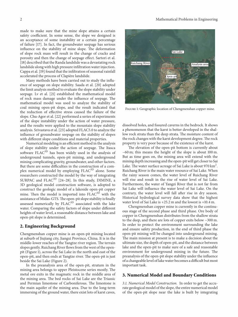
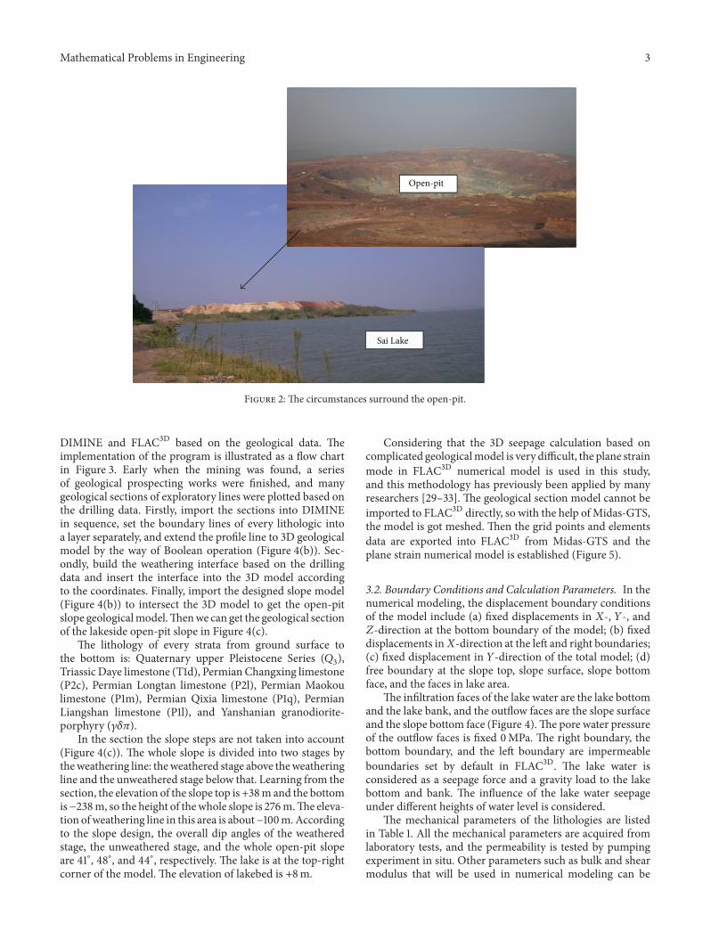
Chengmenshan copper mine is an open-pit mining locatedat suburb of Jiujiang city, Jiangxi Province, China. It is in themiddle-lower reaches of the Yangtze river region.The terrainslopes gently. RuichangRiver flows from thewest of the open-pit (Figure 1), across the Sai Lake in the north and east of theopen-pit, and then ends at Yangtze river. The open-pit is justbeside the Sai Lake (Figure 2).
In the preanalysis area of the open-pit, stratum in themining area belongs to upper Pleistocene series mostly. Themetal ore exits in the magmatic rock in the middle area ofthe mining area. The bed rocks of Sai Lake are the Triassicand Permian limestone of Carboniferous. The limestone isthe main aquifer of the mining area. Due to the long-termimmersing of the ground water, there exist lots of karst caves,
Sai Lake
Ruichang River Analysis area
Open-pit
Figure 1: Geographic location of Chengmenshan copper mine.
dissolved holes, and fissured caverns in the bedrock. It showsa phenomenon that the karst is better developed in the shal-low rock strata than the deep strata. The moisture content ofthe rock changes with the karst development degree.The rockproperty is very poor because of the existence of the karst.
The elevation of the open-pit bottom is currently about−60m; this means the height of the slope is about 100m.But as time goes on, the mining area will extend with themining depth increasing and the open-pit will get closer to SaiLake. The water surface acreage of Sai Lake is about 970 km2.Ruichang River is the main water resource of Sai Lake. Whenthe rainy season comes, the water level of Ruichang Riverwill rise and result in the rise of water level of Sai Lake.Furthermore, the water of Yangzi River that is not far fromSai Lake will influence the water level of Sai Lake. On thecontrary, the water level will fall after rise in dry season.Historical hydrological survey data show that the highestwater level of Sai Lake is +25.2m and the lowest is +10.4m.
Chengmenshan copper mine is currently in the continu-ous stage of the second phase and third phase. Ore body ofcopper in Chengmenshan distributes from the shallow stratato the deep, and there are lots of copper exits below −300m.In order to protect the environment surrounding the lakeand ensure safety production, in the end of third phase theopen-pit mining will be changed into underground mining.The main mission at present is to make a decision about theultimate size, the depth of open-pit, and the distance betweenlake and the open-pit to make sure of a safe and reasonableenvironment for underground mining in the future. Thepreanalysis of the open-pit slope stability under the influenceof a changeable level of lakewater becomes a difficult butmostimportant task.
3. Numerical Model and Boundary Conditions
3.1. Numerical Model Construction. In order to get the accu-rate geologicalmodel of the slope, the entire numericalmodelof the open-pit slope near the lake is built by integrating
Mathematical Problems in Engineering 3
Open-pit
Sai Lake
Figure 2: The circumstances surround the open-pit.
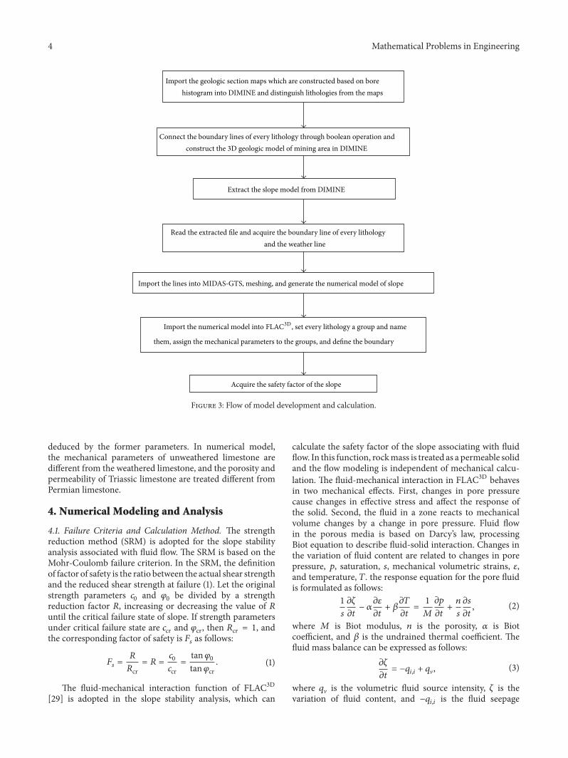
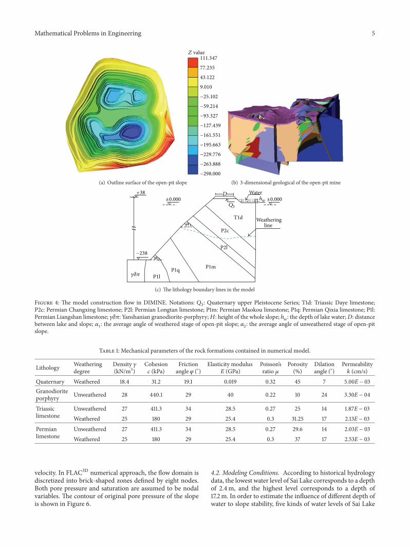
DIMINE and FLAC3D based on the geological data. Theimplementation of the program is illustrated as a flow chartin Figure 3. Early when the mining was found, a seriesof geological prospecting works were finished, and manygeological sections of exploratory lines were plotted based onthe drilling data. Firstly, import the sections into DIMINEin sequence, set the boundary lines of every lithologic intoa layer separately, and extend the profile line to 3D geologicalmodel by the way of Boolean operation (Figure 4(b)). Sec-ondly, build the weathering interface based on the drillingdata and insert the interface into the 3D model accordingto the coordinates. Finally, import the designed slope model(Figure 4(b)) to intersect the 3D model to get the open-pitslope geologicalmodel.Thenwe can get the geological sectionof the lakeside open-pit slope in Figure 4(c).
The lithology of every strata from ground surface tothe bottom is: Quaternary upper Pleistocene Series (𝑄
3),
Triassic Daye limestone (T1d), Permian Changxing limestone(P2c), Permian Longtan limestone (P2l), Permian Maokoulimestone (P1m), Permian Qixia limestone (P1q), PermianLiangshan limestone (P1l), and Yanshanian granodiorite-porphyry (𝛾𝛿𝜋).
In the section the slope steps are not taken into account(Figure 4(c)). The whole slope is divided into two stages bytheweathering line: theweathered stage above theweatheringline and the unweathered stage below that. Learning from thesection, the elevation of the slope top is +38m and the bottomis−238m, so the height of thewhole slope is 276m.The eleva-tion ofweathering line in this area is about−100m.Accordingto the slope design, the overall dip angles of the weatheredstage, the unweathered stage, and the whole open-pit slopeare 41∘, 48∘, and 44∘, respectively. The lake is at the top-rightcorner of the model. The elevation of lakebed is +8m.
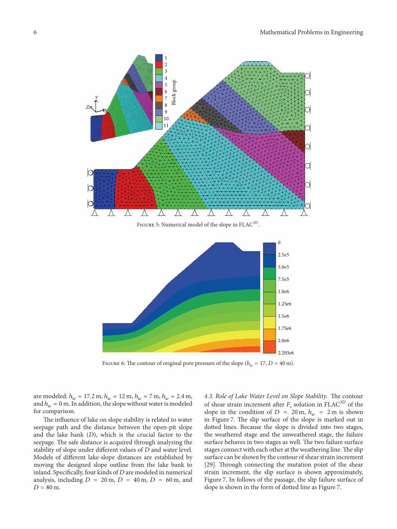
Considering that the 3D seepage calculation based oncomplicated geologicalmodel is very difficult, the plane strainmode in FLAC3D numerical model is used in this study,and this methodology has previously been applied by manyresearchers [29–33]. The geological section model cannot beimported to FLAC3D directly, so with the help ofMidas-GTS,the model is got meshed. Then the grid points and elementsdata are exported into FLAC3D from Midas-GTS and theplane strain numerical model is established (Figure 5).
3.2. Boundary Conditions and Calculation Parameters. In thenumerical modeling, the displacement boundary conditionsof the model include (a) fixed displacements in 𝑋-, 𝑌-, and𝑍-direction at the bottom boundary of the model; (b) fixeddisplacements in𝑋-direction at the left and right boundaries;(c) fixed displacement in 𝑌-direction of the total model; (d)free boundary at the slope top, slope surface, slope bottomface, and the faces in lake area.
The infiltration faces of the lake water are the lake bottomand the lake bank, and the outflow faces are the slope surfaceand the slope bottom face (Figure 4).The pore water pressureof the outflow faces is fixed 0MPa. The right boundary, thebottom boundary, and the left boundary are impermeableboundaries set by default in FLAC3D. The lake water isconsidered as a seepage force and a gravity load to the lakebottom and bank. The influence of the lake water seepageunder different heights of water level is considered.
The mechanical parameters of the lithologies are listedin Table 1. All the mechanical parameters are acquired fromlaboratory tests, and the permeability is tested by pumpingexperiment in situ. Other parameters such as bulk and shearmodulus that will be used in numerical modeling can be
4 Mathematical Problems in Engineering
Connect the boundary lines of every lithology through boolean operation andconstruct the 3D geologic model of mining area in DIMINE
Extract the slope model from DIMINE
Acquire the safety factor of the slope
Import the lines into MIDAS-GTS, meshing, and generate the numerical model of slope
them, assign the mechanical parameters to the groups, and define the boundary
Read the extracted file and acquire the boundary line of every lithology and the weather line
Import the geologic section maps which are constructed based on borehistogram into DIMINE and distinguish lithologies from the maps
Import the numerical model into FLAC3D, set every lithology a group and name
Figure 3: Flow of model development and calculation.
deduced by the former parameters. In numerical model,the mechanical parameters of unweathered limestone aredifferent from the weathered limestone, and the porosity andpermeability of Triassic limestone are treated different fromPermian limestone.
4. Numerical Modeling and Analysis
4.1. Failure Criteria and Calculation Method. The strengthreduction method (SRM) is adopted for the slope stabilityanalysis associated with fluid flow. The SRM is based on theMohr-Coulomb failure criterion. In the SRM, the definitionof factor of safety is the ratio between the actual shear strengthand the reduced shear strength at failure (1). Let the originalstrength parameters 𝑐
0and 𝜑
0be divided by a strength
reduction factor 𝑅, increasing or decreasing the value of 𝑅until the critical failure state of slope. If strength parametersunder critical failure state are 𝑐cr and 𝜑cr, then 𝑅cr = 1, andthe corresponding factor of safety is 𝐹
𝑠as follows:
𝐹𝑠=𝑅
𝑅cr= 𝑅 =
𝑐0
𝑐cr=
tan𝜑0
tan𝜑cr. (1)
The fluid-mechanical interaction function of FLAC3D[29] is adopted in the slope stability analysis, which can
calculate the safety factor of the slope associating with fluidflow. In this function, rockmass is treated as a permeable solidand the flow modeling is independent of mechanical calcu-lation. The fluid-mechanical interaction in FLAC3D behavesin two mechanical effects. First, changes in pore pressurecause changes in effective stress and affect the response ofthe solid. Second, the fluid in a zone reacts to mechanicalvolume changes by a change in pore pressure. Fluid flowin the porous media is based on Darcy’s law, processingBiot equation to describe fluid-solid interaction. Changes inthe variation of fluid content are related to changes in porepressure, 𝑝, saturation, 𝑠, mechanical volumetric strains, 𝜀,and temperature, 𝑇. the response equation for the pore fluidis formulated as follows:
1
𝑠
𝜕𝜁
𝜕𝑡− 𝛼𝜕𝜀
𝜕𝑡+ 𝛽𝜕𝑇
𝜕𝑡=1
𝑀
𝜕𝑝
𝜕𝑡+𝑛
𝑠
𝜕𝑠
𝜕𝑡, (2)
where 𝑀 is Biot modulus, 𝑛 is the porosity, 𝛼 is Biotcoefficient, and 𝛽 is the undrained thermal coefficient. Thefluid mass balance can be expressed as follows:
𝜕𝜁
𝜕𝑡= −𝑞𝑖,𝑖+ 𝑞V, (3)
where 𝑞V is the volumetric fluid source intensity, 𝜁 is thevariation of fluid content, and −𝑞
𝑖,𝑖is the fluid seepage
Mathematical Problems in Engineering 5
111.347
77.235
43.122
9.010
−25.102
−59.214
−93.327
−127.439
−161.551
−195.663
−229.776
−263.888
−298.000
Z value
(a) Outline surface of the open-pit slope (b) 3-dimensional geological of the open-pit mine
Weathering
Water
H
line
+38
±0.000±0.000
−238
P1l
P2l
P1q P1m
P2c
T1d
Q3
D
𝛾𝛿𝜋
𝛼1
𝛼2
hw
(c) The lithology boundary lines in the model
Figure 4: The model construction flow in DIMINE. Notations: 𝑄3: Quaternary upper Pleistocene Series; T1d: Triassic Daye limestone;
P2c: Permian Changxing limestone; P2l: Permian Longtan limestone; P1m: Permian Maokou limestone; P1q: Permian Qixia limestone; P1l:Permian Liangshan limestone; 𝛾𝛿𝜋: Yanshanian granodiorite-porphyry;𝐻: height of the whole slope; ℎ
𝑤: the depth of lake water;𝐷: distance
between lake and slope; 𝛼1: the average angle of weathered stage of open-pit slope; 𝛼
2: the average angle of unweathered stage of open-pit
slope.
Table 1: Mechanical parameters of the rock formations contained in numerical model.
Lithology Weatheringdegree
Density 𝛾(kN/m3)
Cohesion𝑐 (kPa)
Frictionangle 𝜑 (∘)
Elasticity modulus𝐸 (GPa)
Poisson’sratio 𝜇
Porosity(%)
Dilationangle (∘)
Permeability𝑘 (cm/s)
Quaternary Weathered 18.4 31.2 19.1 0.019 0.32 45 7 5.00E − 03Granodioriteporphyry Unweathered 28 440.1 29 40 0.22 10 24 3.30E − 04
Triassiclimestone
Unweathered 27 411.3 34 28.5 0.27 25 14 1.87E − 03Weathered 25 180 29 25.4 0.3 31.25 17 2.13E − 03
Permianlimestone
Unweathered 27 411.3 34 28.5 0.27 29.6 14 2.03E − 03Weathered 25 180 29 25.4 0.3 37 17 2.53E − 03
velocity. In FLAC3D numerical approach, the flow domain isdiscretized into brick-shaped zones defined by eight nodes.Both pore pressure and saturation are assumed to be nodalvariables. The contour of original pore pressure of the slopeis shown in Figure 6.
4.2. Modeling Conditions. According to historical hydrologydata, the lowest water level of Sai Lake corresponds to a depthof 2.4m, and the highest level corresponds to a depth of17.2m. In order to estimate the influence of different depth ofwater to slope stability, five kinds of water levels of Sai Lake
6 Mathematical Problems in Engineering
Y
Z
Y
Bloc
k gr
oup
1
2
3
4
5
6
7
8
9
10
11
X
Figure 5: Numerical model of the slope in FLAC3D.
2.5e5
5.0e5
7.5e5
1.0e6
1.25e6
2.203e6
1.75e6
1.5e6
2.0e6
0
Figure 6: The contour of original pore pressure of the slope (ℎ𝑤= 17,𝐷 = 40m).
are modeled: ℎ𝑤= 17.2m, ℎ
𝑤= 12m, ℎ
𝑤= 7m, ℎ
𝑤= 2.4m,
and ℎ𝑤= 0m. In addition, the slopewithoutwater ismodeled
for comparison.The influence of lake on slope stability is related to water
seepage path and the distance between the open-pit slopeand the lake bank (𝐷), which is the crucial factor to theseepage. The safe distance is acquired through analyzing thestability of slope under different values of 𝐷 and water level.Models of different lake-slope distances are established bymoving the designed slope outline from the lake bank toinland. Specifically, four kinds of𝐷 aremodeled in numericalanalysis, including 𝐷 = 20m, 𝐷 = 40m, 𝐷 = 60m, and𝐷 = 80m.
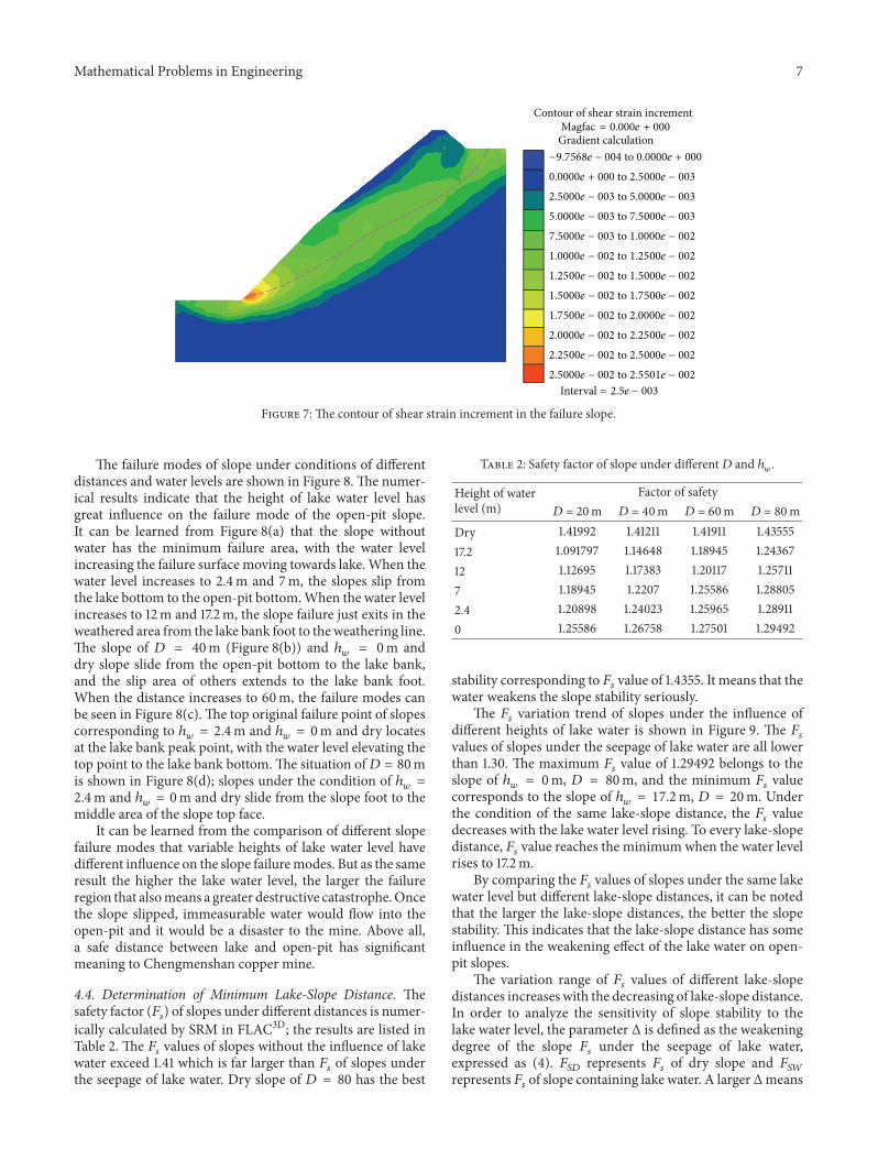
4.3. Role of Lake Water Level on Slope Stability. The contourof shear strain increment after 𝐹
𝑠solution in FLAC3D of the
slope in the condition of 𝐷 = 20m, ℎ𝑤= 2m is shown
in Figure 7. The slip surface of the slope is marked out indotted lines. Because the slope is divided into two stages,the weathered stage and the unweathered stage, the failuresurface behaves in two stages as well. The two failure surfacestages connect with each other at the weathering line.The slipsurface can be shown by the contour of shear strain increment[29]. Through connecting the mutation point of the shearstrain increment, the slip surface is shown approximately,Figure 7. In follows of the passage, the slip failure surface ofslope is shown in the form of dotted line as Figure 7.
Mathematical Problems in Engineering 7
Contour of shear strain incrementMagfac = 0.000e + 000
Gradient calculation−9.7568e − 004 to 0.0000e + 000
0.0000e + 000 to 2.5000e − 003
2.5000e − 003 to 5.0000e − 003
5.0000e − 003 to 7.5000e − 003
7.5000e − 003 to 1.0000e − 002
1.0000e − 002 to 1.2500e − 002
1.2500e − 002 to 1.5000e − 002
1.5000e − 002 to 1.7500e − 002
1.7500e − 002 to 2.0000e − 002
2.0000e − 002 to 2.2500e − 002
2.2500e − 002 to 2.5000e − 002
2.5000e − 002 to 2.5501e − 002
Interval = 2.5e − 003
Figure 7: The contour of shear strain increment in the failure slope.
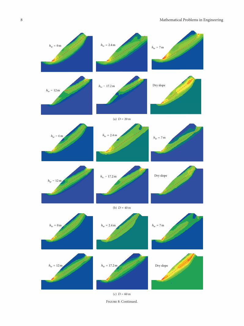
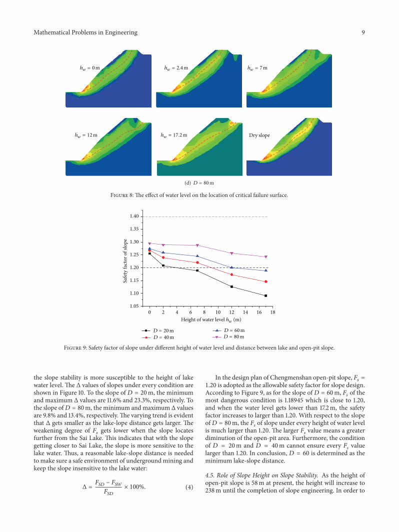
The failure modes of slope under conditions of differentdistances and water levels are shown in Figure 8. The numer-ical results indicate that the height of lake water level hasgreat influence on the failure mode of the open-pit slope.It can be learned from Figure 8(a) that the slope withoutwater has the minimum failure area, with the water levelincreasing the failure surface moving towards lake.When thewater level increases to 2.4m and 7m, the slopes slip fromthe lake bottom to the open-pit bottom.When the water levelincreases to 12m and 17.2m, the slope failure just exits in theweathered area from the lake bank foot to theweathering line.The slope of 𝐷 = 40m (Figure 8(b)) and ℎ
𝑤= 0m and
dry slope slide from the open-pit bottom to the lake bank,and the slip area of others extends to the lake bank foot.When the distance increases to 60m, the failure modes canbe seen in Figure 8(c). The top original failure point of slopescorresponding to ℎ
𝑤= 2.4m and ℎ
𝑤= 0m and dry locates
at the lake bank peak point, with the water level elevating thetop point to the lake bank bottom.The situation of𝐷 = 80mis shown in Figure 8(d); slopes under the condition of ℎ
𝑤=
2.4m and ℎ𝑤= 0m and dry slide from the slope foot to the
middle area of the slope top face.It can be learned from the comparison of different slope
failure modes that variable heights of lake water level havedifferent influence on the slope failuremodes. But as the sameresult the higher the lake water level, the larger the failureregion that alsomeans a greater destructive catastrophe.Oncethe slope slipped, immeasurable water would flow into theopen-pit and it would be a disaster to the mine. Above all,a safe distance between lake and open-pit has significantmeaning to Chengmenshan copper mine.
4.4. Determination of Minimum Lake-Slope Distance. Thesafety factor (𝐹
𝑠) of slopes under different distances is numer-
ically calculated by SRM in FLAC3D; the results are listed inTable 2. The 𝐹
𝑠values of slopes without the influence of lake
water exceed 1.41 which is far larger than 𝐹𝑠of slopes under
the seepage of lake water. Dry slope of 𝐷 = 80 has the best
Table 2: Safety factor of slope under different𝐷 and ℎ𝑤.
Height of waterlevel (m)
Factor of safety𝐷 = 20m 𝐷 = 40m 𝐷 = 60m 𝐷 = 80m
Dry 1.41992 1.41211 1.41911 1.4355517.2 1.091797 1.14648 1.18945 1.2436712 1.12695 1.17383 1.20117 1.257117 1.18945 1.2207 1.25586 1.288052.4 1.20898 1.24023 1.25965 1.289110 1.25586 1.26758 1.27501 1.29492
stability corresponding to 𝐹𝑠value of 1.4355. It means that the
water weakens the slope stability seriously.The 𝐹
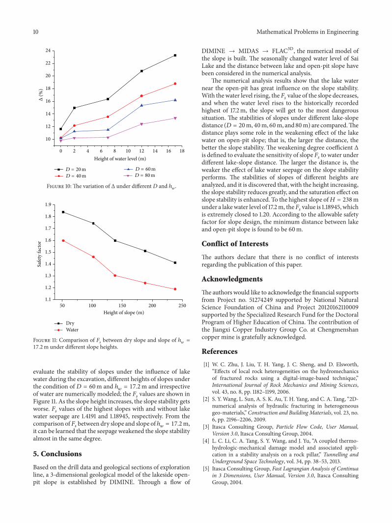
𝑠variation trend of slopes under the influence of
different heights of lake water is shown in Figure 9. The 𝐹𝑠
values of slopes under the seepage of lake water are all lowerthan 1.30. The maximum 𝐹
𝑠value of 1.29492 belongs to the
slope of ℎ𝑤= 0m, 𝐷 = 80m, and the minimum 𝐹
𝑠value
corresponds to the slope of ℎ𝑤= 17.2m, 𝐷 = 20m. Under
the condition of the same lake-slope distance, the 𝐹𝑠value
decreases with the lake water level rising. To every lake-slopedistance, 𝐹
𝑠value reaches the minimum when the water level
rises to 17.2m.By comparing the 𝐹
𝑠values of slopes under the same lake
water level but different lake-slope distances, it can be notedthat the larger the lake-slope distances, the better the slopestability. This indicates that the lake-slope distance has someinfluence in the weakening effect of the lake water on open-pit slopes.
The variation range of 𝐹𝑠values of different lake-slope
distances increases with the decreasing of lake-slope distance.In order to analyze the sensitivity of slope stability to thelake water level, the parameter Δ is defined as the weakeningdegree of the slope 𝐹
𝑠under the seepage of lake water,
expressed as (4). 𝐹𝑆𝐷
represents 𝐹𝑠of dry slope and 𝐹
𝑆𝑊
represents 𝐹𝑠of slope containing lake water. A largerΔmeans
8 Mathematical Problems in Engineering
Dry slope
hw = 0m hw = 2.4m
hw = 12mhw = 17.2m
hw = 7m
hw = 12mhw = 17.2m Dry slope
hw = 7mhw = 2.4mhw = 0m
(a) 𝐷 = 20m
Dry slope
hw = 0m hw = 2.4m
hw = 12mhw = 17.2m
hw = 7m
hw = 12mhw = 17.2m Dry slope
hw = 7mhw = 2.4mhw = 0m
(b) 𝐷 = 40m
Dry slope
hw = 0m hw = 2.4m
hw = 12m hw = 17.2m
hw = 7m
(c) 𝐷 = 60m
Figure 8: Continued.
Mathematical Problems in Engineering 9
Dry slope
hw = 0m hw = 2.4m
hw = 12m hw = 17.2m
hw = 7m
(d) 𝐷 = 80m
Figure 8: The effect of water level on the location of critical failure surface.
0 2 4 6 8 10 12 14 16 181.05
1.10
1.15
1.20
1.25
1.30
1.35
1.40
Saf
ety
fact
or o
f slo
pe
Height of water level hw (m)
D = 80mD = 60m
D = 40mD = 20m
Figure 9: Safety factor of slope under different height of water level and distance between lake and open-pit slope.
the slope stability is more susceptible to the height of lakewater level. The Δ values of slopes under every condition areshown in Figure 10. To the slope of 𝐷 = 20m, the minimumand maximum Δ values are 11.6% and 23.3%, respectively. Tothe slope of𝐷 = 80m, the minimum andmaximum Δ valuesare 9.8% and 13.4%, respectively. The varying trend is evidentthat Δ gets smaller as the lake-lope distance gets larger. Theweakening degree of 𝐹
𝑠gets lower when the slope locates
further from the Sai Lake. This indicates that with the slopegetting closer to Sai Lake, the slope is more sensitive to thelake water. Thus, a reasonable lake-slope distance is neededto make sure a safe environment of undergroundmining andkeep the slope insensitive to the lake water:
Δ =𝐹𝑆𝐷− 𝐹𝑆𝑊
𝐹𝑆𝐷
× 100%. (4)
In the design plan of Chengmenshan open-pit slope, 𝐹𝑠=
1.20 is adopted as the allowable safety factor for slope design.According to Figure 9, as for the slope of𝐷 = 60m, 𝐹
𝑠of the
most dangerous condition is 1.18945 which is close to 1.20,and when the water level gets lower than 17.2m, the safetyfactor increases to larger than 1.20. With respect to the slopeof𝐷 = 80m, the 𝐹
𝑠of slope under every height of water level
is much larger than 1.20. The larger 𝐹𝑠value means a greater
diminution of the open-pit area. Furthermore, the conditionof 𝐷 = 20m and 𝐷 = 40m cannot ensure every 𝐹
𝑠value
larger than 1.20. In conclusion, 𝐷 = 60 is determined as theminimum lake-slope distance.
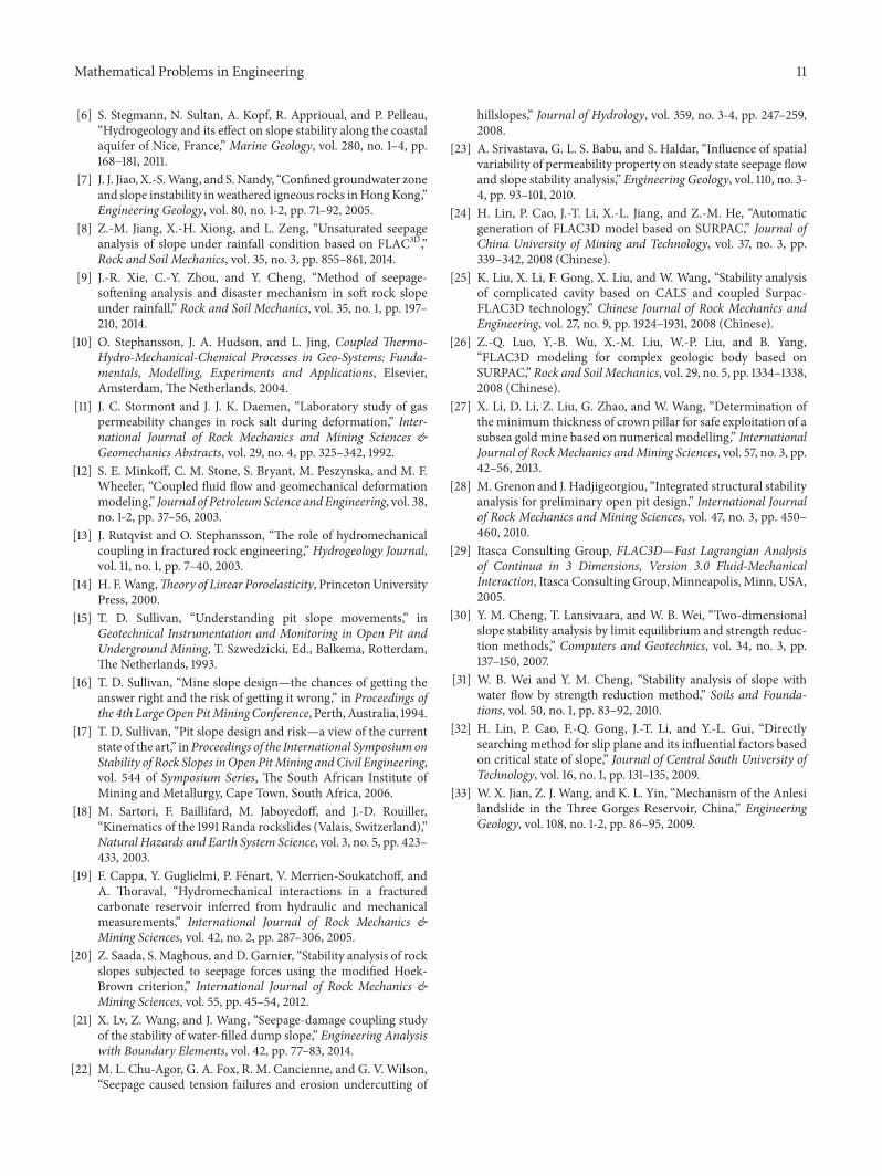
4.5. Role of Slope Height on Slope Stability. As the height ofopen-pit slope is 58m at present, the height will increase to238m until the completion of slope engineering. In order to
10 Mathematical Problems in Engineering
0 2 4 6 8 10 12 14 16 18
10
12
14
16
18
20
22
24
Δ(%
)
D = 80mD = 60m
D = 40mD = 20m
Height of water level (m)
Figure 10: The variation of Δ under different𝐷 and ℎ𝑤.
50 100 150 200 2501.1
1.2
1.3
1.4
1.5
1.6
1.7
1.8
1.9
Safe
ty fa
ctor
Height of slope (m)
DryWater
Figure 11: Comparison of 𝐹𝑠between dry slope and slope of ℎ
𝑤=
17.2m under different slope heights.
evaluate the stability of slopes under the influence of lakewater during the excavation, different heights of slopes underthe condition of 𝐷 = 60m and ℎ
𝑤= 17.2m and irrespective
of water are numerically modeled; the 𝐹𝑠values are shown in
Figure 11. As the slope height increases, the slope stability getsworse. 𝐹
𝑠values of the highest slopes with and without lake
water seepage are 1.4191 and 1.18945, respectively. From thecomparison of𝐹
𝑠between dry slope and slope of ℎ
𝑤= 17.2m,
it can be learned that the seepage weakened the slope stabilityalmost in the same degree.
5. Conclusions
Based on the drill data and geological sections of explorationline, a 3-dimensional geological model of the lakeside open-pit slope is established by DIMINE. Through a flow of
DIMINE → MIDAS → FLAC3D, the numerical model ofthe slope is built. The seasonally changed water level of SaiLake and the distance between lake and open-pit slope havebeen considered in the numerical analysis.
The numerical analysis results show that the lake waternear the open-pit has great influence on the slope stability.With the water level rising, the𝐹
𝑠value of the slope decreases,
and when the water level rises to the historically recordedhighest of 17.2m, the slope will get to the most dangeroussituation. The stabilities of slopes under different lake-slopedistance (𝐷 = 20m, 40m, 60m, and 80m) are compared.Thedistance plays some role in the weakening effect of the lakewater on open-pit slope; that is, the larger the distance, thebetter the slope stability. The weakening degree coefficient Δis defined to evaluate the sensitivity of slope𝐹
𝑠to water under
different lake-slope distance. The larger the distance is, theweaker the effect of lake water seepage on the slope stabilityperforms. The stabilities of slopes of different heights areanalyzed, and it is discovered that, with the height increasing,the slope stability reduces greatly, and the saturation effect onslope stability is enhanced. To the highest slope of𝐻 = 238munder a lakewater level of 17.2m, the𝐹
𝑠value is 1.18945, which
is extremely closed to 1.20. According to the allowable safetyfactor for slope design, the minimum distance between lakeand open-pit slope is found to be 60m.
Conflict of Interests
The authors declare that there is no conflict of interestsregarding the publication of this paper.
Acknowledgments
The authors would like to acknowledge the financial supportsfrom Project no. 51274249 supported by National NaturalScience Foundation of China and Project 20120162110009supported by the Specialized Research Fund for the DoctoralProgram of Higher Education of China. The contribution ofthe Jiangxi Copper Industry Group Co. at Chengmenshancopper mine is gratefully acknowledged.
References
[1] W. C. Zhu, J. Liu, T. H. Yang, J. C. Sheng, and D. Elsworth,“Effects of local rock heterogeneities on the hydromechanicsof fractured rocks using a digital-image-based technique,”International Journal of Rock Mechanics and Mining Sciences,vol. 43, no. 8, pp. 1182–1199, 2006.
[2] S. Y.Wang, L. Sun, A. S. K. Au, T. H. Yang, and C. A. Tang, “2D-numerical analysis of hydraulic fracturing in heterogeneousgeo-materials,” Construction and Building Materials, vol. 23, no.6, pp. 2196–2206, 2009.
[3] Itasca Consulting Group, Particle Flow Code, User Manual,Version 3.0, Itasca Consulting Group, 2004.
[4] L. C. Li, C. A. Tang, S. Y. Wang, and J. Yu, “A coupled thermo-hydrologic-mechanical damage model and associated appli-cation in a stability analysis on a rock pillar,” Tunnelling andUnderground Space Technology, vol. 34, pp. 38–53, 2013.
[5] Itasca Consulting Group, Fast Lagrangian Analysis of Continuain 3 Dimensions, User Manual, Version 3.0, Itasca ConsultingGroup, 2004.
Mathematical Problems in Engineering 11
[6] S. Stegmann, N. Sultan, A. Kopf, R. Apprioual, and P. Pelleau,“Hydrogeology and its effect on slope stability along the coastalaquifer of Nice, France,” Marine Geology, vol. 280, no. 1–4, pp.168–181, 2011.
[7] J. J. Jiao, X.-S.Wang, and S.Nandy, “Confined groundwater zoneand slope instability in weathered igneous rocks inHongKong,”Engineering Geology, vol. 80, no. 1-2, pp. 71–92, 2005.
[8] Z.-M. Jiang, X.-H. Xiong, and L. Zeng, “Unsaturated seepageanalysis of slope under rainfall condition based on FLAC3D,”Rock and Soil Mechanics, vol. 35, no. 3, pp. 855–861, 2014.
[9] J.-R. Xie, C.-Y. Zhou, and Y. Cheng, “Method of seepage-softening analysis and disaster mechanism in soft rock slopeunder rainfall,” Rock and Soil Mechanics, vol. 35, no. 1, pp. 197–210, 2014.
[10] O. Stephansson, J. A. Hudson, and L. Jing, Coupled Thermo-Hydro-Mechanical-Chemical Processes in Geo-Systems: Funda-mentals, Modelling, Experiments and Applications, Elsevier,Amsterdam, The Netherlands, 2004.
[11] J. C. Stormont and J. J. K. Daemen, “Laboratory study of gaspermeability changes in rock salt during deformation,” Inter-national Journal of Rock Mechanics and Mining Sciences &Geomechanics Abstracts, vol. 29, no. 4, pp. 325–342, 1992.
[12] S. E. Minkoff, C. M. Stone, S. Bryant, M. Peszynska, and M. F.Wheeler, “Coupled fluid flow and geomechanical deformationmodeling,” Journal of PetroleumScience andEngineering, vol. 38,no. 1-2, pp. 37–56, 2003.
[13] J. Rutqvist and O. Stephansson, “The role of hydromechanicalcoupling in fractured rock engineering,” Hydrogeology Journal,vol. 11, no. 1, pp. 7–40, 2003.
[14] H. F.Wang,Theory of Linear Poroelasticity, PrincetonUniversityPress, 2000.
[15] T. D. Sullivan, “Understanding pit slope movements,” inGeotechnical Instrumentation and Monitoring in Open Pit andUnderground Mining, T. Szwedzicki, Ed., Balkema, Rotterdam,The Netherlands, 1993.
[16] T. D. Sullivan, “Mine slope design—the chances of getting theanswer right and the risk of getting it wrong,” in Proceedings ofthe 4th LargeOpenPitMiningConference, Perth,Australia, 1994.
[17] T. D. Sullivan, “Pit slope design and risk—a view of the currentstate of the art,” inProceedings of the International SymposiumonStability of Rock Slopes inOpen PitMining andCivil Engineering,vol. 544 of Symposium Series, The South African Institute ofMining and Metallurgy, Cape Town, South Africa, 2006.
[18] M. Sartori, F. Baillifard, M. Jaboyedoff, and J.-D. Rouiller,“Kinematics of the 1991 Randa rockslides (Valais, Switzerland),”Natural Hazards and Earth System Science, vol. 3, no. 5, pp. 423–433, 2003.
[19] F. Cappa, Y. Guglielmi, P. Fenart, V. Merrien-Soukatchoff, andA. Thoraval, “Hydromechanical interactions in a fracturedcarbonate reservoir inferred from hydraulic and mechanicalmeasurements,” International Journal of Rock Mechanics &Mining Sciences, vol. 42, no. 2, pp. 287–306, 2005.
[20] Z. Saada, S. Maghous, and D. Garnier, “Stability analysis of rockslopes subjected to seepage forces using the modified Hoek-Brown criterion,” International Journal of Rock Mechanics &Mining Sciences, vol. 55, pp. 45–54, 2012.
[21] X. Lv, Z. Wang, and J. Wang, “Seepage-damage coupling studyof the stability of water-filled dump slope,” Engineering Analysiswith Boundary Elements, vol. 42, pp. 77–83, 2014.
[22] M. L. Chu-Agor, G. A. Fox, R. M. Cancienne, and G. V. Wilson,“Seepage caused tension failures and erosion undercutting of
hillslopes,” Journal of Hydrology, vol. 359, no. 3-4, pp. 247–259,2008.
[23] A. Srivastava, G. L. S. Babu, and S. Haldar, “Influence of spatialvariability of permeability property on steady state seepage flowand slope stability analysis,” Engineering Geology, vol. 110, no. 3-4, pp. 93–101, 2010.
[24] H. Lin, P. Cao, J.-T. Li, X.-L. Jiang, and Z.-M. He, “Automaticgeneration of FLAC3D model based on SURPAC,” Journal ofChina University of Mining and Technology, vol. 37, no. 3, pp.339–342, 2008 (Chinese).
[25] K. Liu, X. Li, F. Gong, X. Liu, and W. Wang, “Stability analysisof complicated cavity based on CALS and coupled Surpac-FLAC3D technology,” Chinese Journal of Rock Mechanics andEngineering, vol. 27, no. 9, pp. 1924–1931, 2008 (Chinese).
[26] Z.-Q. Luo, Y.-B. Wu, X.-M. Liu, W.-P. Liu, and B. Yang,“FLAC3D modeling for complex geologic body based onSURPAC,”Rock and Soil Mechanics, vol. 29, no. 5, pp. 1334–1338,2008 (Chinese).
[27] X. Li, D. Li, Z. Liu, G. Zhao, and W. Wang, “Determination oftheminimum thickness of crown pillar for safe exploitation of asubsea gold mine based on numerical modelling,” InternationalJournal of RockMechanics andMining Sciences, vol. 57, no. 3, pp.42–56, 2013.
[28] M. Grenon and J. Hadjigeorgiou, “Integrated structural stabilityanalysis for preliminary open pit design,” International Journalof Rock Mechanics and Mining Sciences, vol. 47, no. 3, pp. 450–460, 2010.
[29] Itasca Consulting Group, FLAC3D—Fast Lagrangian Analysisof Continua in 3 Dimensions, Version 3.0 Fluid-MechanicalInteraction, Itasca Consulting Group,Minneapolis, Minn, USA,2005.
[30] Y. M. Cheng, T. Lansivaara, and W. B. Wei, “Two-dimensionalslope stability analysis by limit equilibrium and strength reduc-tion methods,” Computers and Geotechnics, vol. 34, no. 3, pp.137–150, 2007.
[31] W. B. Wei and Y. M. Cheng, “Stability analysis of slope withwater flow by strength reduction method,” Soils and Founda-tions, vol. 50, no. 1, pp. 83–92, 2010.
[32] H. Lin, P. Cao, F.-Q. Gong, J.-T. Li, and Y.-L. Gui, “Directlysearching method for slip plane and its influential factors basedon critical state of slope,” Journal of Central South University ofTechnology, vol. 16, no. 1, pp. 131–135, 2009.
[33] W. X. Jian, Z. J. Wang, and K. L. Yin, “Mechanism of the Anlesilandslide in the Three Gorges Reservoir, China,” EngineeringGeology, vol. 108, no. 1-2, pp. 86–95, 2009.

Submit your manuscripts athttp://www.hindawi.com
Hindawi Publishing Corporationhttp://www.hindawi.com Volume 2014
MathematicsJournal of
Hindawi Publishing Corporationhttp://www.hindawi.com Volume 2014
Mathematical Problems in Engineering
Hindawi Publishing Corporationhttp://www.hindawi.com
Differential EquationsInternational Journal of
Volume 2014
Applied MathematicsJournal of
Hindawi Publishing Corporationhttp://www.hindawi.com Volume 2014
Probability and StatisticsHindawi Publishing Corporationhttp://www.hindawi.com Volume 2014
Journal of
Hindawi Publishing Corporationhttp://www.hindawi.com Volume 2014
Mathematical PhysicsAdvances in
Complex AnalysisJournal of
Hindawi Publishing Corporationhttp://www.hindawi.com Volume 2014
OptimizationJournal of
Hindawi Publishing Corporationhttp://www.hindawi.com Volume 2014
CombinatoricsHindawi Publishing Corporationhttp://www.hindawi.com Volume 2014
International Journal of
Hindawi Publishing Corporationhttp://www.hindawi.com Volume 2014
Operations ResearchAdvances in
Journal of
Hindawi Publishing Corporationhttp://www.hindawi.com Volume 2014
Function Spaces
Abstract and Applied AnalysisHindawi Publishing Corporationhttp://www.hindawi.com Volume 2014
International Journal of Mathematics and Mathematical Sciences
Hindawi Publishing Corporationhttp://www.hindawi.com Volume 2014
The Scientific World JournalHindawi Publishing Corporation http://www.hindawi.com Volume 2014
Hindawi Publishing Corporationhttp://www.hindawi.com Volume 2014
Algebra
Discrete Dynamics in Nature and Society
Hindawi Publishing Corporationhttp://www.hindawi.com Volume 2014
Hindawi Publishing Corporationhttp://www.hindawi.com Volume 2014
Decision SciencesAdvances in
Discrete MathematicsJournal of
Hindawi Publishing Corporationhttp://www.hindawi.com
Volume 2014 Hindawi Publishing Corporationhttp://www.hindawi.com Volume 2014
Stochastic AnalysisInternational Journal of