research articles chemie
TRANSCRIPT

Batteries Very Important Paper
Hydrophobic Organic-Electrolyte-Protected Zinc Anodes for AqueousZinc BatteriesLongsheng Cao+, Dan Li+, Tao Deng, Qin Li, and Chunsheng Wang*
Abstract: Aqueous Zn batteries are promising energy-storagedevices. However, their lifespan is limited by irreversible Znanodes owing to water decomposition and Zn dendrite growth.Here, we separate aqueous electrolyte from Zn anode bycoating a thin MOF layer on anode and filling the pores ofMOF with hydrophobic Zn(TFSI)2-tris(2,2,2-trifluoroethyl)-phosphate (TFEP) organic electrolyte that is immiscible withaqueous Zn(TFSI)2–H2O bulk electrolyte. The MOF encapsu-lated Zn(TFSI)2-TFEP forms a ZnF2-Zn3(PO4)2 solid electro-lyte interphase (SEI) preventing Zn dendrite and waterdecomposition. The Zn(TFSI)2-TFEP@MOF electrolyte pro-tected Zn anode enables a Zn j jTi cell to achieve a highaverage Coulombic efficiency of 99.1 % for 350 cycles. Thehighly reversible Zn anode brings a high energy density of210 Whkg�1 (of cathode and anode mass) and a low capacitydecay rate of 0.0047% per cycle over 600 cycles in a Zn j jMnO2 full cell with a low capacity ratio of Zn:MnO2 at 2:1.
Introduction
Aqueous zinc batteries have attracted extensive attentionowing to the high theoretical capacities (820 mAh g�1 or5855 mAh cm�3), low cost, and environmental friendliness.[1]
Aqueous electrolyte overcomes strong cation–anion associa-tion, suppresses electrostatic repulsion between ions, andfacilitates rapid diffusion kinetics of ions by water shieldingeffect in bulk electrolyte.[2] However, the reaction of Znanodes with water in aqueous electrolytes brings challenge byforming a passivated solid layer on Zn, resulting in a low CEof zinc plating/stripping, Zn dendrite growth, and quick shortcircuiting.[1a, 2a,b, 3]
Solvated Zn2+ brings water into the electric double layer,resulting in parasitic water reduction during Zn depositionsince water is thermodynamically unstable in the Zn depo-sition potential. (Figure 1a).[4,5] The formation of H2 by waterreduction changes the local pH value.[5] Subsequently, theemerging strong alkaline environment would corrode the Znsurface and initiate the formation of Zn(OH)2 and ZnO. The
H2 evolution in aqueous electrolyte also inevitably inducessubstantial fluctuation in the micro-environment. To signifi-cantly minimize the water reduction from solvated [Zn-(H2O)6]
2+ species, Wang et al.[1a] introduced saturated electro-lytes (water-in-salt) to reduce [Zn(H2O)6]
2+ species. In 21 mLiTFSI-H2O-1.0 m Zn(TFSI)2 water-in-salt electrolyte, Zn2+
are closely coordinated with TFSI� in pairs rather than H2O,and the H2O activity in electrolyte is significantly reduced.Therefore, the water decomposition is avoided during Zndeposition. However, the high cost and viscosity of the water-in-salt electrolytes remain unsolved. Another approach is tocoat a dense hydrophobic solid organic polyamide interphaselayer to suppress water penetration and decomposition.[6]
However, the artificial coating layer lacks self-repair capa-bility, limiting the cycle life of Zn anodes. To enhance thereversibility of Zn anode, the water content on the Zn surfaceshould be minimized and a self-repaired solid electrolyteinterphase (SEI) should be formed in situ on Zn anodes.
Here, we separate the Zn anode from 1.0m Zn(TFSI)2-H2O aqueous electrolyte by coating a circa 1.0 mm MOF layeron Zn and then infiltrate 1.0m Zn(TFSI)2-tris(2,2,2-trifluor-oethyl)phosphate (TFEP) organic electrolyte into the poresof organophilic MOF. Zn(TFSI)2-TFEP organic electrolyte isimmiscible with Zn(TFSI)2-H2O electrolyte preventing H2Ofrom penetrating to Zn surface (Figure 1b). Cu3(BTC)2
(HKUST-1) MOF has three-dimensional channel structurewith highly ordered micropores of approximately 9 �,[7]
enabling TFEP solvent (< 6.6 �)[8] and Zn2+ (0.74 �) tocompletely infiltrate into the micropores. At Zn depositionpotential, Zn(TFSI)2-TFEP electrolyte is reduced formingself-repaired ZnF2-Zn3(PO4)2 SEI with a high Zn2+ conduc-tivity. Since the MOF confined Zn(TFSI)2-TFEP organicelectrolyte is immiscible with 1.0m Zn(TFSI)2-H2O aqueouselectrolyte, solvated H2O around Zn2+ will be replaced byTFEP during Zn2+ transport from Zn(TFSI)2-H2O bulkaqueous electrolyte to Zn(TFSI)2-TFEP organic electrolyte.Even if trace residual solvated H2O exists in Zn(TFSI)2-TFEPorganic electrolyte, it will be completely removed by the
Figure 1. Illustration of the surface structure and surface reaction ofZn anodes. a) Water side reaction and Zn dendrite formation on Znfoil. b) SEI formation in MOF confined organic electrolyte that isimmiscible with aqueous electrolyte.
[*] Dr. L. Cao,[+] Dr. D. Li,[+] T. Deng, Q. Li, Prof. C. WangDepartment of Chemical and Biomolecular EngineeringUniversity of Maryland, College Park, MD 20742 (USA)E-mail: [email protected]
Prof. C. WangDepartment of Chemistry and BiochemistryUniversity of Maryland, College Park, MD 20742 (USA)
[+] These authors contributed equally to this work.
Supporting information and the ORCID identification number(s) forthe author(s) of this article can be found under:https://doi.org/10.1002/anie.202008634.
AngewandteChemieResearch Articles
How to cite:International Edition: doi.org/10.1002/anie.202008634German Edition: doi.org/10.1002/ange.202008634
&&&& � 2020 Wiley-VCH GmbH Angew. Chem. Int. Ed. 2020, 59, 2 – 7� �
These are not the final page numbers!

ZnF2-Zn3(PO4)2 SEI layer. The SEI/Zn(TFSI)2-TFEP bi-layer significantly enhanced the Zn plating/stripping CE to99.9% and Zn dendrite-free cycles for up to 700 h. The Zn j jMnO2 batteries remain 97.2% of initial capacity after600 cycles.
Results and Discussion
Characterization and Properties of MOF-EncapsulatedZn(TFSI)2-TFEP Electrolyte
Based on X-ray diffraction (XRD; Figure 2a) and scan-ning electron microscopy (SEM; Figure 2b), HKUST-1 MOFshows well-crystalline structure and a uniform particle size ofabout 0.5 mm, consistent with the reported MOF.[9] After theMOF layer coating, light silver of Zn electrode changes tocyan-blue (Figure 2c). To obtain the thickness of MOFcoating, the MOF coated Zn foil was partially scratched asshown in SEM image (Figure 2 d). MOF layer with thicknessof about 1.0 mm is tightly adhered to the Zn surface. SinceMOF is organophilic and has continues three-dimensionalnano-pores, Zn(TFSI)2-TFEP can easily be infiltrated andconfined inside MOF to protect Zn. The selection of Zn-(TFSI)2-TFEP to protect Zn is because it is immiscible with(phase separation from) aqueous Zn(TFSI)2-H2O electrolyte,as evidenced by a clear interface between the organicZn(TFSI)2-TFEP electrolyte (in the bottom) and the aqueousZn(TFSI)2-H2O electrolyte (on the top) in Figure 2e. At theorganic/water interface, the solvated H2O around Zn2+ is
exchanged by the TFEP, successfully preventing the sidereactions of water with Zn.
The electrochemical stability windows of Zn(TFSI)2-H2Oaqueous electrolyte and phase separated 1.0m Zn(TFSI)2-TFEP@MOF/1.0m Zn(TFSI)2-H2O (denoted as Zn(TFSI)2-TFEP@MOF/H2O) electrolytes were evaluated on non-activeTi electrode after five formation cycles using cyclic voltam-metry (CV). As shown in the Supporting Information,Figure S1, during the cathodic scan in Zn(TFSI)2-H2Oelectrolyte, water begins to reduce at 0.16 V, followed by Zndeposition at �0.04 V, while the water reduction current inthe Zn(TFSI)2-TFEP@MOF/H2O electrolyte is complexlysuppressed, and Zn starts to deposit at �0.075 V. Therefore,the water reduction on Zn is eliminated in Zn(TFSI)2-TFEP@MOF/H2O bi-layer hybrid electrolyte. The thermalstabilities of TFEP, Zn(TFSI)2-TFEP, MOF, and Zn(TFSI)2-TFEP@MOF were evaluated using thermal gravity analysis(TGA). The addition of Zn(TFSI)2 into TFEP effectivelysuppresses the TFEP evaporation by increasing evaporationstarting temperature (EST) from 101 to 132 8C, due to strongsolvation effect (Supporting Information, Figure S2a,b).Moreover, the presence of MOF further stabilizes the TFEPincreasing EST to 198 8C, due to the strong interactionbetween MOF and organic electrolyte (Supporting Informa-tion, Figure S2c,d). This interaction contributes to localizingthe electrolyte on electrode surface.
Electrochemical Performance of the Zn Anode in Zn(TFSI)2-TFEP@MOF/H2O Electrolyte
The Zn plating/stripping stability in different electrolyteswas evaluated using Zn j jZn symmetric cells at 0.5 mAcm�2
and 0.5 mAhcm�2 (Figure 3a). The Zn symmetric cell usingthe Zn(TFSI)2-TFEP@MOF/H2O electrolyte shows high
Figure 2. a) XRD patterns and b) SEM image of MOF. c) Photographsof the zinc electrode before and after surface coating of MOF layer.d) SEM image of MOF partially-coated Zn electrode; the coated MOFwas scratched on the left side to measure the coating thickness (ca.1.0 mm) e) Phase separation of 1.0m Zn(TFSI)2-H2O (on the top) from1.0m Zn(TFSI)2-TFEP (on the bottom). A clear interface between twoelectrolytes is observed.
Figure 3. a) Galvanostatic Zn plating/stripping in Zn j jZn symmetricalcells at 0.5 mAcm�2 and 0.5 mAhcm�2. b) Voltage profiles of Znplating/stripping processes at selected cycles in Zn(TFSI)2-TFEP@-MOF/H2O electrolyte. c) Zn plating/stripping CE in different electro-lytes.
AngewandteChemieResearch Articles
&&&&Angew. Chem. Int. Ed. 2020, 59, 2 – 7 � 2020 Wiley-VCH GmbH www.angewandte.org
These are not the final page numbers! � �
reversibility and stability over 700 h, while Zn symmetric cellusing the Zn(TFSI)2-H2O reference electrolyte shorts afteronly 150 h. Furthermore, the Zn symmetric cell using Zn-(TFSI)2-TFEP@MOF/H2O electrolyte shows gradually de-creased overpotential and eventually stabilizes at about20 mV, which is much smaller than that using Zn(TFSI)2-H2O electrolyte (ca. 30 mV). Therefore, the Zn(TFSI)2-TFEP@MOF/H2O electrolyte successfully suppresses Zndendrite growth and reduces the Zn plating/stripping polar-ization.
The mechanism for polarization reduction in Zn(TFSI)2-TFEP@MOF/H2O electrolytes was investigated using elec-trochemical impedance spectroscopy (EIS). From the EIS ofZn symmetric cells after 100 cycles (Supporting Information,Figure S3), the impedance of Zn j jZn symmetric cell inZn(TFSI)2-H2O electrolytes (blue line) shows a larger resist-ance than the cell using Zn(TFSI)2-TFEP@MOF/H2O elec-trolytes, suggesting the ZnO layer form in Zn(TFSI)2-H2Oelectrolyte is more resistive than the SEI formed in organicelectrolyte.
Furthermore, even when the cycling current is reduced to0.1 mAcm�2, the Zn j jZn symmetric cell using Zn(TFSI)2-TFEP organic electrolyte still shows a high zinc plating/stripping overpotential of about 500 mV, more than twentytimes higher than that using Zn(TFSI)2-TFEP@MOF/H2O at0.5 mAcm�2 (Supporting Information, Figure S4). AlthoughZn-ion conductivity (1.1 mScm�1) of the 1.0m Zn(TFSI)2-TFEP organic electrolyte is lower than that (35.9 mScm�1) of1.0m Zn(TFSI)2-H2O aqueous electrolyte, an extra-thin (ca.1.0 mm) layer of Zn(TFSI)2-TFEP has significantly reducedthe Zn-ion transport resistance. The reaction kinetics of Znanodes in Zn(TFSI)2-TFEP@MOF/H2O and Zn(TFSI)2-H2Oelectrolytes were also compared in more aggressive protocolof a step-increased current density but a fixed capacity of3 mAh cm�2. As shown in the Supporting Information, Fig-ure S5, both cells show a similar increase in overpotential ofZn plating/stripping when the current density increases from4 to 46 mAcm�2, confirming that the thin organic electrolytelayer coating did not reduce the reaction kinetics even ata high current density of 46 mA cm�2, which lays thefoundation for designing high-rate Zn batteries. To builda high energy Zn battery, a high areal capacity is required.The cycling stability of Zn anode at an extremely high arealcapacity of 10 mAh cm�2 was evaluated. At a low current of0.5 mAcm�2 and 10 mAh cm�2 (charge/discharge intervalbeing extended to 20 h; Supporting Information, Figure S6a),the Zn j jZn cells in Zn(TFSI)2-TFEP@MOF/H2O electrolyteremain stable with smaller polarization than that in Zn-(TFSI)2-H2O electrolyte, while the overpotential of Zn j jZncells in the later continuously increases in each charge/discharge process. As the current density was further in-creased to 10 mAcm�2 at 10 mAh cm�2 (Supporting Informa-tion, Figure S6b), Zn plating/stripping in Zn(TFSI)2-TFEP@-MOF/H2O electrolyte still maintained superior reactionkinetics and impressive stability without voltage fluctuation.In contrast, an erratic voltage response with the rapidly risingoverpotential occurred after only 150 mAh cm�2 and shortcircuit happened after 250 mAh cm�2 in Zn(TFSI)2-H2Oelectrolyte.
The Zn plating/stripping CE in two electrolytes wasinvestigated using Zn j jTi cells at 1 mAcm�2 and0.5 mAh cm�2. The Zn CE is defined as the ratio of thestripped capacity to the plated capacity. The behaviors of zincplating/stripping on Ti in Zn(TFSI)2-TFEP@MOF/H2O andZn(TFSI)2-H2O electrolytes are shown in Figure 3b and theSupporting Information, Figure S7, respectively. Zn j jTi cellin Zn(TFSI)2-TFEP@MOF/H2O electrolytes showed a stableZn plating/stripping overpotential with gradually increasedstripping capacity (Figure 3b; Supporting Information, Fig-ure S7a), while the Zn j jTi cell in Zn(TFSI)2-H2O electrolytefails quickly after 90 cycles (Supporting Information, Fig-ure S7b,c). The Zn plating/stripping CEs in two electrolytesare compared in Figure 3c. The CE in Zn(TFSI)2-TFEP@-MOF/H2O electrolyte quickly increased to > 99.0% within80 cycles, further increased to 99.5% after 130 cycles andfinally stabilized at 99.9% after 300 cycle, similar to that in1.0m Zn(TFSI)2-TFEP organic electrolytes (Supporting In-formation, Figure S8). In contrast, the CE in Zn(TFSI)2-H2Oelectrolyte reached 96 % at 50 cycles and quickly droppedafter 90 cycles. Therefore, MOF-confined organic electrolytelayer effectively suppresses side reactions between Zn andwater. The Zn j jTi half-cell using Zn(TFSI)2-TFEP@MOF/H2O electrolyte also has a much lower resistance than that inZn(TFSI)2-H2O electrolyte (Supporting Information, Fig-ure S9).
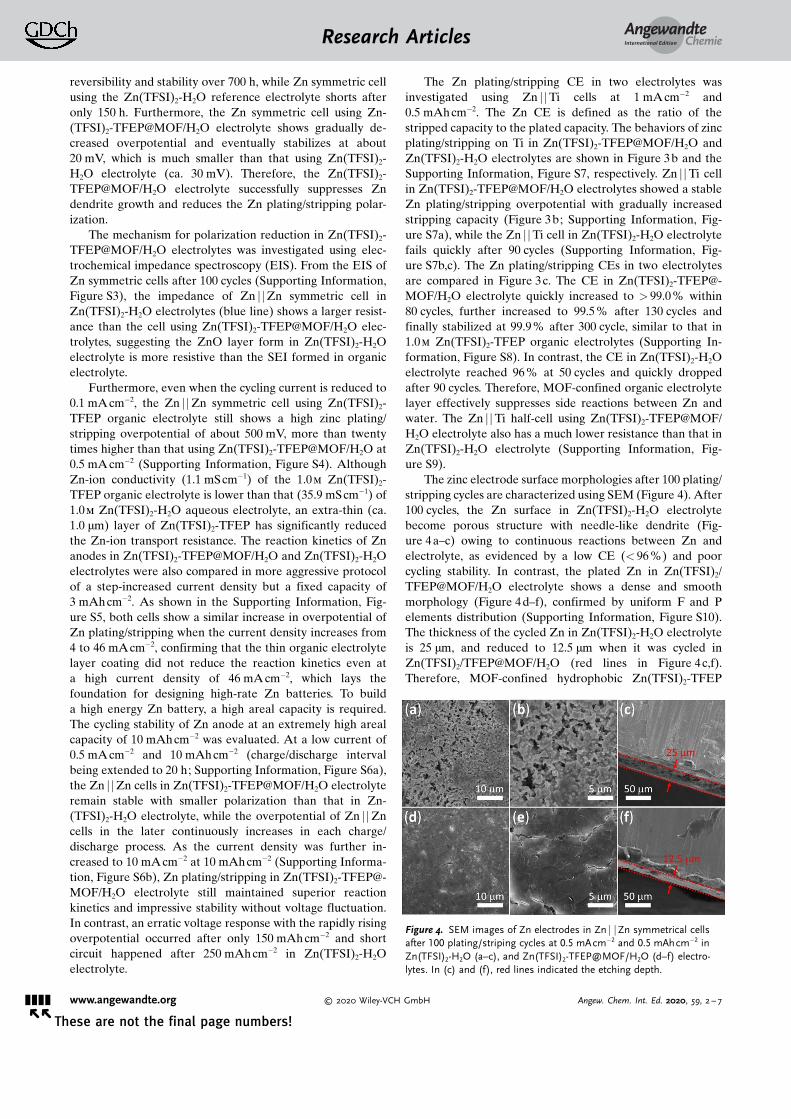
The zinc electrode surface morphologies after 100 plating/stripping cycles are characterized using SEM (Figure 4). After100 cycles, the Zn surface in Zn(TFSI)2-H2O electrolytebecome porous structure with needle-like dendrite (Fig-ure 4a–c) owing to continuous reactions between Zn andelectrolyte, as evidenced by a low CE (< 96 %) and poorcycling stability. In contrast, the plated Zn in Zn(TFSI)2/TFEP@MOF/H2O electrolyte shows a dense and smoothmorphology (Figure 4d–f), confirmed by uniform F and Pelements distribution (Supporting Information, Figure S10).The thickness of the cycled Zn in Zn(TFSI)2-H2O electrolyteis 25 mm, and reduced to 12.5 mm when it was cycled inZn(TFSI)2/TFEP@MOF/H2O (red lines in Figure 4c,f).Therefore, MOF-confined hydrophobic Zn(TFSI)2-TFEP
Figure 4. SEM images of Zn electrodes in Zn j jZn symmetrical cellsafter 100 plating/striping cycles at 0.5 mAcm�2 and 0.5 mAhcm�2 inZn(TFSI)2-H2O (a–c), and Zn(TFSI)2-TFEP@MOF/H2O (d–f) electro-lytes. In (c) and (f), red lines indicated the etching depth.
AngewandteChemieResearch Articles
&&&& www.angewandte.org � 2020 Wiley-VCH GmbH Angew. Chem. Int. Ed. 2020, 59, 2 – 7� �
These are not the final page numbers!

organic electrolyte layer on Zn surface effectively suppressedwater penetration from Zn(TFSI)2-H2O to Zn surface, whichsuppressed Zn dendrite growth. Here, water was chemicallyblocked by hydrophobic Zn(TFSI)2-TFEP organic electrolytethat is immiscible with Zn(TFSI)2-H2O aqueous electrolytes,rather than physically blocked by a ceramic layer reportedbefore that lacks self-repair capability if it is cracked. TheMOF is just to confine Zn(TFSI)2-TFEP organic electrolyte.Furthermore, the Zn(TFSI)2-TFEP was also reduced at Znplating potential forming a hydrophobic SEI on Zn surface asdemonstrated by XPS below, which can further prevent tracewater dissolved in Zn(TFSI)2-TFEP electrolyte from reactingwith Zn.
SEI Characterization on Zn Anodes
The surface composition of Zn electrodes after 100 cycleswas analyzed using XPS facilitated by Ar+ sputtering (Fig-ure 5; Supporting Information, Figure S11). For the F 1sspectrum in Figure 5, the top surface (before sputtering) of Znanodes recovered from Zn(TFSI)2/TFEP@MOF/H2O elec-trolyte mainly contains organic CF3 species (94.7 %) withminor inorganic ZnF2 (5.3 %). Since TFEP (boiling point40 8C) should be completely removed from Zn in XPSchamber, the CF3 species arise from either of incompletereduction products of Zn(TFSI)2-TFEP or trace Zn(TFSI)2
residue on Zn surface, while ZnF2 is due to Zn(TFSI)2-TFEPreduction. To contrast, no inorganic ZnF2 is detected on Znelectrode from Zn(TFSI)2-H2O electrolyte (Supporting In-formation, Figure S12). After 300 s sputtering on Zn surfacerecovered from Zn(TFSI)2/TFEP@MOF/H2O electrolyte,CF3 peak disappeared but new peak at 688.0 eV was detected,
which corresponded to CF from the reduction of Zn(TFSI)2-TFEP. Upon further sputtering to 1800 s, the inorganic ZnF2
content increased from 78.1 % at 300 s sputtering to 87.5 %.Furthermore, for the P 2p spectrum, the top surface (beforesputtering) recovered from Zn(TFSI)2-TFEP@MOF/H2Oelectrolyte mainly contains organic PO3, which could arisefrom incomplete reduction products of TFEP. After 300 ssputtering, organic PO3 peak disappeared but new inorganicZn3(PO4)2 peak at 134.1 eV appeared. Upon further sputter-ing to 1800 s, Zn3(PO4)2 peak persists. From FTIR and Ramananalysis of Zn surface recovered from Zn(TFSI)2/TFEP@-MOF/H2O electrolyte (Supporting Information, Figure S13),strong P�O bond stretching and bending peaks[10] weredetected, further confirming the formation of Zn3(PO4)2.Zn3(PO4)2 SEI has a high Zn2+ conductivity and this has beenproved by both experiment[11] and theoretical[12] analysis, alsoconfirmed in the Supporting Information, Figure S3. Thedense ZnF2-Zn3(PO4)2 SEI separates Zn surface from tracewater dissolved in the Zn(TFSI)2-TFEP organic electrolytelayer but allows Zn2+ to diffuse through.
Electrochemical Performance of MnO2 Cathodes and Zn j jMnO2
Full Cells
The Zn(TFSI)2-TFEP protected Zn anode was evaluatedin Zn j jMnO2 full cell using tunnel structured b-MnO2, one ofthe most promising cathodes with a high theoretical capacityof 308 mAh g�1 for aqueous Zn batteries, and compared withthat using unprotect Zn in aqueous Zn(TFSI)2-H2O electro-lytes. We first evaluated the electrochemical performance ofMnO2 cathode in two electrolytes using CV at 0.1 mVs�1
using a Zn j jMnO2 cells with a high capacity ratio (Zn/MnO2) of 3.0, and the CV behavior reflects MnO2 behavior.
As in Figure 6a, MnO2 in both electrolytes showed thesame behavior with distinct Mn-ion redox peaks, consistent
Figure 5. XPS features of the SEI on Zn after 100 charge/dischargecycles in Zn(TFSI)2-TFEP@MOF/H2O electrolyte. The F 1s and P 2pspectra are displayed in rows, with corresponding Ar+ sputtering depthprofiling results in columns.
Figure 6. Electrochemical performance of Zn j jMnO2 cells. a) CV ofZn j jMnO2 full cells at a scan rate of 0.1 mVs�1. b) Rate performancein Zn(TFSI)2-TFEP@MOF/H2O electrolyte. c) Cyclic stability and effi-ciency of Zn j jMnO2 cells in two electrolytes with 0.1m Mn(OTF)2 (tosuppress Mn2+ dissolution) at 10 C.
AngewandteChemieResearch Articles
&&&&Angew. Chem. Int. Ed. 2020, 59, 2 – 7 � 2020 Wiley-VCH GmbH www.angewandte.org
These are not the final page numbers! � �

with the previous work.[13] The rate performance of MnO2
cells in Zn(TFSI)2-TFEP@MOF/H2O electrolyte was alsoevaluated. As in Figure 6b, the MnO2 cathodes provideda high capacity of 270 mAhg�1 at a low rate of 0.5 C, and stillmaintain 135 mAhg�1 even at a high rate of 10 C. The rateperformance in both electrolytes are similar (SupportingInformation, Figures S14, S15). At 0.5 C, the capacity basedon the (cathode + anode) mass is 154 mAh g�1, correspondingto an energy density of 210 Whkg�1. The long-term cyclingstability of the Zn j jMnO2 cell was evaluated at 10 C in bothelectrolytes with 0.1m Mn2+ additive to suppress Mn2+
dissolution (Figure 6c). Even with the capacity ratio ofZn:MnO2 at 2:1, the Zn j jMnO2 cells after 600 cycles inZn(TFSI)2-TFEP@MOF/H2O electrolyte still maintain about141 mAhg�1, which is 97.2% of initial capacity with CEapproaching 100 %, while the capacity of Zn j jMnO2 cells inZn(TFSI)2-H2O electrolyte quickly dropped to 59.0 % ofinitial capacity due to low CE for Zn plating/stripping.
Conclusion
Zn dendrite growth and low CE is due to water reductionon Zn anode challenge aqueous Zn batteries. In this work, weseparate the Zn(TFSI)2-H2O aqueous electrolyte from Znanode by coating a thin (ca. 1.0 mm) hydrophobic Zn(TFSI)2-TFEP organic electrolyte on Zn surface that is immisciblewith Zn(TFSI)2-H2O aqueous electrolyte. To avoid the flowaway of hydrophobic Zn(TFSI)2-TFEP organic electrolyte,a thin layer of organophilic MOF was coated on Zn andhydrophobic Zn(TFSI)2-TFEP organic electrolyte was con-fined inside the MOF pores. MOF confined Zn(TFSI)2-TFEPprotecting electrolytes provide several advantages: 1) MOF-confined Zn(TFSI)2-TFEP can chemically prevent waterpenetration onto Zn anode due to the phase separation ofZn(TFSI)2-TFEP organic electrolyte with Zn(TFSI)2-H2Oaqueous electrolyte, and the formed ZnF2-Zn3(PO4)2 SEI canfurther block the trace water dissolved in the Zn(TFSI)2-TFEP organic electrolyte layer; 2) ZnF2-Zn3(PO4)2 SEI canbe self-repaired if it is broken because it was formed by thereduction of Zn(TFSI)2-TFEP organic electrolytes, which istotally different from ceramic layer coating reported beforethat is lack of self-repaired capability. Zn(TFSI)2-TFEPprotected Zn anodes enabled a Zn anode to achievea reversible and dendrite-free Zn plating/stripping CE of99.9%, and Zn j jMnO2 cells with a low capacity ratio ofZn:MnO2 at 2:1 to achieved a high energy density of210 Whkg�1 (based on cathode and anode) and remained97.2% of initial capacity after 600 cycles at 10 C.
Conflict of interest
The authors declare no conflict of interest.
Keywords: aqueous zinc batteries · metal–organic frameworks ·phase separation · reversibility
[1] a) F. Wang, O. Borodin, T. Gao, X. Fan, W. Sun, F. Han, A.Faraone, J. A. Dura, K. Xu, C. Wang, Nat. Mater. 2018, 17, 543 –549; b) L. Ma, S. Chen, N. Li, Z. Liu, Z. Tang, J. A. Zapien, S.Chen, J. Fan, C. Zhi, Adv. Mater. 2020, 32, 1908121; c) H.-F.Wang, C. Tang, Q. Zhang, Adv. Funct. Mater. 2018, 28, 1803329.
[2] a) L. E. Blanc, D. Kundu, L. F. Nazar, Joule 2020, 4, 771 – 799;b) Y. Jin, L. Zou, L. Liu, M. H. Engelhard, R. L. Patel, Z. Nie,K. S. Han, Y. Shao, C. Wang, J. Zhu, H. Pan, J. Liu, Adv. Mater.2019, 31, 1900567; c) X. Wu, Y. Xu, C. Zhang, D. P. Leonard, A.Markir, J. Lu, X. Ji, J. Am. Chem. Soc. 2019, 141, 6338 – 6344.
[3] F. Mo, G. Liang, Q. Meng, Z. Liu, H. Li, J. Fan, C. Zhi, EnergyEnviron. Sci. 2019, 12, 706 – 715.
[4] a) J. Yi, P. Liang, X. Liu, K. Wu, Y. Liu, Y. Wang, Y. Xia, J.Zhang, Energy Environ. Sci. 2018, 11, 3075 – 3095; b) J. J. Hong,L. Zhu, C. Chen, L. Tang, H. Jiang, B. Jin, T. C. Gallagher, Q.Guo, C. Fang, X. Ji, Angew. Chem. Int. Ed. 2019, 58, 15910 –15915; Angew. Chem. 2019, 131, 16057 – 16062.
[5] H. Yang, Z. Chang, Y. Qiao, H. Deng, X. Mu, P. He, H. Zhou,Angew. Chem. Int. Ed. 2020, 59, 9377 – 9381; Angew. Chem. 2020,132, 9463 – 9467.
[6] Z. Zhao, J. Zhao, Z. Hu, J. Li, J. Li, Y. Zhang, C. Wang, G. Cui,Energy Environ. Sci. 2019, 12, 1938 – 1949.
[7] A. A. Talin, A. Centrone, A. C. Ford, M. E. Foster, V. Stavila, P.Haney, R. A. Kinney, V. Szalai, F. El Gabaly, H. P. Yoon, F.L�onard, M. D. Allendorf, Science 2014, 343, 66 – 69.
[8] M. Sogawa, S. Sawayama, J. Han, C. Satou, K. Ohara, M.Matsugami, H. Mimura, M. Morita, K. Fujii, J. Phys. Chem. C2019, 123, 8699 – 8708.
[9] S. Bai, X. Liu, K. Zhu, S. Wu, H. Zhou, Nat. Energy 2016, 1,16094.
[10] a) D. Shakhvorostov, M. H. M�ser, N. J. Mosey, D. J. Munoz-Paniagua, G. Pereira, Y. Song, M. Kasrai, P. R. Norton, J. Chem.Phys. 2008, 128, 074706; b) M. Larzilli�re, M. E. Jacox, J. Mol.Spectrosc. 1980, 79, 132 – 150.
[11] W. Shin, J. Lee, Y. Kim, H. Steinfink, A. Heller, J. Am. Chem.Soc. 2005, 127, 14590 – 14591.
[12] A. Naveed, H. Yang, Y. Shao, J. Yang, N. Yanna, J. Liu, S. Shi, L.Zhang, A. Ye, B. He, J. Wang, Adv. Mater. 2019, 31, 1900668.
[13] W. Sun, F. Wang, S. Hou, C. Yang, X. Fan, Z. Ma, T. Gao, F. Han,R. Hu, M. Zhu, C. Wang, J. Am. Chem. Soc. 2017, 139, 9775 –9778.
Manuscript received: June 19, 2020Accepted manuscript online: July 7, 2020Version of record online: && &&, &&&&
AngewandteChemieResearch Articles
&&&& www.angewandte.org � 2020 Wiley-VCH GmbH Angew. Chem. Int. Ed. 2020, 59, 2 – 7� �
These are not the final page numbers!

Research Articles
Batteries
L. Cao, D. Li, T. Deng, Q. Li,C. Wang* &&&&—&&&&
Hydrophobic Organic-Electrolyte-Protected Zinc Anodes for Aqueous ZincBatteries
A highly reversible Zn anode is achievedby using a phase-separation electrolyte,where aqueous electrolyte is separatedfrom Zn by a MOF-confined thin layerhydrophobic Zn(TFSI)2-TFEP organicelectrolyte and a ZnF2-Zn3(PO4)2 solidelectrolyte interphase (SEI). The Znanode achieves a high Coulombic effi-ciency of 99.9% at 1 mAcm�2 for350 cycles and stable Zn jjMnO2 batter-ies.
AngewandteChemieResearch Articles
&&&&Angew. Chem. Int. Ed. 2020, 59, 2 – 7 � 2020 Wiley-VCH GmbH www.angewandte.org
These are not the final page numbers! � �