research centre rez nuclear research institute - … centre rez nuclear research institute ......
TRANSCRIPT

Research Centre Rez Nuclear Research Institute
Low pressure turbine blades lifetime management – complex
procedure for monitoring and evaluation of blade condition
Jaroslav Brom Pavel Mareš
Alena Kobzová Martin Kronďák
Content
1 – Motivation 2 – Establishment of the project 3 – Project area - NDT of blades 4 – Project area - Chemical regimes 5 – Conclusions
1

•2
1 Motivation
Crack initiation
Fatigue process Pressure side near trailing edge Up to 100 mm from blade root Corrosion pitting
Blade failures First: 1983 Last: October 2016 3rd row of low-pressure turbines
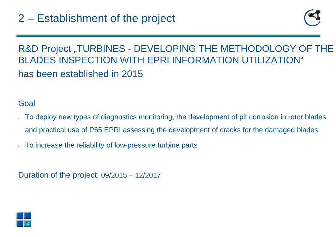
2 – Establishment of the project
R&D Project „TURBINES - DEVELOPING THE METHODOLOGY OF THE BLADES INSPECTION WITH EPRI INFORMATION UTILIZATION“ has been established in 2015
Goal • To deploy new types of diagnostics monitoring, the development of pit corrosion in rotor blades
and practical use of P65 EPRI assessing the development of cracks for the damaged blades.
• To increase the reliability of low-pressure turbine parts
Duration of the project: 09/2015 – 12/2017
3
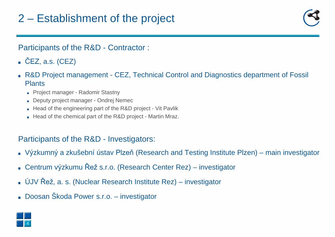
2 – Establishment of the project
Participants of the R&D - Contractor :
ČEZ, a.s. (CEZ)
R&D Project management - CEZ, Technical Control and Diagnostics department of Fossil Plants
Project manager - Radomir Stastny Deputy project manager - Ondrej Nemec Head of the engineering part of the R&D project - Vit Pavlik Head of the chemical part of the R&D project - Martin Mraz.
Participants of the R&D - Investigators:
Výzkumný a zkušební ústav Plzeň (Research and Testing Institute Plzen) – main investigator
Centrum výzkumu Řež s.r.o. (Research Center Rez) – investigator
ÚJV Řež, a. s. (Nuclear Research Institute Rez) – investigator
Doosan Škoda Power s.r.o. – investigator
4

2 – Establishment of the project
Areas of the project:
NDT of blades – Monitoring of corrosion pits – NDT to detect cracks
Material Characteristics Stress analysis Chemical regimes On-line vibration monitoring
5

2 – Establishment of the project – project structure
6
Monitoring of corrosion pits
Material characteristics
Stress analysis – phase 1
Chemical regimes
Reduction of
corrosion
Methodology application
NDT to detect cracks
Turbine inspections
Decision on further
operation Stress analysis – phase 2/3
KTEH diagram construction
On-line vibration monitoring
Determination of ∆σ0 a ∆Kth
Determination of σa a σm
Inputs for simulation a verification
Determination of position and
dimensions of pit
∆σ0 = double the fatigue limit ∆Kth - threshold amplitude of stress intensity factor σa – dynamic strain amplitude σm – static strain amplitude KTEH - Kitagava-Takahashi diagram complemented by the El Haddad curve (KTHD diagram shows the dependence of the cyclic stress range ∆σ on the depth of the corrosion pit c. It allows to predict, for cracks of given length and stress range, the allowable stress range for infinite life)

Detection of corrosion pits and their sizing
3D scanning using a laser scanner with measuring arm or laser tracker
3 – Project area - NDT of blades
7

Verification of the depth measurement accuracy by 3D Surface Scanning was performed by comparing the results with those obtained from light microscopy which showed a ± 20μm match. An example of comparison is shown in Figure 4.
3 – Project area - NDT of blades – corrosion pitting
8
Light microscopy results: 3D scan results – cross-section in the plane of LM (tolerance ±25μm):
depth 76μm (+28μm oxid) × width 403μm depth 74μm × width 398μm
The output from the 3D measurement is the report where the coordinates and the size of the depth are determined for each blade. Attached to the report are also the scans of the blades with the largest pits

3 – Project area - NDT of blades: NDT to detect cracks
Current status Magnetic particle testing as a main method Eddy currents used only in exceptional cases
9
New methodology required

3 – Project area - NDT of blades: NDT to detect cracks
New methodology: Two main methods
Eddy current array testing for initial screening Magnetic particle testing
Supplemental methods in the case of indication detection Dye Penetrant testing Ultrasonic testing using Rayleigh waves Ultrasonic phased array testing (in the case that indication isn‘t through blade)
10

3 – Project area - NDT of blades: NDT to detect cracks
Equipment for eddy current array: Flexible array probe
11
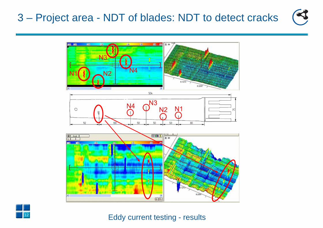
3 – Project area - NDT of blades: NDT to detect cracks
12 Eddy current testing - results

3 – Project area - NDT of blades: NDT to detect cracks
Magnetic particle testing Usage of the magnetic yoke and fluorescent medium Common inspection Not cover 100% surface of blade because of limited access
13

3 – Project area - NDT of blades: NDT to detect cracks
14
Ultrasonic testing – Rayleigh waves This supplemental method is used in case of indication detection or if eddy current method cannot be performed All EDM notches were detected
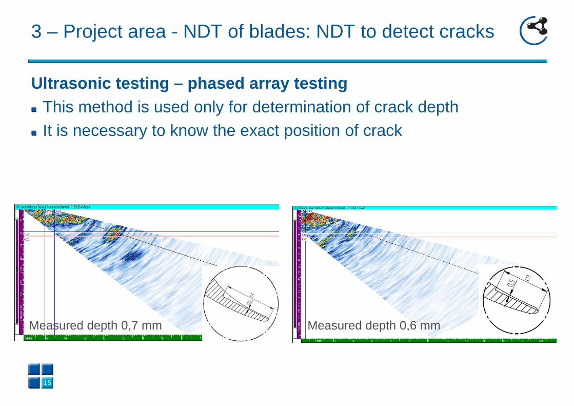
Ultrasonic testing – phased array testing
This method is used only for determination of crack depth It is necessary to know the exact position of crack
15
3 – Project area - NDT of blades: NDT to detect cracks
Measured depth 0,7 mm Measured depth 0,6 mm

3 – Project area - NDT of blades: NDT to detect cracks
Simulation Simulation in software CIVA Simulation of any defect
in any position
16

3 – Project area - NDT of blades: NDT to detect cracks
Penetrant testing This supplemental method is used for verification of detected indications Is not suitable for all blades testing
High difficulty for surface preparation Duration of inspection No measurement record
17

3 – Project area - NDT of blades: NDT to detect cracks
Method Detection Length
determination
Depth
determination
Eddy current X
Magnetic particle X X
Penetrant X
Ultrasonic – Rayleigh waves X
Ultrasonic - phased array X
18
Conclusion Methodology was verified on 9 test pieces This methodology including 3D measurement will be qualified in a frame on national qualification process according to ENIQ documentation

4 – Project area - Chemical regimes (ChR)
Factors have an effect to optimal operation: design, structural material, quality of feed water and makeup water, water treatment, type of operation.
Goals of optimal water treatment are: minimization of corrosion, maximization of boiler effectivity (reduced deposition), maximization of turbine delivery (reduced deposition), reduction of repair and service costs (trouble-free operation and
safety), extension of life-time.
4 – Project area - Chemical regimes
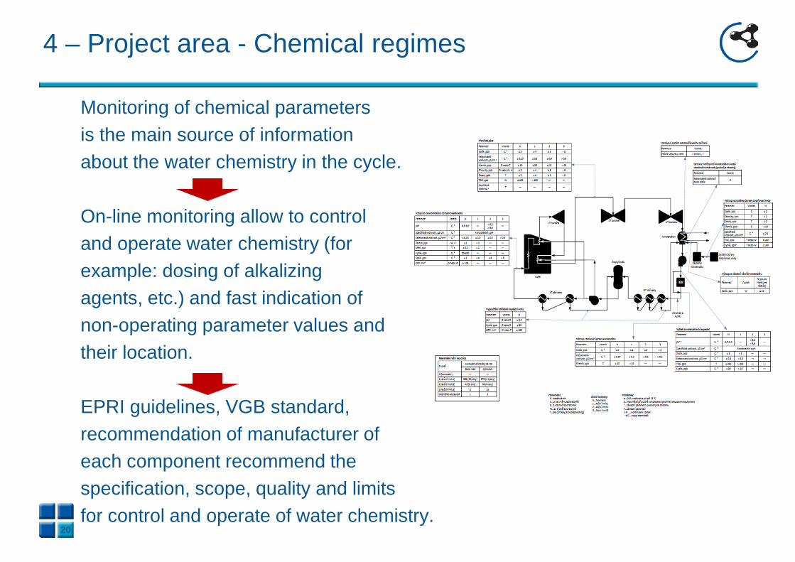
Monitoring of chemical parameters is the main source of information about the water chemistry in the cycle. On-line monitoring allow to control and operate water chemistry (for example: dosing of alkalizing agents, etc.) and fast indication of non-operating parameter values and their location. EPRI guidelines, VGB standard, recommendation of manufacturer of each component recommend the specification, scope, quality and limits for control and operate of water chemistry.
20

4 – Project area – ChR: Monitoring Parameters
Core parameters = recommended minimum for optimal chemical control on-line measurement periodic measurement - pH, - iron concentration - cation conductivity, - carryover - specific conductivity, - chloride - dissolved oxygen, - sodium, - silica
Diagnostic parameters make for finding of operating problems or these are important during the transient states (start up, shutdown, cycling, layup, etc.).
21

4 – Project area – ChR: Sampling points
economizer inlet (feed water)
boiling water (drum units)
main / reheat steam
makeup treatment system
deaerator inlet
condensate pump discharge
polisher outlet
22

4 – Project area – ChR: General Recommendation
Instrumentation for on-line and periodic measurements by
EPRI recommendation is necessary to install .
Detailed scheme of water chemistry for each fossil plant
should be draught.
Control and service of on-line monitoring system should
be ensured.
23

4 – Project area – Chemical regimes: Conclusion
Recommendation for Reduce of Pitting on the Blades Chlorides and sulphates are starter of pitting.
Minimization of impurities input and using of recommended monitoring system
lead to maximum purity of steam, feed water and makeup water (reduce amount of
Cl and SO4) periodic measurement of Cl and SO4 more conservative limit of
cation conductivity
Start of pitting initiation is during the transient states (shutdown and layup)
recommended conditions are environment without oxygen and humidity to 35%
Sampling and analysis of deposits by the procedure should be performed during
the each opening of turbo-generator. Results should be added to LTOs
programme.
24

5 – Conclusion
The introduction and deployment of recommended aging management systems will reduce the risk of unplanned shutdown due to unexpected failures such as blade fracture. Furthermore, the cost of repairing the other components damaged by the breakage of the blade will be reduced.
Application of knowledge from the field of chemical mode will contribute to the possibility of reduction of the pitting corrosion.
25
26
Thank you for your attention
[email protected] [email protected] [email protected] [email protected]
http://ndt.cvrez.cz http://susen2020.cz/