research memorandum - digital library/67531/metadc59338/m...theoreticalsmalyses of the...
TRANSCRIPT

..’.
-v;‘“‘“SECURITY INFORMATION
‘“-”.“-—=%.... :.?–....-,4,-—,,. ,T— “~d+?+-= _ .
copy 377RM E52FO&m --
RESEARCH MEMORANDUM
EXPERIMENTAL INVESTIGATION OF A TWO-DIMENSIONAL
RAM-JET INLET AT MACH NUMBER OF 3.85
By James F. Connors and Richard R. Woollett
Lewis Flight Propulsion LaboratoryCleveland, Ohio
‘1’ss: frcgnctllf.d (,.l[r,r,!.til.) (JhA%!&C.,.G.LL )
<d
‘K \ 1........ ....................................................................
!Yi#[IE OF CFFICER MAKING CHANGE)
.31 vYk\L+,. . . . . . . . . . . . . . . . . . . . . . . . . . . . . . . . . . . . . .. . . . . . . .DATE
-. .:
+., ..+
‘=_.-——.-
P .i
.●
I
.

T ?W3ARME52F04
.
I?ATIOIULAINISORY COMMITTE3 FOR AEROIUWTICS
v
RESEARCH MEMORAI?DUM
*
~ IIWE3TIGATION OF A TWO-DR4RWIOML SPLIT-WING
RA3&lEC Il?IEIAT 141CHN1’41XR(X 3.85
By J&mes F. Connors and Richard R. Wool.lett
SUMMARY
An experimental investi.g@ion of the performam e chsmacteristicsof a two-d3mensionaJ.isentropic diffuser, suitable for split-wimg ram-jet application, has been conducted at a Mach number of 3.85 in theLewis 2- by 2-foot supersonic tunnel. The imlet, which had a 4-inchmaximum depth and a 10-inch span, was mounted on a typicsl wing sectionequipped with a variable exit smd a force-measuring system. 12cessure-recwery and mass-flow data are presented for a range of angle ofattack from 0° to 4°. Aerodynamic force data at zero angle of attackare also included.
A maximum total-pressure recovery of 0.41, corresponding to akinetic energy efficiency of 90 percent, was obtained at zero angle ofattack tith a maximum mass-flow ratio of 0.95. M the angle of attackwas increased to 4°,”the pressrme recovery decreased to 0.34 and themaximum ~ss-flow ratio decreased to 0.91. In every case, a Mu?ge dis-continuity im both pressure recovery and mass flow with a chsxacteris-tic hysteresis was encountered between supercritical and sribcritical.op~ation as a consequence of the twin-duct arrangement of the diffuser.Schl.ierenobservations indicated an asymmetrical subcritical shock,pat- “ :--tern with large-sc&le separation and spLILage occurring on one passageonly. I&e changes in all the aerodynamic force coefficients causedby such asynnnetricalflow make subcritical operation intole?xibleforany flight application.
INTRODUCTION
Theoretical smalyses of the ducted-airfoil.ram jet (r~erences 1and 2) have indicated that this type of power-plant configuration has
● considerable promise for application on lohg-range or interceptor-type.-
aircraft operating at Mach nunhrs of 2 or above. Inadditiort, ‘,-.
7
2 NACA RM E52F04 .
the study by Consolidated Vultee Aircraft Corporation has indicatedthat there are no structural limitations that prevent operation at the *higher Mach numbers and altitudes. This latter conclusion is largelythe result of the development of the can-we combustor with its pro-visions for the cooling of external skin surfaces.
—
A need, therefore exist$ for substantiation of the diffuser Per- Qformance assumed in such analyses. The purpose of the present study,then, is (1) to experimentally evaluate the performance of a two- !F
dimensional difftiserdesigned for efficient”operationat a Mach number ““..:of 3.85 and suitable for ducted-airfoil ?%k-jet-”a~lication and (2) tomeasure the aerodynamic forces on an experimental.ting“engine%nstall~- ““’“’ :tion. Accordingly, an ifiet designed for-both exte~ and inter~l’- “.”:isentropic compression was mounted on a typical wing section and wasstudied over a range of angle “ofattack f~gm 0° to 4° -—. .-J—~, ..
+
4
‘4
CD
“c=
CM
%?
Cp
.C
D
F
The foXlming symbols
inlet capture area}
EmBoLs
are used in this report:
Sq ft h
maximum frontal area of engine, sq ftv’
K@3PMELRa (chord measured from leadiqg edge of cowl lip tobase], sq ft
nozzle-exit area, sq ft,.
etiernal drag coefficient (l)/-)
lift coefficient (L/_}
pitching-moment coefficient (@*c)
normal-force coefficient (l?/*)
propulsive-thrust coefficient (F-D/*)
over-all distance measured from leading edge of wedge to thebase, i%
external tia.g~~
thrust, lb

NACA RM E52F04-~
3
.
L
*2
%
J%
%
N
Po
‘3
Po
‘%
lift, lb
moment arm from leading
free-stresm Mach nuniber
edge of wedge, f%
mass-flow rate through engine, slugs/see
mass-flow rate through a free-stresm tube area equal to Ai,slugs/see
normal force, lb
free-stresm total pressure, lb/sq ft
diffuser-exit total pressure, lb/sq ft
free-stresm static pressure, lb/sq ft
free-stream dynamic pressure (7P&2f2) , lb/sq ft
mgle of attack, deg
ratio of specific heats
simulated cdbustion parsmeter where p equals one plus thefuel-air ratio and z equals the total-temperature ratioacress the cotiustion chaniber
APPARATUS AND FRocEDUIll?l
The e~erimental investigation was conducted in the N&3A Lewis
.,
2- by 2-foo% supersonic tunne~ at a Mach nuniberof 3.85 snd at a simu-lated pressure altitude of 108,000 feet. The *reel am -S ~~~~edat a temperature of-l@ +10° Y. BasedReynolds nmiber was
As illustratedplete model spannedthe center section,supporting sectionsboundary layer was bypassed. The center section was positioned between
m the side sections by sti links of a three-component balaace system(see fig. l(b) for linkage details). A large yoke was used ta connectthe trunnions on the side sections and thus permit chsnges in the mgle -
Y of attack of the model. Mounted downstream emd independent of the
200° A5° F-and at a dew-point temperature ofon the maximum depth of the wing (4 in.), the
..
343,000.
in the perspective drawing (fig. l(a)], the conL-the tunnel and consisted of three sepsra.teunits -which was of test interest, and the two side orthrowh which the low-energy air in the tunnel
--

.
4 ~
model, a variable-exit plug was e~byed to regilate the
I?ACARM 3522?04
.
inlet backpressure. ~or+ant over-all.dimensions of the model are given b the
* ‘schematicdraw3.ngof figure l(c). Pressure instrumentation (fig. l(d))consisted of total- and [email protected] mounted at the diffuserexit and immediately upstresznof the variable outlet. “In addition,static-pressure taps were located ou the base of the model for evalu-ation of the base pressure tare loads.
The supersonic diffuser initially investigated was designed forboth external and internal isentropic compression. The external com-pression waves were focused at the lip of the cowl and reduced the flowMach nuniberto 2.38 at the entrsnce, while the internal compressionwaves intersected the centerbody suface in a distributed manner andfurther reduced the Mach nmiber to 1.40 at the throat. The requiredexternal and internal contours were conveniently derived by utilizingthe reverse of two Prandtl-Meyer expansions in series. A correctionfor the displacement thiclmess of a fully turbulent boundary layer wasmade to the centerbody contour by using the method of reference 3 eventhough the pressure gradients experienced were in excess of those forwhich the theory might be expected to apply. It was pssumed that aninitially turbulent boundary layer could be assuredby the use of artif-icial roughness on the leading edge of the centerbody.
To overcome the st&rt@ problem engo~tered wlthhigh,internal-contraction raticm, the imlet was designed for variable geometry byproviding for a longitudinal .yunmnentof the center wedge. This trans-lation was produced by a small.electric motor &d screw arrangementinstalled inside the centerbody. To eliminate edge effects and tomaintain a two-dimensional flow into the inlet, aud also to permitschlieren flow observations, glass plates were mounted at the sides ofthe compression wedge. ~
The subsonic portion of the diffuser was designed for an avera e~angle of divergence between the cowl and the centerbody walls of 10 ,
w?nichwas in accord with the data presented in reference 4. However,this mibsonic passage was further modified to acccmmdate a very smalJdiffusion rate near the throat for increased sho,ckstability; a maximum‘divergence angle of 14* existed at the exit of this $fisonic diffuser.
From results of experiments with the variable-gecgnetryinlet, anoptimum internal contraction was determtaed ad a ftied-geometry dif-fuser was fabricated. The contours of the variable inlet were modifiedfor the fixed-geometry configuration in order to increase the capt~emass flbw and decrease the cowl pressure drag. Coordinates of theoriginal and modified inlet are given in figure l(e).
Cold-flow experiments were conducted wherein the simulation ofheat addition was effected by means of a variable-outlet restriction= -
.s
---
K1’1+mN—
.
.
.._- i!.A
.-—
●“”–
—.
—

-.
NACA RM E52F04 5
.
The exit plug was mounted’independent of the model to allow the balance
●system to measure forces that were the same as that of a rem jet withburning and choking in a constsnt-area duct. Tare forces acting on thebase, the glass side plates, md the instrumentation lines were evalu-ated smd the appropriate corrections made. Complete pressure data were ‘taken over a range of exit plug positions at @es of attack of 0°, 1°,20, 30, end 40.”
$ REHJUC’S AND DISCUSSION?m
One of the most difficult problems that arises in the desi~ ofhigh Mach nunber inlets is that of predicting the effects and the natureof the boundary layer along the compression surface with its strongadverse pressure gradients. Some interesting schlieren photographs of .the air flow along the contoured center.wedge are pregented in figure 2:With a Smooth leadbg edge (fig. 2(a)), there was a characteristic thick-ening and thinning of the olmemed boundary layer as it developedalong the compression surface. This flow pattern is interpreted as a
. separation of the laminar boundary layer, followed by reattachment.Transition to a turbulent layer is believed to have occ~ed by the timethe flow entered the diffuser. With the large adverse pressure gradi-
h
ents encountered here, separation of the lsminar boundary layer wouldbe expected theoretically, as indicated by the predictionof a laminar
i separation point by the method of reference 5 (see arrow on fig. 2(a)).On further inspection of the schlieren photograph, it is observed thatthere are discontinuous lines or striations within the apparentboundary-layer region. The reason for t@is is not known. Subsequente eriments showed that the addition of leading-edge roughness (a
T1 8-imch band ofnurber 100 Carborundum grit) would alter the flow pat-tern along the compression surface to that shown in the schlierenphotographof figure 2(b). The action of the roughness is presmblyto force transition to a.turbulent layer which is more stable andresistant to flow separation. As noted in figure 2(b), the observedboundary layer followed the contour of the wedge more closely and indi-cated no flow separation. However, the over-all pressure recovery ofthe inlet was somewhat lower (2 or 3 percent) with the use of leading- -edge roughness. Consequently, no further consideration was given tothe use of artificial transition, and the data wiJL be presented onlyfor the inlet with a smooth leading age.
.
Qriginal Isentropic Inlet (with Variable Geometry)
. The original inlet desi~ incorporated a large amount of titernalccmqycessionwith provisions for a varisble internal-contraction ratioto satisfy the starting requirements. The opth diffuser performsace
c obtained with this configuration at zero angle of attack was a ms.ximm

6
total-pressure recovery P3/P~ of 0.41 and
cd mass-flow ratio ~mo of 0.75. These
NACA RME52F04
“
a corresponding supercriti- —results were obtained with - “w
an internal-contractionratio that appro~ted the Kantrowttz-Donaldsonlimiting value (reference 6) corresponding to the design inlet Machnumber of 2.38. Larger internal-contractionratios could not beimposed on the flow without expulsion of the normal shock because ofpressure feedback smd separation of tie boundary l&yer in the conver-gent passage.
EkM.ierenpholographs of the flow patterns obtained with thisinlet at optimum tip projection and at zero-angle of attack are pre- ““sented in figure,3 for both supercritical.and subcritical operati~-conditions. As may be observed in the photograph of the.supercriticalflow pattern (fig. 3(a)], the compression shocks emanating from thecont~ured centerbody coalesced well ahead of the cowl lip with a 1resultant large s.mcsuntof flow spillage. This resultedfrom the factthat the inlet was designed for optbperformsmce with a more fullyretracted centerbody, that 1s, with mare internal contraction.
As the flow became subcritical, there occurred a large disconti-nuity in both pressure recovery and mass-flow ratio. Concomitantly anasymmetrical shock patta?nwas observedat the inlet (see fig. 3(b)\.In the bottom passage, the flow had completely separated up to the -leading @ge of the wedge with subsonic or possibly reverse flow in theinlet while in the top passage the flow maintati~ its supercriticalshock pattern. This phenomenon wi.11be discussed more ftiy in con-nection with the fimal mo~fied inlet.
The possibility of obtaining additional internal compression.andcorrespondingly higher pressure recoveries by means of variable geometryappeared to deyend on the development of a boundary-layer control sys-tem that could adequately cope with the feedback problem. In the pre-sent study, tunnel limitations, associated with the large size of themodel, prevented incorporation of a bleed system involving flow spil-lage into the side passages.
Modified Isentropic Inlet (with l?tiedGeometry)
In order to arrive at a more practical aerodynamic configuration,some modifications were made to the original inlet. The inlet lipheight was increased to capture a larger free-stream tube of air andalso to reduce the cowl pressure drag by reducing the projected frontalarea. Schlieren photographs of the shock pattern (fig. 3(a)) were thenscaled to establish the foccil.point of_the compression waves emanatingfrom the wedge surface, thus locat~ the desired lip position for the
—
-. as
_cu.._
-.
.-
*.
f
..
—
—
—..
—-.
“k -

MICA RM E52F04
modified cowl. The ‘internalflow passages were● the Kmtrowitz contraction ratio on the flow as
vsriable geometry data.
7
also reworked to imposeindicated from the
The performance of this configuration at zero angle of attack ispresented in figure 4. A maximum total-pressure recovery of 0.41, cor-responding to a kinetic energy efficiency of 90 percent”at Mach num-ber 3.85, was obtained with a supercritical mas~-flow ratio of 0.95.The corresponding schlieren photograph of the inlet flow during super-critical operation (fig. 4(a)) indicate~very little flow spillage,and the oblique shock wave from the leading edge a~peared to interceptthe cowl lip very closely. Unfortunately, a small scratch in the glassoccurred immediately ahead of the top cowl lip and care must be exer-cised in locating the leading edge. As tiustrated by the data(fig. 4(a)),.there was again a large discontinuity in both mass flowand pressure recovery betwe~ critical smd mibcritical operation. Thislarge detrimental.change in engine operating conditions was not of themagnitude ordinarily experienced with titernal.contraction diffusers;it was accompanied by a pronounced hysteresis loop and by an asymmetr-icalsubcritical shock pattern as shuwn in the schlieren photograph(fig. 4(b)). At zero angle of attack this asymmetric separation patternwould establish itself in either the top or bottom pas=ge tith ~ aPP=-.ent random selection. This effect was a consequence of the twin-ductarrangement of the diffuser. The hysteresis loop in the curves is
1 explained by the fact that there is a range of outlet-area conditionsfor which flow continuity can be satisfied by either of two flow pat-terns at the inlet, (1) supercriti.caloperatio~ with high-pressurerecovery and a high mss flow through the tit or (2) low pressurerecovery and a low mass flow through the exit, which is made possible,in a multiduct system, by one passage undergoing flow reversal andactually spilling flow out of the front of the model. That some of the”flow actually circulated around the centerbody (entering the top pas-sage and discharging from the bottom passage) is indicated by theobservation that the *critical mass-flow ratios were less them ha3fof the supercritical value and that the top pas=ge maintained the same -flow pattern (and thus had the same mass flow entering) during bothsupercritical azuisubcritical engine operation. During subcriticaloperation it was obsened that the angle of the wedge formed by theseparated flow varied with the engine exit srea in order to spill moreor less mss flow as required by continuity considerations. The elimi-nation of this twin-duct interaction may possibly be acccnqlished byequalizing the pressures in the top and bottgm passages by means ofinterconnecting cha2nels (reference 7).
.In figures 5 to 8, the performance curves foy this modified isen-
tropic inlet are presented for imgles of attack of 19, 2°, 3°, and 4°.
t In general, the trends were quite similar to that obtained at zero

8..5. -----
NX!A IUKE52F04
mgl.e of attack. At each @e of attack, there again was the charac-teristic hysteresis loop and sficritical asymmetrical shock pattern.As the angle of attack of the nmdel was increased, the critical value “’of outlet-inlet area ratio increased and thus indicated a reduced backpressure on the diffuser. Therefore, for each supercritical exit con-dition there’is a limiting an&Le of attack”~elow which the asymmetricinlet flow pattern and the attendant hysteresis is avoided. Thus, ifit were specified for this e-e operating with fixed geometry andconstant heat addition (and thereby constant inlet back pressure) thatthere canbe no sticriticsl operation at a maximum angle of attackof 40, the performance at zero angle of attack would thenbe limit+toamsximum recovery of 0.35.
The effect of angle of attack on maximum total-pressure recoverys& supercriticalmass-flaw ratio is shown h the sumnary curves offigure 9. As the angle of attack was increased from O0 to 4°, themaximum pressure recovery decreased frmn 0.41 to 0.34 and the super-critical.mass-flow ratio decreased from 0.95 to 0.91.
At positive angles of attack, the flow consistently sepsrated sub-”critically and spilled from the top pass~e~- It was also noted that; asthe inlet was moved through the angle-of-attack range from O0 to 4°, theextent of the lsminar boundary-layer separation off the top compressionsurface increased quite markedly (compare figs. 4(b) and 8(b)).
Some total-pressure profiles (tidicative of the velocity distribut-ions) across the diffuser exit are presented in figure 10 for the con-ditions of maximum recovery at each angle of-attack and for a t~icalsubcritical.point at zero @e of attack. In each case, the flow wasfou?i.to separate from the centerbody walls. This was probably a con-sequence of the subsonic diffuser desi~ h which a short len@h witha resulting high diffusion rate was specified. As expected, the dif-ference in profiles between the top and boilimapassages increased withangle of attack. The prof+les for sticritical operation (fig. 10(b))again indicate the possibility of flow reve’isalin the bottom passage.
.
— *.
-.
--.
._..
. .
With flcm”reversal the pitot pressure probes would have180° to measure the true total pressure.
,
Aerodynamic Force Coe$f’icientsat Zero Angle of
to be rotated.- -.
—
.-
Attack .—:-
Unfortunately a breakdowp of the balance system premnted the com-,.:
plete range of force data from being obtaiti”dand limits the discussion :
to zero angle-of-attack data and to the slope of the nornkl force curve - ‘“obtained.from Mmitedulata. The force coefficients are present in
%
~,.
figure Il.as a function of the simmlated ccimbustionpemmeter U ,which is indicative of the mount of heat releasein the flight model with burning and choki~ in a
tl&t would’beconstant-ties
re&dredduct.
r“-- :,
—

n)CA4Cn
:T WKiI RME52F04 9
.
As such, the magnitudes of P2% are beyond the range of present-dayhydrocarbon fuels. Of course, in the practical flight configuration
B convergent-divergent exhaust nozzles would be employed so that muchsmaller values of p% would be demanded of the ccmibustorand cor-respondingly smaller values of available thrust would be reelized.
These force data serve primarily to illustrate the intolerableoperating conditions obtained as the inlet flow pattern beceme asym-metric. As a value of the simulated codmstion parameter p% ofapproximately 7.1 was slightly exceeded, the maxhmm propulsive thrustcoefficient Cp of 1.40 decreased to zero and the external drag coef-
ficient CD was doubled from 0.3 to 0.6 as the engine operation became
subcritical. me absolute magnitude of the supercritical CD of 0.3
was much greater than calculated values showing a maxhmm of 0.2. Thisdiscrepancy may be attributed partly to error in the balance measure-ments and partly to such tunnel factors as tunnel side-walJ interfer-ence effects sad flow deviations of the air stream relative to thetest-section walls which would effectively put the inlet at a slight-e of attack.
Further illustration of the adverse subcritical.operating condi-. tions is given in figures H(c) and M.(d), where the discontinuity is
evidenced by a large change in both lift and pitching-moment coeffi-cients. These effects may be illustrated by the following example. If
\ it were assumed that the adverse shift in pitching-moment coefficient(~ = O.27) were of the same order of magnitude at 4° angle of attack
as obtained at zero, the wing would be sti~ected to an abrupt clxmge in ,the center of pressure location equal to approximately 9 percent of thechord. Finite values of CL and CM obtained with supercritical- ;
operation presumably result from a slight flow deviation in the tunnel,inasnnzchas the model was installed parallel to the tuunel floor forthe zero angle-of-attack case.
ISufficient force measurements were taken at a 2° angle of attack :
to indicate that the slope for the normal force curve was
mere ~N is referencd
from the leading edge ofson, the two-dimensional.of attack is
dc~—=da
0.025/deg
to the wing plan srea with a chord measured ~
the cowl lip to the base. Byway of compari-Ackeret value for thin wings at small angles ‘,

10 NACARME52F04
dC~ 4sda
0.019/deg— = 180~~ =
The contribution of the internal flowat angle of attack is
Thus, the
()dCN—=du
theoretical value
to the normal force coefficient
()2X Ai
E ~=0.003/deg
for the slope of the normal force curve is
(ICN~ = 0.022/deg
SUMMARY OF RESULTS
A preliminary experimental investigation of a two-dimensionalisentr~ic inlet &i&ble for”split-wi& ram-jet application yieldedthe following results at a Mch number of 3.85:
1. At zero em~e of attack a ~ total-pressure recov~ of0.41, corresponding to a kinetic energy efficiency of 90 percent, wasrealized with a supercriticeJ_mass-flow ratio of 0.95.
2. As the angle of attack was increased to 4°, the maximum total-pressure recovery fell off to 0.34 and the supercriticel mass-flowratio decreased to 0.91.
3. A large discontinuity in both mass flow and pressure recoverywith a characteristic hysteresis was encountered between critical andsubcritical operation as a consequence of the twin-duct arrangement ofthe diff!user. Corresponding schlieren photographs showed a asycmletri-cal subcritical shock pattern with flow spillage occurring out of onlyone of the passages.
4. The use of variable geometry did ~ot result in the attainmentof internal contracti~n ratios any greater than the Kentrowitz limitingvalue because of-pressure feedback andposeible sepexation of theboundary tiyer.
5. With a value of the simulated combustion ~arameter equal b 7.1,a maximum propulsive thrust coefficient of 1.4, based on the maximumfrontal area of the engine, was obtained at zero’@e-of attack. Largechanges in all the aerodynamic force coefficients caused by twin-ductinteraction made subcritical operation intolerable.
.
.
.
—
.
w-—

NACA RM E52F04.
Lewis Flight Propulsion Laboratory
1.
2.
3.
4.
5..
7.
ITati&ml Ad-%.soryCmmittee for Aeronautics
EuJ.,
Clevelsnd, Ohio
Paul R., and Gsmmal,
REFERENCES*
A. A.: An -Sis of Ducted-Airfoil
XL
Jets for su~ersonic Air&f’t. NACA RM L?124, 1948.
Anon.: l%almation of Supersonic Split Wing Ram Jets. Convair Rep.I?o.Zl&9136-001, ConsoUdated VU1.tee“AircraftCorp., l&zy,1949.(contract No. w35-038ac 17145) ●
Tucker, Maurice: Approximate Calculation of Turbulent Boundary-Ia.yerDevelopment in Co~ressible Fluw. NACA TN 2337, 1951.
Patterson, G. H.: Modern DLMuser Design. Aircraft Eng. vol. X,no. 335, Sept. 1938, pp. 267-273.
Low, George M.: Sia@if ied Method for Calculation of CompressibleIaminar Boundary Layer with hbitrary Free-stream PressureGradient. NU2A TN 2531, 1951. .
lQux&owitz, Arthur, ami Donaldson, Coleman dup.: Fre15minn Wves-tigation of Supersonic Diffusers. NACA ACR L5D20, 1945.
—
Leissler, L. A., and Hesrth, D. P.: Preklminn Investigation ofEffect of Aagle of Attack on &essure Recovery and Stability ~-acteristics for a Vertical Wedge Nose Inlet at ~ = 1.90. NACARME52E14, 1952.
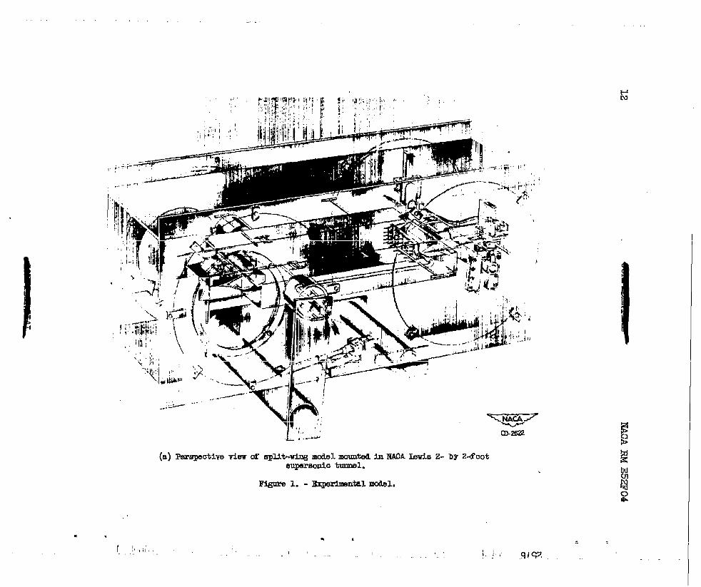
(a) Farspective view of .qMt-wiw mdel -M in IWA Lad.. 2- by 2-footaupamd.o tmmd.
Flgm?cI 1. - Ibp9rklntal modsl,
m-2G2
I

liACARM E5Zt?04
*Center aectlon
(b)Detail d bdenoe -es.
to.375°
t
-~
lo. oo”- 1
I I I .-..
(o)E!chemtiosketohofmodelsharinghqmrtemtUmeneions.
Figure1.- Contizmed.Experimentalmodel.

14 NRCA RM E5ZI?04
.
w
O Pitot tubeU Static tube
kw’liwk.,d . .
-.—
Ny
m
.
Diffuser-exit rake (section A-A, fig. l(c)) —.
kwtid 9A64”. . .——
Combustion-chmber-exit rake (section B-B, fig. l(c))
(d) Pressure instrumentation.
Figure 1. - Continued. Experimental model.
.

. . * 2576 , ,
7x Y Y’
4.9701.647 -----5.0361.693-----5.136 1.753 -----5.1?8 1.7455.255 1.616 1.7665.335 1.a77 1.8155.435 1.920 1.8655.535 1.949 1.s053.535 1.9M 1.9363.7351.2661.9605.625 1.991 1.97’85.93s 1.997 1.9896.035 2.W3 1.997
5.17.91,740 1.7405.235 1.7E3 1.7636.s52 1.797 1.7975.435 1.829 1.6296.53S 1.8561.6565.636 1.8711.8716.72.51.877 1.8776.035 1.877 1.8776.065 ----- 1.8776.265 1.874 1.8776,425 I.Elm 1,877
8.635I
1.8776.689 1.8756.9356,9057.o857,1657,2257.5657.5!35
.0.525 11..2711.6671.6631.2361.B211.Elm1.7&)
;
IIi!)5:
x D D’
o o.m25 O.(X3Z.335 .017 .017.%35 .029 .029
1.0S5 ,c56 ,06’9
1.565 ,096 .0982.095 .3.64 .154z.5a5 .2%5 .2353.085 .s9 .SW3.565 .476 .4784.0S-5 .6&9 .6664.565 Ab2 .9025,o65 1.162 1.1625.665 1.42s 1.4105.785 1.526 1.4755.2& 1.579 1.5005.965 1.6M 1.5136.C1351.815 1.51S6.335 1.595 1.50s6.565 1.583 1.4907.066 1.475 1.4437.565 l.$m 1.s62e.065 1.23$ 1,2386.563 l.10$ 1.3059 .0E!5 .961 .9619.5= .614 ,814
LO.(M5 .6W .2601o.585 .5CX3 .6LM
(e) Coordinate dliwnaioDs of orieiml an6 mdifled inlet.. .2hde4mctlom iticate uedlfic.tionato CUlgiml design. Rim3 ml.um af y, z) m6 D are the cWrMA-S!3 of tbn rmllfied In.lwt.
[email protected] 1. - concluded. Expm@ntd ImdJY1.

.
(.) With EKIOth kdhq edge.
j
F@m 2. - Sclillcuwn*-piU! of flov d(xlg Ocwn’eedon mxcfaoee. Ii=
● ✎
9LSZ ‘ ‘

‘IiM@ii@
m~:? “’:”. ‘“’”‘“ “-’”(b) With rough leaUng ❑dge,
Fi@m 2. - Ccmoluid.. SohU- @ot@gmpba of fl.m almg c.mpmdon mmfaom.
!.,
‘“=

18 MCA RM 1352F0
w -T ---- ‘- -’~il~’- -~” ““:‘“=” ~ ,:-,”.‘-~.
:*:”::-* ‘g—
----- . ---- ._--. ., -.-, -<J. -- -..> ---- .,: >=,-- _ - –-=. — .—. -
,:. .-,
=. . .=-,,
.,..--,.-
.-
K./ ‘-.
(a) Superoritiuslflow p3ttern.
Figure 3. - Sohl~eren
/!2!2 “-.”—.—.---”3 -
(b)Suborttioalflowpattern.
photo@’sphsofshookoonfi@ratlonobtainedtithopttim tQ pro Jeo=on,
—...--
——. .
4 .,,
origird inlet at .
.
.
4
w
-

i
.1 .2 .3 .4 .5 .6Outlet-inlet area ratio, A4/Ai
2576
# .
0 .2 .4 .6 .8 1.0
Mass-flov ratio, IaJ%
1 (a) Variation of total-pressure recovery with outlet-inlet area ratio and mass-flow ratio. ‘
Superoritioal tlow pattern Suboritlcal flow pttem .
(b) 130h11.smwn photagrapbs of f lcw at d.iffuear Inlet.
Figure 4.
x%%- Dlff user pmfonmnoe at zero qle UP attaok.

1’
.4II1 \1I
,3 I7I 1i
b \II
\
I
!.2-
I
iXL -1
.1 .2 .3 .4 .5 .6
Outlet-inlet area ratio, AJ%
o .2 .4 .6 .8 1.0
Ka=3-flow ratio, m.J~
(a) Vaxiation of tatal-messure recovery with outlet-blet area ratio and mass-flow ratio.
I
!I
1
SUb~ltiml f- pattern\t+acA/
(b) Ekhlieren photcgrqiw CU flow at diff.ner inlet.—
C-29818
mgllre 5. - Dlffumr perfmmnce at 1° ewla d attaok.
I nl r--l

I
# ,.
0 .2Mass-i;
2!i76 . ,
.8 1.0w ratio; 6GlJ~
(a) Variation of total-pressure recovery. with outlet-inlet, area ratio and masfi-flow ratio.
+
Superoritloal Iloq psttern Subcritical fl.cw~ttern
(b) Sohlleren phot.ogP@M of flow at dlffueer inlet. C-29819
mgure 6. - Mffueer perfommoa at 2° angle of attaok.

-=
Io .2 .4 .6 .8 1.0
Mase-fl& ratio, IQJ%
(a) Variation. of total-pressure recovery with ou’tlet-hlet area ratio and mBB-flow ratio.
,,
SUprcrltical flov pattern 8uboritl=l flow gattem
(b) SchUerem photograpba aC flow at diffuser inlet.~
Figuxe 7. - Dlffu8er pe?.f~ at 3° [email protected] M attack.
(. Ii, .1’1 9L%+ ‘

●
<0 .4
P--
~ II
* ,3h
ou Ialh
\ _
$m .20k
J
~
I
.1 .2 .3Outlet-inlet
(a) Variation of
4,2576
$
0 .2 .4 .6 .8 1.0
I&ee-flow ratioj me/~
total-presmre recovery with outlet-inlet mea ratio and mass-flow, ratio. ,
C-29821
(b) 6ohUeren phototxwb of sqmoritical flow pattern at Uff user.inlet.
Eigure 8. - Dtifumr pmfomeno e at 4° angle af attaok.
.

NACA RM Z52F04
.
.
0 2 3 4Angle of attack, CL,deg
Figure 9. - Effect of angle of attack on~imum total-pressurerecovery and supercritical mass-flow ratio.
5
NCn4m
r
—,
.
.
P
@./* . . . .*

,
KhCA RM E52F04 25
.
..
,,. -
.-,.
. .
.
.
(a) Angle of attack, zero; (P&Po)mx, 0.41.
.6
.5/
/ ‘
/
\ !
.4❑
1{
Top
o ,
.3
t
. i.C
1
.6 subcritical. -
‘/.5 / [
o ,.’,
/ /ToP
.4Bott Om /‘x }1
/- ,
.3 !0 .2 .4 .6 .8. 1.0 1.2
Distance out from centerbody, in.
(c) Angle of attack, 1°; (P#Po)maX, 0.41.
,e 10. - Total-pressure profiles across diffuser exit.-.

.6
.5
.4
.3
NACA RM E5Zl?04
. t
fP(d) Angle of attaok, 2°; (P#PO)mx, 0.395.
.6
v [
/ ‘5’1 /.5
Bottom,f{,\ “ -
/ n \;
/% 1.
I‘A I(
.4// ToP
/“ \~/’ /0
.3 m A I
{ ?a /
Q r
“= (e) Angle of attack, 3°} (P#PO)mx, 0.36. I.6
.
.5A \
/’.4
I
//
/.5 A
iF + —
.20 .2 .4 .6 .8 1.0 .1.2
Dlatance out from centerbody, In.
(f) Angle of attack, 4°; (P#P~)mx, 0:34.
Figure 10. - Concluded. Total-pressure profiles acrossdiffuser exit.
—
.
-r
....—
.
k“:”
,
.. .
.-
—
——
.
-AJWf?wlmewk

NACA RM E52F04
1.6
.4
0
-o 4
,
I 11I!
Cp / a
II/I
II
/1I
1
IIIv
I 1
I I
/ 1I1
I II I
/ II
I
III
1
1
. (a) TQrust minus drag.
.,
Figure 11. -combustion
Simulated combustion parameter, I-L’%
(b) External drag.
Force coef~icients as function of simulatedparameter IL2T at zero angle of attack.

-.
.-—.. .
r
0
-. 4
.-.8
-1.2
.4
.3”
. . 2
0
NACA RM E5ZF04
. h CLI 1
I I
I 1,1 I
I II [
iIr
I i
I II,, 1
~ .!
2 3 4
(c) Lift.
/ </
I/ I1II 1,I
I 1’ ‘I I
1 I“J I
I ~II I
CM ,*
( I85 “. 6 _.7-..
Simulated combustion parameter, V%
(d) Pitching moment.
Figure 11. - Concluded”..,Force”cdefficients assimulated combustion parameter u% at z,eroattack.
fynctionangle of
.—---
,.,,
-.
—
..
...
*
—-
.=
.
*
...
—
.-:
u-—.
—.. “=-
.-
— - —-.5 -–.’
~ .: ... -.,. .. -“
.
NACA-Langley -8-11-52 -400