research memorandum - nasa · calculation incorporated the measured radial variation of stagnation-...
TRANSCRIPT
RESEARCH MEMORANDUM
APPLICATION OF RADIAL-EQUILIBRIUM CONDITION TO AXIAL-FLOW
TURBOMACHINE DESIGN INCLUDING GONSJDERATION OF CHANGE
O F ENTROPY WITH RADIUS DOWNSTREAM O F BLADE ROW
BY James E. Hatch, Charles G. Giamati, and Robert J. Jackson
Lewis Flight Propulsion Laboratory C leveland, Ohio
CLASSIFICATION G:!P?CFD
m, UNCLASSIFIED
NATIONAL ADVISORY COMMITTEE FOR AERONAUTlC9LY5SZEY @Wv -1
https://ntrs.nasa.gov/search.jsp?R=19930088148 2018-08-27T10:08:11+00:00Z
(H
(D E:
NACA RM E54A20
APPLICATION OF R A D I A L E Q K I L ~ I U M CONDITION 'Po A X I A L - F L O W TuRBoMAI=ElXE
DESIGN I E L U D I N G CONSDERA!I!ION OF CHANGE OF ENTROPY
By James E. Hatch, Chasles C. G i a m a t i , and Robert J. Jackson
An investigation w a s made o f t h e va l id i ty of application of the simplified-radial-equilibrium equation t o axid-flow turbomachines. Two types of calculations based on t he assumption of simplified radial equi- librium were made of radfal distributions of axid veloci t ies for cam- parisons with data from several compressor configurations. One type of calculation incorporated the measured radial variation of stagnation- pressure losses by means of a t e r m in the radial-equilibrium equation expressing the radial variation of entropy. The second type of cdcula- Cion did not include this t e r m .
In order t o compute accurately the radial variation of velocit ies, it was necessaxy in general t o include the measured stagnation-pressure losses in t he sinrplified-radial-equilibrium equation. The asamption of zero radial gradient of entropy w-as invalid for the cslculation of ve- loc i t i e s at axial s ta t ions more than one or two blade rows damstream frm a region of uniform entropy. At an axial s ta t ion following severd stages of a multistage campressor, large discrepancies were observed between measured veloci t ies and velocit ies computed from the simplified- radial-equilibrium calculation which neglected the entropy term, wbile the incorporation of the entropy term led to calculated veloci t ies which agreed closely w i t h data.
Very close agreement was observed between the velocities calculated by using an entropy gradient and measured veloci t ies in the boundary- layer regions at the hub and t i p while the second type of calculation, w i t h the entropy gradient neglected, was not correct. This trend. sug- gests that the blockage effect of the boundary layer can be taken into account by a design assumption of the bound8z-y-layer stagnation-pressure prof i le based upon available bmdezy-layer loss data.

2
A velocity-diagram design method, based upon the results of this investigation and including the effect of the estimated stagnation pres- -. sues on the design axial-velocity profile, is suggested in this repar t .
LNTRODUCTION
The design procedure currently i n use fo r a multietage axial-flow compressor i e divided into two phases, the f i r s t of which is concerned with the. determination of stage velocity diagrams f o r the met and out- l e t t o the various blade rows, while the second i s concerned with the cr)
selection of blade shapes which w i l l yield these diagrams. In the f k s t phase the radial-equilibrium condition (the radial component of the equation of motion) i s used. This coadition specifies the radial pres- s u r e gradient that is necessaxy t o provide the centripetal force to maintain a curved flow path (refs. 1 t o 3) through the compressor.
been this
This flow
In design work a f o m of the radial-equilibrium condition which has used is given in reference 1 (eq. (14) ) as ( in the terminology of report ) -
equation was derived under the assumption of a x i d l y symmetric i n a fluid of negligible viscosity. When the equation is applied
t o an axial s ta t ion at the inlet or outlet of a blade row, the blad.e- force tern represented by Fr is zero.
In reference 1, the effect of the radial-flow term (- v, 2) of equation (1) on the radial distribution of the state of the gas w a s investigated. This was done fo r nonviscous-flow problems by coqaring solutione obtained by applying equation (1) with solutions obtained by applying a modification of equation (1) (the simplified-radial-equilibrium approximation) which dropped the radial-fiow -term. Far- the purposes of
this analysis, the entropy term (t e) of equation (1) was neglected in these solutions because of the assumptions of nonviscous flou and no heat transfer.
These meth& for inviscid f luids do not account far the r a d vmiation of total-pressure losses which occur across a blade row in a compressor. In order t o include these losses Fn the velocity-diagram calculations, the radW variation i n total-pressure loss can be related to t he ra.dia3. variation in entropy and as such included in the radial- equilibrium calculations. A method of velocity-diagram calculation which includes the entropy term is shown in this report. In order t o ascertain

NACA RM E54A20 3
w Oa 0 03
the effect of the entropy term of equation (I) on the radial d is t r ibu- t ion of the s t a t e of the gas, velocit ies are computed by using a md.5- f ica t ion of equation (1) which includes the entrapy term but drops the radial-flow term (sinrplif'ied radial equilibrium including entropy gra- dient) and are compared w i t h velocit ies computed from a modification of equation (1) which does not include the entropy term and also drops the radial-flow term (einrplified-radieL-equilibrium approximation). These velocity distributions, which are computed for several compressor COR- figurations, axe compared i n each case with measured ve loc i t i e s t o see if it is possible t o predict correctly the stage-velocity diagrams by including the entropy term in the calculations.
The development of the solution including entropy gradient t o the radial-equilibrium equation is presented in the section ANALYSIS OF EQUATIONS. The differences in the assumptions used for this solution and f o r the solutions obtained in reference 1 are dfscussed, and the significance of the entropy term in the radW--equilibrium solution is pointed aut.
The methods used t o adapt the analytical solutions (s-rmplified radial equilibrium including entrapy wedient and simplified-radial- equilibrium approximation) t o measured data are shown i n the section ANALYSIS OF EXPIiBIMEWTAL DATA. The experimental data are taken from configurations described in references 4 t o IO- Ln most cases the data were available only i n the "main-stream region"; however, i n two con- figurations, data obtained near the end w a l l s of the compressors w e r e used to see if the axid-veloci ty prof i les i n the bounda;ry layer could be accounted f o r by the solution based on simplified radial equilibrium including an entropy gradient. The remainder of the data in the sect ion ANAUSIS O F ExPwIMfDEAL DATA i e g r o q e d a s single-stage data or data from middle or end stages of a mult i s tage cqressor .
The sect ion ent i t led AIUdXSIS O F DESIGN TECHNIQUE suggests possible uses of the approximation of simplified radial equilibrium including an entropy gradient i n a design procedure. An exsmple of a fixed-ar'ea velocity-diagram calculation is outlined i n de ta i l .
SYMBOLS
The following symbols are used in this report:
c specific heat at constant pressure, ft-lb/(slug)(%), equal t o P Jgcp engineering units
D diffusion factor (ref. 11)
F blade force, lb/slug
0
-

4
B
E
J
K
P
P
R
r
S
T
t
U
V
VU
W
2
B
Y
e
P
v
- NACA RM E54A20
acceleration due t o gravity, ft/sec2
t o t a l enthalpy, ft-lb/slug, equal to JgH engineering units
mechanical equivalent of heat, ft-lb/Btu *
curvature of path, reciprocel of radius of curvature, ft'l
total pressure, l.b/sq f t
static pressure, lb/sq f t
gas constant, ft-lb/(slUg)(OR), equal t o gR engineering units
radius, f t
entropy, f t- lb/(slug) ( s i ) , equal t o gs engineering units
t o t d temperature, OR
s t a t i c temperature, OR
rotor velocity, ft/sec
gas velocity, ft/sec
absolute gae velocity at s ta t ion where some variablee are unknown, ft/sec
weight flow, lb/sec
a x i d distance, f t
absolute a i r angle, angle between air velocity and axial direction, deg
ratio of specific heats
angulaz coordinate, deg
static density, slugs/cu f t
stage-idet-flow coefficient, (V,/Ut>av
.
Subscripts:
BY average
h hub
.

NACA RM E54A20 *
5
k
m -
r
ref bo n t
8 U
z
. 8
0
1,2,3,. . . n L
radial s ta t ion *ere vaziables are &own
mean
radial d i rect ion
reference
t i p
radial s ta t ion where same vaziables are unknown
axial d i rect ion
tangential direction
pipe inlet or compressor depression tank
axial sta t ion downstream of nth blade row, where the guide vanes are the first blade row.
AEIllLYSIS OF EQUATIONS
Assumptions
The behavior of a f l u i d i n a campressor can be investigated by applying the conbervation laws of matter, momentum, and energy t o the flaw. The assumptions of ax ia l synnnetry and negligible viscosity are reasonable conditions t o specify in order t o investigate thie flaw. U s i n g these sssumptions, the authors of reference 1 developed the fol- lowing form of the conibined momentum and energy equations for a cylin- drical coordinate syatem, where r, z, and 8 are independent variables:
In applying these equations (eqs . (141, (15 ), and (16) of ref. 1 i n the terminology of this report) , the f l u i d was considered t o be inviscid throughout the canrpressor so that the vazirttion in entropy could be caused only by heat transfer. Thus, the entropy term was neglected i n

6 - W A RM E54A20
the solutions presented since no heat transfer w a s assumed. However, i n a real compressor, viscous flaws exist and a radial variation of blade- row total-pressure losses, which gives rise to , a radial entropy gradient, can occur as the viscous fluid passes through the blade rows where large velocity gradients and large wetted surface areas are present.
The effect on axial-velocity profiles of viscous forces which o c m in the space between blade rows is s m a l l compared with the effect on the axial-velocity profiles of losses which have occurred upstream through the blade rows. Thus when the flow i n the space between blade rows is examined, the f lu id i s considered t o be inviscid (hence eqs. (2 ) are applicable) with a radM entropy gradient at the point of interest. The ,Fnclusion of the entropy term i n applying the radial-equilibrium condition may be regarded as a lose correction included in the equations for inviscid flow. In this investigation, an experimental evaluation of the losses is included i n the analytical solutions.
An example of how these concepts can be applied to the slmple case of pipe flow is shown i n the following section. The manner in which the equations are applied is analogous t o t h e manner i n which they are ap- pl ied to ac tua l compressors fo r t h i s investigation.
Significance of Ehtropy Gradient
For application to pipe flow or t o the space a compressor, equations (2 ) are more conveniently
between blade r o w B of written as
In the case of pipe flow, T is a constant throughout the flaw and is equal t o To, and V, P Vr P 0. In order t o apply equations (3) t o an axial s ta t ion downstream of the inlet, the f lu id must be considered inviscid a t this s ta t ion. This condition, along with Ve = Vr = 0, reduces the set of equations (3) t o
.
.

NACA RM E54A20 0 7
An assumption tha t as/& = 0 leads to t he conclusion that V, = con- s tan t along the radius. This conclusion i s invalid near the pipe w a l l s due t o the previous viscous flow upstream. The nonvanishing r ad ia l gradient of entropy can be introduced in terms of total pressure and temperature. By the definit ion of stagnation conditions, stagnation entropy equals s t a t i c entropy asd is a function of stagnation pressure and temperature as follows:
[ 7 K J (T/T,ef 1r-l s = sr& + R In (5)
For this case, the reference point is the pipe inlet and T = Tref = To. Equation (5) reduces t o s = s + R(ln Po) - R(ln PI, which then yields as/& = - R a( ~n P) /ar, since entropy snd t o t a l pressures are constant w i t h radius at the pipe inlet . When both sides of t h i s l a s t equation are multiplied by t and the result is sub- s t i t u t ed i n equation (4), the equation becomes
0
or
Integration of this equation from rm t o r givea
In terms of t o t a l enthalpy, t h i s l a s t equation becomes r-1
V 2 = 2H - (2H - V," ) (F) Pm p-
Since the w h i r l and radial accelerations are zero, stat ic pressure is constant and does not appear i n equation (6). For a given stagnation temperature, velocity is a function only of stagnation pressure. The reduction of stagnation pressure by viscous forces is associated with a reduction in velocity, and t h i s re la t ion is given by equation (6). The total-pressure losses near the pipe wal ls are ref lected in the drop in
8 - NACA RM E54A20
velocity in these regions; hence, the axial-velocity gradients agree quali tatively with the axial-velocity gradients predicted from viscous- flow equations. This example shqws t ha t in the case of pipe flaw the stagnation-pressure-loss correction used i n the radial component of an equation of motion for inv isc id f lu id can l e a d t o results which a re qualitatively correct fo r viscous fluids. Thus an ans,l.ogous treatment of the more complicated problem of viscous flow through a compressor mag be useful.
. .
Significance OE Radial-Flow Term
In order to discuss the effect of the radial-flow term on the radial variations of the s t a t e of the f luid, the term can be expanded into an expression involving the radius of curvature of the streamline in the r, z surf ace. When the different ia t ion along the streamline is considered,
Since
where K is the curvature i n the r,z plane or reciprocal of the radius of curvature, then
'vr From equation ( 7 ) , the term Vz is affected both by the axial.
vmia t ion of axial velocity (as determined by the continuity condition) and the curvature of the streamlines. For the configuratione con~lidered in t h i s report, the maxbum hub taper is about loo. Both the radial velocity and the axial vaxiation of axial velocity at the measurhg sta- t ion fn t he space between blade rows are therefore smal l , and the f i rs t
t e r m of equation (7 1 can be neglected. The term V z, designated the radial-flow term, will be discussed i n this report in term of etreamline curvature only. For coqressors with large hub taper, such as transonic compressors designed for high pressure ratios, and with hub-tip radius r a t io s less than 0.5, the contribution to the rd-ial-flow term by - V, may be significant. The. formula f o r the curvature K show6 that
av?-
avz

W A RM E 5 U 0 9
N
b- o
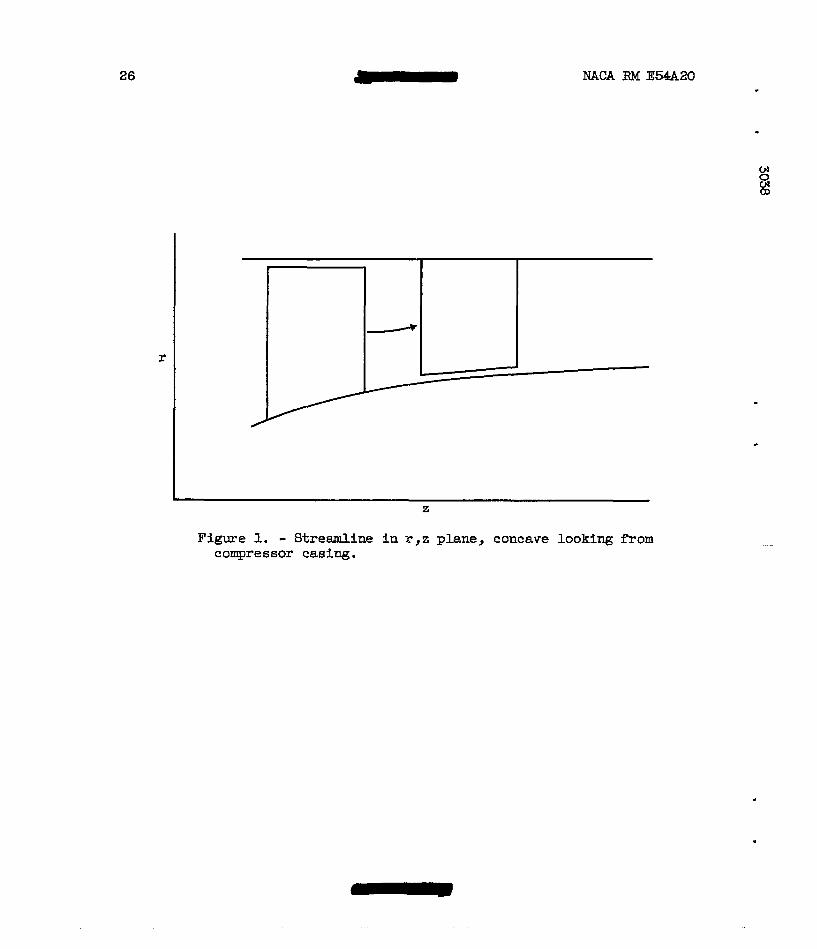
the sign of the radial-flow term is positive for streamlines concave looking from the compressor casing (fig. 1) and negative for.streamlines convex looking from the casing.
In the conventional tests of an axial-flaw compressor, the instru- mentation is not designed t o determine the radial component of the abso- l u t e velociity after the blade rows since it is assumed t o be small. lChfs- assumption is
v*2 + v,2 v2
In this presentation, the radial-flow term which was included i n ref- erence 1 Kill be neglected. A solution which uses the entropy term will be obtained and cmpared with actual data. Within the l imits of the assumptions of ax ia l symmetry and negligible viscosity at t h i s ax ia l station, the difference between th i s solution and actual data may be at t r ibuted t o the effect of neglecting the radial-flow term. A solution will also be obtained i n which both the entrapy term and the radial-flow term are neglected. The ddfference between this last solution (the simplified-radial-equilibrium approxtm.tion) a& data may be at t r ibuted both t o effects of radial. entropy varfation and the radial-flaw t e r m , again with the assumption that deviations from axial symmetry and neg- l ig ib le v i scos i ty do not mask these effects. Consequently, a compazison of these two types of analytical solutions with compressor data may in- dicate the re la t ive magnitude of the effect of radial entropy gradient and radial-flow term an the radial variations of the f lu id state.
The type of flow distribution (radial variation of whirl) and the compressor geometry determine the importance of the radid-flow term. For free-vortex flow, little radial shift of streamlines occurs through blade rows so the radial-flow term is probably unbportant. The radial pressure gradients attendant to wheel-type o r wheel-minus-vortex (symmet- r i c a l velocity diagram) distributfons of w h i r l cause radhl flaws and appreciable curvature of the streamlines. This effect is discussed i n reference 12 and tends to make the radial-flow term more important. The geometric characterist ics of law hub-tip radius ratio, high hub curvature, and high aspect ratio tend t o increase the inrpartance of the radial-flow term.
ANALYSIS OF EXPERIMENTAL DA!3!A
Application of Radial-Equilibrium Equation
Ln order t o compare expelmental data w i t h the solutions based on - simplified radial equilibrium including an entropy gradient and solutions based on simplified-radial-equilibrium approximation, equation 3( a) must

10 - NACA RM E54A20
be solved and written in a form su i ted to convenient application to the data. By making several simplifying 88sumption~, a ueeful numerical solution of equation (3s) can be obtained.
When equation (3a) is integrated between a radius at which a l l the dependent variables are known or assumed (subscript k) and a radius at which 8ome of the dependent variables are unknown (subscript u), a rearrangement (the radial-flow term is dropped) gives
It is desirable for canrparing analytical results with actual data t o put equation (9) in to a farm involving only absolute velocity, absolute a i r angle, total pressure, and t o t a l temperatme after the blade row. This expression can be developed as follows:
By using equation (8) and the steady-flow energy equation
equation (9) can
(2RT -
A numerical
t =
be written as 'IC
dr + Vk2 + 2 L u 9 r dr + 2cp(Tu - Tk)
solution of equation (ll) far Vu may be obtained i f the following simplifying assumptions are made in order t o f a c i l i t a t e integration of equation (ILL 1 :
(1) Ve2/r varriee l inear ly between the two radif of integration.
( 2 ) T varies linearly between the two radii of integration.
(3) V2 varies l inearly between the two radii of integration.
(4) s/R varies l inear ly between the two radii of integration.
These four assungtione m e nearly correct if the radial positions are close together. After the flow problem has been solved, the abwe
.
.

NACA RM E 5 W 0 a
integrands can be plotted against the variable of integrat ion to check these assumptions of l i n w i t y , and corrections can be made 9f necessary util equation (U) is sat isf ied.
-
With the use of the assumption of lineax variation of T and V2 between the radii of integration, the f l rs t integral on the right side of equation (U) may be evaluated by the trapezoidal rule as follaws:
The entropy a t a fixed radial positibn at axid sta t ion 2, fo r example, may be expressed (from eq. (5)) as
L - where sref is the entropy of the gas at some reference point upstream. For the data presented herein, the reference point is the depreseion tank and sref = so. Therefore, at axial s ta t ion 2 the quantity
The t h i r d term on the right side of equation (ll) i s also eval- uated by the trapezoidal rule, and with the r o t i o n Ve = V sin l3 this term can be written
After the integrals have been mahated in equation (U), the re- sult ing form may be solved for v,,:

Equation (12) gives the solution for simplified radial. equilibrium including an entropy gradient. A solution for the simplified-radial- equilibrium approximation is obtained by keeping the entropy constant radially - (i.e., the term sk/R - +/R equal to zero) in equation (12). It should be noted that cp and R must have units of (ft-lb)/(slug) (%) in this derivation-
Solution of Velocity Distributions 3 The solution for velocity at all radii based on simplified radial
M
equilibrium including entropy gradient requires a knowledge of the radial. variations of total pressure, total temperature, and absolute air angle after the blade row, and the inlet conditions to the compressor. With the aid of the absolute measured velocity at or near the mean radius aB the initial Vk, solutions of equation (12) for Vu for the radial position on either side of the mean radius can be obtained. These values of Vu are then taken ae vk f o r the solution of velocity at the next radial position nearer the hub asd tip. When this first velocity distribution has been calculated across the passage, the weight flow is computed by using the relation
when the static density is given by
The value of weight flow obtained from equation (13) fs cornpaxed with the weight flow calculated from the radial-survey data, and the initial value of Vk at the mean radius is corrected by the ratio of these weight flows to give a second value of Vk at the mean radius for the second approximation. This process is repeated until continuity is satisried a s evidenced by the agreement of the actual and computed weight I lows .
The same procedure is used to compute the values of Vu from the simplified-radial-equilibrium approximation. As stated previously in the section Application of Radial-EquSlibrium Equation, the term ( sk - su)/R is set equal to zero in equation (121, which then reduces to the simplified-radial-equilibrium approximation.
4.

NACA FUN E54,A20 I
Interpretation of Data
13
Comparisons were-made among the measured and two types of computed velocit ies f o r the portion of the flow outside the bm-y layer after guide vases, rotors, and stators for a var ie ty of compressor configura- t ions. The blade rows involved cover a wide range of aspect r a t i o and
0 4 . w 0 hub-tip radius ratio. The c0rqPa;rison also covers a range of operating Q, conditions for the blade row so that the effect of varying losses upon
the re la t ive magnitude of the terms of the equilibrium equation may be investigated. Ih this presentation the discussion is divided i n t o two sections.
The f i r s t section presents results for stages uith uniform entropy at the in le t ( s ing le stages and i n l e t stages of multistage compressors); the second section presents results for stages with an inlet entropy gradient (middle and end stages of a multistage unit) This division i s made because it i s expected that the ef fec t of the entropy gradient will be markedly greater for stages with an inlet entropy gradient than for stages w i t h uniform i n l e t entropy. These sections are subdivided- fo r convenience into subsections for comparisons of veloci t ies after rotors and stators . Most of these measurements were taken in the free-stream region out of the end-wd boundary layers. However, a limited amount of boundaxy-layer data was obtained and is discussed i n a fur ther sub- division enti t led rrBoundary-layer data" of the section on inlet stages. A large number of calculations w e r e made for each configuration, but only representativg results are presented i n th i s report .
In order t o clarify the method of cornpazing velocit ies, figure 2 shows the effect of adding the entropy-gradient term to the simplified- radial-equilibrium approximations. It can be seen, in f igure 2(b) for instance, that.using the loss term not only reduces the veloci t ies a t certain radii but also shifts the prof i le ver t ica l ly to sa t i s fy con- t inu i ty . The effects of loss profile with minhum losses at points other than the hub, mean, or t i p radius could be similsrly analyzed.
After the solution with simplified radial equilibrium including an entropy gradient for veloci t ies is obtained, it may s t i l l differ from measured velocit ies. . This discrepancy can be a t t r i bu ted t o the neglect of the radid-flow term if the deviation from axid symmetry as w e l l e.6 the viscous action at the axial s ta t ion in question are assumed negligible. Figure 3 shows the interpretation of comparison of the measured veloci t ies with velocities computed from simplified radial equilibrium with losses. The shape of the streamline i n the r,z surface required to correct a solution for simplified radfal equilibrium including an entropy gradient t o coincide w i t h measured veloci t ies can be ascertained from such comparisons. 7 :
I
NACA RM E54A20 14
Single Stages
Downstream of guide vanes. - .Axial-velocity ratios for the axial s ta t ion downstream of the guide vines calculated from measured data and from the solution far simplified r.adial equilibrium are presented i n fig- we6 4 t o 8. Axial-velocity ratios calculated from the solution for simplified radial equilibrium including the entropy gradient are pre- sented i n figure 4 as an example of the effect of the radial variation of guide-vane losses on the axial-velocity profile damstream of a s e t of circular-arc sheet-metal guid.e vanes.
Low hub-tip ratio stages: - The dimensionless axial-velocity pro- f i les presented i n figures 4 t o 7 were obtained from compressors of low rotor-inlet hub-tip ratio (0.50 t o 0.55). These configurations were also similar i n flow dist r ibut ion as w e l l as i n geometry: They were designed fo r wheel-type or wheel-minus-vortex rotor-inlet whirl.
A compmison between the axial-velocity profiles obtained from data and those from the solution for 's implified radial equilibrium presented in f igures 4 t o 7 reveals the sane t rend for most cases: The solution yields axial velocit ies which are lower near the t i p and higher near the hub than those calculated from data. The only exception t o t h i s trend (f ig . 4( c) ) represents operation at a low-flow coef'f ic ient . As dis- cussed in reference 13, rotor operation at low-flow coefficients can r e s u l t i n a recirculating type of flow at the rotor t ip . The possible consequences of t h i s type of flow will be brought out Fn connection with the streamline-curvature and entropy-gradient characteristics.
The axial-velocity profiles obtained from the solution including the entropy gradient are s l ight ly different from those obtained from the simplified-radial-equilibrium solution. The effect of the entropy gra- dient, for the two cases presented, is t o increase slightly the discrep- ancies at the hub and t i p between the axial-velocity ratios obtained from data and those obtained by simplified-radial-equilibrhm calculation. (Because t h i s effect w a s small, and because the available guide-vane-loss data for other configurations indicated approximately the same loss char- acteristics, the solution including the entropy gradient was not deter- mined for the data of f igs . 5 t o 7.) For the low-flow case (fig. 4 ( c ) ) , the recirculating flow at the r o t o r t i p would increase the entropy up- stream of the rotor and thereby lower the in le t axial velocity.
The discrepancies between the axfal-velocity profiles obtained from data and from the solution for simplified radial equilibrium me probably a consequence both of the assumption of axial symmetry and the neglect of the radial-flow term. The analysis of reference 1 4 shows tha t , fo r guide vanes with a radial cfrculation gradient, the condition of irro- tationali ty requires that a tangential gradient of radial velocity m e t exis t . The radid component of N e r * s equation for steady flow ex- pressed in cylindrical coordinates i s as follows:

NACARME54AZO . - 15
w
a3 E3
.
Frm equation 15, It can be seen that for such a flow the assumption ve2 bVr avr that 1 9 = - 1s not exact even - = - = 0.
p d r r d r dz
If the trend indicated in f i w e s 4 t o 7 can be partly attributed. t o the effect of streamline curvatue, t h i s curvature must necessarily be concave with respect to the casing (fig. 3). Because of the type of whirl addition through the guide vanes (wheel or wheel-minus-vortex), the result ing radial pressure gradient tends to force the flow towards the hub as it passes through the guide vanes. As the gas passes from the guide vanes t o the rotor , the hub taper causes a curvature of the streamlines (aVr/az # 0). It is probable, therefore, that a t t he axial location of the measuring stations this curvature is concave with respect t o the casing (fig . l), except immeaiately adjacent t o the hub; and the trend of figures 4 t o 7 is therefore a logical one. For the case of low- flow operation (fig. 4(c)), recirculating flow at the ro to r t i p w o u l d increase the specific mas8 flow ne= the rotor hub in proportion t o the mean-radius and tip-region mass flow. !Phis ef fec t would decrease the concavity of the streamline and explain the better agreement between calculated and measured axial velocities near the hub.
H i g h hub-tip ratio stages : - The data of f igure 8 were obtained from a single-stage compressor w i t h a hub-tip r a t i o of 0.8 and desieped fo r the addftion of wheel-type whirl through the guide vales. In contrast wlth the trend of figures 4 t o 7, the axial-velocity ratios calculated from the solution for simplified radial equilibrium are sl ightly lower near the hub and higher near the t i p than the data. EP the solution for simplified radial equilibrium including the entropy gradient had been obtained (the necessary guide-vane-loss data fo r such a solution were not available), the calculated axlal-velocity ratios probably would have more closely agreed with the data. The indication i e that the net effect of the first three terms of equation (15) is negligible. The hub taper is s l igh t fo r a hub-tip r a t i o of 0.8 and the guide-vane aspect ra t io is low (0.80) 3 therefore, the streamline curvature w o u l d be smal le r than for the campressor with a hub-tip r a t i o of 0.5. For this configuration the type of flow dis t r ibut ion has l i t t l e effect on the Smportance of the radlal-flow term, probably because the small passage depth permits l i t t l e deviation f r o m a two-dimensional f l o w .
Downstream of rotor. - Axial-velocity ratios f o r the ax ia l s ta t ion downstream of the ro tor obtained from data and from the two solutions of shrpl i f ied r a d equilibrium are presented i n figures 9 t o 17.
16 mACA RM E4A20
Low hub-tip ratio stages: - The data of figures 9 t o 13 were ob- tained from stages having a rotor-inlet hub-tip ratio of 0.55 or less. The design-flow distributions were similar: heel- type or wheel-minus- vortex rotor-inlet w h f r l with constant-enthalpy addLtion through the rotor. The comparisons between axial-velocity- prof i l ee obtained from data and from the solution for simplified radial equilibrium indicate a similar trend for each compressor i n full-stage configuration, namely, that the calculated values are s l ight ly low near the t i p and higher near the hub than the data. However, for the configurations without stators (figs. 1 2 and 13) good agreement i s indicated between measured and cal- culated axial-velocity profiles. The curves of f igure 9 .Indicate that vaziation of flow coefficient has l i t t l e e f f e c t on the observed trend that the calculated velocit ies exceed the data near the hub. The solu- t ion for simplified radial equflibrium including the entropy gradient ( f igs . 9 t o 13) is not markedly different from the solution without the entropy gradient.
The trends of figures 9 t o ll are similar t o those observed for the data sfter the guide vanes, and a similar analysis can be applied. As discussed i n reference 12, the radial pressure gradient downstream of a rotor w i t h wheel-minus-vortex inlet flow causes a radial flow towaxd the hub; af ter the stators the flow shifts toward the casing. The bloc-e effect of the s ta tors ( the fact that they block more of the annular-flow area near the hub than near the casing) also contributes to this s h i f t i n flow. Geometrically, the large passage depth and high rotor-blade aspect ratio (2.7 to 3.0) contribute t o an appreciable curvature of the streamlines. All these effects tend to make the streamlines concave looking from the casing at the measuring s ta t ion downstream of the rotor. The velocity comparisons of figures 9 t o ll indicate that the streamliner are concave i n these instances. The term of N e r ' s equation (ea. 15) neglected becauee of the assumption of axia l symmetry might also be s i g - nificant. The accumulated guide-vane and rotor losses were insufficient t o cause, through the entropy gradient, a marked effect on the axial- velocity profiles for the free-stream region.
The trend indicated in figures 1 2 and 13 of better agreement between calculated and measured axid velocities than is indicated for the sene rotors in f igures 9 and 10 can probably be explained by the absence of s ta tors . Without stators there is less tendency for a shift i n flow damstream of measuring s ta t ion 2, and the flow probably s tabi l izes on approximately conical surfaces.
High hub-tip ratio stages: - The configurations from which the data of figures 14 t o 1 7 w e r e obtained have rotor-inlet hub-tip ra t ios of 0.80 and higher, The most interesting trend is the good agreement between data and the solution for simplified radial equilibrium including the entropy gradient. As w a s the case for data upstream of the rotor, the indication is that the net effect of streamline curvature and axially

NACA €Ed E5420 17
w w 0 0)
asymmetric flow is negligible. Also, the effect of losses is more appre- ciable than for the low hub-tip ratio stages, probably because the high hub-tip r a t i o units operated at higher blade loadings, with consequently higher total-pressure losses, and because the blade-end region consti- tuted a greater proportion of the passage height.
Downstream of s ta tors . - Axial-velocity profiles for low hub-tip r a t i o stages at the measuring s ta t ion downstream of the s ta tors are presented i n figures 18 t o 20. The curves indicate good agreement be- tween data and the calculation including entropy gradient. The entropy gradient was especially significant at low flm (figs. 18(b) and 19(b)) . A negligible effect of axial ly asymmetric flaw and radial flaw is in- dicated. The s h i f t i n flow towards the casing which occurs through a stator-blade row is augmented by the hub taper. As the flow proceeds downstream from the statms, it tends t o s tab i l ize on approximately coni- c a l surfaces ( i f no r o t o r follows ] or is sh i f t& back toward the hub through the following rotor. The analysis of reference 1 2 indicates that the stream surfaces through a second stage are simjhr i n shape t o the hub contour. Thus, the streamline curvature wou ld be small with a neg-
” l ig ib le e f fec t on the computed axial-velocity profile.
Boundary-layer data. - Supplementazy flow measurements w e r e made at radial stat ions c lose to the hub and casing and are compared with ana- l y t i c a l Solutions in figures 2 1 to 23. Figure 2 1 shows velocity com- par i sons after a rotor w i t h a high hub-tip radius r a t i o where the veloci- ties obtained by u s i n g simplified radial equilibrium with an entropy gradient agree with measured velocit ies. The simplified-radial- equilibrium approximation gives velocitlee which axe high i n the casing boundary layer (the region where the a x l a l velocity drops sharply).
A comparison of velocit ies after a transonic rotor with low hub-tip radius ra t io is sham in figure 22. The solution for velocit ies which does h o t include an entropy gradient shows again the pattern of veloci- t i e s which me too high i n the t ip regions. These analytical. velocities, which are too low a t most radial stations ne= the hub, are higher at the radial station nearest the hub thes the measured velocit ies and velocities obtained analyticaJly by using an entropy gradient. The comparison of velocities indicates that the entropy rises shasply in the boundary-layer regions, while in the main-stream region the minimum en- tropy occurs ne= the hub and rises gradually t m d the t i p .
For the available boundary-layer b t a after s ta tors ( f ig . 231, the measured veloci t ies and the velocities calculated by using simple rad ia l equilibrium including an entropy gradient agree very closely. Analytical velocit ies obtained by the simple-radial-equilibrium approximation are markedly high ne= the hub and t i p and low near the mean-radius sta- tion; they are more incorrect than the velocities obtained by this type of calculation after the rotor of f igure 22.
c

18 NACA RM E54A20
In general, the close agreement between measured velocit ies and velocities calculated by using simplified radial equilibrium with an entropy gradient sham i n figures 21 t o 23 indicates the radial-flow term is unimportant here. 'For the configuration of figure 21, the high hub-tip radius ratio prevents any large deviations from two-dimensional flow; for the low hub-tip radius ratio stage of figures 2 1 and 22 there is l i t t l e tendency f o r radial flows because of the flow distribution ( zero rotor- met whirl 1.
The effect of the entropy gradient outside the boundary layer is greater for the transonic rotor (fig . 22 ) than for the subsonic inlet- stage cmpressors ( f i g s . 9 t o =). The transonic rotor has a m e r re la t ive inlet hch number and also R larrger radial variation of rela- t i ve inlet Msch number than the subsonic stages, leading t o larger total-pressure losses and l a g e r ' radial variations i n total-pressure losses in the transonic stage. The magnitude of the diecrepancy between the two radial-equilibrium solutions is higher aSter stator than after rotor because of additional losses incurred by the stator-blade row.
The inpor tace of estimating blade-eiement and boundary-layer losses in design calculations is emphasized by the large discrepancies between the two analytical velocities. The close agreement between data and cal- culations including an entropy gradient in the boundary-lapr regions indicates that the blockage effect of the boundary layer can be taken into account by a design asmmrption of the boundary-layer stagnation- pressure profile. This ~ ~ s u m e d profi le can be based on available boundmy-layer-loss data.
Middle ana En3 Stages of Multistage Canpressor
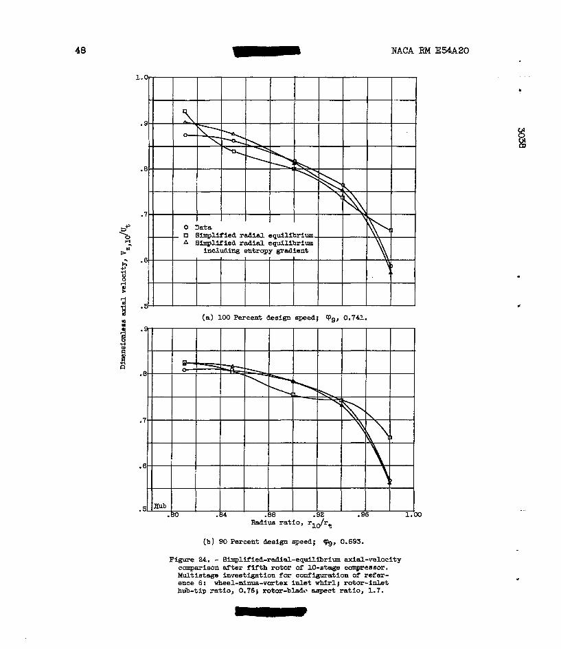
Downstream of rotors. - The configurations in this sect ion differ from those previously discussed in that the entropy gradient is higher since losses have accumulated for several stages. Figure 24 shows data from a rotor which is preceded by four stages of a multistage compressor. Comgarisons are made i n t h i s case fo r a range of flow coefficients t o ascertain the e f fec t af a wide vwiety of losses through a specified blade row on the trends of the solutions based on sinzplified radial equilibrium with an entropy gradient. In all caBes, including the en- tropy gradient i n the simplified rad= equilibrium, calculations led t o good agreement with messwed velocit ies. Mmilwly, investigations for a large rimer of flow coefficients were made f o r the other configura- tions in t h i s section and shared again that the entropy-gradient correc- t i o n l e d t o good agreement w i t h measured velocities. Since these com- parisons for a variety of flow coefficients are similar t o those of figure 24, they are not included in the figures presented.

NACA RM E54A20 - 19
Velocities after the last rotor of a 10-stage compressor are sham in f i gu re 25. N e a r design conditions after these rotors (figs. 24(a), 24(b), and 25(a)) the simplified-radlal-equilibrium approximation gives velocit ies which are high for both hub a d t i p s t a t ions and low ne= the mean radius station, indicating that the shape of the entropy gradient is different from those found in the single-stage compazisons. As pointed out i n figure 2(b), the entropy has a rninfmum value at sane intermediate radius between hub and t ip , showing that the losses a r e greatest near the end walls. The growth in l o s ses near the hub for the middle-stage rotors i a the most significant change frcm the loss profiles indicated for the single-stage configurations. These changed profiles mey result from the accumulation of losses which occur at the unattached blade ends, on the end w a l l s , or on the blades. Figures 24(c) and (dl show exceptions t o this pat tern, for here indications Etre that the entropy increases f rom hub t o t i p . These are low-flaw-coefficient runs at which the blades might be expected t o operate inefficiently, w i t h the t f p region being most sensit ive to changes i n weight f l o w . As the flow coefficient is decreased (figs. 24(c) and (a)), the losses at the t i p regions became
-
4 8
3 highest, changing the entropy gradient pronauncedly. 3 F Downstream of stators. - The inadequacy of simplified-radial-
& V and 27. Data after the f i f th and ninth stators of a multistage com-
n equilibrium approximation after stators is shown c l ea r ly i n figures 26
pressor show that the consideration of the entropy term is even more important here than after the rotors. The simplified-radial-equilibrium- approximation solutions give very poor agreement with actual data. After the f i f t h s t a t o r the entropy reaches a pronounced maximum i n the end regions of the blade, as indicated by figures 26(a) and (b) - N e a r design conditions after the ninth s ta tor (fig. 27(a)) the same type of entropy gradient as for the fifth s ta tor (fig. 26) is indicated. A t off-design conditions (fig. 27(b)) as increase in losses near the casing which occurrs after the rotors is also apparent aft- these s ta tors .
Discussion of multistage results. - The radial-entropy variation in the latter stages of a multistage campressor m u s t be evaluated and used i n the equilibrium equation Fn order to cor rec t ly compute axial-velocity profiles . This variation follows a general pattern; at or near design weight flow the entropy has a minimum value near the mean radius, in- creasing toward each of the end walls, while at f l o w coefficients other than design the entropy has a minlmum at the hub region and increases monotonically toward the t t p .
Application of Radial-Equilibrium Equation
In view of the results of the experimental investigation, it would be des i rab le to use a procedure based on equation (9) i n the calculation

20 MACA RM E54A20
of velocity diagrams for the design of a multistage machine. In an axial- flow turbomachine design, the variables which will be known or assumed are the inlet conditions to the blade row, the desired weight flow, and the losses or adiabatic efficiency of each blade element. The radial gradient of energy addition is usually prescribed through an analytical variation of either Vo or AK with radius. In order to obtain the total-pressure rise from the total-temperature rise, the blade-element total-pressure losses must be known or assumed a.6 functions of the velocity-diagram parameters. For instance, the relative total-pressure- loss parameter 'E i s presented in reference 14, wherein the relative- total-pressure loss is given as a function of re la t ive inlet Mach number and a blade-loading parameter, the diffusion factor D. A preliminary solution of the simplified-radial-equilibrium approximation can be ob- tained in order t o calculate D factors, o r the diffusion factors can be assumed on the basis of previous experience. This assumed radial variation i n losses now yields an assumed radial variation in entropy, since from equation (5a)
c
- = "0 + 74 62 R R
- Tz r-l
A first approximation t o the axial-velocity T--ofile after the rotor can now be found by using equation (9 ) . By selecting a value for VZt2 at the mean radius, using t h i s as VZ,Z,h, and salving for V,,2,u at the next stations toward hub and t i p , the velocities acroas the en t i re pas- sage can be f a d by repeating the process with the results of each etep used as reference values-in t h e next step. Since the method gives accu- rate profiles ( i f blade-element-. and end-wall-loss data are available) across the passage from hub t o casing, corrections such as blockage fac- tor or boundary-layer displacement thickness are unnecessmy for the continuity equation.
Solution f o r Velocity Distributions
The design procedure will vary depending on whether the passage area or mean-axial-velocity variation I s fixed through the machine. In both case6 an iteration process w i l l be necessary and the attacks w i l l be similar. An example w i l l be made for a rotor with a fixed passage area ( rh and rt known). This is the type of calculation which might be applied after a preliminary analysis on a mean-radius basis has deter- mined the hub contour ( for a fixed-tip-radius machine). In t h i s case the following factors would be knoWn.or assumed:

W A RM E 5 W 0 2 1
(1) Hub and t i p radii throughout the machine
( 2 ) Weight flow
(3) Rotative speed
(4 ) Inlet t o t a l temperature and pressure
A convenient design method is t o prescribe the outlet radial varia- 0 co
t i on of tangential velocity (hence the energy addition in the case of a rotor) . For simplicity, the streamline flow is assumed t o occur at equal increments along the radius, thus f ixing r 2 as a function of rl. The total-temperature rise across the rotor caa now be found a t each radial position from the equation
In addi t ion to the requirement that equation (9) be satisfied after the blade row, the continuity equation (13) m u s t a l s o be satisfied at t h i s axial station. Since the variation of s t a t i c temperature w i t h radius is
generally s m a l l th = O), a first approximation may be made by \ "'m /
assuming that t = constant and is eqml to the value at rk. Equation (9 ) combined with equation (10) then yields the following equation:
This solution must be corrected t o obtain the proper weight fluw. With the use of the values of Vz,2 obtained from solutions of equation (17), the equation for continuity can be solved (by u s i n g eqs. (13) and (14)) and an integrated w e i g h t flow at s ta t ion 2 obtained. If the in- tegrated weight flow is within 2 percent of the desired fluw, a simple adjustment of a l l the velocit ies by t h e r a t i o of flows will suffice. Otherwise, the original aesumption of mean axial veloci ty must 'be ad- justed by the r a t io of flaws and equation (17) again solved. -

22 W A RM F54A20
If the axial-velocity distribution (which is combined with pre- scribed tangentid velocity distribution to give flow angles) which results from these solutions is much different fran the expected dis- tribution (causing the D factors to be dlfferent from those expected), an adjustment of the assumed blade-element losses may be in order, and a new solution obtained on this basis. This adjustment could a l s o be made as a refinement of the method after a tentative choice of blade shapes is made and the best available blade-element total-pressure-loss data are applied.
In any solution for the precise velocity distribution after a blade row, the need for blade-element- and end-region-loss information is evi- dent. This is especially true in multistage-compressor calculations where blade-element-loss accumulations may cause an appreciable radial gradient of entropy in the latter stages with resulting large effect8 on the axial-velocity distributions.
SUMMARY OF RESULTS
The investigation of the validity. of application of the simplified- radial-equilibrium equation to compressors gave the following results:
1. In order to calculate accurately the radial variation of ve- locities, it was necessary, in general, to include measured stagnation- pressure losses i n the simplified-radFal-eQuilibrium equation. The assumption of zero radial entropy gradient was invalid for the calcula- tion of velocities at axial stations more than one or two blade row8 damstream from a region of uniform entropy. At an axial station fol- lowing several stages of a multistage compressor, large discrepancies were observed between measured velocities and velocities computed by using the simplified-radial-equilibrium equation but neglecting the entropy gradient; whereas the velocities computed by using the entropy gradient agreed closely with the data.
2. Very close agreement w a s observed between data and the calcula- tions made by using an entropy gradient in the boundary-layer regions at the hub and tip; whereas the calculations which did not include the entropy gradient were not correct. This trend suggests that the blockage effect of the boundary layer can be taken into account by a design as- sumption of the boundary-layer stagnation-pressure profue based upon available boundary-layer-loss dkta.

NACA RM E54A20 23
3. Results of this investigation suggest that a velocity-diagram design method including the effect of the estimated stagnation-pressure losses on the design axial-velocity profile would give more accurate velocity diagrams than present methods which do not include stagnation- pressure losses. A velocity-diagram design method including stagmtion- pressure losses is presented i n this report.
L e w i s Flight Propulsion Laboratory National Advisory Committee for Aeronautics
Cleveland, Ohio, January 27, 1954

24 NAl;rA RM E54A20
1. Wu, Chung-Eua, and Wolfenstein, Lincoln: Application of Radial- Equilibrium Condition to Axial-Flow Compressm and Turbine Design. NACA Rep. 955, 1950. (Supersedes mAcA '1IN 1795.)
2. Mkrble, Frank E., and Michelson, Wing: Analytical Investigation of Some Three Dimensional Flow Problems in Turbo-Machines. NACA TN 2614, 1952.
3. Traupel, Walter (C. W. Smith, trans. 1: New General Theory of Multi- stage Axial Flow Turbomachines. Navships 250-455-1, Navy Dept., Washington (D. C . ) .
4 . Robbim, William H., and G l a S e r , Frederick W.: kvestigation of an Axial-Flow-Compressor Rotor with Circular-Arc Blades Operating up to a Rotor-Inlet Relative Mach EsumBer of 1.22. RACA RM E53D24, 1953.
5. Jaclcson, Robert J. : Effects on the Weight-Flow Range and Efficiency of a Typical Axial-Flow Compressor Inlet Stage that Result from the Use of a Decreased Blade Camber or Decreased Guide-Vane Turning. MACA RM E52G02, 1952.
6. Budinger, Ray E., and Serovy, George K.: kvestigation of a 10-Stage Subsonic Axial-Flow Research Ccanpressor. IV - Individual Stage Performance Chaxacteristics. NACA RM E S 3 C l l , 1953.
7. Standahar, Raymond M., and Seravy, George K.: Same Effects of Changing Solidity by Vaxying the Number of €!&des on Performance of an Axial- Flow Compressor Stage. W A RM E52A31, 1952.
8. Moses, J. J., and Serovy, G. K.: Some Effects of Blade Trailing-Edge Thickness on Performance of a Single-Stage Axial-Flow Compressar. NACA RM E5-28, 1951.
9. Mahoney, John J. , Dugan, P a u l . D., Budinger, Ray E., and Goelzer, E. Fred: Investigation of Blade-Raw Flow Distribution in Axial-Flow- Compressor Stage Consisting of Guide Vanes and Rotor-Blade Row. NACA RM E50G12, 1950.
10. Schwenk, Francis C., Lieblein, Seymour, and Lewis, George W., Jr.: Experimental Investigation-of an Axial-Flow Compressor Inlet Stage Operating at %ansonic Relative Inlet Mach Mumbers. 111 - Blade- Row Performance of Stage with 'l!rmsonfc Rotor and Subsonic Stator at Corrected Tip Speeds of.800 and 1000 Feet Per Second. NACA RM E53G17, 1953.

W A RM E 5 W 0 25
w 0 4 0 Q,
ll. Lieblein, Seymour , Schwenk, ??rancis C. , and Broderick, Robert L. : Diffusion Factor for Estimating Losses and Limiting Blade Loadings in Axial-Flow-Campressor Blade Elements. NACA RM E53D01, 1953.
12. FTU, Chung-€ha: Subsonic Flow of Air Through a Single-Stage and a Seven-Stage Compressor. NACA TN 2961, 1953.
13. Finger, Harold B., and Dugan, James F., Jr.: Analysis of Stage Matching and Off -Design Performance of Multistage Axial-Flow Compressors. HACA RM E52DO7, 1952.
14. Lieblein, Seymour, and. Ackley, R i c h a r d H. : Secondary Flows in Annular Cascades and Effects on Flow in Inlet Guide Vanes. NACA RM E51G27, 1951.
26 NACA RM E54AXI
Figure 1. - Streamline i n r , z plane, concave looking from compressor casing.

I
. . . . . . . . . . . . . . . . . - .. . . , . . . . . . . . -
CQ-4 back . . . . . . . .
3038
F
I I T r6- r/rt - r/rt --
(a) Minimum entropy at hub. (a) Minlmum entropy at meau. ( c ) Minimum entropy a6 t i p .
Figme 2. - Effect of elrtropy-gractLent term on simplifie8-ra8ial-equillbrium solut ione.

N m
I 0 Data * Simplified radial equllibrim with entropy gradient
r/rt - +t - (a) Streamlines inaicated t o be con- (b) Streamlines indlcated t o be con-
cave looking from caslng. vex looldng from casing.
Figure 3. - kt%rprfhtkm of comparison of meaeured velocities with solutions obtained by using simpllfled radial equilibrium including entropy gradient.

29
.
(a) H i g h flaw Cpl, 0.525.
(b) Peak efficiency point rpl, 0.493.
U
L
.5 .6 .7 .8 .9 1.0 R a d i u s rat io , rl/rt
(c) Low flaw T, 0.375.
Fpigure 4. - BimplFfied-radial-equilibrium axial-velocity comparison after guide vanes for single-etage om- pressor. Rotor-p1u.a-guide-vane investigation for oonflguration of refereme 4: wheel-type I n l e t whirl; rotor-Wet hub-tip ratio, 0.5; guide-vane aapect ra t io , 2.7; 100 percent design q e e d .

30 NACA RM E54A.20
Radius ratio, rdrt
Figure 5. - Sinplif ied-radial-equilibrium axial-velocity comparison atter guide vanes for single-stage com- pressor. Rotor-plus-guide-vane investigation for configuration ~f reference 5 (low-c-ered & a m ) : wheel-minus-vortex inlet whirl; rotor-inlet hub-tip ratio, 0.5; guide-vane aspect ratio, 2.9; 100 percent design speed.
.5 .6 .7 .8 .9 1.0 ~adius ratio, rJrt
Figure 6. - S~lified-radial-equilibrium axial-velocity comparison after &de vanes for single-stage com- pressor. Rotor-plue-guide-vane investigation for configuration of reference 5 (high-cambere8 &sign): wheel-minus-vortex inlet whirl; rotor-inlet hub-tip ratio, 0.5; guide-vane aspect ratio, 2.9; 100 percent design speed.

NACA RM E m 2 0 31
Q M
M 0
Radius ra t io , rl/rt
a + .6
';I a D* a + a 0
0 a)\
. 5 .80 .%4 .88 .92 .96 1.00
Figure 7 , - Simplified-radial-equilibriwn axial-velocity comparison after guide vanes fo r 10-stage compressor. Multistage- compressor investigation for configuration of reference 6: wheel-minus-vortex inlet whirl; rotor-inlet hub-tip ratio, 0.55; guide-vane aspect r a t io , 2.6; 90 percent d 0 B m Speed.
Radius ra t io , rl/rt
Figure 8. - Simplified-radial-equilibrium axial-velocity comparison after guide vanes for single-stage com- pressor. Full-stage investi@;ation f o r conf'iguration of reference 7: wheel-type inlet whirl; rotor-Inlet hdb-tip ratio, 0,8; guide-vane aspect ra t io , 0.8; 100 percent design speed.

32 NACA RM E m 2 0
(a) High flow T, 0.445. Figure 9. - Simplified-radial-equilibrium axial-velocity
comparison &ter rotor for single-stage compressor. Full-stage investigation for configuration of refer- ence 5 (high-canibered design) plus 65-series stator blades: wheel-minus-vortex inlet whirl; rotor-inlet hd-tip ratio, 0.5; rotor-blade aspect ratio, 2.7; 100 percent design speed.
..

.
NACA RM E54AZO 0
(b) Peak efficiency polnt Cpl, 0.386.
Figure 9. - Continued. S i q l i f ied-radial-equilibrium axial-velocity comparison after rotor for single-stage compressor. Full-stage investigation for configura- tion of reference 5 (high-canhered design) plus 65- ser ies s ta tor blades: wheel-mfnus-vortex in l e t w h i r l ; rotor-inlet hub-tip ratio, 0.5; rotor-blade aspect ra t io , 2.7; 100 percent design speed.
33
.o

34
Radiu6 ratio, r2/rt
( 0 ) Lon f l W Cp1, 0.288.
NACA RM E54A20
Figure 9. - Conoludd. SimpSlf ied-radial-equilibrium axial-velocity comparison after rotor for single-stage compressor. Full-stage investigation for configura- t i o n of reference 5 (high-canibered design) plus 65- series s ta to r blades: wheel-minus-vortex inlet wkirl; rotor-inlet h a - t i p ratio, 0.5; rotor-blade aspect ratio, 2.7 ; 100 percent design speed.

NACA RM E M 2 0 . 35
%
b
d e - m
V-
.7. I 1 I I t o Data n Sinplified radial equilibrium A Simplified radial equilibrium
R a d i u a ra t io , rdrt
Figure 10. - Simplified-radial-equilibrium axial-velocity comparison after rotor f o r single-stage compressor. Nl-s tage investigation for configuration of refer- ence 5 (low-cambered design) plus 65-series stator blades: wheel-minus-vortex inlet whfrl; rotor-inlet h d - t i p r a t i o , 0.5; rotor-blade a s p c t r a t i o , 2.7; 100 percent design speed.

36 NACA RM E54A20 .
. ' I 1 I t 1 0 Data 1 1 I 1
Figure ll. - Simplified-radial-equflibrium axial-velocity comparison after flrst rotor f o r 10-stage compressor. Multistage-compressor investigation for configuration of reference 6: wheel-minus-vortex inlet whirl; rotor- inlet hub-tip ratio, 0.55; rotor-blade aspect ratio, 3.0; 90 percent design speed.

NACA RM E%20 37 .
Figure 12. - S~plified-radial-equilibrium axial-velocity comparison after rotor for single-etage compressar. Rotor-plus-guide-vane investigation for configuration of reference 5 (low-cambered design): wheel-minus- vortex M e t whirl; rotor-inlet hub-tip ratio, 0.5; rotor-blade aspect ratio, 2.7; 100 percent design speed.
.
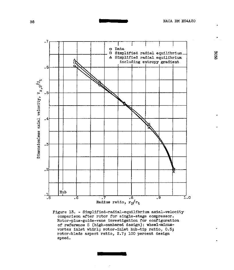
38 NACA RM E54A20
Radius ra t io , r2/rt
Figure 13. - S~lified-radial-equilibrium axial-velocity comparison after ro tor for single-stage compressor. Rotor-plus-guide-vane investigation f o r configuration of reference 5 (high-cambered deeign): wheel-minus- vortex inlet w h i r l ; rotor-inlet hub-tip ratio, 0.5; rotor-blade aspect ratio, 2.7; 100 percent design speed.

NACA €24 E54A20 L 39
.6
.5 I - I I I I I o Data n Simplified radial equilibrium A Simplified radial equilibrium
including entropy gradient .4- Hub I I I I I .80 .84 .88 .92 .96 1.00
R ~ U S r a t io , r2/rt
.
Figure 14. - Simplified-radial-equilibrium axial-velocity comparison after ro tor for single-stage compressor. Rotor investigation f o r configuration of reference 8: zero inlet w h i r l ; ro tor- inlet h ~ - t i p r a t i o , 0.8; rotor- blade aspect ratio, 0.74; 124 percent design speed,
Radius r a t io , r Z / r t
Figure 15. - Srmplified-radial-equilibrium axial-velocity comparison after rotor f o r single-stage compressor. Full-stage investigation for configuration of refer- ence 7 (high sol idi ty) : wheel-type i n l e t whirl; rotor- inlet hub-tip r a t io , 0.8; rotor-blade aspect ratio, 0.88; 100 percent design speed.

4 0 NACA RM E W 2 0
.7-
.6.
.5 I , I I I I I I
.80 .84 .88 92 96 1.00 UI
- A Simplified radial equilibrium including entropy gradient I lEub i I I I I I \
R a d i u s ra t io , r2/rt
Figure 16. - S~l i f i ed - rad ia l - equ i l ib r ium axial-velocity comparison after rotor for eingle-stage compressor. Full-stage investigation for configuration of refer- ence 7 (medim sol idi ty) : wheel-type in l e t whirl; rotor-inlet Bub-tip ra t io , 0.8; rotor-blade aspect r a t io , 0.88; 100 percent design speed.
.7
.6
o Data Simplified radial equilibrium
A S b p l i f i e d radial equilibrium including entropy gradient
Radius ra t io , rdrt
.5 Hub, I I . eo .84 .8a .92 .96 1-00 I I I
Figure 17. - Simplified-radial-equilibrium axial-velocity comparison after rotor for single-stage compressor. Full-stage investigation for configuration of refer- ence 7 (low sol id i ty) : xheel-type inlet whirl ; rotor- inlet hub-tip ratio, 0.8; rotor-blade aspect ratio, 0.88; 100 percent design speed.

NACA RM E54A2O - 41
Radius ratio, r h t
(b) Low flow CP,, 0.253.
Figure 18. - Simplified-radial-equilibrium arial-velocity comparison after stator for single-stage ocrmgressor. Full-stage Investigation for configuration of refer- ence 5 (low-cambered design) p l w 65-seriee sta- blades: wheel-minus-vortex rotor-inlet whirl; rotor- inlet hub-tip ratio, 0.5; etator-blade aspeat ratio, 2.5; 100 percent design speed.

42 NACA RM E54A20
.
(b) Lar flow (s, 0.288. Figure 19. - Simplified-radial-equilibrium exial-velocity
comparison after stator far single-stage compreesor. Nl-stage Investigation for configuration of refer- ence 5: wheel-minus-vortex Inlet whirl; rotor-inlet hub-tip ratio, 0.5; stator-blade aspect ratio, 2.51 100 percent design speed.
c

NACA RM E54AZO 43
% d 9
c m m
3 0 d i d
R
-r
"
"
"
"
"
6-
-
- Hub I I I . I
9 1.0 R a d i u s ra t io , rdrt
gradient I f I
Figure 20. - Simplified-radial-equilibrium axial- velocity comparison after first s ta tor of 10- stage compressor. Multistage-compressor investigation for configuration of reference 6 : wheel-minus-vortex in l e t whirl; rotor-inlet hub-tip ratio, 0.55; stator-blade aspect ratio, 2.8; 100 percent design speed.

44 - NACA RM ES4A20
(a) 100 Percent design speed.
tl Simplified radial equilibrium A Simplified radial equilibrium
1 n
.5- Hub .80 .84 .88 .92 .96 1.
Radius r a t io , r2/rt
(b) 60 Percent design speed.
Figure 21. - S ~ l i f i e d - r a d i a l - e ~ ~ l ~ b r l ~ axial-velocity coml;arison after rotor for single-stage compressor. Boundary-layer investigation f o r configuration of ref - erence 9 for rotor plus guide vanes: wheel-tne inlet whirl; rotor-inlet hub-tip r a t i o , 0.8; rotor-blade aspect ratio, 1.1.
(a) 100 Percent design speed.
tl Simplified radial equilibrium A Simplified radial equilibrium
.80 .84 .88 .92 .96 1. Radius r a t io , r2/rt
K)
e

45
.3 I a (a) H i g h flow (pl, 0.481; 100 percent m m design speed.
(b) Peak efficiency point 3, 0.460; LOO percent design flow.
Figure 22. - S~l i f ied- rad ia l -equi l ibr~um axial- velocity comparison a f t e r rotor f o r slngle- stage transonic compressor. Boundary-layer investigation for configuration of reference 10 for rotor plus stators: zero M e t whirl; ro to r - in l e t ha - t ip r a t io , 0.53; rotor-blade aapect ratio, 1.3.

46 NACA RM E54A20
I 0 Data t \ \ I 0 Simplifled radial
A Simplified radial equilibrium
equilibrium including entropy gradient
Eub 8 .7 .8 .9 1.0
Radiue ra t io , rZ/rt
(c ) Low flow cpl, 0.484; 60 percent design speed.
Figure 22. - Concluded. SfI1Iplified-radial- equilibrium axial-velocity comparison a9ter ro tor for single-stage transonic compressor. Boundary-layer investigation fo r configura- t i on of reference 10 for rotor plus stators: zero inlet whirl; rotor-inlet hu3-tip ratio, 0.53; rotor-blade aspect ratio, 1.3.

W C A RM E54A20
x x
R a d i u s ratio, r3/rt
(b) Peak efficiency p o h t ql, 0.460.
Figure 23. - Simplified-radial-elibri~ axial- velocity camparison after atetors for s ing le - stage compressor. Boundar'y-layer bvestigatioa
plus stators: rotor-irilet hub-tip ratio, 0.53; for configuration of reference 10 for rotor
&alga speed. stator-blade aspect ratio, 1.2; 100 percent
47
48 - NACA
(a) 100 Percent Uealgn s p e e d ; (Pg, 0.741.
(b) 90 Percebt design speed; ‘Pg, 0.693. Figure 24. - Bimplified-radial-equilibrium axial-veloclty
comparison after flfth rotor of 10-stage compressor. Multiatsge investigation far configuration of refer- ence 6: uheel-minus-vartex inlet W r l ; rotor-idlet hub-tip ratio, 0 .76 ) rotor-bMr* a p c t ratio, 1.7.
RM E a 2 0

.
I ..
Figure 24. - Concluded. Simpl~isd-raBial-eqWbrim axial- v e l o c i t y -iaon after f i f t h r o t o r oi lO-stag8 compree- -. Wtistage investigation for configuration of refer- ence 6: wheel-minus-vortex inlet whirl; rotor-idlct hub-tip ratio, 0.76; ro tor -bhy aspect ratio, 1.7.
49

50 NACA RM E54A20
0 Data SFmIjlif ied radial equilibrium Simplified radial equilibrium
including entropy gradient
1 . 2
1.1
1.0 Hub
(a) 100 Percent design speed.
1.6
1.5 .92 .96 1.00
Radius ratio, r20/rt
(b) 50 Percent design speed.
Figure 25. - ' Simplif ied-radial- equillbriun; axial-velocity coxnparison after tenth ro to r of 10-stage com- pressor. Multistage investigation for configuration of reference 6: wheel-minus-vortex inlet whirl; rotor-inlet hub-tip ratio, 0.91; rotor-blade aspect ratio, 0.82.
"
. .
t

NACA RM E54A20 - 51
.9
D Simplified radial equilibrium * Simplified radial equilibrium
.a
.7
I I I I I I I I I T I . U
(a) Peak efficiency point '?,, 0.689.
Radius ra t io , rll/rt
Figure 26. - Simplified-radi81-equllibrium axial-velocity capar i son a f t e r f i f t h stator of 10-stage carqpreesor. Multistage investigation for configuration of refer- ence 6: wheel-minus-vortex inlet whirl; r o t a - i n l e t hub-tip ra t io , 0.76; stator-blade aspect ratio, 1.6; 100 percent design speed.

52 - NACA RM E54A20
d- (a) 100 Percent design speed.
'1 1.
0 Data 0 Simplified radial
equilibrium A Simplified radial
equilibrium including entropy gradient
Radius ratio, r19/rt
(b) 50 Percent design sped.
Figure 27. - Shplified-radial- equilibrium axial-velocity comparison a f t e r ninth atator of 10-stage com- pressor. Multistage investigation f o r configuration of reference 6 : wheel-type inlet-whirl; rotor-inlet hub-tip ratio, 0.89; etator-blade aspect ratio, 0.87.
