research of seismic testing and dynamic character … vol6 no8_part8.pdfresearch of seismic testing...
TRANSCRIPT
Research of Seismic Testing and Dynamic Character of High-rise Building Structure Based on ANSYS
Jing Ji, Wenfu Zhang, Wenyan Zhao, Chaoqing Yuan, Yingchun Liu
College of Civil and Architecture Engineering, Northeast Petroleum University, China Heilongjiang Key Laboratory of Disaster Prevention, Mitigation and Protection Engineering,
Daqing, China, [email protected]
Abstract With the rapid development of high-rise buildings, many of the architectural buildings were this
kind of form for the bottom the podium and upper towers. The emergence of these complex architectural forms has brought many new problems to the seismic analysis of structures and seismic design. This paper describes the building seismic theory on a trial basis, using the ANSYS general purpose finite element software for seismic analysis of the tall building structures. Then we build the actual finite element model to simplify the steel structure concrete columns, and the analysis structure of the static condition. According to second phase of the seismic design, the first phase of multi-elastic was analyzed on earthquake effect of the structure. The dynamic characteristics of the entire structure were determined with modal analysis. The main three incentive direction and modal order analysis as a dynamic basis were identified. Meanwhile, the response spectrum was analyzed to determine the dynamic response of structures under seismic action, to draw the maximum internal force of the structure of each component, and these can provide the basis for the structural design.
Keywords: High-rise buildings, Seismic loading, ANSYS, Reversing reaction
1. Introduction
The generation of an earthquake is a sudden release of energy accumulated by the Earth's interior sports or crust holes roof collapse and other reasons, so that the rock severe vibration was transmitted to the surface, and the form of waves was caused by the ground bumps and jolts. Role in the mechanism of dynamic loaded on the structural system is a wide range from a structural design perspective. The earthquake is the most important form of dynamic load. A strong earthquake within a few minutes to a few seconds can make the human life and property suffered huge losses. According to statistics, there are about 5 million earthquakes in every year, but the vast majorities of people do not feel small earthquakes. With the continuous development of tall buildings, high-rise building structural analysis methods affect the quality of the building directly. Security and functionality is a noteworthy and important problem. Structure analysis method has also gone through a simple to complex, from the hand count to the computer simulation of a process. From 50-70 in the late 20th century, high-rise buildings is a relatively simple structure size. High-rise building structure analysis method was basically hand-counted because of the limitations of computer technology. Frame structure system, shear wall structure and frame-shear wall system constituted the main structure, and calculation methods have targeted. For example, there is the frame structure system with the moment distribution method, hierarchical method, and the inflection point method. In the late 1970s and early 1980s, the efficiency of the analysis of high-rise building structure was improving.
The high-rise building space collaborative work analysis has been widely used design units at all levels almost all use of such procedures, which the rapid development of China's high-rise buildings in the 1980s made a significant contribution. There have been many new high-rise building structural system in 1980s, such as the box is a tube, cut a tube, tube in tube and group barrel and other structural systems. By means of the increasing complexity of the plane and the body of the sub-high-rise buildings, the space collaborative work analysis has been unable to apply. Thus the developments of spatial analysis were promoted, for example, three-dimensional rod analysis. The method to high-rise building structure as the space bar system, direct displacement method to analyze the concept is clear, and the method is simple and adaptable [1-3, 10-11].
2. The development of seismic experiment techniques
Research of Seismic Testing and Dynamic Character of High-rise Building Structure Based on ANSYS Jing Ji, Wenfu Zhang, Wenyan Zhao, Chaoqing Yuan, Yingchun Liu
International Journal of Digital Content Technology and its Applications(JDCTA) Volume6,Number8,May 2012 doi:10.4156/jdcta.vol6.issue8.8
63
2.1. Static experimental stage
Seismic static theory was founded in the 1920s to 1940s, first proposed by Professor Omori, which is to assume that the structure is absolutely rigid body by the earthquake. It is in the horizontal vibration state. Therefore, any instantaneous structure of the acceleration of each point are equal, the inertia force on the structure of distribution and mass distribution is proportional to the structures subject to seismic force equal to the seismic loading multiplied by a seismic coefficient. Static theory ignored the actual structure of the elastic properties of the dynamic characteristics of the calculation is simple, but does not match with the actual situation.
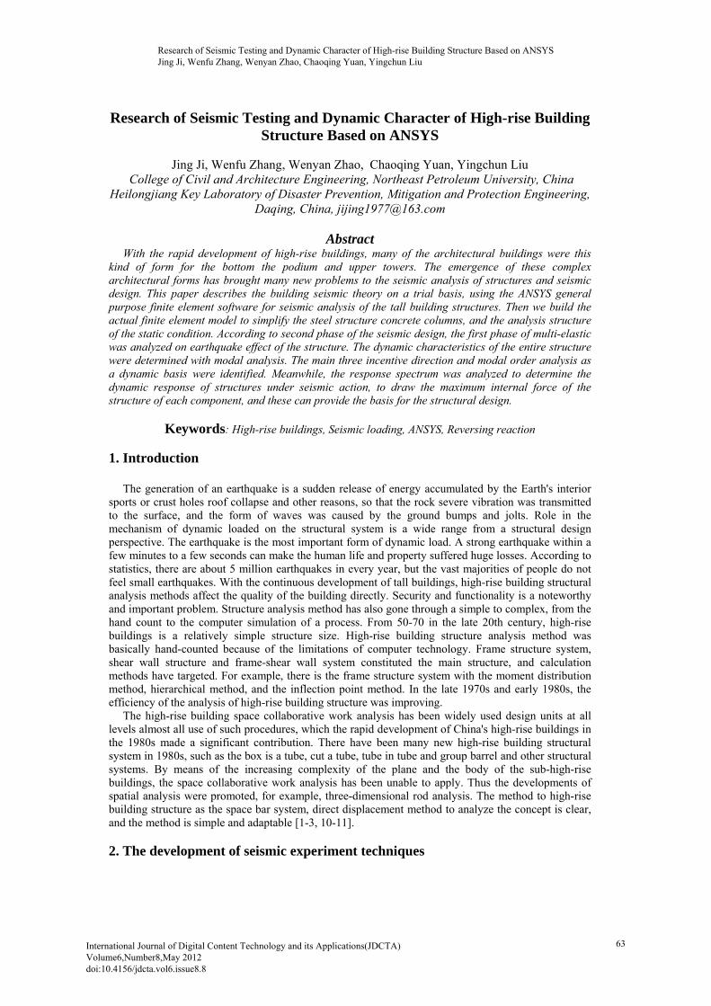
Figure 1. Contents of structural seismic analysis considering earthquake actions in two directions
2.2. Quasi-dynamic experimental stage
In 1940s, there was the response spectrum theory. It will be the seismic waves in the single-particle system, taking the displacement, the relationship between speed and maximum acceleration response of single-particle vibration system cycle. The response spectrum theory was considering the elastic properties of the structure, the modal superposition method, the use of structural dynamics and structural transformation into the superposition of the single-particle system.
2.3. Direct driving force of the experimental stage
The U.S. government started strong motion observation in 1933, and made a lot of ground motion records and seismic response of structure records. Only the discrete numerical integration method for solving the seismic response of structure of each moment, the calculation of the workload is very large, which only the computer to complete this work. The input structure earthquake response was analyzed in order to fully consider the impact of the earthquake three elements (amplitude, spectrum and duration) of structural damage, which due to the direct use of the actual earthquake records [4, 5]. The elastic-plastic nature of the structure and components was using the more reasonable of the whole process of recovery curve model. So that the calculation results can be detailed this was giving the whole process of structural seismic response. The components of the stress state in the entire process of earthquake were understood in order to determine the structures of the yield mechanism which the structures of the weak links are of great significance.
2.4. Earthquake experiments widely used stage
Beginning in the 1980s, structural seismic experiment is more active than ever. The full-scale seven-story reinforced concrete structure of a series of experimental studies in the United States and Japan cooperation is the most famous. The Eighth World Conference of Earthquake Engineering, specifically a series of summary. In addition, New Zealand, the United States, Japan, China to participate in the
Research of Seismic Testing and Dynamic Character of High-rise Building Structure Based on ANSYS Jing Ji, Wenfu Zhang, Wenyan Zhao, Chaoqing Yuan, Yingchun Liu
64
reinforced concrete framework of collaborative research projects to further promote the development of the theory of seismic and improve the technical level of the seismic experiment. 3. Framework seismic model 3.1. Multi-layer multi-span prestressed concrete structure
For high-rise buildings, the structure is generally divided into the four kinds of frame construction, shear wall structure, frame - shear wall structure and cylinder structure [6, 7]. The prestressing tendons are often in the beam which is again the maximum bending moment of cross section (usually within the bearing cross section) cracking control. The current design of concrete structures (GB50010-2002) was a component of the prestressing tendons which using strand and high-strength steel wire. The environmental crack resistance rating has been reduced to grade III, which crack width is less than 0.2mm (roof beams; consider the joists, roof trusses, roof and floor according to the grade II). The statistics show that hundreds of prestressed concrete frame design results: only require configuration by the cracking strength of prestressed tendons enough to meet the gravity load combinations of beam flexural capacity requirements, no bending moment AM. The current design of concrete structures and seismic design specification limit prestressed approach taken for the seismic design of prestressed concrete frame structure. The Seismic different level allowed prestressed values. I level seismic beams prestressed is no more than 0.55;Framework for level II and level III earthquake beams prestressed lower than 0.75.
0.55
py p
py p y s
f A
f A f A ,0.75
py p
py p y s
f A
f A f A Specification limits prestressed degree increase prestressed concrete frame beam ductility (based on
the experimental results of the seismic performance of prestressed concrete beams).This is because the prestressing tendons meet the requirements of flexural capacity. If then the above two equations increase with the non-prestressing tendons, the flexural capacity of beam section is too super. To obey the principle of seismic design of frame structure strong column and weak beam, prestressed concrete frame column section size and reinforcement is too large. Seismic design of frame structure is too conservative, destruction of rare earthquake prone in the node.
3.2. Building Structure reversing reaction model
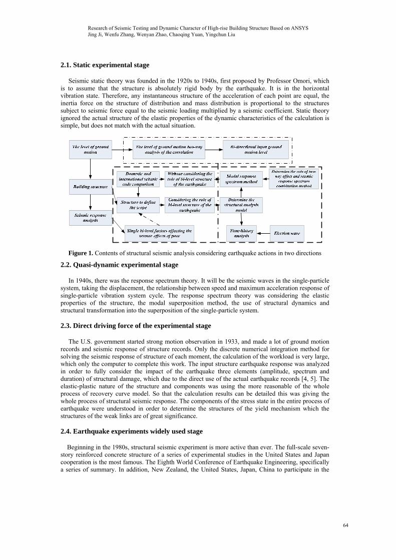
Figure 2. Layout of the analytical structure model with eccentricity in one direction
A lot of damage survey results show that the torsional response is one important reason caused by
the structure of earthquake damage. In this paper, theoretical analysis and examples research, and the intrinsic link between the influencing factors of the different indicators and indicators provide the necessary theoretical and data base, in order to access the control targets reversing effects of the three indicators mentioned above. When the structure of the reaction under study the vertical structure of eccentric direction of the unidirectional earthquake, due to the eccentric direction along the structure, the translational degrees of freedom will not be affected, for the establishment of the structural model of dynamic equations can only consider the floors of two degrees of freedom u and θ. The introduction
Research of Seismic Testing and Dynamic Character of High-rise Building Structure Based on ANSYS Jing Ji, Wenfu Zhang, Wenyan Zhao, Chaoqing Yuan, Yingchun Liu
65

of a rigid floor formula derivation assumes that only consider Japing modes and an order reversing vibration mode coupling reaction, floor lateral force resisting members does not consider itself reversing impact[8,9].
CS and CM, respectively, for just the heart and center of mass of the structure floor, the coordinate origin O located in the center of mass of the floor. es for the distance between just the heart and center of mass,
2 2 1 1 2 2 1 1
1 2
s
Ky x Ky x Ky x Ky xe
Ky Ky Ky
Where, Ky1 and Ky2 lateral stiffness of Y to the lateral force resisting components; Ky, for the floor Y to the total lateral stiffness,
( 1,2) iKy Ky i
Torsional response of Y to the earthquake caused only consider the center of mass at the Y to the translational degrees of freedom u and around the point of rotational degrees of freedom θ. Respectively in these two degrees of freedom to establish the structural dynamic equilibrium equation, plane stress analysis include: Y to the restoring force to the restoring force the Ky1 (u-θx1), and Ky2(u+θx2).
1 1 2 2( ) ( ) 0 mu Ky u x Ky u x
( ) 0 smu Ky u e
1 1 1 2 2 2 1 1 1 2 2 2( ) ( ) 0 rJ Ky u x x Ky u x x Kx y y Kx y y
0
r sJ Ky u e K
3.3 Computer model Introduction
ANSYS software is a financial structure, fluid, electric field, magnetic field, the sound field analysis in large general-purpose finite element analysis software. By ANSYS development, the world's largest finite element analysis software company, one that can, with most CAD software, interface, data sharing and exchange, such as Pro / Engineer, NASTRAN, Alogor, I-DEAS, AutoCAD and other modern one of the CAD tools in the product design.
The software consists of three parts: pre-processing module, analysis of the calculation module and post-processing module. Pre-processing module provides a powerful modeling and meshing tools, users can easily construct a finite element model; Analysis modules include structural analysis (linear analysis, nonlinear analysis, and highly non-linear analysis) , fluid dynamics, electromagnetic field analysis, analysis of the sound field, piezoelectric analysis and multi-physics coupling analysis can simulate the interaction of a variety of physical media, with a sensitivity analysis and optimization analysis capabilities; post-processing module can calculate the results in color contour gradient vector particle flow trace display, three-dimensional slice, transparent and translucent (can be seen within the structure) and graphically displayed, the calculation results are displayed in the graphs, form or outputs. The software provides more than 100 kinds of cell types used in the analog engineering structures and materials.
The basic equation of motion solved by an implicit transient dynamic analysis is,
( ) mx cx kx F t Where m is the mass matrix, c is the damping matrix, k is the stiffness matrix and F(t) is the load
vector. At any given time, t, this equation can be thought of as a set of "static" equilibrium equations that also take into account inertia forces and damping forces. The Newmark or HHT method is used to solve these equations at discrete time points. The time increment between successive time points is called the integration time step. For linear problems: 1) Implicit time integration is unconditionally stable for certain integration parameters. 2) The time step will vary only to satisfy accuracy requirements. For nonlinear problems: 1) The solution is obtained using a series of linear approximations (Newton-Raphson method), so
each time step may have many equilibrium iterations.
Research of Seismic Testing and Dynamic Character of High-rise Building Structure Based on ANSYS Jing Ji, Wenfu Zhang, Wenyan Zhao, Chaoqing Yuan, Yingchun Liu
66
The solution requires inversion of the nonlinear dynamic equivalent stiffness matrix. 2) Small, iterative time steps may be required to achieve convergence. 3) Convergence tools are provided, but convergence is not guaranteed for highly nonlinear problems.
The basic equations solved by an explicit dynamic analysis express the conservation of mass, momentum and energy in Lagrange coordinates. These, together with a material model and a set of initial and boundary conditions, define the complete solution of the problem. For Lagrange formulations, the mesh moves and distorts with the material it models, so conservation of mass is automatically satisfied. The density at any time can be determined from the current volume of the zone and its initial mass:
0 0
V m
V V Conservation of energy is expressed via:
12 2 2
xx xx yy yy zz zz xy xy yz yz zx zxe
For each time step, these equations are solved explicitly for each element in the model, based on input values at the end of the previous time step. Only mass and momentum conservation is enforced. However, in well posed explicit simulations, mass, momentum and energy should be conserved. Energy conservation is constantly monitored for feedback on the quality of the solution (as opposed to convergent tolerances in implicit transient dynamics).
4. High-rise buildings seismic simulation study 4.1 Model setting
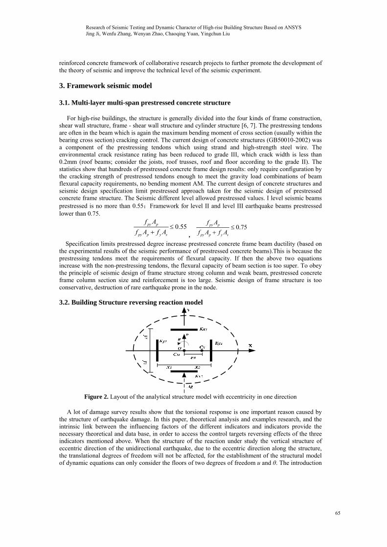
Frame - shear wall structure is the framework by the space beams, vertical shear walls and horizontal floor. The whole model is a two unit types: BEAM4 and SHELL63.Beams in the framework of beams and columns are used BEAM4 unit, shear walls and floor SHELL63 unit. BEAM4 unit parameters include the cross-section height, width, area and moment of inertia, cross-sectional form of selection rectangle.
1 2
3 4
X Y
Z
X
Y
Z
X Y
Z
XY
Z
UROTACEL
UROTACEL
UROTACEL
UROTACEL
Figure 3. Building structure load model
1.The bottom of the column cross-section was 500mm × 500mm, and the remaining layers of 450mm × 450mm.
Research of Seismic Testing and Dynamic Character of High-rise Building Structure Based on ANSYS Jing Ji, Wenfu Zhang, Wenyan Zhao, Chaoqing Yuan, Yingchun Liu
67
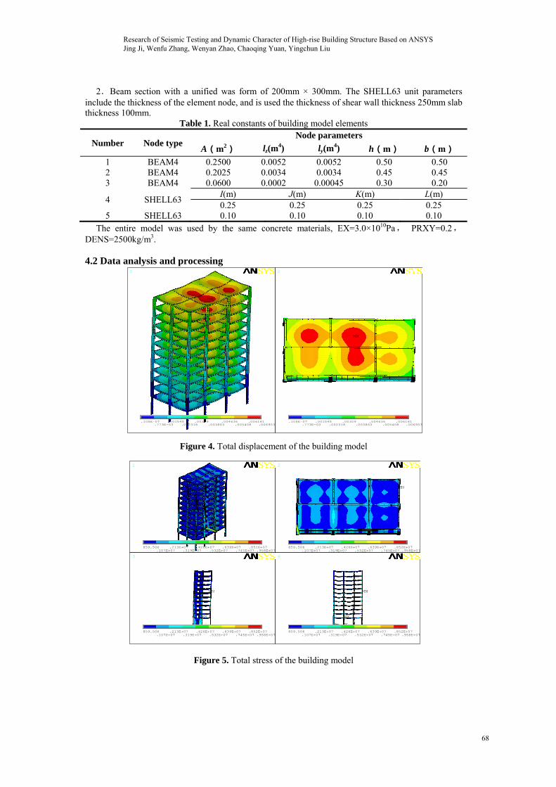
2.Beam section with a unified was form of 200mm × 300mm. The SHELL63 unit parameters include the thickness of the element node, and is used the thickness of shear wall thickness 250mm slab thickness 100mm.
Table 1. Real constants of building model elements
Number Node type Node parameters
A(m2) lz(m4) ly(m
4) h(m) b(m)
1 BEAM4 0.2500 0.0052 0.0052 0.50 0.50 2 BEAM4 0.2025 0.0034 0.0034 0.45 0.45 3 BEAM4 0.0600 0.0002 0.00045 0.30 0.20
4 SHELL63 I(m) J(m) K(m) L(m) 0.25 0.25 0.25 0.25
5 SHELL63 0.10 0.10 0.10 0.10 The entire model was used by the same concrete materials, EX=3.0×10¹⁰Pa, PRXY=0.2,
DENS=2500kg/m3.
4.2 Data analysis and processing 1
MN
MX
2
MN
MX
X Y
Z X
Y
Z
.105E-07.773E-03
.001545.002318
.00309.003863
.004636.005408
.006181.006953
.105E-07.773E-03
.001545.002318
.00309.003863
.004636.005408
.006181.006953
Figure 4. Total displacement of the building model
1
MN
MX
2
MN
MX
3
MN
MX
4
MN
MX
X Y
Z
X
Y
Z
X Y
Z
XY
Z
859.506.107E+07
.213E+07.319E+07
.426E+07.532E+07
.639E+07.745E+07
.852E+07.958E+07
859.506.107E+07
.213E+07.319E+07
.426E+07.532E+07
.639E+07.745E+07
.852E+07.958E+07
859.506.107E+07
.213E+07.319E+07
.426E+07.532E+07
.639E+07.745E+07
.852E+07.958E+07
859.506.107E+07
.213E+07.319E+07
.426E+07.532E+07
.639E+07.745E+07
.852E+07.958E+07
Figure 5. Total stress of the building model
Research of Seismic Testing and Dynamic Character of High-rise Building Structure Based on ANSYS Jing Ji, Wenfu Zhang, Wenyan Zhao, Chaoqing Yuan, Yingchun Liu
68
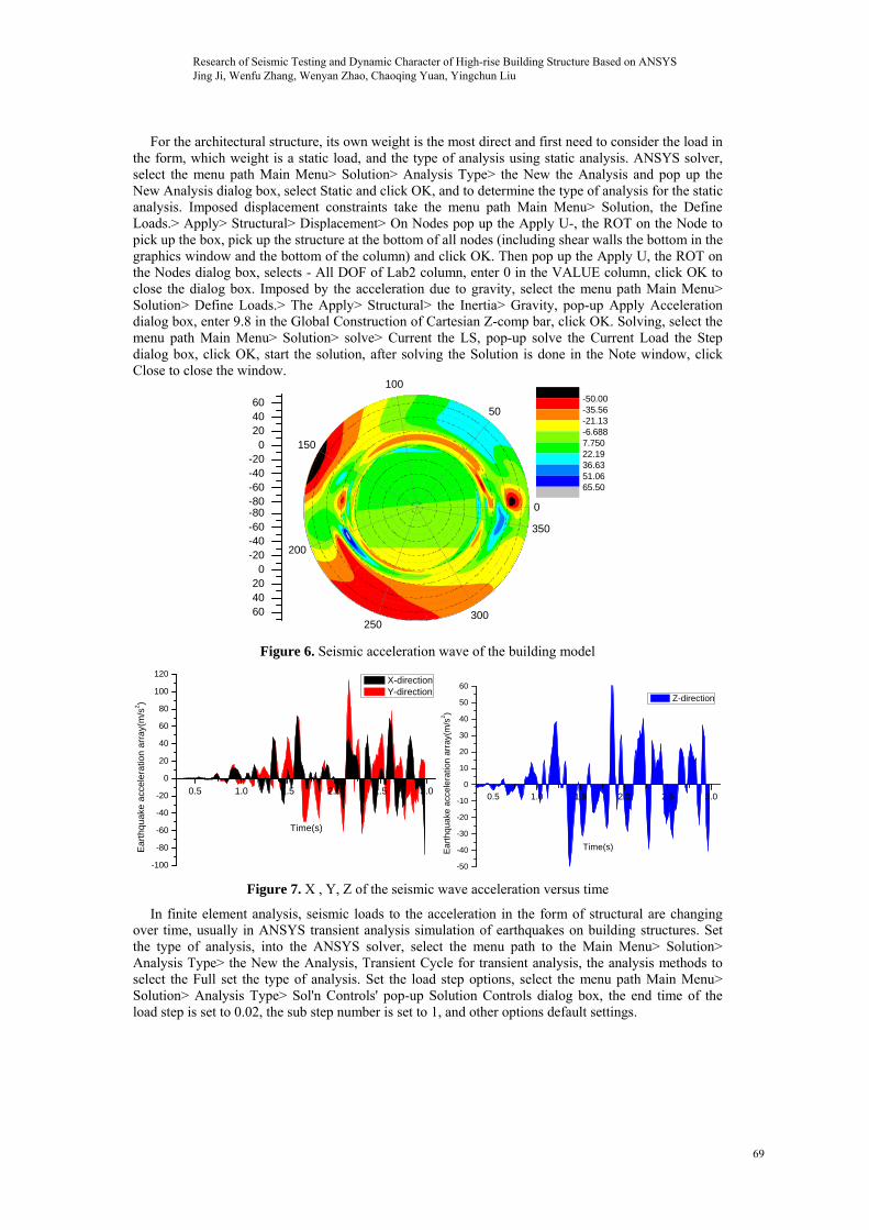
For the architectural structure, its own weight is the most direct and first need to consider the load in the form, which weight is a static load, and the type of analysis using static analysis. ANSYS solver, select the menu path Main Menu> Solution> Analysis Type> the New the Analysis and pop up the New Analysis dialog box, select Static and click OK, and to determine the type of analysis for the static analysis. Imposed displacement constraints take the menu path Main Menu> Solution, the Define Loads.> Apply> Structural> Displacement> On Nodes pop up the Apply U-, the ROT on the Node to pick up the box, pick up the structure at the bottom of all nodes (including shear walls the bottom in the graphics window and the bottom of the column) and click OK. Then pop up the Apply U, the ROT on the Nodes dialog box, selects - All DOF of Lab2 column, enter 0 in the VALUE column, click OK to close the dialog box. Imposed by the acceleration due to gravity, select the menu path Main Menu> Solution> Define Loads.> The Apply> Structural> the Inertia> Gravity, pop-up Apply Acceleration dialog box, enter 9.8 in the Global Construction of Cartesian Z-comp bar, click OK. Solving, select the menu path Main Menu> Solution> solve> Current the LS, pop-up solve the Current Load the Step dialog box, click OK, start the solution, after solving the Solution is done in the Note window, click Close to close the window.
-80-60-40-20
0204060
0
50
100
150
200
250300
350
-80-60-40-20
0204060
-50.00-35.56-21.13-6.6887.75022.1936.6351.0665.50
Figure 6. Seismic acceleration wave of the building model
0.5 1.0 1.5 2.0 2.5 3.0
-100
-80
-60
-40
-20
0
20
40
60
80
100
120
Ear
thqu
ake
acc
ele
ratio
n a
rray
(m/s
2)
Time(s)
X-direction Y-direction
0.5 1.0 1.5 2.0 2.5 3.0
-50
-40
-30
-20
-10
0
10
20
30
40
50
60
Ea
rth
quak
e a
cce
lera
tion
arr
ay(m
/s2)
Time(s)
Z-direction
Figure 7. X , Y, Z of the seismic wave acceleration versus time
In finite element analysis, seismic loads to the acceleration in the form of structural are changing over time, usually in ANSYS transient analysis simulation of earthquakes on building structures. Set the type of analysis, into the ANSYS solver, select the menu path to the Main Menu> Solution> Analysis Type> the New the Analysis, Transient Cycle for transient analysis, the analysis methods to select the Full set the type of analysis. Set the load step options, select the menu path Main Menu> Solution> Analysis Type> Sol'n Controls' pop-up Solution Controls dialog box, the end time of the load step is set to 0.02, the sub step number is set to 1, and other options default settings.
Research of Seismic Testing and Dynamic Character of High-rise Building Structure Based on ANSYS Jing Ji, Wenfu Zhang, Wenyan Zhao, Chaoqing Yuan, Yingchun Liu
69
1
MN
MX
2
MN
MX
3
MN MX
4
MNMX
X Y
Z
X
Y
Z
X Y
ZXY
Z
-.572307-.45154
-.330773-.210006
-.089238.031529
.152296.273063
.393831.514598
-.572307-.45154
-.330773-.210006
-.089238.031529
.152296.273063
.393831.514598
-.572307-.45154
-.330773-.210006
-.089238.031529
.152296.273063
.393831.514598
-.572307-.45154
-.330773-.210006
-.089238.031529
.152296.273063
.393831.514598
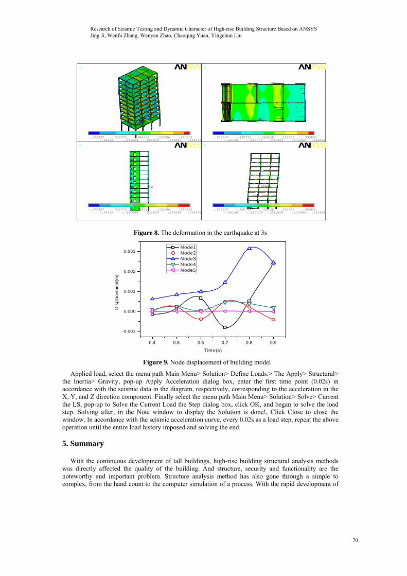
Figure 8. The deformation in the earthquake at 3s
0.4 0.5 0.6 0.7 0.8 0.9
-0.001
0.000
0.001
0.002
0.003
Dis
pla
cem
ent
(m)
T ime(s)
Node1 Node2 Node3 Node4 Node5
Figure 9. Node displacement of building model
Applied load, select the menu path Main Menu> Solution> Define Loads.> The Apply> Structural> the Inertia> Gravity, pop-up Apply Acceleration dialog box, enter the first time point (0.02s) in accordance with the seismic data in the diagram, respectively, corresponding to the acceleration in the X, Y, and Z direction component. Finally select the menu path Main Menu> Solution> Solve> Current the LS, pop-up to Solve the Current Load the Step dialog box, click OK, and began to solve the load step. Solving after, in the Note window to display the Solution is done!, Click Close to close the window. In accordance with the seismic acceleration curve, every 0.02s as a load step, repeat the above operation until the entire load history imposed and solving the end.
5. Summary
With the continuous development of tall buildings, high-rise building structural analysis methods was directly affected the quality of the building. And structure, security and functionality are the noteworthy and important problem. Structure analysis method has also gone through a simple to complex, from the hand count to the computer simulation of a process. With the rapid development of
Research of Seismic Testing and Dynamic Character of High-rise Building Structure Based on ANSYS Jing Ji, Wenfu Zhang, Wenyan Zhao, Chaoqing Yuan, Yingchun Liu
70
high-rise buildings, many of the architectural buildings were form of the bottom the podium and upper towers. The emergence of these complex architectural forms has brought many new problems to the seismic analysis of structures and seismic design. This paper describes the building seismic on a trial basis, using the ANSYS general purpose finite element software for seismic analysis of the tall building structures. Then we build the actual finite element model to simplify the steel structure concrete columns, and the analysis structure of the static condition. According second phase of the seismic design, the first phase of multi-elastic was analyzed of earthquake effect on the structure. The dynamic characteristics of the entire structure were determined with modal analysis. The main three incentive direction and modal order analysis as a dynamic basis were identified. Meanwhile, the response spectrum was analyzed to determine the dynamic response of structures under seismic action, to draw the maximum internal force of the structure of each component, providing the basis for the structural design. Meanwhile, the dynamic response of structures under seismic action was analyzed, which draw the maximum internal force of the structure of each component, and provide the basis for the structural design. Multi-layer multi-span prestressed concrete structures, reinforcement of the main beam were controlled by the gravity load combination. Prestressing tendons in the beam was controlled by the maximum bending moment of cross section, usually within the bearing cross section. 6.Acknowlegements
The study described in this paper was supported by the Heilongjiang Provincial Department of Education Science and technology research project (project number: 12511022) and The National Natural Science Foundation of China (project number: 51178087).These supports are gratefully acknowledged. 7. References [1] M. Shahria Alam, M. Moni, S. Tesfamariam, "Seismic Overstrength and Ductility of Concrete
Buildings Reinforced with Superelastic Shape Memory Alloy Rebar", Engineering Structures, vol. 34, no. 1, pp. 8-20, 2012.
[2] Aliaari, M, A. Memari, "Analysis of Masonry Infilled Steel Frames with Seismic Isolator Subframes", Engineering Structures, vol. 27, no. 4, pp. 487-500, 2005.
[3] Alemdar Bayraktar, Barış Sevim, Ahmet Can Altunişik, "Finite Element Model Updating Effects on Nonlinear Seismic Response of Arch Dam-reservoir-foundation Systems" Finite Elements in Analysis and Design, vol. 47, no. 2, pp. 85-97, 2011.
[4] Betti, M, A. Vignoli, "Assessment of Seismic Resistance of a Basilica-Type Church under Earthquake Loading: Modeling and Analysis" Advances in Engineering Software, vol. 39, no. 4, pp. 258-283, 2008.
[5] Hong Fan, Q S Li, Alex Y Tuan, Lihua Xu, "Seismic Analysis of the World’s Tallest Building", Journal of Constructional Steel Research, vol. 65, no. 5, pp. 1206-1215, 2009.
[6] Hou, X, H. Tagawa, "Displacement-Restraint Bracing for Seismic Retrofit of Steel Moment Frames", Journal of Constructional Steel Research, vol. 65, no. 5, pp. 1096-1104, 2009.
[7] Jan, T, "An upper-bound Pushover Analysis Procedure for Estimating the Seismic Demands of High-rise Buildings", Engineering Structures, vol. 26, no. 1, pp. 117-128, 2004.
[8] Jun Ji, Amr S. Elnashai, Daniel A. Kuchma, "An Analytical Framework for Seismic Fragility Analysis of RC high-rise Buildings", Engineering Structures, vol. 29, no. 12, pp. 3197-3209, 2007.
[9] İlker Kazaz, Ahmet Yakut, Polat Gülkan, "Numerical Simulation of Dynamic Shear Wall Tests: A Benchmark Study", Computers & Structures, vol. 84, no. 8, pp. 549-562, 2006.
[10] Hongxia Duan, Shouju Li, Yingxi Liu, "A Nonlinear Two-stage Damage Identification Method for Steel Frames", IJACT: International Journal of Advancements in Computing Technology, vol. 3, no. 4, pp. 109-120, 2011.
[11] Lv Hui, "The Study on Building Mixed Structure Anti-seismic Design based on Sliding Mode Control and Fuzzy Logic Control", AISS: Advances in Information Sciences and Service Sciences, vol. 4, no. 1, pp. 124-131, 2012.
Research of Seismic Testing and Dynamic Character of High-rise Building Structure Based on ANSYS Jing Ji, Wenfu Zhang, Wenyan Zhao, Chaoqing Yuan, Yingchun Liu
71