research on presbyopia optometry method based on diopter
TRANSCRIPT

Journal of Multimedia Processing and Technologies Volume 8 Number 1 March 2017 11
Research on Presbyopia Optometry Method Based on Diopter Regulation andCharge Couple Device Imaging Technology
Qi Zhao, Xiaoxuan Wu, Jun Zhou, Xiao Wang, Ruifeng Liu, Jing GaoDepartment of Ophthalmology, the Second Hospital of Dalian Medical UniversityDalian, Liaoning, 116023, [email protected]
ABSTRACT: With the development of photoelectric technology and single-chip microcomputer technology, the objective(automatic) optometry technology is becoming more and more mature. This paper proposed a presbyopia optometry methodbased on diopter regulation and CCD (Charge Couple Device) imaging technology and, in the meantime, designed the lightpath of the measurement system. This method projects a test figure to the eye ground of tested eye and then the reflected imagefrom eye ground is detected by CCD. At last the image is automatically identified by computer by which the far point and nearpoint diopter are determined and thus the glasses parameter is calculated. This is a full automatic objective optometrymethod, which eliminates subjective factors of the tested subject. This method can acquire the glasses parameter of presbyopiaaccurately and quickly, and can be used to measure the glasses parameter of hyperopia, myopia and astigmatism.
Keywords: Visual optics, Diopter regulation, CCD devices, Image identification
Received: 7 September 2016, Revised 13 October 2017, Accepted 20 October 2017
© 2017 DLINE. All Rights Reserved
1. Introduction
Human eyes as a biological optic system, has multiple states such as emmetropia, hyperopia, myopia and astigmatism, whichvaries from person to person. Besides from emmetropia, all the states negatively influences definition of human eyes whenseeing things, which is called vision deficiency (also called diopter abnormity)[1]. Vision deficiency is normally adjusted byoptometry besides from surgery, laser operation and drug therapy. In the recent decade, as the photoelectric technology andsingle-chip microcomputer technology developed, the objective (automatic) optometry has become more and more mature. Itcan completely eliminate the subjective factors of the tested subject and acquire the glasses parameter accurately and quickly.
CCD was invented by Bell Laboratory in late 1960s. It is a special semiconductor which consists of lots of independent lightsensors; the sensors are normally in matrix arrangement [2-4]. At first, CCD was used as a new PC storage circuit, but soon it hadlots of other potential applications, including signal and image (light sensitivity of silicic) management [5]. Photosensitiveelement of most digital cameras is CCD.

12 Journal of Multimedia Processing and Technologies Volume 8 Number 1 March 2017
Prebyopia occurs when we get older; it is caused by the variation of physiological function. Conventional optometry appliesoptic insertion and try-on on the basis of estimation according to age and experiential data [6]. Up to now, there is no objectivemeasuring method. This paper proposed a method measuring the near and far point on the basis of diopter regulation principleand then designed an objective optometry unit of optical system based on CCD imaging technology.
2. Diopter Regulation of Human Eyes And Imaging Property of Presbyopia
Human eye automatically adjusts focal length when observing objects at different distance to make the image projected onretina, thus we can see things clearly. The automatic adjustment of focal length is what we call diopter regulation [7]. The diopterregulation range is the difference between far point diopter and near point diopter, which varies as the age grows. Far pointdiopter is the reciprocal of the furthest distance (the unit m) human eyes can see clearly when entirely relaxed. The furthestdistance emmetropic eye can project clear image on retina, when relaxed, is infinity, hence the far point diopter is 0; the furthestdistance myopic eye can see clearly is- 2m, hence the near point diopter is - 0.5. Near point diopter is the reciprocal of the nearestdistance human eye can see with the maximum regulation [8].The near point distance of emmetropic human eye of 20 years oldis – 100mm thus the near point diopter is – 10, and as the far point distance is infinity the maximum regulation range is 10 diopter.
When emmetropic eye become presbyopia, the far point distance does not change and stays as infinity, so the relevant far pointdiopter is 0; whereas the near point distance become further and the absolute value of relevant near point diopter decreases,thus the regulation range narrows. The near point distance of emmetropic human eye of 50 years old is – 400mm of which therelevant near diopter is – 2.5, thus the regulation range is 2.5 diopter. The narrowing of regulation range is the symptom ofpresbyopia, and is a physiological phenomenon which relates to age, so all the aged suffer from presbyopia.
Imaging property of presbyopia refers to figure 1. The image of the object point at infinity forms image on retina(expressed asfine solid line); image of the object point at finite distance forms image at F point behind retina(expressed as light ray with arrow)and form light spot on retina, hence the image is blurry. If we install a convex lens before the eye, the object point at infinitedistance forms clear image on retina (dash line). The convex lens is the presbyopic glasses as we usually say which replaces thecrystalline lens of presbyopic and has the function of embossment, thereby presbyoptic adjustment is realized.
Figure 1. Imaging property of presbyopic
Since presbyopic is characterized by narrowing of regulation range, and diopter regulation range is the difference between farpoint and near point, we can acquire the presbyopic glasses parameter by measuring the far point diopter and near point diopterof the eye and applying clinical experiential formula of ophthalmology [9].
Near point of presbyopic becomes further and normally object can be observed clearly when placed further. But if the object issmall and placed too far even beyond the distinguish ability extremity, we can not see it clearly neither. So, in order to read andobserve normally, we have to adjust presbyopic with glasses.
3. The Correlation Between Far Point And Near Point Diopter And Presbyopic Diopter
Regulation range (ability) of human eye is the difference between far point and near point diopter, that is ΔD=DY – DJ [10,11].Clinical experience thinks, when ΔD ≥ 3D, the presbyopic symptom of human eye is void or slight; and when ΔD < 3D, thepresbyopic symptom is severe [12]. The regulation range of emmetopia eye of 48 years old is 3D, so normally; people older than48 years have to wear glasses to adjust presbyopia. In clinic, presbyopia diopter (glasses diapoter) is defined as
Journal of Multimedia Processing and Technologies Volume 8 Number 1 March 2017 13
DL = DJ - D0 + ΔD/3 (1)
In the equation, D0 is the diopter relevant with reading distance which is normally –m/3, thus D0 = -3D.
Figure 2 diagrammatizes equation (1) vividly and clearly: when human eye is relaxed, it can see object at far point PY clearly, andwith some regulation ability it can see the object at P1 (P1 is within the regulation range), then adjust with glasses (diapoter valueis DL), the eye can see the object at reading point P0 clearly. Here, near point PJ is beyond P0.
Figure 2. Diagram of presbyopia adjustment
In equation (1), the configuration of ΔD /3 is reasonable, it is clinical experiential data of ophthalmology and its value is 1/3 of theremaining regulation ability (ΔD). Its physical meaning is: when adjust presbyopia applying glasses, we have to make sure wecan invoke 2/3 of the remaining regulation ability. If presbyopia reads without applying regulation ability but directly adjust withglasses from PY to P0, the eye senility may be accelerated as ciliaris and crystalline lens are at dormant state for a long time. Onthe contrary, if we invoke all the regulation ability, our eyes get tired easily.
If an eye has lost all the regulation ability, which means ΔD = 0, its far point coincides with near point, and the equation ofpresbyopia changes from equation (1) to:
DL =DJ - D0 (2)
The physical meaning of equation (2) is: the far point of the relaxed eye is directly adjusted from PY (also PJ) to P0 with glasses.
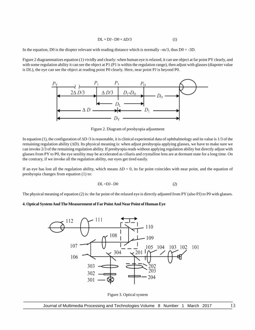
4. Optical System And The Measurement of Far Point And Near Point of Human Eye
Figure 3. Optical system

14 Journal of Multimedia Processing and Technologies Volume 8 Number 1 March 2017
The optical system shown in figure 3 can measure far point diapoter and near point diapoter, and can also directly measurehyperopia, myopia and astigmatic degree. In the figure, sequence 100 is projected light path, sequence 200 is measurement lightpath and sequence 300 is fixation light path. Near-infrared source 101 lights up diaphragm 105 and forms ringlike image thenentered eyeball 112. To emmetropic eyes, the image may be projected on retina and reflects there; then the image goes backthrough the previous pathway and reflects on spectral 201; after that, the image refracts to diaphragm 202 which eliminates straylights and form ringlike image on area array CCD; the image has fixed diameter. If the tested eye is abnormal eye, the scannerconsists of 109 and 110 compensates the light and still projects the ringlike image on retina; then we get ringlike image of thesame diameter and the compensation amount of the scanner is the diapoter of far point and near point. If tested eye is astigmatic,the image on CCD will be ellipse and we can get astigmatic degree and axial angle parameter from the length, minor axis andgradient of the ellipse.
In fixation light path, fixation vision image 302 is shined by visible light source 301, then it reflects on splitter 304 and refract totested eye. Tested eye stare at fixation vision image and regulate diapoter as the scanning of the scanner to get clear vision offixation vision image, thus we can get the diapoter of far point and near point. The process is shown in figure 4.
Figure 4. The correlation between scanning diapoter and diameter of ringlike image
Figure 4 shows: (1) As scanning is performed beyond the regulation range of the tested eye, the tested eye can not see thingsclearly and can not follow the fixation vision image, thus the diapoter value is fixed and focal length of optical system changesduring the scanning (or scanning diapoter) which leads to the variation of diameter of ringlike image on CCD.
(2)Between far point and near point, the scanning is within the regulation range of tested eye. As the eye can clearly see thingsand it can regulate during the canning when follow fixation vision image, the diapoter value changes during this process. Thediappoter value variation of tested eye neutralizes the scanning diapoter, so the diameter of the ringlike image on CCD stays thesame.
The far point and near point of tested eye are at the two scanning positions where the diameter of ringlike image changes. At thistime, the scanning diapoter is the far point diapoter and near point diapoter of the tested eye [13, 14]. Substitute the acquired farpoint and near point diapoters in equation (1) we get the presbyopia diapoter. Characteristics of the ringlike image are recognizedby the Single Chip Microcomputer, and the whole process is performed by the system automatically and tested object can notfeel.
5. Conclusions
To sum up, we get three conclusions from this paper.
(1) It forms a full-automatic objective presbyopia optometry method by measuring the far point and near point diapoter andcalculating the presbyopia diapoter applying scientific computing method.
(2) Through the analysis of the optical system, we find this method competent for measuring the glasses parameter of hyperopia,myopia and astigmatism. A machine applying this method serves several purposes.
(3) As the existed full-automatic objective optometry unit used for measuring myopia, hyperopia and astigmatism only needs thetested eye to be relaxed but no diapoter regulation is required, it accomplishes the whole measurement within 1 second. Thepresbyopia method of this paper which based on human eye diapoter regulation and CCD imaging technology needs a bit more

Journal of Multimedia Processing and Technologies Volume 8 Number 1 March 2017 15
time. It costs some time for the tested eye to focus on the fixation vision image and regulate the diapoter during the scanning.So it needs in-depth research and experiment to determine the scanning time. However, this uncertainty does not alter thevalidity and feasibility of the principle of this method.
References
[1] He, Jian., Tan, Shaojian., Liang, Hao.,Li, Xia . (2011). Comparison of Presbyopic Refraction between Conventional RefractiveProcedure and Medical Refractive Procedure in Pseudophakic Eye. International J of Ophthalmology. 11 (7) 1255-1257.
[2] Xue, Hong(2013). Study on the Experiment of Newtonian Rings Based on the CCD Imaging Technology. J of WeinanTeachers College. 28 (9) 21-24.
[3] Liu, Chang. (2014). Research of Refractive Index Measurement Technique based on CCD Imaging Technology. ChangchunUniversity of Science and Technology.
[4] Xia, Weiqiang., Zhou, Yuan., Shi, Ming. (2011). Advances in Two-photon Imaging Technology. Chinese J of MedicalInstrumentation. 35 (3) 204-208.
[5] Hu, Changhua., Qin, Junyuan., Yang, Zhanjun. (2014). Brief Introduction of Ultraviolet Imagery Detecting Technique andIts Application in Power Grid. Gansu Science and Technology. 30 (16) 53-54.
[6] Li, Shixiang., Zhao, Yuyang., Liu, Xueyan., Ma, Lihong., Zhao, Aihong., Jiang, Xiaonan. (2012). Clinical Study of ShotfileSoftware for the Correction of Presbyopia. International J of Ophthalmology. 12 (10) 1882-1886.
[7] Wang, Qian . (2013). Comparation of Presbyopic ADD of Subjective Refraction and the Theoretical Results. Nei Mongol J ofTraditional Chinese Medicine. 32 (18) 79-80.
[8] Jing, Yamen. (2011). Analysis of Judgement Value Comprehensive Optometry Unit Attach to Presbyopia Glasses. ChinaHealthcare Innovation. 6 (13) 48.
[9] Wang, Lishu., Wang, Haiying., Zhu, Change. (2014). Optometry and Fitting Method of Presbyopia and the Problems Solving.China Glasses Science-Technology Magazine. (17) 103-107.
[10] Xu, Jingxin. (2012). Discussion on presbyopia optometry. China Glasses Science-Technology Magazine (1) 113-115.
[11] Bo Liu, Zhigang Zhen, Yan Fang. (2012). Application Study of Skiascopie in Screening and Diagnosis of SuspectedKeratoconus. J of Dalian Medical University. 34 (3) 252-256.
[12] Cui, Yin., Zeng, Jin., Guo, Haike., Wang, Jun., Xie, Wenjuan., Li, Zhongming., Liao, Weixiong. (2011). Clinic al Researchesof Conductive Cornea Thermal Forming and Ultrasonic Emulsification Combining Single Focus Artificial Lens Implanting onPresbyopia. The Journal of Practical Medicine. 27 (20) 3686-3688.
[13] Guanpeng Zeng, Changjun Lan. (2011). Presbyopic Optometry by Refractor: Observations on 100 Cases. Practical Journalof Clinical Medicine. 8 (4) 96-98.
[14] Zhao, Jianjun., Ye, Jiandong., Zhu, Chuanfang. (2014). Practice and Experience in Clinical Check for Older MyopicProgressive Lens. Continuing Medical Education. 28 (4) 51-53.