research on the winding control system in winding vacuum ...journal.it.cas.cz/61(2016)-4a/paper23...
TRANSCRIPT

Acta Technica 61, No. 4A/2016, 257–268 c© 2017 Institute of Thermomechanics CAS, v.v.i.
Research on the winding controlsystem in winding vacuum coater
Wenbing Jin1, Suo Zhang1, Yinni Jin2
Abstract. A method of control of the winding speed and rewinding or unwinding tensionof the rolling high-vacuum continuous coating machine is proposed. The method is based oncontrol of the armature current of the DC motor. Its time variation is caused by a lot of factors,such as the film winding tension, motor constant friction, electrical load that can change with thespeed of the friction, unload acceleration and deceleration resistance, acceleration and decelerationwith a load resistance, current introduced by the rolling tension of the film and others. All thesefactors may influence the tension. Thus, the control of the rolling tension can be achieved throughcontrol of the armature current. In order to find the relation between this current and tension, wefirst established a mathematical model in accordance with the principle of the rewinding system.Based on its analysis, we designed an alternative rewinding automatic control system. Our workshows that the proposed automatic control system exhibits a quite satisfactory performance andproperties. This is also confirmed by its successful application in industry.
Key words. Winding control, rewinding; unwinding, tension, armature current, speed.
1. Introduction
There are three schemes of existing winding control for selection: one is thetension closed-loop control scheme (speed mode). A feedback signal derived fromthe tension detecting device cooperates with the tension setting value to constitutea PID closed-loop control circuit, which adjusts motor speed to achieve the purposeof tension control. The second kind is tension open-loop control scheme (torquemode). By controlling the output torque of the motor, the objective tension canbe controlled. The principle is that by setting the value of tension and volume, thetorque can be calculated. This scheme does not need tension detection feedback,but for frequency converter working method and closed-loop vector control mode, aspeed measuring coder and a reel diameter sensor must be equipped. In addition,the influence of rotational inertia in acceleration and deceleration process should beconsidered. The third kind is the tension closed-loop control scheme (torque mode).
1Zhejiang Institute of Mechanical & Electrical Engineering, Hangzhou, 310000, China2School of Lehigh University, 27 Memorial Drive West, PA 18015-3086, USA
http://journal.it.cas.cz
258 WENBING JIN, SUO ZHANG, YINNI JIN
The tension detection feedback closed-loop control is added on the open-loop tensioncontrol scheme to realize the technique. The working principle is that PID closed-loop circuit can be obtained and output torque command can be adjusted by tensiondetection feedback signal and tension setting value, which would guarantee the highprecision of tension control. These above control methods all should be equippedwith a feedback sensor measuring the tension or radius.
Usually, the winding part is installed in the vacuum chamber, and vacuum degreeis there high when working. The more components installed in vacuum chamber, themore poles elicited from the lead wires can greatly influence the vacuum degree. Inaddition, sensor could cause discharge when the tension or speed increases in high-vacuum environment. A control system without rewinding/unwinding tension sensorand reel diameter sensor was proposed to meet the requirements of the performance.The tension values can be obtained and controlled by two parameters: DC motoroutput torque and winding diameter.
2. Methods
2.1. Profile of continuous high–vacuum winding coater
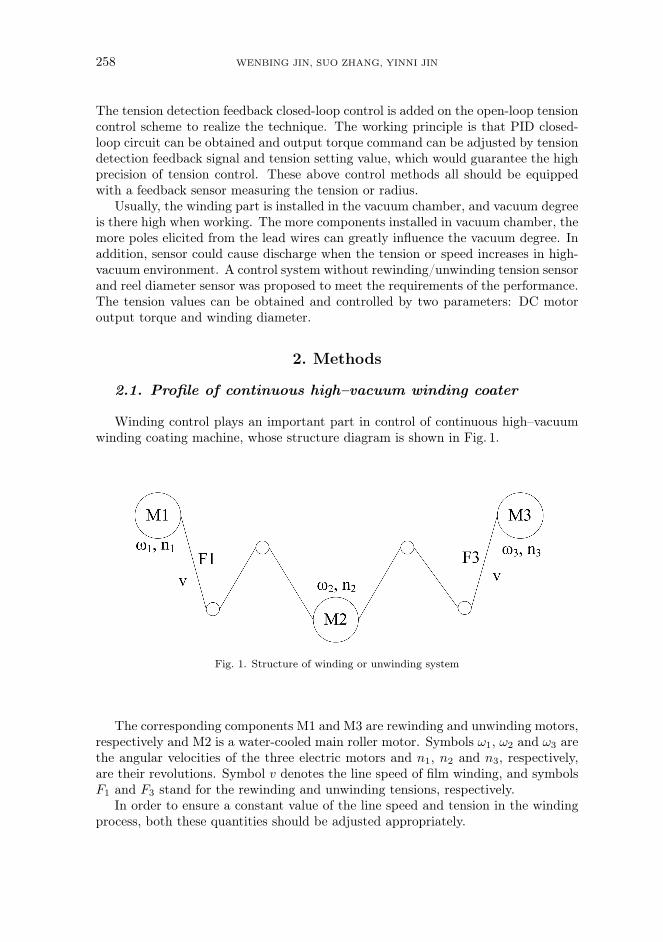
Winding control plays an important part in control of continuous high–vacuumwinding coating machine, whose structure diagram is shown in Fig. 1.
Fig. 1. Structure of winding or unwinding system
The corresponding components M1 and M3 are rewinding and unwinding motors,respectively and M2 is a water-cooled main roller motor. Symbols ω1, ω2 and ω3 arethe angular velocities of the three electric motors and n1, n2 and n3, respectively,are their revolutions. Symbol v denotes the line speed of film winding, and symbolsF1 and F3 stand for the rewinding and unwinding tensions, respectively.
In order to ensure a constant value of the line speed and tension in the windingprocess, both these quantities should be adjusted appropriately.
RESEARCH ON THE WINDING CONTROL 259
2.2. Analysis of winding motor
We take DC motor M1 for example. The motor is described by several equations.The equation for voltage can be written in the form
Ua1 = Ra1ia1 + La1dia1dt
+ E1 = Ra1ia1 + La1dia1dt
+Ke1Φ1n1 , (1)
where Ua1 is the armature voltage, Ra1 denotes the armature resistance, La1 standsfor the armature leakage inductance, E1 represents the armature electromotive force,Φ1 is magnetic flux, n1 stands for the motor speed and Ke1 represents the torqueconstant.
As quantities Ra1, La1, Ke1 and Φ1 may be considered constant, we can putKe1Φ1 = K1, so that
Ua1 = Ra1ia1 + La1dia1dt
+K1n1 . (2)
The effective torque of rewinding control is described by the equation
TL1 = F1R1 . (3)
The relationship between motor rotation angular velocity ω1 and motor speed n1is
ω1 =2π
60n1 . (4)
Now, we will deal with the analysis of the load of M1. There are many parameterswe should consider, for example the film winding tension, constant friction force ofload, variable friction coming from the rotation of load, no-load speed resistance,loading speed resistance, etc. Symbol ia1 denotes the armature current, which is thesum of the currents passing through the 5 parts.
ia1 = iT1 + iFC1 + iFω1 + iJC1 + iJω1 , (5)
where
1. Current ia1 varies with the change of tension and coil diameter by the formula
iT1 =F1R1
KT1Φ1=
1
KT1Φ1
30v
πn1F1 . (6)
2. Current iFC1 can be obtained when the system is to overcome the constantfriction; the current is derived when the system is under the no-load workingstate, and when the speed is a stable low speed. It is normally obtained whenthe system is working at the minimum speed (close to 0 rpm) and in a no-loadworking state, which is of the constant character.
3. Current iFω1 is obtained when the system is to overcome variable frictionforce: the current and motor speed n1 have a linear curve in a certain speed
260 WENBING JIN, SUO ZHANG, YINNI JIN
range. There holdsiFω1 = K2n1 , (7)
where K2 is a constant value.
4. Current iJC1 is an inherent acceleration and deceleration current of machinecaused by load inertia, which is proportional to variation rate of the motorspeed; it is given by the formula
iJC1 = Jc11
KT1Φ1
dω1
dt= Jc1
1
KT1Φ1
2π
60
dn1dt
, (8)
where Jc1 is the no-load inherent inertia. Its value is constant and can beobtained from the no-load test. The rated voltage is added to the no-loadmotor, the time t is calculated when the rewinding system accelerates from0 rpm to the nominal speed ωN . The current iJc can be obtained when themotor works at the rated speed according to the formula
iJc = i− iFc − iFω , (9)
where iFc refers to the current when the no-load motor works at a stableminimum speed and iFω is the current obtained when the motor works at therated speed ωN to overcome the variable friction force. The value of currentiFω may be obtained from the relation
Jc1 = iFωt
ωNKT1Φ1 . (10)
5. Current iJω1 is an acceleration and deceleration current caused by the changeof winding inertia of the film coater in the process of winding. It is given bythe formula
iJω1 =J1
KT1Φ1
dω1
dt=
1
2
∑(mir
2i )
KT1Φ1
dω1
dt=
=1
2
R21πR
21L1ρ1
KT1Φ1
dω1
dt=π2
60
ρ1L1R41
KT1Φ1
dn1dt
. (11)
Here, ρ1 is the density of winding film, L1 is the width of the winding film, R1
is the radius of winding film roll. The numerical value of R1 is continuouslychangeable in the winding process.
When the minimal volume diameter of the core is Rmin 1, then
iJω1 =π2
60
ρ1L1
KT1Φ1
dn1dt
(R41 −R4
min 1) , (12)
and after substitution R1 = 30v/(πn1) we finally obtain
iJω1 =π2
60
ρ1L1
KT1Φ1
dn1dt
(304v4
π4n41−R4
min 1
). (13)
RESEARCH ON THE WINDING CONTROL 261
Substitution of (6), (7), (10) and (13) into (5) provides
ia1 =1
KT1Φ1
30v
πn1F1 + iFC1 +K2n1 + Jc1
1
KT1Φ1
2π
60
dn1dt
+
+π2
60
ρ1L1
KT1Φ1
dn1dt
(304v4
π4n41−R4
min 1
)= iFC1 +
30
KT1Φ1π
v
n1F1 +K2n1 +
+Jc1
KT1Φ1
π
30
dn1dt
+304
60π2
ρ1L1
KT1Φ1
v4
n41
dn1dt
− π2
60
ρ1L1R4min 1
KT1Φ1
dn1dt
. (14)
2.3. Analysis of winding motor and main rolling motor
A similar equation for motor M3 can be obtained as above
ia3 = iT3 + iFC3 + iFω3 + iJC3 + iJω3 =1
KT3Φ3
30v
πn3F3 + iFC3 +K4n3 +
+ Jc31
KT3Φ3
2π
60
dn3dt
+π2
60
ρ3L3
KT3Φ3
dn3dt
(304v4
π4n43−R4
min 3
)=
= iFC3 +30
KT3Φ3π
v
n3F3 +K4n3 + Jc3
1
KT3Φ3
2π
60
dn3dt
+
+304
60π2
ρ3L3
KT3Φ3
v4
n43
dn3dt
− π2
60
ρ3L3R4min 3
KT3Φ3
dn3dt
. (15)
Finally, the revolutions of the main rolling motor are described by the followingdifferential equation
Tm2Ta2d2n2dt2
+ Tm2dn2dt
+ n2 =ua2
Ke2Φ2− 1
KT2Ke2Φ22
(Ta2
dTL2dt
+ TL2
), (16)
where Tm2, Ta2 and TL2 represent the electric time constant of main rolling motorM2, armature circuit and winding vacuum coater with the winding film width of L,respectively. These parameters are given by the formulae
Tm2 =JG2Ra2
KT2Ke2Φ22
, Ta2 =La2
Ra2.
3. Results
The main rolling motor is used to keep the film linear velocity constant. Themechanism design considered that when the tension of winding/unwinding motor isabove 50N and when winding tension F3 is slightly higher than 5%–10% of unwindtension F1 in actual use, the film coater would not slip in the main rolling motor.Thus, we can draw the conclusion that a constant line speed could be kept in filmwinding process as long as the rotation speed of main rolling motor is constant.
262 WENBING JIN, SUO ZHANG, YINNI JIN
Fig.
2.Control
functionalblock
diagramof
thehom
eroll
motor
RESEARCH ON THE WINDING CONTROL 263
Fig.3.
Con
trol
system
blockdiagram
oftheho
merollmotor
264 WENBING JIN, SUO ZHANG, YINNI JIN
Line speed V , main rolling motor revolutions n2 and angular velocity ω2 areconnected by the relation
V = ω2R2 =2π
60R2n2 , (17)
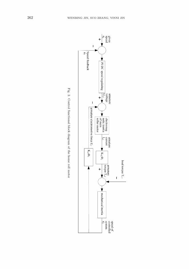
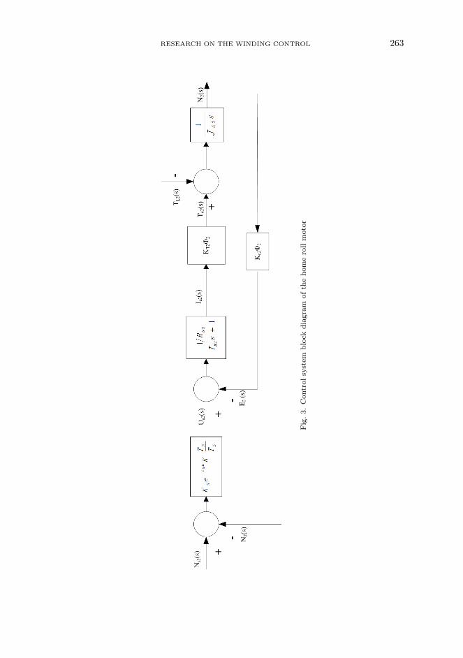
where R2 is the radius of main rolling motor, which is a constant value.The control scheme of the main roller motor is PI control of DC speed regulating
system. The control principle block diagram is shown in Fig. 2, and the transferfunction block diagram is shown in Fig. 3.
4. Discussion
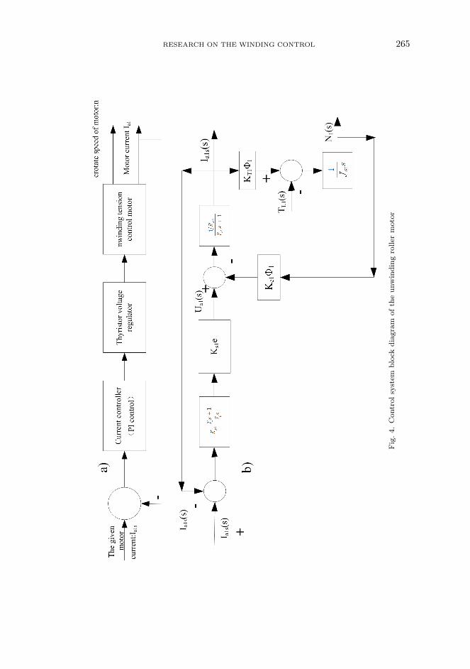
According to formula (14), the working current of the motor is determined bydetecting the rotate speed of the motor n1 and linear velocity v of the film coater,when a certain value of unwinding motor tension is given. So the tension controlwould be turned to the working current control. The control system block is shownin Fig. 4, where, Ia1s is the given working current of the motor calculated fromequation (14) for the given tension value F1.
The tension control in the winding part could be transformed to the currentcontrol which is similar to the unwinding part. The motor working current Ia3s wascalculated from equation (15) .
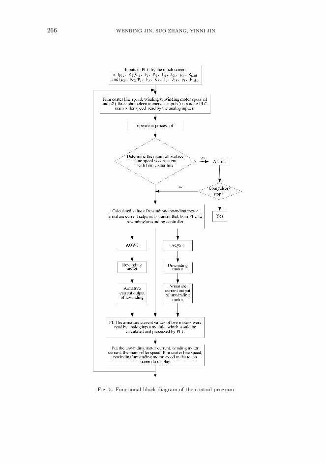
The parameters of control system wiring are shown in Table 1, and the flow chartis shown in Fig. 5.
Table 1. Parameters of control system wiring
HMI touchpad
S7-200CPU226CN
EM235 4AI/1AQ EM232 2AQ
No Address Function Component model
1 I0.0–I0.2 winding rotate speed optical encoder TRD-J-S
2 I0.3–I0.5 unwinding rotate line speed optical encoder TRD-J-S
3 I0.6–I1.0 winding rotate line speed optical encoder TRD-J-S
4 AIW0 main roller speed 4-20mA
5 AIW2 winding motor real arma-ture current
4-20mA
6 AIW4 unwinding motor real arma-ture current
4-20mA
7 AIW0 unwinding motor given ar-mature current
4-20mA
8 AIW4 winding motor given arma-ture current
4-20mA
RESEARCH ON THE WINDING CONTROL 265
Fig.4.
Con
trol
system
blockdiagram
oftheun
winding
rolle
rmotor
266 WENBING JIN, SUO ZHANG, YINNI JIN
Fig. 5. Functional block diagram of the control program
RESEARCH ON THE WINDING CONTROL 267
5. Conclusion
The relative difficulty of system debugging was caused due to the lack of tensionsensor or direct measurement to the roll diameter sensor. A high system reliabilityand normal working state can be obtained after more than half a year operation, Inthe debugging process, two control systems have been compared: one is the systemwith tension sensor and the other without it. The two systems both work under thestandard atmospheric pressure. The result shows that tension control uniformityof the control system without tension sensor can reach the accuracy of about 3%,which has been able to meet the actual needs of reflective film coating.
References
[1] Group Schneider: Three phase digital variable speed controllers for DC motors in-terface extension option board VW1-RZD101. User’s manual EB (2012), 32–45.
[2] J. C. Ponsart, D.Theilliol, C.Aubrun: Virtual sensors design for active faulttolerant control system applied to a winding machine. Control Engineering Practice 18(2010), No. 9, 1037–1044.
[3] S. J.Dodds, G. Sooriyakumar: Observer based robust tension control for a seg-mented stator coil winding machine. Proc. IEEE International Symposium on Indus-trial Electronics, 27-30 June 2011, Gdansk, Poland, 1925–1930.
[4] L.Wang, W.Y. Lu, L.Wang: A study of the tension-observer-based winding tensioncontrol system. Computer Engineering and Science 30 (2008), No. 4, 56–67.
[5] L.Morrone, P.A. Frigeri, J. Bertomeu: Low cost vacuum web coating system.Vacuum, Part B 122 (2015), 337–341.
[6] G.H. S. Schmid, C. Eisenmenger-Sittner: A method for uniformly coating pow-dery substrates by magnetron sputtering. Surface and Coatings Technology 236 (2013)353–360.
[7] L.Chen, K.K.Chang, Y.Du, J. R. Li, M. J.Wu: A comparative research on mag-netron sputtering and arc evaporation deposition of Ti–Al–N coatings. Thin Solid Films519 (2011), No. 11, 3762–3767.
[8] F. S. Le Blanc, J. Fleischer, M. Schmitt, M.Unger, J. Hagedorn: Analysisof wire tension control principles for highly dynamic applications in coil winding: In-vestigation of new tension control devices for noncicurlar orthocyclic coils. Proc. IEEEInternational Electric Drives Production Conference (EDPC), 15-16 Sept. 2015, Nüren-berg, Germany, 1–8.
[9] V.T.Duong, P.T.Doan, J.H.Min, H.K.Kim, S. B.Kim, J.H. Jeong, S. J.Oh:Active real-time tension control for coil winding machine of BLDC motors. Proc. IEEEInternational Conference on Advances in Computing, Communications and Informat-ics (ICACCI), 24-27 Sept. 2014, Delhi, India, 765–770.
[10] F.He, J.Han, Q.Wang: Fuzzy control with adjustable factors in tension controlsystem. Advanced Materials Research 902, (2014), 201–206.
Received November 16, 2016

268 WENBING JIN, SUO ZHANG, YINNI JIN