research on total electric field for dc lines converted...
TRANSCRIPT
Energy and Power Engineering, 2017, 9, 598-610 http://www.scirp.org/journal/epe
ISSN Online: 1947-3818 ISSN Print: 1949-243X
DOI: 10.4236/epe.2017.94B066 April 6, 2017
Research on Total Electric Field for DC Lines Converted from Double-Circuit AC Lines
Xiaoqian Ma1,2, Jiayu Lu1, Kun He1, Wensheng Gao2
1China Electric Power Research Institute, Haidian District, Beijing, China 2Department of Electrical Engineering, Tsinghua University, Beijing, China
Abstract With rapid growth of power demand, transmission capacity is also in urgent need of upgrading. In some cases, converting existing AC transmission lines to DC lines can Improve the transmission capacity and reduce the construc-tion investment. In this paper, the upstream finite element method was ex-panded to calculate the total electric field of same tower multi-circuit DC lines converted from double-circuit AC lines, and the validity of the algorithm was confirmed by experiments. Taking a DC line converted from a typical same tower 500 kV double-circuit AC transmission line as an example, the surface electric field and the ground total electric field in different pole conductor ar-rangement schemes were calculated and analyzed, and the critical height of pole conductors for DC lines in residential and non-residential area were de-termined. Then, the corridor width of DC and AC lines at critical height in residential and non-residential areas before and after AC-DC line transforma-tion were compared. The results indicate that for DC lines converted from common 500 kV double-circuit AC lines, the ground total electric field can meet the requirements of corresponding standard with appropriate pole con-ductor arrangement schemes.
Keywords DC Lines Converted from AC Lines, Multi-Circuit DC Line at Same Tower, Pole Conductor Bundles Arrangement Scheme, Total Electric Field, Line-to-Ground Distance, Corridor Width
1. Introduction
With the continuous growth of the national economy, the transmission capacity of power grids should be improved. Thus, new AC or DC projects are under planning. Compared with AC transmission lines, DC transmission lines have the
How to cite this paper: Ma, X.Q., Lu, J.Y., He, K. and Gao, W.S. (2017) Research on Total Electric Field for DC Lines Converted from Double-Circuit AC Lines. Energy and Power Engineering, 9, 598-610. https://doi.org/10.4236/epe.2017.94B066 Received: December 7, 2017 Accepted: March 30, 2017 Published: April 6, 2017
X. Q. Ma et al.
599
advantages of stronger transmission capacity and lower power loss, and the proportion of DC lines in whole power grid increases year by year. To meet the increasing use of electric power, some other suggestions are also proposed, that in appropriate conditions converter stations could be built at the ends of existing AC lines, changing existing AC transmission lines into DC transmission lines.
In 1990, the foreign power system research magazine “modern power system” re-ports the thought of changing AC line into DC line [1]. In 1997, on ABB comments, M. Haeusler et al. propose the technical concept that original three-phase AC lines could be converted into three-pole DC lines [2]. At the 2004 International Council on Large Electric Systems, the International Electrotechnical Commission (IEC) issues a report on converting 220 kV AC lines into DC lines, both the theoretical analysis and simulation prove the feasibility of the changing scheme [3]. In 2008, the Electric Power Research Institute (EPRI) and BPA jointly develop an evaluation software for DC lines converted from AC lines, which compares the transmission capacity growth brought by AC-DC line converting projects and corresponding cost of retrofitting [4]. It can be seen from many literatures that the AC-DC line changing scheme has many advantag-es such as enhancement in transmission capacity and significantly reduction in con-struction investment. In 2013, some scholars study AC-DC line retrofitting technology from perspective of line insulation [5]. However, there have been no studies on elec-tromagnetic environment problem of the DC lines converted from AC lines.
For AC lines, in order to improve power transmission capability of unit corridor, the most common erection scheme is the same tower double-circuit line which has three-phase AC lines vertically arranged at each side of a tower. The minimum height of conductors and corridor width of double-circuit AC line on the same tower are mainly determined by the limit of the power frequency electric field. When converted into DC lines, it is ne-cessary to analyze the characteristics of ground total electric field for the DC line with different pole arrangement schemes under existing AC line para-meters. In order to compare and judge whether the ground total electric field of the DC line satisfies the requirement of corresponding electromagnetic standard.
The basic mode of a DC line converted from a typical same tower 500 kV double-circuit AC line is triple-circuit DC line on the same tower. It’s helpful to study the valid calculation method for total electric field at ground level under-neath triple-circuit DC transmission lines on the same tower to analyze if the DC lines converted from AC lines could meet corresponding electromagnetic standard requirement [6] [7] [8] [9].
In this paper, a calculation method based on the upstream FEM was presented to calculate the total electric field at ground level underneath the multi-circuit DC transmission lines on the same tower, and the validity of this calculation method had been proved with test results of total electric field at ground level underneath a triple-circuit DC reduced-scale experimental line on the same tower. Then, a typical same tower 500 kV double-circuit AC transmission line was taken as an example to be converted into a DC line. Under different pole
X. Q. Ma et al.
600
conductor arrangement schemes and different conductor types, the conductor surface electric field, the ground level total electric field distribution, the critical conductor height and the corridor width of the DC line were analyzed.
2. Algorithm and Verification 2.1. Pole Conductor Bundles Arrangement Schemes of DC Lines
Converted from AC Lines
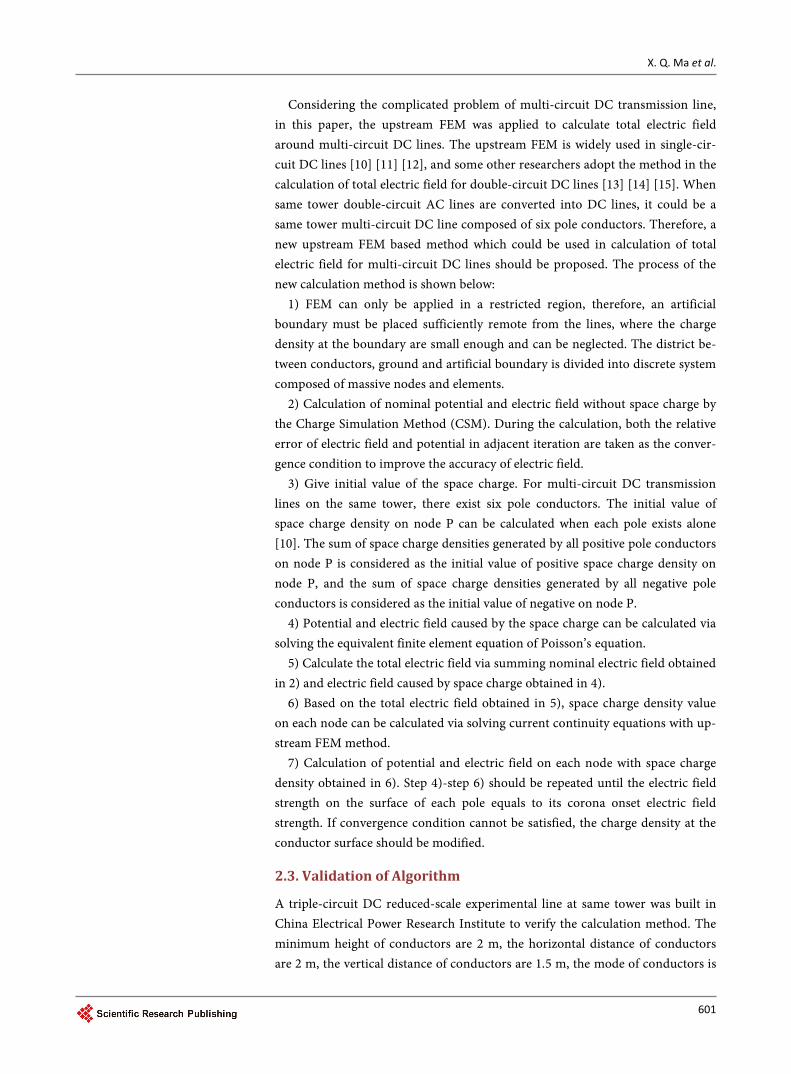
For a DC line converted from a typical same tower double-circuit AC transmis-sion line, there exist seven different pole conductor arrangement schemes, as shown in Figure 1.
2.2. Algorithm Based on Upstream Finite Element Method PV Arrays The equations describing the total electric field of multi-circuit DC transmission lines on the same tower are
( )20ϕ ρ ρ ε+ −∇ = − (1)
( )sk E R eρ ω ρ ρ+ + + −∇ ⋅ + = − (2)
( )sk E R eρ ω ρ ρ− − + −∇ ⋅ − = − (3)
where ϕ is the potential in the presence of space charge, ρ+ and ρ− are positive and negative space charge density, 0ε is permittivity of free space, sE is total electric field in the presence of space charge, k+ and k− are positive and negative ion mobility, ω is wind speed, R is recombination coefficient of positive and negative ions, e is electron charge.
+
+
++
+
+
-
-
-
+
+
+
+
+
+
-
-
-
-
-
-
--
-
(a) scheme a (b) scheme b (c) scheme c (d) scheme d
+
+
-
-
+-
+
-
+
-
+-
+
+
-
--
+
(g) scheme g (e) scheme e (f) scheme f
Figure 1. Pole conductors arrangement schemes.
X. Q. Ma et al.
601
Considering the complicated problem of multi-circuit DC transmission line, in this paper, the upstream FEM was applied to calculate total electric field around multi-circuit DC lines. The upstream FEM is widely used in single-cir- cuit DC lines [10] [11] [12], and some other researchers adopt the method in the calculation of total electric field for double-circuit DC lines [13] [14] [15]. When same tower double-circuit AC lines are converted into DC lines, it could be a same tower multi-circuit DC line composed of six pole conductors. Therefore, a new upstream FEM based method which could be used in calculation of total electric field for multi-circuit DC lines should be proposed. The process of the new calculation method is shown below:
1) FEM can only be applied in a restricted region, therefore, an artificial boundary must be placed sufficiently remote from the lines, where the charge density at the boundary are small enough and can be neglected. The district be-tween conductors, ground and artificial boundary is divided into discrete system composed of massive nodes and elements.
2) Calculation of nominal potential and electric field without space charge by the Charge Simulation Method (CSM). During the calculation, both the relative error of electric field and potential in adjacent iteration are taken as the conver-gence condition to improve the accuracy of electric field.
3) Give initial value of the space charge. For multi-circuit DC transmission lines on the same tower, there exist six pole conductors. The initial value of space charge density on node P can be calculated when each pole exists alone [10]. The sum of space charge densities generated by all positive pole conductors on node P is considered as the initial value of positive space charge density on node P, and the sum of space charge densities generated by all negative pole conductors is considered as the initial value of negative on node P.
4) Potential and electric field caused by the space charge can be calculated via solving the equivalent finite element equation of Poisson’s equation.
5) Calculate the total electric field via summing nominal electric field obtained in 2) and electric field caused by space charge obtained in 4).
6) Based on the total electric field obtained in 5), space charge density value on each node can be calculated via solving current continuity equations with up-stream FEM method.
7) Calculation of potential and electric field on each node with space charge density obtained in 6). Step 4)-step 6) should be repeated until the electric field strength on the surface of each pole equals to its corona onset electric field strength. If convergence condition cannot be satisfied, the charge density at the conductor surface should be modified.
2.3. Validation of Algorithm
A triple-circuit DC reduced-scale experimental line at same tower was built in China Electrical Power Research Institute to verify the calculation method. The minimum height of conductors are 2 m, the horizontal distance of conductors are 2 m, the vertical distance of conductors are 1.5 m, the mode of conductors is
X. Q. Ma et al.
602
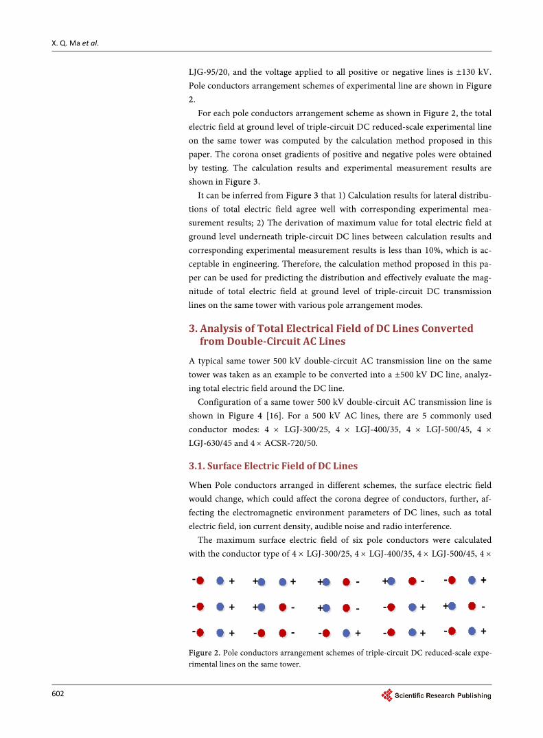
LJG-95/20, and the voltage applied to all positive or negative lines is ±130 kV. Pole conductors arrangement schemes of experimental line are shown in Figure 2.
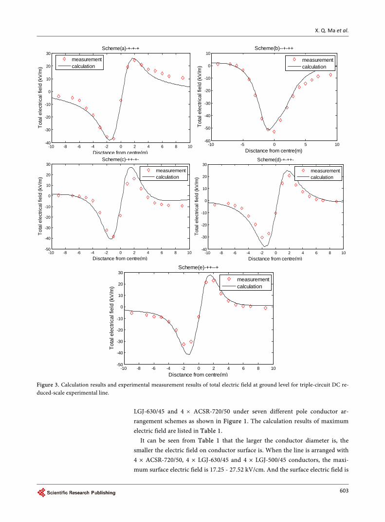
For each pole conductors arrangement scheme as shown in Figure 2, the total electric field at ground level of triple-circuit DC reduced-scale experimental line on the same tower was computed by the calculation method proposed in this paper. The corona onset gradients of positive and negative poles were obtained by testing. The calculation results and experimental measurement results are shown in Figure 3.
It can be inferred from Figure 3 that 1) Calculation results for lateral distribu-tions of total electric field agree well with corresponding experimental mea-surement results; 2) The derivation of maximum value for total electric field at ground level underneath triple-circuit DC lines between calculation results and corresponding experimental measurement results is less than 10%, which is ac-ceptable in engineering. Therefore, the calculation method proposed in this pa-per can be used for predicting the distribution and effectively evaluate the mag-nitude of total electric field at ground level of triple-circuit DC transmission lines on the same tower with various pole arrangement modes.
3. Analysis of Total Electrical Field of DC Lines Converted from Double-Circuit AC Lines
A typical same tower 500 kV double-circuit AC transmission line on the same tower was taken as an example to be converted into a ±500 kV DC line, analyz-ing total electric field around the DC line.
Configuration of a same tower 500 kV double-circuit AC transmission line is shown in Figure 4 [16]. For a 500 kV AC lines, there are 5 commonly used conductor modes: 4 × LGJ-300/25, 4 × LGJ-400/35, 4 × LGJ-500/45, 4 × LGJ-630/45 and 4 × ACSR-720/50.
3.1. Surface Electric Field of DC Lines
When Pole conductors arranged in different schemes, the surface electric field would change, which could affect the corona degree of conductors, further, af-fecting the electromagnetic environment parameters of DC lines, such as total electric field, ion current density, audible noise and radio interference.
The maximum surface electric field of six pole conductors were calculated with the conductor type of 4 × LGJ-300/25, 4 × LGJ-400/35, 4 × LGJ-500/45, 4 ×
+
+
+
-
-
-
+
+
+
-
-
-
+
+
+
-
-
-
+ -
+-
+-
+
+
-
-
-
+-
Figure 2. Pole conductors arrangement schemes of triple-circuit DC reduced-scale expe-rimental lines on the same tower.
X. Q. Ma et al.
603
Figure 3. Calculation results and experimental measurement results of total electric field at ground level for triple-circuit DC re-duced-scale experimental line.
LGJ-630/45 and 4 × ACSR-720/50 under seven different pole conductor ar-rangement schemes as shown in Figure 1. The calculation results of maximum electric field are listed in Table 1.
It can be seen from Table 1 that the larger the conductor diameter is, the smaller the electric field on conductor surface is. When the line is arranged with 4 × ACSR-720/50, 4 × LGJ-630/45 and 4 × LGJ-500/45 conductors, the maxi-mum surface electric field is 17.25 - 27.52 kV/cm. And the surface electric field is
-10 -8 -6 -4 -2 0 2 4 6 8 10-40
-30
-20
-10
0
10
20
30
Disctance from centre(m)
Tota
l ele
ctric
al fi
eld
(kV
/m)
Scheme(a)-+-+-+
measurementcalculation
-10 -5 0 5 10-60
-50
-40
-30
-20
-10
0
10
Disctance from centre(m)
Tota
l ele
ctric
al fi
eld
(kV
/m)
Scheme(b)--+-++
measurementcalculation
-10 -8 -6 -4 -2 0 2 4 6 8 10-50
-40
-30
-20
-10
0
10
20
30
Disctance from centre(m)
Tota
l ele
ctric
al fi
eld
(kV
/m)
Scheme(c)-++-+-
measurementcalculation
-10 -8 -6 -4 -2 0 2 4 6 8 10-40
-30
-20
-10
0
10
20
30
Disctance from centre(m)
Tota
l ele
ctric
al fi
eld
(kV
/m)
Scheme(d)-+-++-
measurementcalculation
-10 -8 -6 -4 -2 0 2 4 6 8 10-50
-40
-30
-20
-10
0
10
20
30
Disctance from centre(m)
Tota
l ele
ctric
al fi
eld
(kV
/m)
Scheme(e)-++--+
measurementcalculation

X. Q. Ma et al.
604
φmm
450 mm
Con 5
Con 4
Con 1 Con 2
H0
Con 3
Con 6
16.4 m
20 m
18.8 m
12 m
10.6 m
Figure 4. Configuration of 500 kV double-circuit AC lines.
Table 1. Maximum surface electric field of DC lines with different conductor types and different pole conductor arrangement schemes.
LGJ-300 LGJ-400 LGJ-500 LGJ-630 ACSR-720
Scheme a 24.42 22.03 20.09 18.32 17.25
Scheme b 30.16 27.24 24.87 22.69 21.38
Scheme c 32.21 29.11 26.59 24.27 22.88
Scheme d 30.27 27.34 24.97 22.78 21.47
Scheme e 33.32 30.12 27.52 25.14 23.70
Scheme f 33.30 30.10 27.50 25.11 23.67
22.03 - 30.12 kV/cm for conductor type 4 × LGJ-400/35, 24.42 - 33.32 kV/cm for conductor type 4 × LGJ-300/25. Ge-Shang, Tian-Guang and Long-Zheng are three typical ±500 DC lines in China, arranged with 4 × 300 mm2, 4 × 400 mm2 and 4 × 720 mm2 conductors respectively. When the pole conductor height is 12.5 m and the horizontal pole conductor distance is 14 m, the maximum sur-face electric field strength of those three typical lines are 28.62, 26.04 and 20.56 kV/cm [17] [18].
It can be seen that when the same tower double-circuit AC line is converted into DC line and arranged as scheme “a”-scheme “g” under the five typical con-ductor type mentioned above, in most cases, the maximum surface electric field is lower than that of typical ±500 kV DC line in China. However, when the con-ductor type is 4 × LGJ-400/35, under conductor arrangement scheme “c”, “e” and “f”, the maximum surface electric field would be slightly above 28.62 kV/cm. And when the conductor type is 4 × LGJ-300/25, only under conductor ar-rangement scheme “a”, the maximum surface electric field would be under 28.62 kV/cm.
3.2. Lateral Distribution of Total Electric Field
The lateral distributions of total electric field at ground level were calculated
X. Q. Ma et al.
605
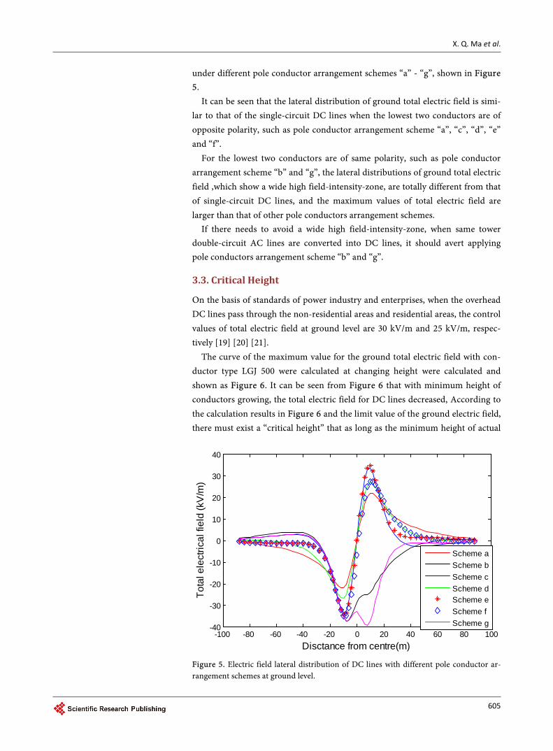
under different pole conductor arrangement schemes “a” - “g”, shown in Figure 5.
It can be seen that the lateral distribution of ground total electric field is simi-lar to that of the single-circuit DC lines when the lowest two conductors are of opposite polarity, such as pole conductor arrangement scheme “a”, “c”, “d”, “e” and “f”.
For the lowest two conductors are of same polarity, such as pole conductor arrangement scheme “b” and “g”, the lateral distributions of ground total electric field ,which show a wide high field-intensity-zone, are totally different from that of single-circuit DC lines, and the maximum values of total electric field are larger than that of other pole conductors arrangement schemes.
If there needs to avoid a wide high field-intensity-zone, when same tower double-circuit AC lines are converted into DC lines, it should avert applying pole conductors arrangement scheme “b” and “g”.
3.3. Critical Height
On the basis of standards of power industry and enterprises, when the overhead DC lines pass through the non-residential areas and residential areas, the control values of total electric field at ground level are 30 kV/m and 25 kV/m, respec-tively [19] [20] [21].
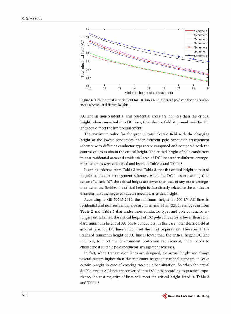
The curve of the maximum value for the ground total electric field with con-ductor type LGJ 500 were calculated at changing height were calculated and shown as Figure 6. It can be seen from Figure 6 that with minimum height of conductors growing, the total electric field for DC lines decreased, According to the calculation results in Figure 6 and the limit value of the ground electric field, there must exist a “critical height” that as long as the minimum height of actual
Figure 5. Electric field lateral distribution of DC lines with different pole conductor ar-rangement schemes at ground level.
-100 -80 -60 -40 -20 0 20 40 60 80 100-40
-30
-20
-10
0
10
20
30
40
Disctance from centre(m)
Tota
l ele
ctric
al fi
eld
(kV
/m)
Scheme aScheme bScheme cScheme dScheme eScheme fScheme g
X. Q. Ma et al.
606
Figure 6. Ground total electric field for DC lines with different pole conductor arrange-ment schemes at different heights. AC line in non-residential and residential areas are not less than the critical height, when converted into DC lines, total electric field at ground level for DC lines could meet the limit requirement.
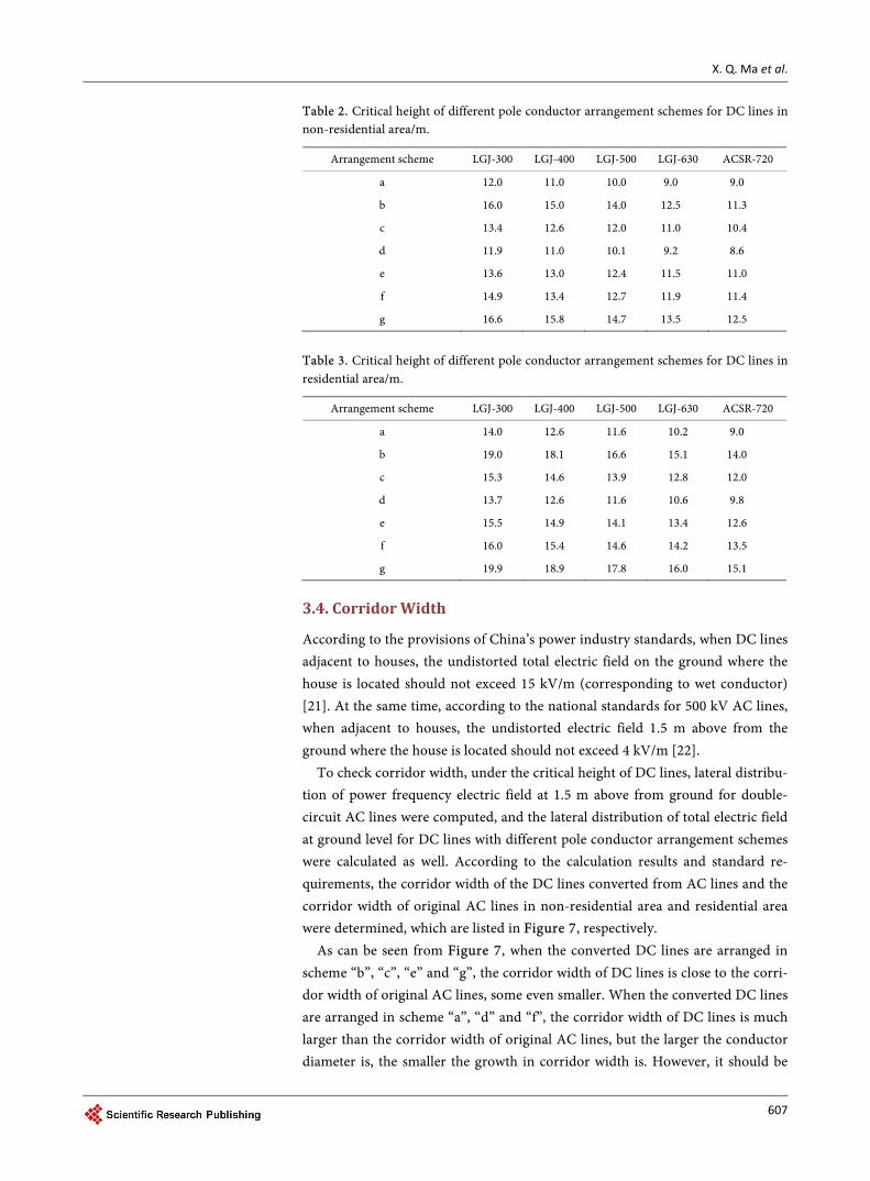
The maximum value for the ground total electric field with the changing height of the lowest conductors under different pole conductor arrangement schemes with different conductor types were computed and compared with the control values to obtain the critical height. The critical height of pole conductors in non-residential area and residential area of DC lines under different arrange-ment schemes were calculated and listed in Table 2 and Table 3.
It can be inferred from Table 2 and Table 3 that the critical height is related to pole conductor arrangement schemes, when the DC lines are arranged as scheme “a” and “d”, the critical height are lower than that of any other arrange-ment schemes. Besides, the critical height is also directly related to the conductor diameter, that the larger conductor need lower critical height.
According to GB 50545-2010, the minimum height for 500 kV AC lines in residential and non-residential area are 11 m and 14 m [22]. It can be seen from Table 2 and Table 3 that under most conductor types and pole conductor ar-rangement schemes, the critical height of DC pole conductor is lower than stan-dard minimum height of AC phase conductors, in this case, total electric field at ground level for DC lines could meet the limit requirement. However, If the standard minimum height of AC line is lower than the critical height DC line required, to meet the environment protection requirement, there needs to choose most suitable pole conductor arrangement schemes.
In fact, when transmission lines are designed, the actual height are always several meters higher than the minimum height in national standard to leave certain margin in case of crossing trees or other situation. So when the actual double-circuit AC lines are converted into DC lines, according to practical expe-rience, the vast majority of lines will meet the critical height listed in Table 2 and Table 3.
11 12 13 14 15 16 17 18 1910
15
20
25
30
35
40
45
Minimum height of conductor(m)
Tota
l ele
ctric
al fi
eld
(kV
/m)
Scheme aScheme bScheme cScheme dScheme eScheme fScheme g
X. Q. Ma et al.
607
Table 2. Critical height of different pole conductor arrangement schemes for DC lines in non-residential area/m.
Arrangement scheme LGJ-300 LGJ-400 LGJ-500 LGJ-630 ACSR-720
a 12.0 11.0 10.0 9.0 9.0
b 16.0 15.0 14.0 12.5 11.3
c 13.4 12.6 12.0 11.0 10.4
d 11.9 11.0 10.1 9.2 8.6
e 13.6 13.0 12.4 11.5 11.0
f 14.9 13.4 12.7 11.9 11.4
g 16.6 15.8 14.7 13.5 12.5
Table 3. Critical height of different pole conductor arrangement schemes for DC lines in residential area/m.
Arrangement scheme LGJ-300 LGJ-400 LGJ-500 LGJ-630 ACSR-720
a 14.0 12.6 11.6 10.2 9.0
b 19.0 18.1 16.6 15.1 14.0
c 15.3 14.6 13.9 12.8 12.0
d 13.7 12.6 11.6 10.6 9.8
e 15.5 14.9 14.1 13.4 12.6
f 16.0 15.4 14.6 14.2 13.5
g 19.9 18.9 17.8 16.0 15.1
3.4. Corridor Width
According to the provisions of China’s power industry standards, when DC lines adjacent to houses, the undistorted total electric field on the ground where the house is located should not exceed 15 kV/m (corresponding to wet conductor)
[21]. At the same time, according to the national standards for 500 kV AC lines, when adjacent to houses, the undistorted electric field 1.5 m above from the ground where the house is located should not exceed 4 kV/m [22].
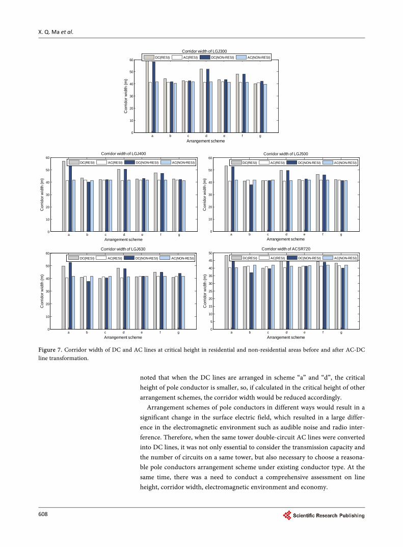
To check corridor width, under the critical height of DC lines, lateral distribu-tion of power frequency electric field at 1.5 m above from ground for double- circuit AC lines were computed, and the lateral distribution of total electric field at ground level for DC lines with different pole conductor arrangement schemes were calculated as well. According to the calculation results and standard re-quirements, the corridor width of the DC lines converted from AC lines and the corridor width of original AC lines in non-residential area and residential area were determined, which are listed in Figure 7, respectively.
As can be seen from Figure 7, when the converted DC lines are arranged in scheme “b”, “c”, “e” and “g”, the corridor width of DC lines is close to the corri-dor width of original AC lines, some even smaller. When the converted DC lines are arranged in scheme “a”, “d” and “f”, the corridor width of DC lines is much larger than the corridor width of original AC lines, but the larger the conductor diameter is, the smaller the growth in corridor width is. However, it should be
X. Q. Ma et al.
608
Figure 7. Corridor width of DC and AC lines at critical height in residential and non-residential areas before and after AC-DC line transformation.
noted that when the DC lines are arranged in scheme “a” and “d”, the critical height of pole conductor is smaller, so, if calculated in the critical height of other arrangement schemes, the corridor width would be reduced accordingly.
Arrangement schemes of pole conductors in different ways would result in a significant change in the surface electric field, which resulted in a large differ-ence in the electromagnetic environment such as audible noise and radio inter-ference. Therefore, when the same tower double-circuit AC lines were converted into DC lines, it was not only essential to consider the transmission capacity and the number of circuits on a same tower, but also necessary to choose a reasona-ble pole conductors arrangement scheme under existing conductor type. At the same time, there was a need to conduct a comprehensive assessment on line height, corridor width, electromagnetic environment and economy.
a b c d e f g0
10
20
30
40
50
60
Arrangement scheme
Cor
ridor
wid
th (m
)
Corridor width of LGJ300
DC(RESI) AC(RESI) DC(NON-RESI) AC(NON-RESI)
a b c d e f g0
10
20
30
40
50
60
Arrangement scheme
Cor
ridor
wid
th (m
)
Corridor width of LGJ400
DC(RESI) AC(RESI) DC(NON-RESI) AC(NON-RESI)
a b c d e f g0
10
20
30
40
50
60
Arrangement scheme
Cor
ridor
wid
th (m
)
Corridor width of LGJ500
DC(RESI) AC(RESI) DC(NON-RESI) AC(NON-RESI)
a b c d e f g0
10
20
30
40
50
60
Arrangement scheme
Cor
ridor
wid
th (m
)
Corridor width of LGJ630
DC(RESI) AC(RESI) DC(NON-RESI) AC(NON-RESI)
a b c d e f g0
5
10
15
20
25
30
35
40
45
50
Arrangement scheme
Cor
ridor
wid
th (m
)
Corridor width of ACSR720
DC(RESI) AC(RESI) DC(NON-RESI) AC(NON-RESI)
X. Q. Ma et al.
609
4. Conclusions
1) When a same tower double-circuit AC line was converted into a DC line, there existed 7 different pole conductor arrangement schemes of same tower triple-circuit DC line.
2) For the first time, the upstream finite element method was extended to the calcu-lation of total electric field for same tower triple-circuit DC line converted from AC line. The experimental results validated the effectiveness of the proposed calculation method in the calculation of total electric field of the same tower triple-circuit DC line.
3) The surface electric field of DC lines converted from AC lines were acceptable which were close to the surface electric field of existing typical DC transmission lines in China.
4) It can be seen that if the lowest two conductors were of same polarity, the lateral distributions of ground total electric field showed a wide high field-in-tensity-zone. If there was necessary to avoid a wide high field-intensity-zone, when same tower double-circuit AC lines were converted into DC lines, it should avert applying pole conductors arrangement scheme “b” and “g”.
5) Under most conductor types and pole conductor arrangement schemes, com-pared to the standard minimum height of original AC line, the critical height of DC pole conductors were sometimes larger, sometimes smaller. In fact, when a transmis-sion line was designed, the actual height was always several meters higher than the standard minimum height to leave certain margin in case of crossing trees or other situation. So when the actual double-circuit AC lines were converted into DC lines, according to practical experience, the vast majority of lines would meet the critical height DC line required.
6) When the converted DC lines were arranged in scheme “b”, “c”, “e” and “g”, the corridor width of DC lines were close to the corridor width of original AC lines, some even smaller. When the converted DC lines were arranged in scheme “a”, “d” and “f”, the corridor width of DC lines were much larger than the corridor width of original AC lines, but the larger the conductor was, the smaller the growth in corridor width was.
7) For 500 kV same tower double-circuit AC lines with common conductors, when the lines were converted into ±500 kV DC lines, total electric field at ground level would meet corresponding standard requirements.
References [1] Xiong, Y.Q. (1993) Transmission line AC-DC conversion. HeiLongjiang Electric Power
Technology, 15, 248-250(in Chinese).
[2] Haeusler, M., Schlayer, G. and Fitterer, G. (1997) Converting AC Power Lines to DC for Higher Transmission Ratings. ABB Review, 4-11.
[3] Orzechowski. (2004) Analysis of Possible Enhancement of Transmission Capacity While Converting 220 kV Alternating Current Overhead Lines into Direct Current Lines. Poland: CIGRE Report B4-105.
[4] Barthold, L.O. (2008) Apparatus and Method for Enhancing the Reconductoring of Over-head Electric Power Lines: USA, 2008/024601.
[5] Wu, J.K., Cao, W. and Yang, W.Q. (2013) Technical Review of Transmission Line AC-DC

X. Q. Ma et al.
610
Conversion. East China Electric Power, 41, 737-740(in Chinese).
[6] Lu, J.Y. and Ju, Y. (2006) Study on the Limits of Electromagnetic Environment of 800 kV
DC Transmission Lines. Electric Power, 39, 37-42(in Chinese).
[7] Hang W.L., Lu, J.Y., Ju, Y., et al. (2007) Design Consideration of Conductor Bundles of 800 kV DC Transmission Lines. Proceedings of the CSEE, 27, 1-6(in Chinese).
[8] Yang, Y., Lu, J.Y. and Lei, Y.Z. (2008) A Calculation Method for the Electric Field under Double-Circuit HVDC Transmission Lines. IEEE Transaction on Power Delivery, 23, 1736-1742.
[9] Yuan, H.W., Yang, Q.H., Liu, Y.Q., et al. (2012) Development and Application of High-Frequency Sensor for Corona Current Measurement under Ultra High-Voltage Di-rect-Current Environment. IEEE Transactions on Instrumentation and Measurement, 61, 1064-1071. https://doi.org/10.1109/TIM.2011.2179337
[10] Takuma, T., Ikeda, T. and Kawamoto, T. Calculation of Ion Flow Fields of HVDC Trans-mission Lines by the Finite Element Method.IEEE Trans on Power Apparatus and System, 100, 4802-4810.https://doi.org/10.1109/TPAS.1981.316432
[11] Takuma, T. and Kawamoto, T. (1987) A Very Stable Calculation Method for Ion Flow Field of HVDC Transmission Lines. IEEE Trans on Power Delivery, 1987, 2,189-198. https://doi.org/10.1109/TPWRD.1987.4308090
[12] Yang, Y., Lu, J.Y. and Ju, Y. (2013) Contrast and Analysis on Total Electric Field at Ground Level under HVDC Transmission Lines by Deutsch Assumption-Based Method And Finite Element Method. Power System Technology, 37, 526-532(in Chinese).
[13] Yang, Y., Lu, J.Y. and Yang, Y. (2012) Calculation of Total Electric Field at the Ground Lev-el under Double-Circuit800 kV DC Transmission Lines Arranged on Same Corridor
with Upstream FEM Method. Power System Technology, 36, 22-27(in Chinese).
[14] Li, W., Zhang, B., He, J.L., et al. (2008) Ion Flow Field Calculation of Multi-Circuit Dc Transmission Lines. High Voltage Engineering, 34, 2719-2725.
[15] Liu, J., Zou, J., Tian, J.H. and Yuan, J.S. Analysis of Electric Field, Ion Flow Density, and Corona Loss of Same-Tower Double-Circuit HVDC Lines Using Improved FEM. IEEE Transactions on Power Delivery, 24, 482-483. https://doi.org/10.1109/TPWRD.2008.2007009
[16] Liu, Z.Y. (2007) Typical Design of Power Transmission and Transformation Project of State Grid Corporation of China: 500 kV Transmission Line (2005). China Electric Power Press, BeiJing.
[17] (1993) High Voltage Transmission Research Center. HVDC Transmission Line Reference Book. USA: High Voltage Transmission Research Center.
[18] Ju, Y., Lu, J.Y. (2006)"Tenth Five-Year" National Science and Technology Research Projects: Research on Environmental Impact of 750 kV, 1 000 kV AC and 800 kV DC System and
Its Application in Engineering (DC Section). China Electrical Power research Institute, Bei-Jing, 2006.
[19] Wu, G.F., Yuan, C.F., Lu, J.Y., et al. (2012) Calculation on Electromagnetic Environment of UHVDC and EHVAC Transmission Lines Erected in a Common Corridor. Power System Technology, 34, 14-19(in Chinese).
[20] Q/GDW 181-2008. Technical Regulation for 500kV DC Overhead Transmission Line
Design.
[21] DL/T 436-2005. Technical Guidelines for HVDC Overhead Transmission Lines.
[22] GB 50545-2010. Technical Guidelines for 110kV~750kV AC Overhead Transmis-sion Line.

Submit or recommend next manuscript to SCIRP and we will provide best service for you:
Accepting pre-submission inquiries through Email, Facebook, LinkedIn, Twitter, etc. A wide selection of journals (inclusive of 9 subjects, more than 200 journals) Providing 24-hour high-quality service User-friendly online submission system Fair and swift peer-review system Efficient typesetting and proofreading procedure Display of the result of downloads and visits, as well as the number of cited articles Maximum dissemination of your research work
Submit your manuscript at: http://papersubmission.scirp.org/ Or contact [email protected]