research paper botball - priawebspace.pria.at/ecer2016/papers/paper_16-0598.pdf · 2016-06-26 ·...
TRANSCRIPT

HTL Saalfelden
Higher college for Mechatronics
Research Paper
SENSORS IN ENGINEERING
Set by: Technical Satisfaction
HTL Saalfelden
Date of submission: March 18th, 2016

HTL Saalfelden
Higher college for Mechatronics
Page| I
SENSORS IN
ENGIN
EERIN
G
ABSTRACT
The aim when writing this research paper was to give the reader a comprehensive as well as
comprehensible insight in the world of sensors used in engineering. Along the next chapters
we will discuss the following points mentioned below.
First of all we will talk about sensors in general, points like “What are sensors?” and
where you can find sensors in everyday life. After that I am going to move to the
classification of sensors.
At the end we will outline different sensor types and explain their technical working
principle.

HTL Saalfelden
Higher college for Mechatronics
Page| II
SENSORS IN
ENGIN
EERIN
G
INTRODUCTION
This research paper of “sensors in engineering“ was written for the robotics competition
called “BOTBALL” that takes place in Vienna in year 2016.
It was created during an interdisciplinary collaboration of the subjects “German” and “FMIT”.
The working paper represents a great opportunity to get into contact with writing scientific
papers as they are needed in my next year of school, which will be my last one too. Even in
later years I will have to do researches and write final papers in case of bachelor- or
master degree course.
The reason why we chose the topic “sensors in engineering” were clear ones: At first,
sensors and actors are replacing mechanical control systems more and more. They are less
complex and much easier to handle, because of the technical progress in electrical and
information industry. It is also a big topic in our professional education to a “Mechatronic
Engineer”. Another reason to choose this topic was, that we are very interested in steering
and controlling processes.
Eventually, I want to give special thanks to our director, Mr. Höller and our supervisor from
school, Mr. Rohm, who made it possible, that we are able to take part at this competition
this year.

HTL Saalfelden
Higher college for Mechatronics
Technical Satisfaction 16-0598 Page| IV
SENSORS IN
ENGIN
EERIN
G
TABLE OF CONTENTS
1 DEFINITION 1
2 SENORS IN EVERYDAY LIFE 1
2.1 SENSORS IN PUBLICITY 1
2.2 SENSORS IN INDUSTRY AND MACHINE ENGINEERING 2
3 CLASSIFICATION OF SENSORS 3
3.1 CLASSIFICATION ACCORDING TO ITS ENERGY SOURCE 3
3.1.1 ACTIVE SENSORS 3
3.1.2 PASSIVE SENSORS 3
3.2 CLASSIFICATION ACCORDING TO MEASURED VARIABLES 4
4 FUNCTIONAL PRINCIPLES OF SENSORS 5
4.1 SENSORS FOR MEASURING DISTANCES AND POSITIONS 5
4.1.1 INDUCTIVE SENSORS 5
4.1.2 CAPACITIVE SENSORS 7
4.1.3 MAGNETIC PROXIMITY SENSORS 8
4.1.4 PHOTOELECTRIC SENSORS 9
4.1.5 ULTRASONIC SENSOR 10
4.2 MOTION SENSORS 11
4.2.1 ACCELERATION AND VIBRATION SENSORS 11
4.2.2 VELOCITY SENSORS 12
4.3 FORCE SENSORS 12
4.3.1 STRAIN-GAUGE SENSORS 13
4.3.2 LOAD CELLS 13
5 SENSORS IN BOTBALL 15
HTL Saalfelden
Higher college for Mechatronics
Technical Satisfaction 16-0598 Page | 1
SENSORS IN
ENGIN
EERIN
G
1 DEFINITION
According to Margaret Rouse, who writes technical articles for many websites on the
World Wide Web, a sensor can be defined as follows:
“A sensor is a device that detects and responds to some type of input from the
physical environment. The specific input could be light, heat, motion, moisture,
pressure, or any one of a great number of other environmental phenomena. The
output is generally a signal that is converted to human-readable display at the
sensor location or transmitted electronically over a network for reading or further
processing.” 1
When talking about sensors, most people immediately think of their sensors in their
smartphone or similar. But sensors have much more skills that anybody could even think
of.
2 SENORS IN EVERYDAY LIFE
2.1 SENSORS IN PUBLICITY
People counteract with sensors every day, they are everywhere. On the way to work there
are sensors e.g. in traffic lights, if the traffic light is steered by traffic. They are in the
touchscreen when buying a ticket at the ticket automat at the railway station. In every
smartphone is a light sensor and much more sensors.
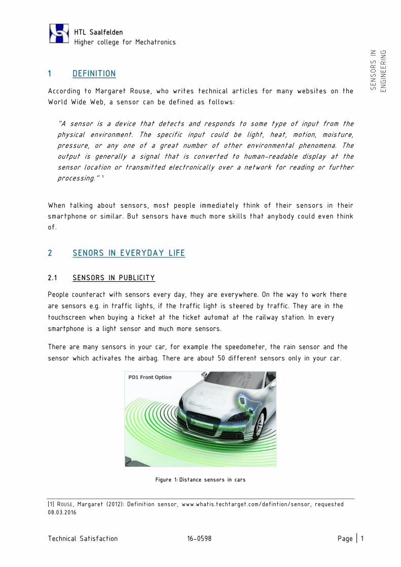
There are many sensors in your car, for example the speedometer, the rain sensor and the
sensor which activates the airbag. There are about 50 different sensors only in your car.
Figure 1: Distance sensors in cars
[1] ROUSE, Margaret (2012): Definition sensor, www.whatis.techtarget.com/defintion/sensor, requested
08.03.2016
HTL Saalfelden
Higher college for Mechatronics
Technical Satisfaction 16-0598 Page | 2
SENSORS IN
ENGIN
EERIN
G
2 .2 SENSORS IN INDUSTRY AND MACHINE ENGINEERING
In Industry, sensors are mainly integrated in production equipment. The provide safety and
enable the intensive production the industry is practising this time.
Without sensors, nearly nothing could be automated as effective as it is possible with
sensors. If there wouldn’t be sensors, everything would have to be automated with
mechanical steering mechanisms. These are very expensive and need a lot of time and
technical Know-How to be developed. This is very time-consuming too. They are very massive
and if there breaks something, it is hard to repair them. In the worst cases, they have to
be completely replaced.
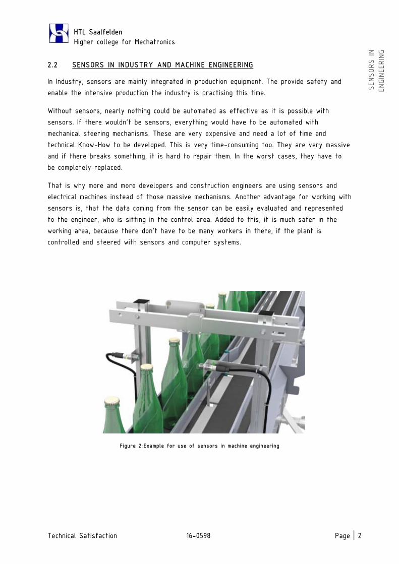
That is why more and more developers and construction engineers are using sensors and
electrical machines instead of those massive mechanisms. Another advantage for working with
sensors is, that the data coming from the sensor can be easily evaluated and represented
to the engineer, who is sitting in the control area. Added to this, it is much safer in the
working area, because there don’t have to be many workers in there, if the plant is
controlled and steered with sensors and computer systems.
Figure 2: Example for use of sensors in machine engineering

HTL Saalfelden
Higher college for Mechatronics
Technical Satisfaction 16-0598 Page | 3
SENSORS IN
ENGIN
EERIN
G
3 CLASSIFICATION OF SENSORS
3.1 CLASSIFICATION ACCORDING TO ITS ENERGY SOURCE
According to their energy source, sensors can be classified as follows:
3.1.1 ACTIVE SENSORS
Active Sensors are producing the energy, which is necessary for transmission, out of the
measure process.
Examples:
thermal element
induction coil
hall-effect probe
pH-electrode
Some of active sensors are producing a electrical variable, which has to be converted
into voltage, to be processed.
Examples:
piezo-crystal
photo-diode
Wiegand-sensor
3.1.2 PASSIVE SENSORS
On passive sensors, energy has to flow through it. The sensor changes his resistance and
modulates a defined variable of this flow of energy. The resistance can be resistive,
capacitive or inductive.
Examples:
resistive:
potentiometer
strain gauge (DMS)
PTC/NTC
photo transistor 2
[2] refer to: MÜLLER, Walter (2010): Sensorgrundlagen,
http://www.ces.karlsruhe.de/culm/culm/culm2/th_messtechnik/sensoren/sensorgrundlagen.pdf,
requested 09.03.2016, p. 3-4

HTL Saalfelden
Higher college for Mechatronics
Technical Satisfaction 16-0598 Page | 4
SENSORS IN
ENGIN
EERIN
G
capacitive: by manipulation of
distance of capacitor plates
the dielectric medium’s retraction depth
inductive: by manipulation of
permeability
cross section
distance of air gap
Sensors with an optical signal output, the light flux can be influenced by:
intensity
frequency
wave length
polarisation
spectral resolution
3.2 CLASSIFICATION ACCORDING TO MEASURED VARIABLES
According to the measured variables, sensors can be classified as follows:
sensors for geometrical variables
sensors for motion quantities
sensors for forces and derived quantities
sensors for hydrostatic and hydrodynamic quantities
sensors for thermometric and calorimetric quantities
sensors for chemical quantities and rates of special substances
sensors for electrical and magnetic quantities
sensors for electromagnetic radiation
sensors for optical quantities
sensors for ionizing radiation 3
[3] refer to: MÜLLER, Walter (2010): Sensorgrundlagen,
http://www.ces.karlsruhe.de/culm/culm/culm2/th_messtechnik/sensoren/sensorgrundlagen.pdf,
requested 09.03.2016, p. 2-3

HTL Saalfelden
Higher college for Mechatronics
Technical Satisfaction 16-0598 Page | 5
SENSORS IN
ENGIN
EERIN
G
4 FUNCTIONAL PRINCIPLES OF SENSORS
4.1 SENSORS FOR MEASURING DISTANCES AND POSITIONS
4.1.1 INDUCTIVE SENSORS
4.1.1.1 Inductive transducer
Principe:
By measuring distance with inductive sensors, you are measuring the change of its
inductance.
The inductance can be changed by a moving iron or ferrite core inside the coil form
(Figure 3a).
“The inductance increases or decreases based on how much the core has moved into
the coil form. These coils are called slug-tuned inductors. Adjustable inductors either
have taps for changing the number of desired turns, or consist of several fixed
inductors that can be switched into various series or parallel combinations (Figure
3b).” 4
Figure 3: (a) An adjustable inductor; (b) a variable inductor
Inductance L:
When current flows in a conducter, it creates a magnetic field and hence magnetic flux
around the circuit. The inductance defines the ratio of the magnetic flux φ [Wb, V*s]
to the current I [A]. 5
The unit of Inductance is Henry (H), named after physicist Josph Henry, born in USA. 6
[4] WINNCY, Y. Du (2015): Resistive, Capacitive, Inductive, and Magnetic Sensor Technologies, CRC Press,
p. 155
[5] refer to: ibid., p. 155
[6] refer to: a.u. (2016): Induktivität, https://de.wikipedia.org/wiki/Induktivit%C3%A4t, requested
10.03.2016

HTL Saalfelden
Higher college for Mechatronics
Technical Satisfaction 16-0598 Page | 6
SENSORS IN
ENGIN
EERIN
G
Figure 4: inductive transducers
4.1.1.2 Inductive Proximity Sensors
Inductive proximity sensors are used for non-contact detection of metallic objects.
Their operating principle is based on a coil and oscillator that creates an electromagnetic
field in the close surroundings of the sensing surface. The presence of a metallic object
(actuator) in the operating area causes a dampening of the oscillation amplitude. The rise or
fall of such oscillation is identified by a threshold circuit that changes the output of the
sensor. The operating distance of the sensor depends on the actuator’s shape and size and
is strictly linked to the nature of the material. 7
Figure 5: inductive proximity sensor
[7] refer to: a.u. (2013): Operating principles for inductive proximity sensors,
http://www.fargocontrols.com/sensors/inductive_op.html, requested 08.03.2016

HTL Saalfelden
Higher college for Mechatronics
Technical Satisfaction 16-0598 Page | 7
SENSORS IN
ENGIN
EERIN
G
4.1.2 CAPACITIVE SENSORS
Capacitive proximity sensors are used for contact-free detection of arbitrary objects.
As contrasted to inductive proximity sensors, which only are able to detect metallic
objects, capacitive sensors can detect non-metallic materials too. Typical application
areas are in the timber, paper, glass, plastics, food and chemical industry. Capacitive
sensors are checking for example in a packaging machine if there are enough cardboards
left as well as the level of the medium inside the cardboard. Another example is the
surveillance of glass or wood plates on a conveyor belt. 9
Principe:
“A capacitor is a passive electrical or electronic component that can store energy
in the form of an electric field. Capacitance, typified ba a parallel-plate arrangement,
is defined in terms of charge storage, where C in the capacitance (In farads, F), Q
is the charge (in coloumb, C) and V is the voltage difference between the two plates
(in volts, V): “ 8
In principle, the capacity of the active electrode of the sensor to ground potential is
measured. An approximated object is affecting this alternating electric field between
this two capacitor plates and its capacity. This affects is caused by metallic as well
as non-metallic objects. The sensitivity of the sensor can be changed with a
potentiometer. 10, 11
Figure 6: capacitive proximity sensors
[8] WINNCY, Y. Du (2015): Resistive, Capacitive, Inductive, and Magnetic Sensor Technologies, CRC Press,
p. 155
[9] refer to: a.u. (2016): Kapazitive Sensoren, http://www.ifm.com/ifmat/web/pinfo010_020_040.htm,
requested 11.03.2016
[10] refer to: ibid., requested 11.02.2016
[11] refer to: a.u. (2013): Operating principles for capacitive proximity sensors,
http://www.fargocontrols.com/sensors/capacitive.html, requested 11.03.2016

HTL Saalfelden
Higher college for Mechatronics
Technical Satisfaction 16-0598 Page | 8
SENSORS IN
ENGIN
EERIN
G
4.1.3 MAGNETIC PROXIMITY SENSORS
4.1.3.1 Hall sensors
Hall sensors operate based on the Hall Effect. A thin sheet of metal or semiconductor
material with a current passing through it is placed in a magnetic field, and then a
voltage is generated perpendicular to the field and the direction of the current flow.
To evaluate their reaction, Hall sensors require amplification and signal conditioning. A
feature of it is, that it is very small and can easily be mounted on diverse surfaces. 12
Hall sensors are widely used in automobile and production industry. There are many
types of Hall sensors. The most common are Hall Position Sensors, Flow Rate Sensors
13
4.1.3.2 Magneto-resistive Sensors
Magnetic sensors are actuated by the presence of a permanent magnet. Their operating
principle is based on the use of reed contacts, which consist of two low reluctance
ferro-magnetic reeds enclosed in glass bulbs containing inert gas. The reciprocal
attraction of both reeds in the presence of a magnetic field, due to magnetic induction,
establishes an electrical contact. 14
Figure 7: scheme of a magnetic sensor
[12] refer to: WINNCY, Y. Du (2015): Resistive, Capacitive, Inductive, and Magnetic Sensor Technologies,
CRC Press, p. 228
[10] refer to: ibid., pp. 234-237
[14] refer to: a.u. (2013): Operating principles for capacitive proximity sensors,
http://www.fargocontrols.com/sensors/magnetic.html, requested 11.03.2016

HTL Saalfelden
Higher college for Mechatronics
Technical Satisfaction 16-0598 Page | 9
SENSORS IN
ENGIN
EERIN
G
4.1.4 PHOTOELECTRIC SENSORS
Photoelectric sensors use light sensitive elements to detect objects and are made up
of an emitter as the light source and a receiver.
Four types of photoelectric reflection are commonly used:
4.1.4.1 Direct Reflection (Diffused)
Emitter and receiver are housed
together and use the light reflected
off the object for detection. In the
use of these photocells, it is
important to bear in mind the color
and the type of surface of the
object. With dark surfaces, the
sensing distance is affected by the
color of the object. Light colors
match to the maximum distances and
vice versa. In the case of shiny
objects, the effect of the surface is
more important than the color. The
sensing distance in the technical data
is related to flat white paper.
Figure 8: different types of photoelectric sensors
4.1.4.2 Reflection with Reflector (Retro-reflective)
Emitter and receiver are in one housing and require a reflector. An object is detected when
it interrupts the light beam between the sensor and reflector. These Photocells allow longer
sensing distances, as the rays emitted are almost totally reflected towards the receiver.
4.1.4.3 Polarized Reflection with Reflector
This type is similar to reflection with Reflector, but these photocells use an anti-
reflex device. The use of such a device, which bases its functioning on a polarized band
of light, offers considerable advantages and secure readings even when the object to
be detected has a very shiny surface. They aren’t affected by any random reflection.
4.1.4.4 Thru Beam
Emitter and receiver are housed separately and detect an object when it interrupts the light
beam between the emitter and receiver. These photocells allow for the longest distances. 15
[15] refer to: a.u. (2012): OPERATING PRINCIPLES FOR PHOTOELECTRIC SENSORS,
http://www.fargocontrols.com/sensors/photo_op.html, requested 11.03.2016

HTL Saalfelden
Higher college for Mechatronics
Technical Satisfaction 16-0598 Page | 10
SENSORS IN
ENGIN
EERIN
G
4.1.5 ULTRASONIC SENSOR
In industrial applications, ultrasonic sensors are characterized by their reliability and
outstanding versatility, Ultrasonic sensors can be used to solve even the most complex
tasks involving object detection or level measurement with millimetre precision, because
their measuring method works reliably und almost all conditions. 16
Two examples of use are surveillance of the maximum filling level of containers or detection
of parts made out of glass (seen in figure 2).
“At manufacturing glass, the place for installation is in most cases very small and
cannot get detection well, caused by the transparency of glass. Most optical Systems
are segregated because of this reasons.” 17
In this special cases, measuring or detecting with ultrasonic sensors is very in common.
Principe:
Ultrasonic sensors are working with a similar principle like photoelectric sensors are
working with.
A special sonic transducer is used for the ultrasonic proximity sensors, which allows
for alternate transmission and reception of sound waves. The sonic waves emitted by
the transducer are reflected by an object and received back in the transducer. After
having emitted the sound waves, the ultrasonic sensor will switch to receive mode. The
time elapsed between emitting and receiving is proportional to the distance of the
object from the sensor.
Figure 9: measuring method of ultrasonic sensors
[16] refer to: a.u. (2016): Ultrasonic Sensors, http://www.pepperl-
fuchs.us/usa/en/classid_182.htm?view=productgroupoverview, requested 11.02.2016
[17] a.u.: Ultrasonic Sensors, automation, 06/2015, p. 26-27

HTL Saalfelden
Higher college for Mechatronics
Technical Satisfaction 16-0598 Page | 11
SENSORS IN
ENGIN
EERIN
G
4.2 MOTION SENSORS
In industry, it is very important to measure the motion quantities, like acceleration,
vibration or velocity in the machine, to get sure, that there are no risks or failures in
the working process.
4.2.1 ACCELERATION AND VIBRATION SENSORS
Acceleration sensors for the measurement of acceleration, shock or vibration come in many
types using different principles of operation.
4.2.1.1 Capacitive Version
Accelerometers that implement capacitive sensing output a voltage dependent on the
distance between two planar surfaces. One or both of these “plates” are charged with
an electrical current. Changing the gap between the plates changes the electrical
capacity of the system, which can be measured as a voltage output. This method of
sensing is known for its high accuracy and stability. Capacitive accelerometers are also
less susceptible to noise and variation with temperature, typically dissipate less power,
and can have larger bandwidths due to internal feedback circuitry.
4.2.1.2 Piezoelectric Version
Inside a piezoelectric version, the sensing element is a crystal, which has the property
of emitting a charge when subjected to a compressive force. In the accelerometer, this
crystal is bonded to a mass such that when the accelerometer is subjected to a ‘g’
force, the mass compresses the crystal which emits a signal. This signal value can be
related to the imposed ‘g’ force.
The sensing element is housed in a suitable sensor body to withstand the environmental
conditions of the particular application. Body are usually made in stainless steel with
welding of the various parts to prevent the ingress of dust, water and other influencing
variables from ambience.
Many present accelerometers have internal electronic circuitry to give outputs which
can be directed used by the associated acquisition or control systems.
Mechanical fixing of the sensor is important in order to achieve true transfer of the
vibration or acceleration. Many fixing methods are used including beeswax, hard glues,
threaded stud or magnetic mounts.
[18] refer to: a.u. (n.d.): The Piezoelectric Accelerometer,
http://www.sensorland.com/HowPage003.html, requested 13.02.2016
[19] refer to: gbarrette (2013): Accelerometer, http://www.sensorwiki.org/doku.php/sensors/accelerometer,
requested 13.03.2016
HTL Saalfelden
Higher college for Mechatronics
Technical Satisfaction 16-0598 Page | 12
SENSORS IN
ENGIN
EERIN
G
4.2.2 VELOCITY SENSORS
Piezo-Velocity (PVT) sensors are solid state piezoelectric velocity measurement devices.
They are essentially accelerometers with an internal integration circuit which will
produce an output relative velocity. Many vibration analysts prefer to examine vibration
signals in terms of velocity to amplify the signal of interest. PVT sensors basically
decrease high frequency signals allowing better measurement of low frequency vibration.
PVTs can reduce signal noise in many low frequency measurements. The integration
circuit amplifies low frequency signals and attenuates high frequency signals. This
increases the voltage output at low frequency and filters high frequency noise. The
increase in low frequency voltage output reduces the noise contribution of the
acquisition equipment. The inherent filtering reduces intermodulation distortion caused
when high frequency signals overload the amplifier and may reduce the "ski slope"
noise in many applications. 20
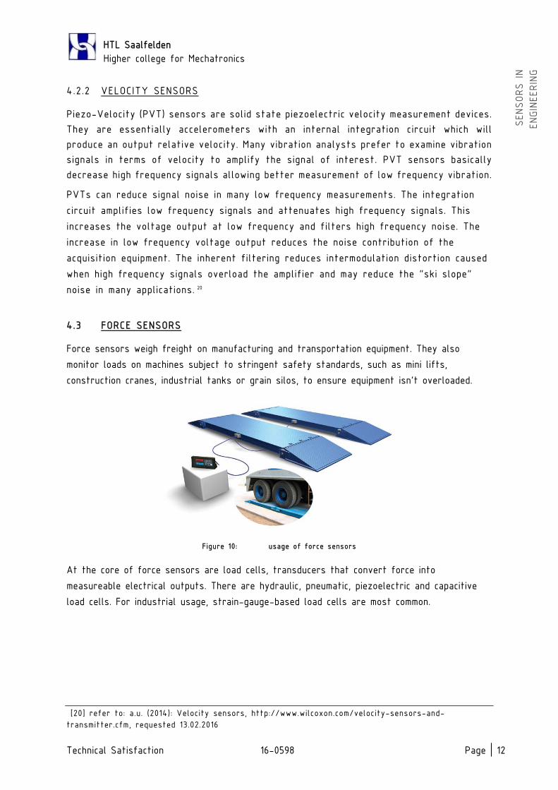
4.3 FORCE SENSORS
Force sensors weigh freight on manufacturing and transportation equipment. They also
monitor loads on machines subject to stringent safety standards, such as mini lifts,
construction cranes, industrial tanks or grain silos, to ensure equipment isn’t overloaded.
Figure 10: usage of force sensors
At the core of force sensors are load cells, transducers that convert force into
measureable electrical outputs. There are hydraulic, pneumatic, piezoelectric and capacitive
load cells. For industrial usage, strain-gauge-based load cells are most common.
[20] refer to: a.u. (2014): Velocity sensors, http://www.wilcoxon.com/velocity-sensors-and-
transmitter.cfm, requested 13.02.2016

HTL Saalfelden
Higher college for Mechatronics
Technical Satisfaction 16-0598 Page | 13
SENSORS IN
ENGIN
EERIN
G
4.3.1 STRAIN-GAUGE SENSORS
The most common force sensors based on strain gauges are load pins, shear beams and
tension links
4.3.1.1 Tension links
Tension links, also called a tension cells, consist of two steel padeyes and a center
body housing the load cell. They measure the force in cables, chains, and pulleys, and
are most common in lifting, pulling, and winching applications on cranes and wire
tensioners on safety cages used in mines. Standard tension links measure 11000 to
45000 kilograms, though custom versions can measure more.
4.3.1.2 Load pins
Load pins are used to measure occurring shear forces. Typically, a beam is machined to
be almost completely hollow save for one segment with a solid cross section. Sensing
elements mounted on this remaining wall of material (called web). The tubular body of
the load pin withstands bending stresses while the solid cross section withstands
vertical and horizontal shear stresses. The web’s strain gauges measure these shear
stresses. Standard capacities exceed 9000 kg, though custom pins go higher.
4.3.1.3 Shear beams
Just like load pins shear beams measure shear forces. There are Single-ended shear
beams and double-ended shear beams. Single-ended are cantilevered sensors which load
is applied at the free, double-ended ones are supported at both ends where the load
is in the centre. Single ended shear beams weigh loads in blenders, hoppers and floor
scales. Double ended shear beams weigh tanks and items and large capacity platforms.
Both shear beams detect loads to 18000 kg in 10 to 20 kg steps. 21
4.3.2 LOAD CELLS
A load cell is a device that is used to convert a force into electric signal. Strain gauge
load cells are the most common types of load cells. There are other types of load cells
such as hydraulic load cells, pneumatic load cells, piezoelectric load cells or capacitive
load cells.
Load cells are used for quick and precise measurements. Compared with other sensors,
load cells are relatively more affordable and have a longer life span.
[21] refer to: WILLIAMS, Del (2013): Force sensors and their uses,
http://machinedesign.com/sensors/force-sensors-and-their-uses, requested 13.02.2016

HTL Saalfelden
Higher college for Mechatronics
Technical Satisfaction 16-0598 Page | 14
SENSORS IN
ENGIN
EERIN
G
4.3.2.1 Strain Gauge load cells
The principle of operation of the Strain Gauge is based on the fact that the resistance
of the electrical conductor used in strain gauge construction changes when its length
changes due to stress.
A load cell usually consists of four strain gauges in a Wheatstone bridge configuration.
The electrical signal output is typically very small in the order of a few mV. It is
amplified by an instrumentation amplifier before sending it to the measurement system.
4.3.2.2 Capacitive load cells
Capacitive load cells are based on the principle where the capacity of a capacitor
changes as the load presses the two plates of a capacitor closer together. The
construction of a capacitive sensor is simpler than a resistive load cell.
4.3.2.3 Hydraulic load cells
Hydraulic load cells are force-balance devices, measuring weight as a change in loading
head is transferred to a piston that in turn compresses a filling fluid confined within
an elastomeric membrane chamber. As the force increases, the pressure of the hydraulic
fluid increases. This pressure can be locally indicated or transmitted for remote
indication or control. This sensor has no electric components and immune to transient
voltages so it’s ideal for use in hazardous areas. The disadvantages of hydraulic load
cells are, that they are very expensive and complex.
4.3.2.4 Pneumatic load cells
Pneumatic load cells operate on the force-balance principle. These devices use cushion
chambers to provide higher accuracy than a hydraulic device. Pneumatic load cells are
often used to measure relatively small weights in industry where cleanness and security
are of prime concern. 22
Figure 11: hydraulic load cell
[22] refer to: SHUKLA, Vinaykumar (2013): Load cell working, types, advantages and disadvantages,
http://www.instrumentationengineers.org/2013/07/load-cell-working-types-advantages-and.html,
requested 13.02.2016
HTL Saalfelden
Higher college for Mechatronics
Technical Satisfaction 16-0598 Page | 15
SENSORS IN
ENGIN
EERIN
G
5 SENSORS IN BOTBALL
The sensors which are included in our BOTBALL-set are primarily Photoelectric Sensors,
e.g. ET, Tophat as well as Photodiodes and resistive sensors like the linear slide.
I would recommend some other types of sensors for future competitions. This would
be capacitive sensors instead of touch and lever sensors, because they are easily
breaking down. Another improved solution would be to ETs through ultrasonic sensors,
because they are much more reliable than ETs.

HTL Saalfelden
Higher college for Mechatronics
Technical Satisfaction 16-0598 Page | V
SENSORS IN
ENGIN
EERIN
G
BIBLIOGRAPHY
http://machinedesign.com/sensors/force-sensors-and-their-uses
http://www.fargocontrols.com
http://www.ifm.com
http://www.instrumentationengineers.org
http://www.pepperl-fuchs.us/usa/en
http://www.sensorland.com
http://www.sensorwiki.org
http://www.wilcoxon.com/velocity-sensors-and-transmitter.cfm
https://de.wikipedia.org/wiki/Induktivit%C3%A4t
MÜLLER, Walter (2010): Sensorgrundlagen,
http://www.ces.karlsruhe.de/culm/culm/culm2/th_messtechnik/sensoren/sensorgru
ndlagen.pdf
ROUSE, Margaret (2012): Definition sensor,
www.whatis.techtarget.com/defintion/sensor
Ultrasonic Sensors, automation
WINNCY, Y. Du (2015): Resistive, Capacitive, Inductive, and Magnetic Sensor
Technologies, CRC Press

HTL Saalfelden
Higher college for Mechatronics
Technical Satisfaction 16-0598 Page | VI
SENSORS IN
ENGIN
EERIN
G
LIST OF FIGURES
Figure 1: Distance sensors in cars 1
Figure 2: Example for use of sensors in machine engineering 2
Figure 3: (a) An adjustable inductor; (b) a variable inductor 5
Figure 4: inductive transducers 6
Figure 5: inductive proximity sensor 6
Figure 6: capacitive proximity sensors 7
Figure 7: scheme of a magnetic sensor 8
Figure 8: different types of photoelectric sensors 9
Figure 9: measuring method of ultrasonic sensors 10
Figure 10: usage of force sensors 12
Figure 11: hydraulic load cell 14

HTL Saalfelden
Higher college for Mechatronics
Technical Satisfaction 16-0598 Page | VII
SENSORS IN
ENGIN
EERIN
G
SOURCES OF FIGURES
Figure 1: www.parkingdynamics.co.uk
Figure 2: www.optex-fa.com
Figure 3: WINNCY, Y. Du (2015): Resistive, Capacitive, Inductive, and Magnetic
Sensor Technologies, CRC Press, p. 155
Figure 4: www.schreiber-messtechnik.de
Figure 5: www.omega.com
Figure 6: http://www.fargocontrols.com
Figure 7: www.newark.com
Figure 8: http://www.fargocontrols.com
Figure 9: http://www.baumer.com/
Figure 10: machinedesign.com
Figure 11: instrumentationandcontrollers.blogspot.com
Figure on cover sheet: http://www.directindustry.de/prod/telco-sensors/