research report 374 - health and safety executive · evaluating the effectiveness of legislation,...
TRANSCRIPT

HSEHealth & Safety
Executive
Evaluating the effectiveness of legislation,technology and working methods for reducingoccupational exposure in the foundry industry
Prepared by Castings Technology International for the Health and Safety Executive 2005
RESEARCH REPORT 374

HSEHealth & Safety
Executive
Evaluating the effectiveness of legislation,technology and working methods for reducingoccupational exposure in the foundry industry
D WELLS B.Sc,C.Chem, MRSC, M.Sc, Dip.Occ.Hyg, MFOH
A GREENALL B.Sc, M.Sc, AIEMA
Castings Technology InternationalBordersley Hall
AlvechurchBirmingham B48 7QB
The project arose from the Health and Safety Executive’s (HSE) Competition of Ideas Initiative andwas designed to exploit the wealth of historical dust, fume, and gas occupational exposure monitoringdata available in Castings Technology International’s (Cti’s) archives. The project enabled theextraction of over 50,000 data points from hard copy archived reports and transfer to an electronicanalysable database, and sought to provide an insight into the effects of legislation, sector guidance,technology and working methods on the reduction of occupational exposure in the UK foundry industry.
The results demonstrated that the Health and Safety at Work, etc, Act (HASAWA) and Control ofSubstances Hazardous to Health Regulations (COSHH) together with Cti and its predecessors’proactive approach had profound beneficial effects on exposure. Examination of the database alsoexplored other influences on exposure and relationships between various subsets. It also providedexposure statistics to inform exposure limit setting and raised issues of interest to the occupationalhygiene community.
This report and the work it describes were funded by the Health and Safety Executive. Its contents,including any opinions and/or conclusions expressed, are those of the authors alone and do notnecessarily reflect HSE policy.
This report makes reference to work carried out by Dr John Thompson that was also funded by HSE.That work is published as Research Report 373 (2005) Development of Statistical Approaches to the Handling and Analysing of Large Occupational Data Sets.
HSE BOOKS

ii
© Crown copyright 2005
First published 2005
ISBN 0 7176 6151 2
All rights reserved. No part of this publication may bereproduced, stored in a retrieval system, or transmitted inany form or by any means (electronic, mechanical,photocopying, recording or otherwise) without the priorwritten permission of the copyright owner.
Applications for reproduction should be made in writing to: Licensing Division, Her Majesty's Stationery Office, St Clements House, 2-16 Colegate, Norwich NR3 1BQ or by e-mail to [email protected]

ACKNOWLEDGEMENTS The authors wish to thank other members of staff at Cti who assisted in the preparation of this report, notably: • Mrs C A Davis For staying sane while entering most of the data and also for more
conventional secretarial assistance.
• Ms S Armstrong For entering data.
• Dr J G Morley For managing the project.
• Mr F M Shaw (retired)
For stretching his memory to provide much peripheral data on foundry sites now closed.
• Mr C Mills For organising despatch of Sheffield files and providing background data.
• and others who helped with brainstorming sessions. We would also like to thank Dr A Phillips and Dr C Elliott-Minty from HSE for their encouragement and help throughout the project. Special thanks should go to Dr J M Thompson who has tried hard to get us up to speed on basic exploratory statistics both by dedicated training sessions and a “help line” service. Nevertheless, any failures remain our own. Dr Thompson is a professional statistician specialising in exploratory statistics who was contracted by HSE partly to provide some support for the project presented in this report, but mainly to carry out a parallel but associated project on how best to handle data sets such as ours. There could well be advantages in reading our report in conjunction with his, as he will cover aspects, such as the justifications for using the techniques we have used and also ways of establishing confidence limits, which we have been unable to present.
iii

iv

CONTENTS
EXECUTIVE SUMMARY 1 CHAPTER 1 INTRODUCTION 3 CHAPTER 2 METHODOLOGY OF DATA ENTRY AND ANALYSIS 7
2.1 Introduction 7 2.2 Data extraction and input 8 2.3 Data conventions 9 2.4 Data checking 112.5 Hypotheses 112.6 Strategy 112.7 Data analysis 112.8 Preparation of data for export 122.9 Statistical analysis 13
CHAPTER 3 OUTCOMES - LEGISLATION ISSUES 173.1 Legislation as driver 17
3.1.1 The effects of HASAWA and COSHH 17 3.1.2 The effects of other legislative changes 23
3.2 Relationships between various data subsets and the influences on exposure 26 3.2.1 The effect of commitment 26 3.2.2 Effect of foundry type (steel or iron) and size on exposure 28 3.2.3 Mutual validation of NEDB/Cti foundry data 30 3.2.4 Comparisons of Alvechurch and Sheffield data 32
3.3 Use of data to inform 33 3.3.1 Silica exposure statistics 34 3.3.2 Formaldehyde exposures 34 3.3.3 Furfuryl alcohol exposures 35 3.3.4 Manganese 36 3.3.5 Nickel 36
3.4 Relationships between different data subsets for information 37 3.4.1 Relationships between respirable silica and respirable dust 38 3.4.2 Relationships between total metals (fume content) and iron (for ferrous
foundries), and with total dust 42
3.4.3 Use of static samples to estimate personal exposure 44 3.4.4 The relationship between ammonia and amine sampling 46
CHAPTER 4 MATTERS ARISING 494.1 The dangers of “Black Box” analysis 494.2 An appropriate sampling method must not only work but have adequate
sensitivity 50
4.3 Reporting 534.4 NEDB data entry 544.5 Total dust estimation using a cyclone sampler 554.6 Cristobalite in foundries 56
CHAPTER 5 SUMMARY OF OUTCOMES 59CHAPTER 6 RECOMMENDATIONS FOR FURTHER WORK/ACTIONS 61
v

APPENDIX 1 HYPOTHESES TO CONSIDER 63APPENDIX 2 HISTORIC DATA PROJECT - ANALYTICAL TIME LINE 65APPENDIX 3 FACTORS INFLUENCING PERSONAL EXPOSURES IN FOUNDRIES 67APPENDIX 4 DATABASE SUMMARY 73APPENDIX 5 USEFUL JOB GROUPINGS 79APPENDIX 6 PIVOT TABLES 81 BIBLIOGRAPHY AND REFERENCES 85 GLOSSARY OF FOUNDRY TERMS 87 ABBREVIATIONS 89
vi

EXECUTIVE SUMMARY
This project was set up to take advantage of the fact that Castings Technology International (Cti), and its predecessor organisations have been undertaking monitoring for substances hazardous to health within the foundry sector since the 1960’s. Although much of the resulting exposure data has been lost through normal reorganisation and “clear-outs”, a substantial amount of data remains in archived hard copy. The project enabled the data to be extracted and transferred from hard copy to an electronic analysable form (a Microsoft EXCEL spreadsheet). This took a considerable amount of effort (from June 2003 to July 2004). Once the data was verified and available in spreadsheet form, data analysis was undertaken, in order to provide a picture, not only of current exposures, but also how they have changed over the years. Where changes had occurred, attempts have been made to link these with the factors which influenced the exposure change. The analysis reported herein was far ranging and aimed at revealing major issues which had been formulated as a set of hypotheses at an early stage of the project. It mainly considers changes in the bulk of the data and only a limited amount of sub-division has been undertaken. In particular changes in extreme values have not generally been addressed. The project has only allowed a fairly superficial analysis of this large amount of data, with a steep learning curve in determining appropriate techniques to handle such a database. Much further analysis would be valuable, both to enable Cti to inform the foundry sector and to inform the Health and Safety Executive (HSE) of general occupational hygiene issues using the foundry sector as an example. A number of recommendations for further work have been made. The database consists of about 50,000 data points, the majority of which relate to dusts and their components, although there is also substantial data on exposures to a wide range of gaseous and vapour phase pollutants. Probably the most important finding was that, at least in the foundry sector, the introduction of the Health and Safety at Work, etc, Act (HASAWA) and Control of Substances Hazardous to Health Regulations (COSHH) initiated or catalysed programmes of improvement in engineering control, mainly Local Exhaust Ventilation (LEV), in areas where control was clearly inadequate. This improvement has generally continued to the present as a greater proportion of the remaining foundries are using best practice. Not only is greater monitoring activity demonstrated immediately following the introduction of HASAWA and COSHH, but also, where engineering control needed to be applied, a sustained improvement in that control has been shown. By contrast, where exposures were considered satisfactory with minimal or no control, as expected there was little change with time. However, where changes to exposure limits have made previously acceptable levels unacceptable, there is some evidence that the change has initiated a further round of control improvement, e.g. amine at cold box coremaking for which the Occupational Exposure Standard (OES) was reduced from 10 → 2 ppm in 2002, although this change was too recent to be fully conclusive. The introduction of the silica Maximum Exposure Limit (MEL) did not obviously change the downward trend in exposure, although the withdrawal of the Sector Guidance at the time of the MEL review and adoption of the Comite Europeen de Normalisation (CEN) respirable dust convention in 1997 was probably a mistake, allowing a slight relaxation of control. Similarly,
1

the introduction of the Ferrous Foundry Particulate (FFP) MELs did not appear to significantly change the trends. The Environmental Protection Act 1990 had mixed effects. Process Guidance aimed at reducing fugitive emissions has been shown to have helped to reduce exposures to magnesium fume at Spheroidal Graphite (SG) treatment for example. On the other hand the requirements for regular emission testing have seriously reduced the uptake of new “desirable” LEV, as opposed to necessary LEV, which is why there has been little improvement in control at melting. Exposures have generally been at least acceptable except where high alloys involving toxic metals are involved and extraction is then provided. Other influences on exposure were also explored. These were generally superimposed on the trends initiated by HASAWA and COSHH. The effects of foundry characteristics such as attitude to health and safety, metal melted, and size were shown to be significant although not always great. It could also be shown that the data sets from the two Cti sites and the National Exposure Data Base (NEDB) foundry set were not obviously from different populations. The other major outcome expected from this project was the ability to use this data base to inform, both the standard setting process (in terms of achievable levels of key pollutants) and the monitoring agencies, including Cti, (in terms of relationships between various data subsets). Post-1998 data on silica exposures were provided for the Regulatory Impact Assessment (RIA) for the proposed silica Workplace Exposure Limit (WEL) and exposure statistics are presented for other analytes of topical interest. In the cases of furfuryl alcohol and nickel, recent trends in exposures and their causes have pointed toward the need for improved control and indicated possible strategies for achieving this. Relationships between several subsets were explored with a view to assessing how well one could be used to predict another, or to establishing likely ranges of, for example, silica content of respirable dust for various types of operation, to provide an extra check on whether data obtained in subsequent monitoring are reasonable or should be queried. In one instance a change in relationship with time provided an indicator of change in foundry processes and hence where control efforts should be concentrated. Finally, in the course of investigating the data base, several instances of unexpected or unusual data distributions were discovered, which needed investigation to allow proper handling of the data. These investigations revealed several issues of importance to the wider occupational hygiene community and/or foundries, and are presented in Chapter 4 for one of two reasons. In some cases Cti would hope that other agencies would be able to learn from our experience, as we have, and take appropriate action. In others, questions of practice have arisen which need rational public debate and full published scientific validation (or invalidation) in order to set properly justified standards of practice. Recommendations for further work are made in Chapter 6. These include a group of actions to be taken by, or of interest to, the wider occupational hygiene sector and generally resulting from sections in Chapters 3 and 4. A further group of actions, largely to be taken by Cti, and mainly in order to clarify incomplete explanations of trends demonstrated in this project, is also included. Some of the items in the first group in particular may justify further funding from the HSE.
2

CHAPTER 1
INTRODUCTION This project arose from an idea submitted to the Health and Safety Executive (HSE) in May 2002 as part of the Competition of Ideas Initiative and was designed to exploit the wealth of historical dust, fume and gas monitoring data available in Castings Technology International’s (Cti’s) archives. The project seeks to provide an insight into the effects of legislation, sector guidance, technology and working methods on the reduction of occupational exposures in the UK foundry industry. Cti is a Membership based organisation providing technical support to the foundry industry, or at least that part which is in Membership. For many years support has been and is offered in all aspects of foundry operation. The Environmental Section specialises in measurement and control advice in the fields of internal and external environment, including occupational hygiene monitoring, stack emission monitoring and contaminated land assessment. This report concerns the analysis of results arising from occupational hygiene monitoring of dusts, fumes and toxic gases (Control of Substances Hazardous to Health Regulations (COSHH) monitoring). Cti was created out of a merger in 1996 of the research associations for the cast iron and steel casting industries, BCIRA and SCRATA respectively. These were formerly supported by Government levy but became much more commercial when that levy ceased. The two sites, at Alvechurch, Birmingham (formerly BCIRA) and at Sheffield (formerly SCRATA) were both maintained after the merger. The present organisation and its predecessors have been proactively involved in promoting health and safety within the foundry industry and have offered occupational hygiene monitoring services from the mid 1960’s onwards. Pioneering work in occupational hygiene took place within these organisations. The first personal cyclone sampler, a device to differentiate between fractions of respirable and inhalable dust, was invented within BCIRA by Messrs R Higgins and P Dewell in 1968 and developed commercially initially by Casella. Modified versions of this cyclone without the original cowl, incorporating a cassette for the respirable dust filter, detachable rubber grit pot and a tubular air inlet were introduced later by various suppliers, although the original version was still available commercially until very recently. Historically the two organisations had different approaches to their occupational hygiene monitoring services. BCIRA offered a more research orientated approach with professional qualified hygienists (Diploma level) backed up by professional chemists and engineers. Monitoring was often on particular problem areas either identified by the client or by BCIRA and the aim was always to provide detailed advice on specific control measures for those problems. In the past the engineering function provided nuts and bolts level design services and/or actual hardware, but this aspect ceased in the early 1990’s. However, the general approach is still followed. Until 2001 an in-house laboratory provided analysis of environmental samples (and developed foundry specific methods for many analytes). The original cowled cyclone has been, and still is, used from the Alvechurch site with x-ray diffraction (XRD) analysis for respirable silica, initially in-house but using a contract laboratory from 2002. SCRATA at Sheffield mainly offered a system of routine annual monitoring carried out at technician level (P-cert/module). This often combined COSHH monitoring with noise
3

monitoring and Local Exhaust Ventilation (LEV) testing. Assessment has been mainly on the basis of compliance versus non-compliance, with basic advice such as “Appropriate Respiratory protective equipment (RPE) such as X or Y should be worn in this area” or “LEV should be introduced/improved/used properly in this area” or ‘’Working practice A is poor and should be changed to B’’, given for non-compliant situations. Respirable silica is determined in-house by Fourier transform infra red (FTIR) (Infra red (IR) until 1992) together with gravimetric analysis for the total and respirable fractions of dust. There are limited chemical analysis facilities at the Sheffield site so traditionally there has been a high reliance on indicator tubes (mostly diffusive) for vapours and gases. Some analytes have always been determined using a contract laboratory and recently more analytes have been sent for contract analysis. SIMPEDS type cyclones have been used for the whole period for which data are available. United Kingdom Accreditation Service (UKAS) accreditation was obtained for most routine sampling in early to mid 1990’s. Both sites have endeavoured to ensure that methodologies were sound but BCIRA’s technical back-up usually meant that unsuitable methods were picked up more quickly. At the time of the merger there was clearly more interaction between the two sites, but there was no direct line management liaison so the general approaches remained unchanged. Identified problems at Sheffield were referred to Alvechurch for occupational hygiene or chemical advice, but some problems were not identified as such. Following the closure of the Alvechurch laboratory in October 2001 both sites used the same sampling media and analytical methods for most substances, the main exception being silica. Both approaches to monitoring had appeal to our Members, although the Sheffield approach, being much cheaper and probably more typical of many organisations offering COSHH monitoring services, was more economically viable, hence the relatively larger amount of data generated from this site. Both organisations have large amounts of historic monitoring data, but it was kept as text in hard copy survey reports and therefore not easy to search or analyse. Much was also as coloured carbon copies and could not even be scanned. Nevertheless it was felt that this accumulation of data was a valuable resource and so this project was established to allow the data to be transformed into a searchable electronic form. It could then be examined for any trends which could be identified and correlated with legislative or other influences. The methodology used for transferring and examining the data is presented in the next chapter. Alvechurch has data from the early 1970’s to the present, although many individual company files have been lost. Sheffield now only has data from about 1985 to the present. Because data have been entered company by company there is no definite cut-off date. For the purposes of this project, exposure data were entered into an electronic data base over the period June 2003 to July 2004. The data base consists of 51472 points, 48037 of which relate to foundries and closely allied industries such as forging, machining etc. The biggest single data set is triads of Total Dust (TD), Respirable Dust (RD) and Respirable Silica (RS). Further details of the data base are given in Appendix 4. This report presents the results of initial analysis of the data carried out between July 2004 and October 2004, which in many cases point to further lines of enquiry and/or uses. The analytical techniques used have been developed during the course of the project and lean heavily towards descriptive and exploratory statistics. Descriptive statistics allow trends to be shown simply,
4

although with an element of subjectivity. Although several different types of relationship amongst the data have been explored (see hypotheses – Appendix 1), the main objective of this project was to identify trends in and, possibly, associated influences on, health and safety in foundries, and in particular exposures to various chemicals. Where appropriate, professional judgement and experience of the industry has been used to aid interpretation of the findings. The project consisted of three main stages: • Transfer of data from hard copy reports to a Microsoft Excel spreadsheet, which has been
used as a database. All subsequent references to database(s) refer to data held on Excel spreadsheets.
• Analysis of the data, using largely distribution free methods (under the tutelage of Dr J M
Thompson). • Presentation of the outcomes resulting from this analysis.
5

6

CHAPTER 2 METHODOLOGIES OF DATA ENTRY AND ANALYSIS
2.1 INTRODUCTION The project involved two distinct processes: • data extraction and input • data analysis The data extraction and input involved the manual extraction of results from archived files dating back to the 1970s and the inputting of these raw data onto a computer based spreadsheet. Data analysis involved using these data to explore various hypotheses formulated before, and to some extent during, the process of statistical data exploration. This process was iterative whereby the hypotheses were revisited throughout the project. This process is summarised in Figure 2.1.
Formulation of initial hypotheses
Extraction of raw data
Input of data in electronic form
Generation of NEDB type database Dat
a ex
tract
ion
Data verification/standardisation
* Review of analysis programme
Data preparation
Transfer to analytical software
Dat
a an
alys
is
Statistical analysis
Data interpretation
Dat
a pr
esen
tatio
n
Presentation
* Iterative process – the initial hypotheses were investigated firstly and the programme revised as data was explored
Figure 2.1: Formulation of initial hypotheses - flow diagram of project
The data handling was undertaken using Microsoft Excel 2002, and statistical analysis using Minitab version 14 on a desktop PC running on Windows XP 2002 and using Microsoft Office XP.
7

2.2 DATA EXTRACTION AND INPUT Existing HSE exposure data are currently stored within the National Exposure Database (NEDB). To allow some degree of compatibility with existing HSE/NEDB data an Excel spreadsheet NEDB pro-forma was provided by HSE. This was used to structure the database. Following some initial exploration, five additional columns to the 23 required by NEDB were added for the purposes of this project, the first of which was simply an assigned row number; row one of the Excel generated sheet shows column descriptors so the two row numbers differ by one (see Figure 2.2). The other four additional columns will be explained later (see Figure 2.3). The basic data source was the results tables from archived survey reports. For some, work sheets were also available, and sometimes additional information was available from the text of the reports. Otherwise peripheral information desired by NEDB was determined from our own knowledge of the sites concerned and the methodology used. At this entry stage all available data, including that indicated as unreliable by the monitoring hygienist, was entered on the basis that analysis during this project would provide an objective means of rejecting such data.
Figure 2.2: Screen capture of part of a typical data table showing assigned row numbers in column A
8

The NEDB pro-forma was used to generate a series of hard copy, row numbered, pro-formas. Information was extracted and hand entered to complete the pro-formas, report by report, and customer file by customer file. Batches of these hard copies were passed to a copy typist for entering the data into the equivalent electronic pro-forma to produce batch “raw data” files. These files were then checked (and corrected) against the hard copy data for accuracy and consistency by the experienced extractor to give batch “checked” files. The checked files were then pasted into a master, password protected “main file”, which was used for data analysis. Only two Cti personnel had access to the main file. All files were saved on two computers in different parts of the site and also onto two CD’s, one kept in a safe and the other by the project manager. Most columns were completed as required by NEDB although some additional analytical and sampling methods were added and also many new job and process categories.
Figure 2.3: Screen capture showing additional columns X – AA
2.3 DATA CONVENTIONS The following notes indicate conventions we have used in completing some columns: • Each site was allocated an alpha numeric code to preserve company anonymity. Only Cti
has the key to this code and to preserve confidentiality will not disclose this to anyone outside Cti.
9

• A short general description of each site with a summary of the types of data has been provided against each site code to be used with the data.
• Where a survey extended over more than one day the visit date has been given as the first
day, as in general it is not known which samples were taken on which day (not recorded in reports).
• Site head counts have been estimated from data provided by the site, from the person
carrying out the monitoring or from other personnel with knowledge of the site in that order. • Industry has been described more specifically than in the standard industry lists to allow
analysis but standard Standard Industrial Classification (SIC) codes were used (SIC 2003). • In many cases no record survived as to the wearing of RPE, hence an NK (not known)
entry. If dust only RPE was worn then entries for gaseous analytes for that person will have NK.
• The criterion for a Y for LEV (Local Exhaust Ventilation) is that effective LEV was
provided and used properly. If provision of LEV was unknown, its effectiveness was unknown, or it was not being used properly, NK is entered. N means no LEV provided.
• As a result of the convention required for start and finish times, entry both by hand and
electronically took an inordinate amount of time for little additional information so an executive decision was taken not to complete these columns even when the data was available.
• The equal column is assumed to contain an ”=” unless a “>” is entered. • To standardise the approach to analysis all “less than” results have been entered as half the
“less than” figure. A “less than” (<) sign is entered in the additional column headed LT to indicate this, so that HSE could, if necessary, reverse the process to allow entry into the current NEDB format. In general, the basis for less than results (below detection, quantification or reporting limits) is not known.
• Generally samples have been taken over a period deemed to be representative of a full shift
and the Time Weighted Average (TWA) concentration is taken to be equal to the result. If the shift is known to be different from 8 hrs the TWA is scaled accordingly, although in most cases the normal shift time will not be known. If a task exposure has been taken on a job with intermittent or occasional exposure an estimate is made of the TWA, for example a task exposure of x over about 2 hours would be given a TWA of x/4. All analysis has been carried out on actual “results” as having less uncertainty than TWA and being a better indicator of physical control. Where consecutive task exposures were determined on the same person during the same day, the same amalgamated TWA is entered against each exposure result.
• The NEDB did not have any mechanism for linking results from several analytes
determined on the same sample. A column, LK (link), was added to achieve this. Within a site visit each sample giving multi analytes was allocated a different number. In this way all results having the same site i.d., visit date, and link number must be from the same sample.
10

• In view of methodology differences between the sites, and also possible clientele differences a further additional column indicates the Cti site providing the data to allow inter-site comparisons.
• The last additional column indicates % cristobalite in respirable silica where it is significant;
otherwise the silica is predominantly quartz. This was to establish the importance or otherwise of determining cristobalite as well as quartz.
2.4 DATA CHECKING The use of non-technical data entry clerks led to a number of inconsistencies in format (e.g. use of capitals, use of differing terms for the same entry) arising. These were identified using the “autofilter” function on Excel and a scientist identified and standardised any inconsistencies. This was also an opportunity to ensure all data appeared sensible, e.g. the job was associated with the appropriate process and methods. At this point the database was in a suitable form for submission to the HSE for inclusion in the NEDB database (although see Section 2.9 – Treatment of Outliers).
2.5 HYPOTHESES To provide some sort of framework for the project a “brainstorming” session was held in July 2003 (at the beginning of data entry) as a result of which a set of “hypotheses” was agreed, see Appendix 1, although it was realised that not all would eventually be amenable to analysis. It was also expected that initial inspection of the descriptive statistics would prompt some further exploration. Both of these situations occurred, and this report highlights significant outcomes whether or not they arose from evaluation of our initial hypotheses, although it will be seen that most did so arise. Also, at about the same time, an analytical time line for the two Cti sites and a timeline of technology changes within the foundry sector, with their likely effects on exposures, were established. These are shown in Appendices 2 and 3. 2.6 STRATEGY The general strategy was to explore as many of the subsets indicated in the Hypotheses as practicable, using straightforward procedures/analyses such as medians and quartiles. Where a trend of interest showed, and there were sufficient data, further analysis was attempted in order to inform the explanations for the trend. Such analysis may have included examining changes in further percentiles (or Letter Values) or in further subsets. Only a representative selection of the analyses carried out are presented in this report. Similarly, where associations between subsets were being explored, the starting point was often a simple regression, but where an association seemed present, other approaches to establishing the nature of the relationship were explored. 2.7 DATA ANALYSIS The finished database was not suitable for use in the statistics package without some further preparation, so the database was further modified and sub-sampled. The preparation was performed in MS Excel and the statistical analysis was undertaken in Minitab.
11

The database was prepared to contain all the required information and to allow the analysis to be manageable. This process was generally only completed once and is referred to as preparation of the database. From this, data were selectively removed and deposited in a spreadsheet for importation into Minitab. This is referred to as preparation of data for export. Preparation of the data required three types of manipulation: • removal of data • change of format • coding of data Removal of data
- data not appropriate for the analysis were removed. This included data from industries not relevant to this project (i.e. non-metal related industries such as manufacture of plastics and food production). At a later stage it was decided to remove a batch of silica data found to be unreliable (this is to be discussed later in the report, Section 4.1).
Change of format
- date values required two changes. Firstly the date format had to be changed e.g. from 28.10.04 to 28/10/04, and then the year had to be extracted, to allow analysis by year.
Coding of data
- in order to enable analysis, it was necessary to group processes, jobs and sizes of site (by number of employees). This was performed by adding an extra column and assigning group numbers to the relevant data. Useful groupings are presented in Appendix 5.
In addition to the above general groupings, a small representative selection of each of iron and steel foundries for Sheffield and iron foundries for Alvechurch, for which we had detailed historical knowledge and a good range of ongoing data, were identified. These were to be used individually, where possible, to produce case studies, and as a group to form a foundry data set comparable in size to the NEDB set and also much less biased towards Sheffield in terms of numbers of data points.
Once these operations had been performed this was the primary database used for the statistical analysis. 2.8 PREPARATION OF DATA FOR EXPORT There were two processes by which the data could be exported from Excel to Minitab depending on the data.
• Single line data The data were exported unsummarised i.e. the data are as the spreadsheet, with redundant data columns removed using the advanced filter function. This tended to be used for analysis of trends over time. The appropriate data were pasted into a new spreadsheet where it was then suitable for exporting to Minitab
• ‘Linked’ multiple line data
The data were summarised through the use of an automatic summary table (referred to as a “Pivot Table” in Excel). An example is shown in Figure 2.4. Data from the
12

same sample could be summarised on one data line in the summary table, i.e. linking data from the same source for testing association. This was performed using the ‘link’ column that allowed the link between a number of analyte results on one sample. Once generated, the table could be cut and pasted unformatted to a spreadsheet, where it would be suitable for importation into Minitab after ensuring all data lines were labelled. A more detailed description of the use of pivot tables is presented in Appendix 6.
Figure 2.4: Pivot table to assist in the analysis of data
The data could be imported into Minitab in two ways, either by copy and pasting the data into the Minitab spreadsheet, or by using the “interrogation” function in Minitab. The copy and paste method was found in our experience to be the simpler of the two and was best suited to small datasets. The interrogation function, open database connectivity (ODBC) function, allows Minitab to “read” Excel spreadsheets and automatically imports the selected data. 2.9 STATISTICAL ANALYSIS From initial analysis and from our adviser’s experience it was concluded that the data were not from a “normal” distribution and that the distribution was not easily transformed into one. It was therefore decided to explore the data using distribution free techniques. Such techniques make no prior assumptions about the data distribution and allow the outcomes to be driven by
13

the data rather than the constraints of the analysis. They usually involve ranking the data rather than “averaging” it. Two main types of exploratory analysis were undertaken: • trends over time • associations between analytes or groups of analytes Basic statistical terminology is summarised in Figure 2.5. More detailed descriptions of the statistical techniques used are given in Dr Thompson’s treatise which is referenced on page iii of this document.
T(o Tta Wiwwchad
Basic statistics Median – when ranked the median is the middle value. Upper quartile – when ranked this is the value at the half way between the medianand the largest value, i.e. the value at rank ¾ x (no of samples +1) Lower quartile – when ranked this is the value halfway between the median and the lowest value, i.e. the value at rank ¼ x (no of samples +1) Number of samples – number of samples used in the statistic.
1 1 1 2 3 3 3 4 4 8 8 15 18
Lower Quartile = at rank 3.5 = 1.5
Median = 3
Upper Quartile = at rank 10.5 = 8 Number of samples = 13
Figure 2.5 Basic statistical terminology
o study trends over time, the medians, upper and lower quartiles were first calculated by year or by groups of years, either rolling i.e. with overlap, or not i.e. sets of years in sequential rder), and these were then plotted onto a graph.
he median (when data are ranked this is the middle rank value) is a measure of central endency, and should give a good idea of where the bulk of the data are located. The quartiles re an indicator of the data spread.
hen plotting quartiles and medians from data subsets with enough data to do so with meaning, t was generally found that all three lines had very similar shapes, indicating that improvement as occurring throughout the bulk of the distribution. For some of these cases, quartile lines ere removed for clarity. In some subsets, the lower quartile was slightly different if the subset
ontained a high proportion of “less than’s” so the lower quartile was at the detection limit or alf the detection limit. The possible scenario where the upper values improved while medians nd lower values did not, appeared not to occur. For many subsets other than silica containing usts, there was not enough year on year data to obtain meaningful quartiles.
14

Once plotted, a smoothing line, e.g. a LOWESS line (see later) was fitted to give a guide to the trend. Letter Value Analysis - In addition to the median and quartiles, analysis was performed to investigate the behaviour of the outliers. This was performed using Tukey’s Letter Value analysis, which is a nonparametric technique to investigate the behaviour of the outer parts of the distribution, again over time. The samples are ordered and ranked. The median (M) is calculated as are the upper and lower fourths (H), eighths (E) (1/8 and 7/8s position), sixteenths (D), thirty-twoths (C), sixty-fourths (B). NB Fourths approximate to, but are not identical to, quartiles. When calculated for the yearly data the behaviour of the outer values can be seen, and patterns between the letter values compared. Although Letter Value Analysis was attempted for some large data subsets, it was found that in most cases we were entering the realms of extreme value analysis or criteria for data rejection, which we felt to be outside our competence. Dr Thompson has done some analysis in this area.
LOWESS curve - This is a calculated curve of reasonable fit using weighting of data points to smooth. For any given point, the LOWESS weights this point at 1 and downweights points either side using a weighting algorithm, where the furthest is weighted as zero. The LOWESS function can be tailored by changing the width of the range of data considered and the number of times the smoothing is performed on the data. The width was adjusted empirically to give a reasonable and interpretable picture. Associations - Linked data were used to investigate associations between sets of data. The data were plotted with the independent variable on the x-axis and the likely response variable on the y-axis. Again LOWESS lines were plotted to indicate any possible relationship. Treatment of outliers – As mentioned earlier, unreliable data points, whether identified as such or not, were not edited out at the entry stage and have been included in all analysis reported in this document unless specifically noted. However, when it comes to passing on our data to the NEDB, Cti has concerns that unreliable data may be mistreated as reliable data by other users, possibly to the detriment of the foundry sector. Cti will be discussing options with HSE, either on safeguards to ensure the data are used properly, or for Cti to remove suspect data prior to submission to NEDB empirically or using an established criterion such as Tukey’s “far-out” (>3x [upper fourth – lower fourth]). Unfortunately the last is not straightforward to use for this data set as the “norm” and spread vary very considerably with analyte and job or group of jobs. For example, respirable dust exposures from furnace wrecking may be two orders of magnitude higher than for core making, so rejection would have to be on a job or tight group of jobs basis. Clearly, editing of the data to ensure that all data is safe may compromise the usefulness of the database, so, in principle, it would be better to lay down a protocol for the use of the data, probably to be developed by Cti and Dr Thompson. Postscript: Following discussions with HSE, it was decided, at least in the short term, to remove results which, in our professional judgement, were extremely unlikely to be genuine. These were mainly total inhalable dusts or ferrous foundry particulate total inhalable dusts, where the sample had been contaminated with whole sand or shot which is clearly not inhalable but can be retained
15

within the samplers. Cti will retain an unedited copy of the database which could be used to develop a more objective method of eliminating spoilt sample data in the future.
16

CHAPTER 3
OUTCOMES – LEGISLATION ISSUES This chapter examines exposure levels for several analytes and explores if and how they change with time. Where changes occur it seeks to identify the factors influencing the changes. It also demonstrates how exposure levels and their distributions can inform the process of introducing new legislation or exposure limits. 3.1 LEGISLATION AS DRIVER There have been a number of significant legislative changes during the time period covered by the data examined in this report, i.e. from the 1970’s to 2003, mostly aimed at improving health and safety, which have had an effect on exposures in the foundry sector. The most important are: • The Health and Safety at Work, etc Act (HASAWA) 1974 • The Control of Substances Hazardous to Health Regulations (COSHH) 1988, latest revision
2002. • The Environmental Protection Act (EPA) 1990. Process Guidance issued 1992, 1996. Important changes to exposure limits include: • Introduction of Respirable Silica MEL at 0.4 mg/m3 in 1992 (replaced OES at 0.1 mg/m3) • Introduction of Ferrous Foundry Particulate MELs for total inhalable and respirable
fractions at 10 mg/m3 and 4 mg/m3 in 1997 (replaced nuisance dust OES at 10 mg/m3 and 4 mg/m3 in 1996) (replaced nuisance dust OES at 10 mg/m3 and 5 mg/m3)
• Introduction of new respirable dust convention in 1996/7 (respirable dust limit changed from 5 mg/m3 to 4 mg/m3 and respirable silica limit changed from 0.4 mg/m3 to 0.3 mg/m3)
3.1.1 The effects of HASAWA and COSHH There is a widespread perception within HSE and elsewhere that COSHH has had little effect. The evidence from the Cti dataset strongly suggests that this is a false assumption and that, at least within the foundry sector, the introduction of COSHH had a profound and demonstrably beneficial impact. There was both increased activity when HASAWA and COSHH were introduced and a sustained improvement in exposure and control since.
Within Cti, surveys were usually only undertaken on request from a Member and considering the numbers of surveys undertaken against year, there are quite clear peaks at about 1975-1980 and from 1985 – 1990 corresponding to the introduction of HASAWA and COSHH respectively (see Figure 3.1). Even if this does not demonstrate improved control, it clearly indicates a raised level of awareness and interest, which should ultimately lead to improved conditions in the workplace.
17

Num
ber
of s
urve
ys
20052000199519901985198019751970
35
30
25
20
15
10
5
0
Lowess Curve: Degree of smoothing = 0.2; number of steps = 2.
HA
SAW
A
CO
SHH
Figure 3.1: Variation of number of surveys per year with time (Alvechurch)
Also, in foundry operations which require Local Exhaust Ventilation (LEV) control e.g. fettling and cold box coremaking, there is clear evidence of an improvement in control since COSHH (Figures 3.2 and 3.3). In the case of fettling, where there is a great deal of data, it can be seen that improvement in respirable dust exposure has occurred over the great majority of the data (about 80%) and not just the highest exposures. It should also be noted that all the data shown in Figure 3.2 are actually compliant, so the improvement has not been driven by non-compliance. The reason for the 1989 results being so much worse than the others is unclear, although in that year an exceptional number of first time visits were made to foundries to provide data for their first COSHH assessments, thus starting the improvement process. Prior to that probably only the more safety conscious foundries would have asked for monitoring.
Res
pira
ble
Dus
t Ex
posu
re (
mgm
-3)
20052000199519901985
3.5
3.0
2.5
2.0
1.5
1.0
0.5
0.0
Variable
MedianUpper fourthsUpper eighths
Lower eighthsLower fourths
Comment:This showsimprovementthroughout theexposuredistribution, notjust the poorones.
Letter Value Analysis
No. of samples =12165Low ess settings;degree ofsmoothing = 0.5;no. of steps = 2
Figure 3.2: Improvement in respirable dust exposure from fettling over the
bulk of the exposure distribution
18
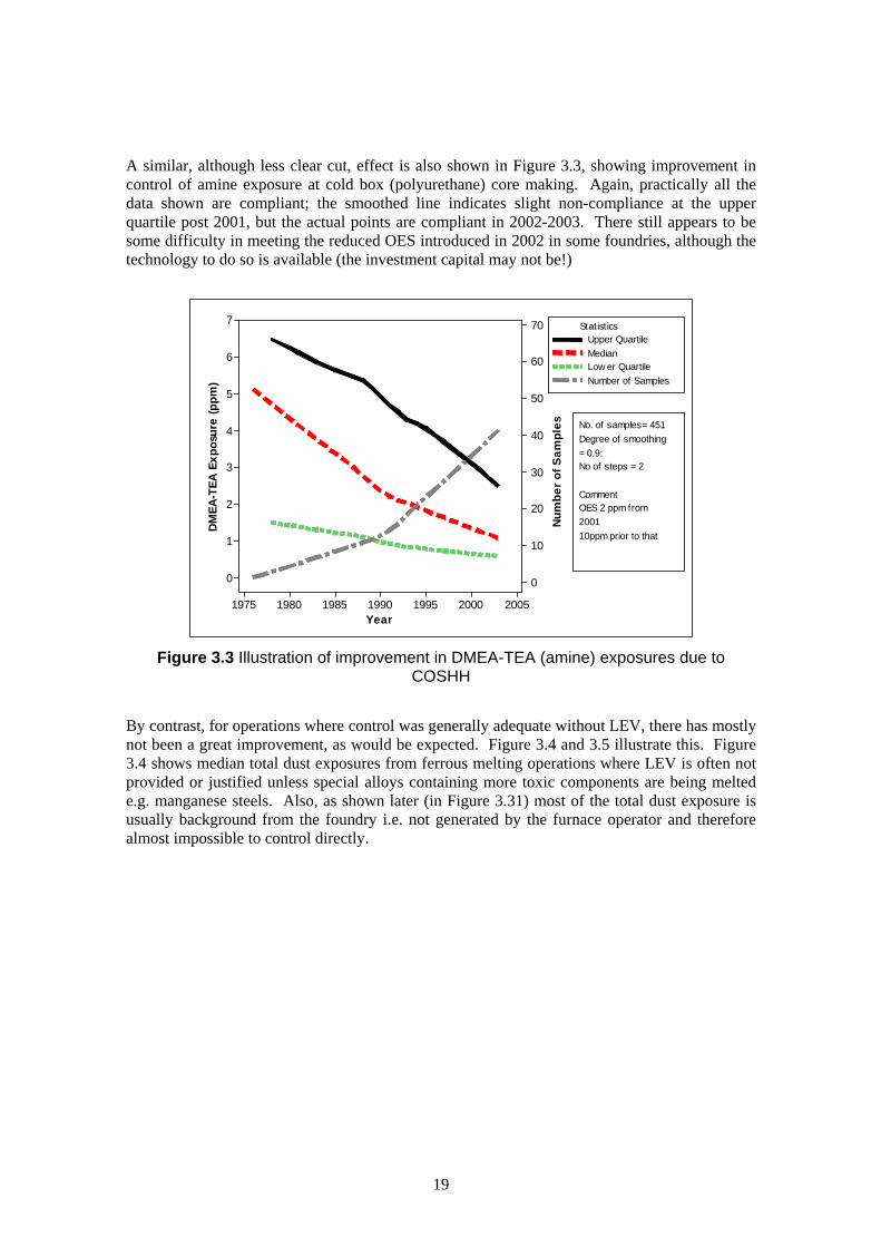
A similar, although less clear cut, effect is also shown in Figure 3.3, showing improvement in control of amine exposure at cold box (polyurethane) core making. Again, practically all the data shown are compliant; the smoothed line indicates slight non-compliance at the upper quartile post 2001, but the actual points are compliant in 2002-2003. There still appears to be some difficulty in meeting the reduced OES introduced in 2002 in some foundries, although the technology to do so is available (the investment capital may not be!)
Year
DM
EA-T
EA E
xpos
ure
(ppm
)
Num
ber o
f Sam
ples
2005200019951990198519801975
7
6
5
4
3
2
1
0
70
60
50
40
30
20
10
0
VariableUpper QuartileMedianLow er QuartileNumber of Samples
Statistics
No. of samples= 451Degree of smoothing= 0.9;No of steps = 2
CommentOES 2 ppm from200110ppm prior to that
Figure 3.3 Illustration of improvement in DMEA-TEA (amine) exposures due to
COSHH
By contrast, for operations where control was generally adequate without LEV, there has mostly not been a great improvement, as would be expected. Figure 3.4 and 3.5 illustrate this. Figure 3.4 shows median total dust exposures from ferrous melting operations where LEV is often not provided or justified unless special alloys containing more toxic components are being melted e.g. manganese steels. Also, as shown later (in Figure 3.31) most of the total dust exposure is usually background from the foundry i.e. not generated by the furnace operator and therefore almost impossible to control directly.
19

Med
ian
Tota
l Dus
t Exp
osur
e (m
gm-3
)
20052000199519901985198019751970
14
12
10
8
6
4
2
0
No of samples= 83Degree ofsmoothing = 1No of steps = 2
Figure 3.4: Trends in total dust exposure at melting
Figure 3.5 shows median carbon monoxide exposures from all operations, again not normally controlled at the operator’s position.
Med
ian
Carb
on M
onox
ide
Expo
sure
(ppm
)
2005200019951990
50
40
30
20
10
0
No of samples = 2371
Figure 3.5 Trends in carbon monoxide exposure
20

Working conditions almost certainly started to improve prior to COSHH but these Regulations did provide some leverage to persuade foundries to make further improvements. As shown above in Figure 3.1, there was an upsurge in the number of surveys carried out in 1989 and 1990, immediately following the introduction of COSHH. When carrying out these surveys it was found that most foundries already had LEV, to the then recommended specification, in place where dust control was required and believed that they would therefore comply easily with the COSHH exposure limits. Unfortunately most of the LEV was poorly designed and/or not used properly and many exposures were found to be non-compliant. Foundries which had recently installed new LEV systems such as fettling benches and booths were naturally reluctant to dispose of them and replace them with better designed ones. In many cases several years of high exposures elapsed before improvement to LEV was undertaken. In the meantime most fettling shops became mandatory RPE zones and this provided even less incentive to improve LEV. It also allowed the development of habitual poor working practice such as working between work piece and LEV. Case studies one and two illustrate these points.
CASE STUDY 1 Foundry 1 (hdp 485) is a small iron foundry using chemically bonded sand, electric
melting and mostly floor moulding/ casting. In 1997/1998 a complete renovation of
the foundry was undertaken, including the provision of new fettling facilities and a
moulding/casting pit.
Looking at the respirable silica results from the two fettlers in Figure 3.6,
particularly the higher results from heavy fettling, with time an interesting story
emerges. Prior to the renovation a large downdraft fettling bench was used. It was
well maintained to design specification and used as well as practicable but quite
inappropriate to the sort of fettling being carried out and therefore led to
unacceptable exposures and compulsory RPE.
The provision of a new rear draft heavy fettling booth with a turntable coincided
with a different heavy fettler and for the first two years it proved difficult to
persuade him not to work between the casting and the back of the booth.
The lower of the two highest exposures in 2000 was a retest when the fettler was
constantly supervised to ensure proper use of booth and turntable, resulting in a
just about acceptable exposure. Since then exposure has consistently been below
the recommended level of 0.1 mg/m3, showing the difference between poorly
designed LEV and well designed LEV for a difficult fettling task with much adhering
sand. It also shows that good design is not sufficient; the LEV must be used
properly as well. In fact the latter appears more important in terms of exposure.
21

Res
pira
ble
Silic
a Ex
posu
re (m
gm-3
)
200420022000199819961994
1.1
1.0
0.9
0.8
0.7
0.6
0.5
0.4
0.3
0.2
0.1
0.0
Figure 3.6: Respirable silica exposures from fettling for case study 1
CASE STUDY 2 Foundry 2 (hdp 686) is a small jobbing steel foundry using chemically bonded
sand and cores and electric melting, making small to medium castings. It has a
culture of reliance on RPE for control, with poor maintenance and use of LEV in
spite of continual prompting from the hygienist carrying out the monitoring. For
one year (1999), after obtaining some very poor results, the hygienist succeeded
in persuading the foundry to renovate the fettling booths (low profile) to design
specification and the fettlers to keep their fettling stands close to the booths, with a
corresponding dramatic reduction in fettling exposure. Unfortunately there was a
rapid return to bad habits (see Figure 3.7).
Comment: The line at 0.1 mg/m3 represents the action level/ recommended exposure limit
22

Res
pira
ble
dust
exp
osur
es (m
gm-3
)
2002200019981996199419921990
20
15
10
5
0
NoteRespirable dust exposure limit,Prior to 1997 = 5Post 1997 = 4
Figure 3.7: Respirable dust exposures from disc grinding at foundry 2
This again illustrates the need for proper design of fettling facilities for current
applications, maintenance to those design specifications and proper use in order
to give adequate control. 3.1.2 Effects of Other Legislative Changes Other legislative changes such as the introduction of new MEL’s might have been expected to have led to improvements in control of specific analytes. 3.1.2.1 Silica MEL (1992)
For many years the foundry industry had used the Recommended Limit (later OES) of 0.1 mg/m3 as a base standard for respirable silica exposure. With the intention of tightening control, in 1992 HSE introduced an MEL for silica to bring in the additional compliance requirement to reduce exposures as far as reasonably practicable below the limit. The MEL was initially set at 0.4 mg/m3, mainly to accommodate the quarry industry, which at that time were unable to achieve a lower limit. However, for other industries with significant silica exposure, including the foundry sector, sector guidance was provided recommending that it was considered reasonably practical for these sectors to achieve the previous lower level of 0.1 mg/m3 and that the lower level should be used as an action level. Later in 1996/7, the MEL was reviewed, and, as a result of the changes in respirable dust convention, which occurred at the same time (see later), reduced to 0.3 mg/m3. However, at this stage, the earlier sector guidance was withdrawn and not replaced, and in the documents advising of the modified MEL no mention was made of some sectors being able to work to lower levels. From this time many monitoring agencies were apparently comparing levels with the MEL rather than a lower action level, with a consequent relaxation of control enforcement (newer
23

hygienists were probably not aware of the history of the MEL) leading to a slight drift upwards in exposure levels. (The author had private view of a number of reports in the course of auditing activities etc including some where no action was recommended for exposures to silica of 0.14 mg/m3, “because the results were substantially [< half] below the MEL”). At Alvechurch the action level of 0.1 (0.08 post convention change) was always applied. UKAS prevented Sheffield from using unofficial limits, although the senior monitoring consultant was well aware of the history and generally gave appropriate advice. Cti’s data suggest no obvious changes as the result of the introduction of the silica MEL in 1992 and no more than a hint of a temporary drift upwards in the late 1990’s.
3.1.2.2 Ferrous Foundry Particulate MELs (1996/7)
Following a suggestion that there was possibly a slight excess of cancer among some foundry workers, HSE sponsored research projects were set up to explore this with a view to identifying the agent(s) concerned, if any, and recommending appropriate action (Isherwood 1986, Levy et al. 1994). No specific agents were found, although considerable attention was focussed on organic materials, but the project concluded that in the absence of any specific substances, particulates should be used as a measure of exposure. As a result, Ferrous Foundry Particulate (FFP) MELs were introduced in 1996/7 at 10 mg/m3 (inhalable dust) and 4 mg/m3 respirable dust (the same numerical values as the previous nuisance dust OESs). Cti (then known as CDC) felt that the research was seriously flawed, and a submitted response to this effect was apparently not taken into account in setting the new limits. The new limits may well, therefore, not have been pressed as hard as they might have been, although our Members were made well aware of them. All results were clearly compared with the FFP MELs and appropriate advice given. Nevertheless, the data show no clear evidence of a change as a result of their introduction.
3.1.2.3 Change in Respirable Dust Convention (1996/7)
Prior to 1996 there were two respirable dust conventions (definitions of capture efficiencies of various size fractions) in use internationally, which differed significantly. These were the Johannesburg Convention (used in UK, commonwealth countries and much of Europe) and the American ACGIH (American Conference of Governmental Industrial Hygienists) Convention (used in USA and much of Asia). A single compromise convention, the CEN (Comite Europeen de Normalisation) convention was proposed and accepted in 1996 to replace both the earlier conventions. The result of this decision in the UK was that cyclones would have to be used at a higher sampling rate, which causes a greater proportion of the sampled dust to be rejected as non-respirable. Hence a step reduction in respirable dust and respirable silica exposures would be expected at the adoption of the new convention and sampling conditions. The Cti data quite clearly show the expected step change in respirable dust due to the convention change in 1996/7 although the immediate reduction was not always maintained (see comments in Section 3.1.2.1). Respirable dust and respirable silica are not independent analytes; silica is a component of the respirable dust. The two fractions are therefore inevitably controlled together, and silica is usually the more critical analyte (Figure 3.8).
24

Med
ian
Res
pira
ble
Dus
t Ex
posu
re (
mgm
-3)
20042002200019981996199419921990
1.4
1.2
1.0
0.8
0.6
0.4
0.2
ByVar3
S Post 97S Pre 97
Pre postA Post 97A Pre 97
No. of samplesAlvechurch Post 97 Data - 334Alvechurch Pre 97 Data - 382Sheffield Post 97 Data - 4566Sheffield Pre 97 Data - 2504
Comment: NB The step change of ~30% expected over the introduction of the new convention in 1997 is superimposed on general downward trends in exposures
which may be somewhat different for the two sites (see also Figure 3.18).
Figure 3.8: Effect of respirable dust convention change
3.1.2.4 Environmental Protection Act (1990) There are interesting changes to magnesium fume exposures with time. Magnesium is added to cast irons as metal or alloy in a separate process to modify the nature of the graphite content of the cast iron to spheroidal graphite (SG) to make the iron stronger but less brittle – more steel-like. Exposures from this process showed a steady increase up to about 1996 although still generally satisfactory, concurrent with a major increase in the production of SG iron, which continues, but with a dramatic fall-off since. The latter effect is almost certainly due to the increased use of fume-suppressant techniques for magnesium treatment to prevent fugitive emissions prescribed in the Process Guidance Notes under the Environmental Protection Act (1990) from the 1996 revision.
25

Med
ian
Mag
nesi
um E
xpos
ure
(mgm
-3)
2004200220001998199619941992
0.8
0.7
0.6
0.5
0.4
0.3
0.2
CommentVery lowmagnesiumexposures fromordinary furnacefume removed.
LOWESS Smoother: degree of smoothing = 0.6; number of steps = 2. No. of samples = 109
Figure 3.9: Variation in magnesium exposure from SG treatment with time
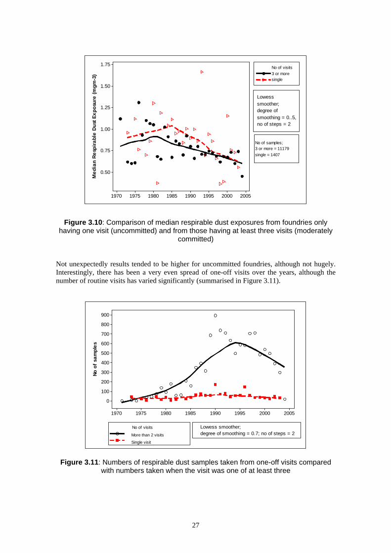
3.2 RELATIONSHIPS BETWEEN VARIOUS DATA SUBSETS AND THE INFLUENCES ON EXPOSURE Superimposed on the general trends initiated by COSHH, differences between various sub-sets of data were found. These additional influences are explained in the following sections. 3.2.1 Effect of Commitment In an attempt to assess the possible effect of the degree of commitment to health and safety by the foundry on personal exposures, comparisons were made between Respirable Dust (RD) results obtained from foundries for which we had only made one visit and those for which we had data from 3 or more visits. These represent foundries that are uncommitted vs fairly committed to improvement; the results are shown in Figure 3.10.
26
Med
ian
Resp
irabl
e D
ust E
xpos
ure
(mgm
-3)
20052000199519901985198019751970
1.75
1.50
1.25
1.00
0.75
0.50
No. of visitsGreater than 3
Less than 2
No of visits3 or moresingle
Lowesssmoother;degree ofsmoothing = 0..5,no of steps = 2
No of samples;3 or more = 11179single = 1407
Figure 3.10: Comparison of median respirable dust exposures from foundries only having one visit (uncommitted) and from those having at least three visits (moderately
committed) Not unexpectedly results tended to be higher for uncommitted foundries, although not hugely. Interestingly, there has been a very even spread of one-off visits over the years, although the number of routine visits has varied significantly (summarised in Figure 3.11).
No o
f sa
mpl
es
20052000199519901985198019751970
900
800
700
600
500
400
300
200
100
0
No. of visitsGreater than 3
Less than 2More than 2 visits
Single visit
Lowess smoother;degree of smoothing = 0.7; no of steps = 2
No of visits
Figure 3.11: Numbers of respirable dust samples taken from one-off visits compared with numbers taken when the visit was one of at least three
27

3.2.2 Effect of Foundry Type (Steel or Iron) and Size on Exposure Respirable dust exposure was used as a reliable indicator of controls because it responds well to effective LEV, the two different cyclones have been validated as giving equivalent results for RD. In addition, only gravimetric analysis is required and practically all results will be above the detection limits. Median respirable dust exposures were plotted against time for the various size groups (small, small medium, large medium, large) for each of the two major foundry types (steel and iron). Although not absolutely conclusive, the initial indications are interesting and warrant further investigation. There appeared to be little difference between iron and steel foundries overall (Figure 3.12), especially in the period 1985 to 2000 when there is most data, although post 1990 steel results appear somewhat higher than those from iron foundries.
Med
ian
Resp
irabl
e Du
st E
xpos
ure
(mgm
-3)
20052000199519901985198019751970
1.50
1.25
1.00
0.75
0.50
ByVar2Casting of iron
Casting of steelCasting of Iron - 5455Casting of Steel - 5909
No of samples LOWESS Smoother;degree of smoothing = 0.5;no of steps = 2
Figure 3.12: Comparison of respirable dust exposures between iron and steel foundries
For both foundry types (see Figures 3.13 and 3.14) the two medium size groups (50 – 150, 150 – 250) did not appear significantly different, were generally of lower exposure than the other groups and showed little change with time. By contrast both large and small size groups tend to have higher exposure levels especially in the early years and a tendency to lower exposures latterly from visual inspection of graphs. Since about 2000 there appears no obvious difference with size. Particularly for iron foundries, there may be an indication that the decrease in exposure started later for small foundries than for the large foundries (~ 1995 cf ~ 1990), which might be expected (see Figure 3.13). However there may be some confounding factors:
• Particularly for steel there are relatively few data for large foundries.
• Foundries have been closing in increasing numbers since the mid 1990’s and many have been either in the small or the large category, and it is at least possible that in these size groups only the best ones have survived (this would require further investigation outside the remit of this project).
28

• Much of the data is from the medium size groups and so there is less variation in the medians because of larger sample sizes. There are, however, indications that some foundries in these classes have improved markedly while others have got worse. More detailed study of the data distributions would be required to clarify the situation.
M
edia
n R
espi
rabl
e D
ust E
xpos
ure
(mgm
-3)
2005200019951990198519801975
1.4
1.2
1.0
0.8
0.6
0.4
0.2
size iron
C Small mediumD Small
A LargeB Large medium
No. of samplesLarge - 2316Large medium - 1027Small medium - 1585Small - 527
LOWESS Smoother;Degree of smoothing= 0.5, No. of steps =2
LargeLarge mediumSmall mediumSmall
Figure 3.13: Variation of respirable dust exposure in iron foundries with size
Med
ian
Resp
irabl
e Du
st E
xpos
ure
(mgm
-3)
20052000199519901985
2.5
2.0
1.5
1.0
0.5
size steel
C Small mediumD Small
A LargeB Large medium
No. of samplesLarge - 216Large medium - 1258Small medium - 3216Small - 1219
LargeLarge mediumSmall mediumSmall
LOWESS Smoothing:Degree of smoothing= 1; no of steps = 2
Figure 3.14: Variation of respirable dust exposure in steel foundries with size
29

CASE STUDY 3 Foundry 1 (hdp 485) is a small iron foundry using chemically bonded sand, electric
melting and mostly floor moulding/casting. In 1997/1998 a complete renovation of
the foundry was undertaken, including the provision of new fettling facilities and a
moulding/casting pit. The effect on fettling was discussed in Case Study 1.
A second effect of the renovation is less clear cut but there are some indications of
a reduction in respirable silica exposure for the non-fettling operations (manual
knockout, reclaim) before and after conversion from a complete sand floor foundry
to a foundry where sand was largely confined to the moulding/casting pit and the
knockout area. It should be noted that attempts were being made to keep
walkways clear of sand even before the renovation (see Figure 3.15). Case Study
4 (see later) also shows the effects of a sand floor on exposure.
Resp
irabl
e Si
lica
Expo
sure
(mgm
-3)
200520042003200220012000199919981997199619951994
0.18
0.16
0.14
0.12
0.10
0.08
0.06
0.04
0.02
0.00
Action level at 0.1mgm-3
Figure 3.15: Comparison of respirable silica results from knockout/reclaim operations before and after changing from a sand floor foundry to largely concrete floor foundry
3.2.3 Mutual Validation of NEDB/Cti Foundry Data As part of the validation of the data set, comparisons were made between the two Cti sets and the NEDB foundry set. It was possible, using the link column, to examine the triads (total inhalable dust, respirable dust and respirable silica) from each sample, which had not previously been possible within the NEDB. Comparison of the three whole databases indicated that for
30

respirable dust, the most reliable of the three analytes, the three sets of data appeared to come from similar populations based on very considerable overlap (see Figure 3.16). The higher scatter from the NEDB data probably arises from the smaller sample numbers and much smaller number of visits, where extreme values have relatively higher influence. The same comparison carried out using only data from the foundries used for case studies, giving a much smaller variation in sample size between the three sets of data, showed a similar result. This is displayed in Figure 3.17
Med
ian
Res
pira
ble
Dus
t Ex
posu
re (
mgm
-3)
20052000199519901985198019751970
1.8
1.6
1.4
1.2
1.0
0.8
0.6
0.4
0.2
0.0
DatasetCTIACTISNEDB
Alvechurch - 1911Sheffield - 6511NEDB - 267
No of samples
Figure 3.16: Comparison of respirable dust exposures from three data sets
Med
ian
Resp
irabl
e Du
st E
xpos
ure
(mgm
-3)
20052000199519901985
2.0
1.5
1.0
0.5
0.0
DatasetCTI ACTI SNEDB
Comment:Case studyfoundries only
No of samplesAlvechurch 367Sheffield 1941NEDB 267
Figure 3.17: Comparison of respirable dust exposures from NEDB with Cti from case study foundries
31

3.2.4 Comparisons of Alvechurch and Sheffield Data It was fortuitous, although very useful for this project, that the two Cti sites offer somewhat different types of monitoring service with that from Sheffield being perhaps more typical of the major monitoring agencies, whilst that from Alvechurch is perhaps more typical of that of a lone qualified hygienist doing his or her own monitoring and giving specific advice based on the results and observations. Again, using respirable dust as a robust analyte, comparison of the two data sets with time appears to show a different pattern of exposure change although there is improvement from both sites (see Figure 3.18). The differences are shown over the bulk of the exposure distribution so appear to be real, although actual level differences between the sites are small.
Res
pira
ble
Dus
t Ex
posu
re (
mgm
-3)
20052000199519901985
2.0
1.5
1.0
0.5
0.0
Variable
C32 * C29C33 * C29
Lower Quartile * Year xMedian * Year xUpper Quartile * Year xC31 * C29
Lower Quartile - AlvechurchMedian - AlvechurchUpper Quartile - AlvechurchLower Quartile - SheffieldMedian - SheffieldUpper Quartile - Sheffield
CommentAll data from iron and steelfoundries plus steel forging.
LOWESS smoother:degree of smoothing = 0.5;no. of steps = 2.
No. of samplesSheffield - 2879Alvechurch - 1638
Figure 3.18: Comparison of respirable dust exposure distributions from the
two Cti sites The results from Alvechurch indicate a fairly steady improvement throughout with perhaps a faster rate of improvement post COSHH. The Sheffield results show less change in exposure (ignoring RPE) after an initial decrease, although the hygienist felt there had been some improvement. However, some of the improvement may have been more people wearing better RPE which, of course, will not change measured exposures. Also it may well be that some sites have improved while others have got worse. This is an aspect worthy of further investigation. Carrying out the same comparison using data just from the Case Study foundries, a difference in history was confirmed (Figure 3.19).
32

Resp
irabl
e Du
st E
xpos
ure
(mgm
-3)
2005200019951990198519801975
3.5
3.0
2.5
2.0
1.5
1.0
0.5
0.0
Variable
Median2 * R D AQ3_2 * R D A
Q1_1 * R D SMedian1 * R D SQ3_1 * R D SQ1_2 * R D A
Lower Quartile - SheffieldMedian - SheffieldUpper Quartile - SheffieldLower Quartile - AlvechurchMedian - AlvechurchUpper Quartile - Alvechurch
No of samplesSheffield - 1943Alvechurch - 367
LOWESS Smoother: degree of smoothing = 0.5;No. of steps = 2.
Figure 3.19: Comparison of respirable dust exposure distributions from the two Cti sites, case study foundries only
The Alvechurch approach was to focus attention on one or two of the problem areas and provide detailed advice on how to address them, and then move on to other areas in subsequent surveys thus encouraging continual improvement towards a situation where RPE is not actually needed. An approach which advises on all problem areas at once may be more daunting. This may account for the generally smoother improvement although with a smaller data set. The reasons for the inter site differences are as yet unclear but may involve at least the nature of the consultancy (routine vs tailor-made survey/advice), the clientele (clients prepared to pay a premium for a bespoke service may be more likely to follow recommendations while clients attracted to a cheaper service may not wish to spend money on engineering improvements) and, possibly, in some cases the personalities involved both in the client companies and monitoring teams. For instance, clear advice may be given verbally to the site contact, but written less forcibly in the official report. The advice may not be passed on strongly to managers, maintenance staff etc who should take action. An interesting point is that over the last few years respirable dust exposure distributions in the data sets from the two sites seem virtually identical in spite of different histories. This aspect should probably be explored further to determine the influences behind the differences, e.g. differences in sand systems etc. Also further analysis of the data may perhaps lead to some pointers as to what aspects of monitoring/consultancy are necessary for effective encouragement to improve. 3.3 USE OF DATA TO INFORM Examination of exposure data for various analytes can be used to inform enforcement agencies (whether official or unofficial) in two major ways. Trends, particularly adverse trends, can point towards specific control strategies, and exposure levels and their distributions can inform the limit setting process as to achievability. In many cases the data can be used in both ways.
33

This makes it difficult to segregate analytes on the grounds of application. Various critical analytes are considered separately, starting with some of particular current interest. 3.3.1 Silica Exposure Statistics For the first time it was possible, as a result of this project, to provide reliable objective estimates of proportions of exposures above various potential exposure limits to inform the preparation of the Regulatory Impact Assessment for the proposed Respirable Crystalline Silica Workplace Exposure Limit (WEL). Post 1998, when exposure levels were not changing rapidly, our data obtained at the time of consultation (2245 points) showed that 2% of exposures were above 0.3 mg/m3, 10% were above 0.1 mg/m3, 25% were above 0.05 mg/m3 and 75% of exposures were above 0.01 mg/m3, the suggested possible values for the new limit. From the full database, post 1998 there were 4747 data points from 167 foundries, showing that overall, 5% of exposures were above 0.3 mg/m3, 18% were above 0.1 mg/m3, 40% were above 0.05 mg/m3 and 86% were above 0.01 mg/m3, although the last may be an over-estimate as some “less than” results will be included. The differences, although not great, perhaps illustrate the variability between foundries within the data set. Most of the highest exposures were from intermittent operations such as furnace wrecking or from difficult fettling operations on unshotblasted castings. 3.3.2 Formaldehyde Exposures As can be seen from Figures 3.20 and 3.21, there was a very large early reduction in exposure levels with relatively little change from about 1990, when best reasonably practicable control had largely been achieved. The early improvement in control was largely through the provision of extraction on core/moulding machines, especially for processes giving high formaldehyde such as hot box, and development of resins with low free formaldehyde. There has also been a contribution from the replacement of the hot box core system, largely by cold box polyurethane.
Form
alde
hyde
Exp
osur
e (p
pm)
200520001995199019851980
3.0
2.5
2.0
1.5
1.0
0.5
0.0
Variable
Upper Quartile
Low er QuartileMedian
No ofsamples =1354
Degree ofsmoothing = 0.5,No. of steps = 2
Comment Includes datafrom diffusiveindicator tubes
Figure 3.20: Trends in formaldehyde exposure – all data
34

Year
Med
ian
Form
alde
hyde
Exp
osur
e (m
gm-3
)
200520001995199019851980
5
4
3
2
1
0
No. of samples = 149, LOWESS Smoother, degree of smoothing = 0.55, no of steps = 2
Figure 3.21: Median exposure to formaldehyde – hot box
In view of the recent IARC (International Agency for Research on Cancer) re-evaluation of the carcinogenicity status of formaldehyde, the current MEL is also due for review shortly. To support this review, exposure statistics for the main formaldehyde containing binder systems are presented in Table 3.1. These results are mainly based on Alvechurch data but the cold box results are post 1999 Sheffield, as there were very little Alvechurch data.
Sand System Median (mg/m3) Upper Quartile
(mg/m3) No of Data Points
Alkaline phenolic 0.12 0.3 23
Furane 0.24 0.5 60
Cold box 0.09 0.23 20
Shell 0.22 0.43 71
Hot box 0.9 1.9 54
Table 3.1: Formaldehyde exposure levels for different sand systems
Without this project, such data would not have been readily available. 3.3.3 Furfuryl Alcohol Exposures Furfuryl alcohol is a major component from furane sand systems (and to a lesser extent hot box). The furane system is probably the most popular chemically bonded system for smaller jobbing iron foundries due to its technical properties. It also has environmental advantages in that furfuryl alcohol is produced from a sustainable source. Recent interest has been initiated by the publication of an American study which suggests the possibility of carcinogenic effects. The interpretation of this is still under discussion.
35

Some years ago it was shown that it was possible to maintain good binder characteristics while reducing formaldehyde levels, by increasing the furfuryl alcohol content of kettled resins, although the resulting resins were much more expensive. Recently some resin suppliers have introduced much cheaper blended high furfuryl alcohol resins, which also have low free formaldehyde contents and purport to be as good as the kettled resins. However, a number of technical problems have shown up and exposure levels for furfuryl alcohol appear to have greatly increased (see Figure 3.22). Cti is intending to collate its data and issue a briefing note which will inform Members of the drawbacks to this economically favourable development. The median is generally less than ~2 ppm; upper quartile generally less than ~8 ppm (compared with previous OES of 5 ppm).
Furf
uryl
Alc
ohol
Exp
osur
e (p
pm)
Num
ber o
f sam
ples
200520001995199019851980
10
8
6
4
2
0
35
30
25
20
15
10
5
0
Variable
Upper QuartileNumber of Samples
Lower QuartileMedian
CommentApparent increase inexposure latterly. May bedue to more intensive useof cheaper blended highfurfuryl alcohol resinsespecially in smallerjobbing foundries.
LOWESS Smoother:Degree of smoothing = 0.5;no of steps = 2.
Figure 3.22: Variation of exposures to furfuryl alcohol with time – all data 3.3.4 Manganese There is little change in exposure level with time, but there remains a small percentage of exposures above the current MEL of 0.5 mg/m3 from working with manganese steel (as predicted in Cti’s response to the HSE consultation carried out in 2000/1 (HSE, 2000). Manganese is added to steel to improve impact resistance. The median is generally less than 0.08 mg/m3; upper quartile generally less than 0.2 mg/m3. 3.3.5 Nickel There seems to be a trend to higher exposures especially in the upper quartile since about 1999 possibly reflecting an increased use of high nickel irons and steels (this could be worrying for foundries if the trend continues) – Figure 3.23). An alternative explanation could be that more samples are now being taken on fettling operations on high nickel alloys, which may be a problem only recently recognised. Nickel is used to increase hardness and wear resistance. The median is generally less than 0.1 mg/m3; the upper quartile was below 0.3 mg/m3 but now seems to be around the MEL of 0.5 mg/m3.
36

Nick
el E
xpos
ure
(mgm
-3)
Num
ber o
f Sam
ples
200520001995199019851980
0.5
0.4
0.3
0.2
0.1
0.0
50
40
30
20
10
0
Variable
Upper QuartileNumber of Samples
Lower QuartileMedian
LOWESS Smoother:degree of smoothing = 0.5:no. of steps = 2.
Comment: Upper quartileoff scale at: 0.64 for2002; 0.53 for 2003.Scale restricted to showstructure to lowerpercentiles.
Figure 3.23: Nickel exposures
Figure 3.24 shows the distribution of source groups for the nickel exposure data. Interestingly, no detectable nickel has been found at melting.
0
5
10
15
20
25
No
of s
amp
les
Thermal Cutt ing Dress ing
Figure 3.24: Distribution of source groups for nickel exposure data
3.4 RELATIONSHIPS BETWEEN DIFFERENT DATA SUBSETS FOR INFORMATION There are a number of situations where one analyte or sample category is a component or subset of another. In the hypotheses it was thought to be useful to explore the relationships between these pairs of subsets to:
37

• Determine if one could usefully be predicted from the other • Determine likely ranges of one in relation with the other in order to provide a check that
results were sensible or not. Results outside the likely range should probably be questioned (test repeated, explanations sought), or
• Monitor how processes/operations/industries are changing by consideration of the relationship between these subsets.
Some of these situations are considered in this section. 3.4.1 Relationships between respirable silica and respirable dust As suggested in the hypotheses, the association between respirable dust and respirable silica for various groups of foundry jobs was examined with a view to assessing the possibility of being able to predict silica exposure from respirable dust exposures, or at least establishing a likely range of silica contents in the respirable dust. A simple regression analysis did not give any useful information although it is understood that Dr Thompson has explored this approach further. As an alternative approach, histograms of percentage silica in the respirable dust were determined for the main dust producing job groups. Percentage silica was calculated from each pair of linked silica and respirable dust data after removing all pairs where the silica data were “less thans” and hence undefined (although a number had been allocated to them). Basic statistics (lower quartile, median, upper quartile and number of data pairs) were obtained from the data base and an estimate of the likely upper percentage limit was made from observation of the histograms for each job group. Some histograms gave an indication of possible bimodality and the positions of the possible minor second peaks were also estimated visually. This data is summarised in Table 3.2.
Job Group Lower Quartile
Median Upper Quartile
Possible Second
Minor Peak
Upper Limit
Number of Data Points
All data 3.6 6.3 10.5 ~20 ~35 6040 Cut-off/knockoff 4.6 8.4 15.3 ~18 ~40 244 Shotblast 5.6 9.4 13.7 ~22 ~35 401 Fettling 3.7 6.4 10.0 ~25 ~30 1378 Thermal cutting 1.2 1.9 3.4 ~15 ~20 153 Core making 3.8 6.7 12.1 ~38 ~40 260 Moulding 3.4 5.4 9.1 ~20 ~35 814 Reclaim 4.0 6.4 9.3 ~30 84 Knockout 4.2 6.7 10.3 ~20 ~35 483 Wrecking overall 5.3 9.8 22.0 148 Ladle fettling 4 6 10 ~35 81 Cupola fettling 7 12 20 ~45 39 Furnace wrecking 41 59 72 ~90 28
Table 3.2: Silica contents (%) of respirable dust for various job groups
One distribution stood out as very different from the others, from wrecking operations, and this group was further split into its three component operations (see Figure 3.25). It was apparent that electric furnace wrecking had a very different distribution from the other two, which were similar with much overlap, but possibly not identical. Cupola fettling and ladle dressing
38

generally use similar lining materials (ganister) and similar techniques for removal of old lining and patching in new material so it is not surprising that the dust compositions are similar. By contrast, electric furnace linings are often removed by push-out and new water-free lining material is vibrated in and then fritted. Many linings contain silicates, including fibrous silicates, and such materials gradually break down under prolonged heating above 1000°C to form cristobalite, a form of silica, accounting for the high silica content of the dust produced.
0
5
10
15
20
25
0 10 20 30 40 50 60 70 80 90
Percentage Silica in Respirable Dust
Freq
uenc
y
Ladle DressingFurnace WreckingCupola Fettle
Figure 3.25: Distributions of silica contents of respirable dust for
wrecking operations
The remaining jobs fall generally into three sets. The dust from thermal cutting operations seems to have a very low silica content (generally less than 5%) in spite of often being carried out prior to shotblasting (see Figure 3.26). The remainder of the dust is presumably some combination of metal fume and soot and fume from fluxes etc.
Percentage silica in respirable dust
Freq
uenc
y
1009080706050403020100
90
80
70
60
50
40
30
20
10
0
Lower Quartile - 1.2: Median - 1.9: Upper Quartile - 3.4: No. of samples - 153 Figure 3.26: Distribution of silica content of respirable dust at thermal cutting
39

Cut-off/knockoff operations (normally carried out prior to shotblast) and shotblasting itself have the highest silica contents of normal continuous operations (median ~8% – 9%, significant samples up to about 30% silica). Particularly in the case of shotblast, respirable dust in these operations is generated by fracture of sand particles (see Figure 3.27).
Percentage silica in respirable dust
Freq
uenc
y
1009080706050403020100
70
60
50
40
30
20
10
0
Median - 5.6: Lower Quartile -9.4: Upper Quartile -13.7: No of samples - 401 Figure 3.27: Distribution of silica contents in respirable dust at shotblast
The remaining job groups, fettling, core and mould making and knockout/reclaim seem to have similar silica content distributions (median ~6% with practically all samples below 30% silica) although the composition of the remainder of the respirable dust will vary considerably, with relatively high metallic content in fettling dusts, but clay, coal dust and/or resin residues being present in the moulding/knockout operations. Figures 3.28 for fettling and 3.29 for knockout illustrate these.
Percentage silica in respirable silica
Freq
uenc
y
1009080706050403020100
250
200
150
100
50
0
Lower Quartile - 3.7: Median - 6.4: Upper Quartile - 10: No of samples - 1378 Figure 3.28: Distribution of silica contents in respirable dust at fettling
40

Percentage silica in respirable dust
Freq
uenc
y
1009080706050403020100
100
80
60
40
20
0
Lower Quartile - 4.2: Median - 6.7: Upper Quartile - 10.6: No of samples - 483 Figure 3.29: Distribution of silica content of respirable dust from knockout operations
The actual dust levels will also vary with job group, the highest levels being generated in the wrecking operations (although it is sometimes practicable to use LEV control for ladle dressing), the next in thermal cutting, then fettling operations, followed by knockout/reclaim/cut-off/knock-off/shotblast, with lowest levels at moulding/coremaking (see Figure 3.30).
Res
pira
ble
Dus
t Res
ult (
mgm
-3)
Corem
aker
Moulder
Knock out
Shot blast
Cut off k
nock of
f
Rec
laim
Fettling
Ladle D
ressi
ng
Therm
al cutt
ing
Cupola Fettli
ng
Furnace wre
ckingAll
10
8
6
4
2
0
CommentPost 1998 data, except for Furnace Wrecking, Cupola Fettling and Ladle Dressing
Figure 3.30: Boxplot of exposures in the various job groups for respirable dust
The most hazardous job would therefore appear to be electric furnace wrecking with both high respirable dust levels and high silica content, although for foundries which carry out the operation themselves this would be only an occasional relatively short term exposure. However, most foundries now use a contractor to do this work and employees of such
41
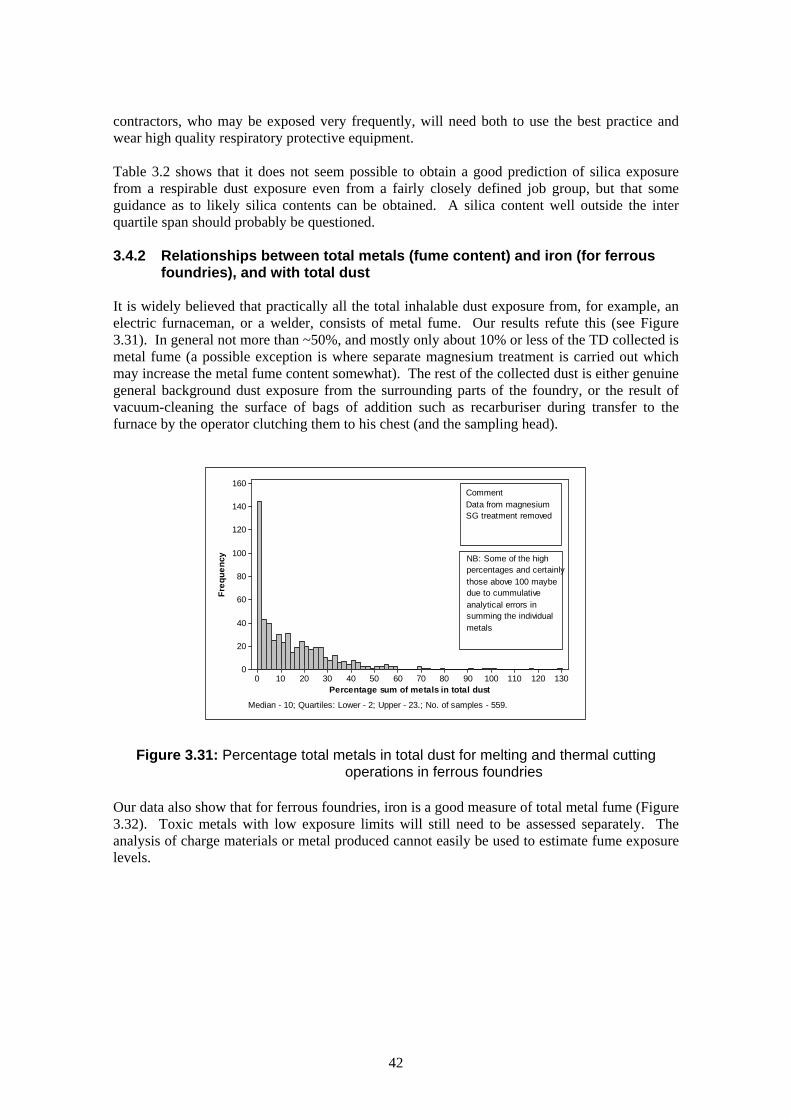
contractors, who may be exposed very frequently, will need both to use the best practice and wear high quality respiratory protective equipment. Table 3.2 shows that it does not seem possible to obtain a good prediction of silica exposure from a respirable dust exposure even from a fairly closely defined job group, but that some guidance as to likely silica contents can be obtained. A silica content well outside the inter quartile span should probably be questioned. 3.4.2 Relationships between total metals (fume content) and iron (for ferrous
foundries), and with total dust It is widely believed that practically all the total inhalable dust exposure from, for example, an electric furnaceman, or a welder, consists of metal fume. Our results refute this (see Figure 3.31). In general not more than ~50%, and mostly only about 10% or less of the TD collected is metal fume (a possible exception is where separate magnesium treatment is carried out which may increase the metal fume content somewhat). The rest of the collected dust is either genuine general background dust exposure from the surrounding parts of the foundry, or the result of vacuum-cleaning the surface of bags of addition such as recarburiser during transfer to the furnace by the operator clutching them to his chest (and the sampling head).
Percentage sum of metals in total dust
Freq
uenc
y
1301201101009080706050403020100
160
140
120
100
80
60
40
20
0
Median - 10; Quartiles: Lower - 2; Upper - 23.; No. of samples - 559.
CommentData from magnesiumSG treatment removed
NB: Some of the highpercentages and certainlythose above 100 maybedue to cummulativeanalytical errors insumming the individualmetals
Figure 3.31: Percentage total metals in total dust for melting and thermal cutting operations in ferrous foundries
Our data also show that for ferrous foundries, iron is a good measure of total metal fume (Figure 3.32). Toxic metals with low exposure limits will still need to be assessed separately. The analysis of charge materials or metal produced cannot easily be used to estimate fume exposure levels.
42

Sum of Metals Exposure (mgm-3)
Iron
Exp
osur
es (m
gm-3
)
35302520151050
25
20
15
10
5
0
Outliers notincluded in line ofbest fit
NB. The two outliers have very unusual metal distributions. Although not labeled as such oneis believed to be from cutting galvanised steel and the other from a copper based alloy.
Figure 3.32: Relationship between total metals and iron for thermal cutting
operations (ferrous foundries)
43

CASE STUDY 4 Foundry 3 (hdp 55) is a large-medium iron foundry which started off as a jobbing
foundry making medium sized engineering castings but with a change of
management decided to go for more intensive production of a restricted range of
smaller castings with much more automation. This foundry generally has a good
attitude to health and safety, but did not foresee all the implications of moving
towards an intensive automated production. In particular, there was an
immediate increase in total dust exposures, which the foundry has had to work
hard to reduce to reasonable levels. The immediate cause was a large increase
in vehicular traffic on the largely sand floor, the main controls being improved
knockout control and regular floor sweeping to prevent sand build-up on traffic
routes.
Tota
l Dus
t Exp
osur
e (m
gm-3
)
Num
ber o
f Sam
ples
20052000199519901985198019751970
16
14
12
10
8
6
4
2
0
20
15
10
5
Variable
Upper QuartileNumber of Samples
Lower QuartileMedian
Figure 3.33: Total dust exposures for hdp 55 This highlights the need for a thorough and realistic risk assessment before
making major changes to the foundry.
3.4.3 Use of Static Samples to Estimate Personal Exposure Two scenarios were considered:
• using respirable dust as an analyte which is mainly sampled in LEV controlled operations
• carbon monoxide (CO) and total dust (TD) at melting, which are often uncontrolled.
44

Not surprisingly, for respirable dust, static sampling was shown clearly to be a poor predictor of personal exposures, generally underestimating by almost a factor of two (see Figure 3.34). Less predictably, perhaps, for CO, and for TD at melting, there was little or no difference between personal and static results (Figures 3.35 and 3.36).
Med
ian
Resp
irabl
e Du
st E
xpos
ure
(mgm
-3)
20052000199519901985198019751970
1.6
1.4
1.2
1.0
0.8
0.6
0.4
0.2
VariableMedian P * yr PMedian S * yr SPersonalStatic
No of samples109011264
LOWESS Smoother: Degreeof smoothing = 0.5;no of steps = 2
Figure 3.34: Comparison of personal and static estimates of respirable dust exposure
Med
ian
Tota
l Dus
t Exp
osur
e (m
gm-3
)
20052000199519901985198019751970
14
12
10
8
6
4
2
0
ByVar2PLSL
CommentThere are farfewer staticsamples thanpersonal.Samples arefrom meltingoperationsonly.
PersonalStatic
No of samples749
Figure 3.35: Comparison of personal and static estimates of total dust exposures
from melting operations
45

Med
ian
CO E
xpos
ure
(ppm
)
2005200019951990
50
40
30
20
10
0
ByVar3PS
PersonalStatic
No of samples2574205
Figure 3.36: Comparison of personal and static estimates of CO exposure
Thus the accepted teaching that static sampling is not a good estimator of personal exposure may only be true for operations which are LEV controlled or where the operator generates the pollutant by his own actions. Static sampling may give reasonable estimates of personal exposure for operations which are not LEV controlled, i.e. where exposure is mainly due to background contamination. 3.4.4 The relationship between ammonia and amine sampling This last section is rather different to the others in that it is the changes in monitoring activity which can inform on the way the foundry industry is developing. There is a clear decrease in the numbers of ammonia samples taken with time together with a marked increase in samples for DMEA/TEA (Figure 3.37). This demonstrates the increasing replacement of traditional shell and hot box core processes by amine cured cold box processes. It also implies that relatively more effort should be spent on controlling amine in the future, especially in the light of the recent reduction in exposure limit.
46

No. o
f Sam
ples
20042002200019981996199419921990
100
80
60
40
20
0
C3Ammonia
DMEA - TEA
Figure 3.37: Sampling frequency of ammonia and amine as an indicator of process changes
47

48

CHAPTER 4
MATTERS ARISING While investigating the data base in order to produce the outcomes described in Chapter 3, a number of unexpected result distributions became apparent, which needed investigation to enable the data to be handled sensibly. The investigations raised a number of important issues, mainly in the area of quality control. Cti has learnt a great deal from this process and presents the issues here so that the more general occupational hygiene community can also learn from our experience. Where relevant, Cti has taken, or is in the process of taking, appropriate action to ensure that a high quality service will continue to be offered in the future, although some of the issues affect other agencies which may put constraints on Cti’s activities. A number of recommendations are made. 4.1 THE DANGERS OF “BLACK BOX” ANALYSIS It became apparent when entering and analysing the respirable silica data from Sheffield that between 1985 and 1992 virtually no silica was detected, while from late 1992 onward, when a new FTIR machine was introduced, silica exposures immediately became comparable with those from Alvechurch. This is illustrated in Figure 4.1.
Med
ian
Res
pira
ble
Sili
ca E
xpos
ures
(mgm
-3)
20052000199519901985
0.10
0.08
0.06
0.04
0.02
0.00
SiteAS
Site No of samplesAlvechurch 1594Sheffield 8524
Figure 4.1: Comparison of respirable silica exposures from the two Cti sites Further internal investigation found that it was likely that the original potassium bromide (KBr) disc infra red (IR) method had been set up properly by someone who knew about IR and occupational hygiene. Following his departure from the environmental team in 1985, the remaining technicians continued to use the method without appreciating all the calibration requirements. Consequently it is likely that the wavelength drifted leading to much reduced
49

sensitivity. The small amount of Sheffield data from late 1984 and early 1985 tends to support this hypothesis of a deterioration of data quality, rather than an inappropriate method as such (see Figure 4.2). Consequently the Sheffield silica data prior to November 1992 have not been used for any other analysis reported in this document and will not be submitted to NEDB.
Res
pira
ble
Silic
a Ex
posu
re (m
gm-3
)
19881987198619851984
0.0150
0.0125
0.0100
0.0075
0.0050
Variable
Median
Lower QuartileUpper Quartile
CommentSheffield data only - no of samples 1032LOWESS Smoother: degree of smoothing = 0.7;no of steps = 2.
Lower QuartileUpper QuartileMedian
Figure 4.2: Illustration of the deterioration of data quality in respirable silica exposure
This incident highlights some important quality assurance issues: • The principles of the method must be fully understood by personnel running the method.
Operators must have a way of detecting a malfunction and must be able to correct it. • Automatic (and manual) analysers need regular calibration, and spectrographic methods
(which include IR and x-ray diffraction (XRD)) need checks on wavelength as well as intensity/absorption. Reference standards of the specific analyte(s) being measured may be a good way of undertaking this.
• Both the analysts concerned and the hygienists submitting the samples should have some
idea of what results are likely from the samples submitted, so that methodology failures can be quickly recognized. Having searchable databases of one’s previous data is very useful in this respect. We have attempted to provide associations between respirable dust values and respirable silica values after removing pairs containing “less-than” silica data for various types of foundry operation, to provide some guidelines (see Section 3.4.1).
4.2 AN APPROPRIATE SAMPLING METHOD MUST NOT ONLY WORK BUT
HAVE ADEQUATE SENSITIVITY Alvechurch developed and used a personal impinger method for formaldehyde involving the reagent 4-amino-3-hydrazino-5-mercapto-1,2,4-triazole (AHMT) and colorimetry at 550 nm. This was not subject to interference from phenol or furfuryl alcohol, which are often also
50

present in foundries where formaldehyde is expected. This method was used until 2001 when the in-house laboratory was closed. Subsequently samples were collected on 2,4-dinitrophenylhydrazine (2,4-DNP) coated silica gel tubes with high performance liquid chromatography (HPLC) analysis. Sheffield used hydroxylamine phosphate based diffusive indicator tubes until about 1998 when some samples were taken/analysed as at Alvechurch. 2,4-DNP tubes have been used from about 2001. The results from the two sites year on year (figure 4.3) show clearly that the diffusive indicator tubes gave apparent low results with almost certainly many false negatives (the medians were fairly consistently “less thans” until 1998), but that the AHMT and 2,4-DNP methods seemed to agree well.
Med
ian
Form
alde
hyde
Exp
osur
e (p
pm)
200520001995199019851980
2.0
1.5
1.0
0.5
0.0
VariableMedian A * yr AMedian S * yr SAlvechurch - 241Sheffield - 1111
Site No of samples
LOWESS Smoother: Degreeof smoothing = 0.5; No ofsteps = 2.
Figure 4.3: Comparison of formaldehyde exposure data from the two Cti sites
Further investigation of the data after removal of the “non-detected” results confirmed that the apparent low results from the indicator tubes were due to an abnormally high number of non-detects and that the method, when it does detect, gives results reasonably in agreement with the other methods used (Figure 4.4). The problem would therefore seem to be a sensitivity issue. A nominal full shift detection limit of about 0.15 ppm was originally considered acceptable, but not reassessed when Cti became aware of the American Occupational Safety and Health Administration (OSHA) limit of 0.1 ppm (which takes into account likely carcinogenicity). Especially taking into account the new status of formaldehyde as a more probable carcinogen it seems quite clear that the current diffusive indicator tubes based on hydroxylamine phosphate should not now be used even for screening for formaldehyde exposure, as significant exposure levels are likely to go undetected. It is recommended that the tube manufacturers try to find some way of increasing the sensitivity significantly (by at least five times).
51

Med
ian
Form
alde
hyde
Exp
osur
e (m
gm-3
)
200520001995199019851980
3.5
3.0
2.5
2.0
1.5
1.0
0.5
0.0
ByVar3AS
Site No of samplesAlvechurch 226 Sheffield 341
LOWESS Smoother: degreeof smoothing = 0.5; no ofsteps = 2.
Figure 4.4: Comparison of formaldehyde exposures with ‘less thans’ removed
As a secondary point it was noted that as from 1999 the number of formaldehyde samples taken from Sheffield fell dramatically, due to limitations on adding additional pumped samplers to men already carrying an uncomfortable amount of sampling equipment (diffusive tubes require no sampling pump and are relatively wearer-friendly). This is illustrated in Figure 4.5.
Num
ber
of s
ampl
es
200520001995199019851980
180
160
140
120
100
80
60
40
20
0
VariableNo of samples A * yr ANo of samples S * yr SAlvechurchSheffield
LOWESS Smoother:Degree of smoothing =0.5; no of steps = 2.
Site
Figure 4.5: Sampling frequency versus time for the Cti sites formaldehyde
52

There may thus be a price to pay for using a better sampling method. Cti is currently assessing the practicality of running several parallel pumped sampling tubes from the same sampling pump. 4.3 REPORTING A reporting issue has shown up during the analysis of the data sets for respirable silica, although the same issue would arise wherever safe levels or exposure limits approach within about an order of magnitude above the detection limit for the analyte. Most contract laboratories and monitoring agencies will nowadays, quite rightly, in principle, be operating under a recognised quality assurance scheme. This project has highlighted an unexpected, and probably unintended, side effect of this. It is best illustrated by a simulated example, based on experience and using typical numbers. Example:
A contract laboratory analysing filters for respirable silica by XRD has a detection limit of 0.016 + 0.002 mg per filter, but the quality assurance (QA) auditors urge that this should be reported as 0.02 mg per filter, implying an error of + 0.005 mg. There is thus not only a larger error than necessary but it is a systematic error.
When we receive the results the first thing we do is divide the results by the air volume we have used for the filter, say 0.8 m3 for a nominal full shift sample. For a result at the detection limit the real concentration should be 0.020 mg/m3 but we would get 0.025 mg/m3 which we would then be urged to report as 0.03 mg/m3 instead of 0.02 mg/m3. Moreover any analytical result between 0.016 mg and 0.027 mg actual (almost a factor of two) we would report as 0.03 mg/m3. A client who was endeavouring, as he or she should, to use our year on year monitoring data to pick up trends in deterioration in his control measures, would find it impossible to do so. Some of the trends found in this project are only a factor of two change over thirty years. These results may therefore be considered as not fit for purpose.
Apart from the unnecessary error issues, there are also analytical issues more directly shown up by this project. Where only a limited range of reporting values is allowed rather than an approximate continuum, it is almost impossible to use many conventional distribution free ranking tests to demonstrate whether or not there is a difference between data from a site taken 10 years apart or between, say, 5 years cumulative data prior to the change in respirable dust convention and 5 years post convention change. The example below (Figure 4.6) may not be the best test to establish the effect of convention change, but illustrates the problem well. A clear trend to lower exposures from 1997 is evident from the Alvechurch results but rounding at reporting has completely masked the respirable dust convention change for the Sheffield results. The fact that effectively only four unique reporting values are allowed, makes the test meaningless. Thus we recommend that results should normally be reported to as many significant figures such that the last figure has an error less than + five. It is usually possible to obtain raw data from an accredited analytical laboratory but it normally has to be requested in writing. Hygienists should be aware of this and that clients may also need to manipulate the data supplied to them. A final report is not usually a final final report.
53

Mood Median Test: Respirable Silica Exposures (Alvechurch) Mood median test for Result_A Chi-Square = 79.58 DF = 9 P = 0.000 Individual 95.0% CIs date gp_A N<= N> Median Q3-Q1 ----+---------+---------+---------+-- 73-76 48 64 0.0580 0.1283 (---*----) 77-79 83 99 0.0570 0.1133 (----*-------) 80-82 71 105 0.0610 0.1068 (-*-----) 83-85 31 51 0.0595 0.1280 (---*--------) 86-88 38 69 0.0760 0.1230 (-----*-----------) 89-91 166 154 0.0460 0.0510 (-*-) 92-94 113 128 0.0510 0.0580 (-*-) 95-97 98 66 0.0375 0.0507 (--*--) 98-00 77 30 0.0290 0.0310 (-*) 01-04 78 25 0.0180 0.0415 (*--) ----+---------+---------+---------+-- 0.025 0.050 0.075 0.100 Mood Median Test: Respirable Silica Exposures (Sheffield) Mood median test for Result_S Chi-Square = 222.27 DF = 3 P = 0.000 Individual 95.0% CIs date gp_S N<= N> Median Q3-Q1 ---+---------+---------+---------+--- 92-94 1088 416 0.0100 0.0350 (--* 95-97 835 821 0.0300 0.0600 *---------) 98-00 916 582 0.0300 0.0400 (---------* 01-04 456 518 0.0400 0.0500 (---* ---+---------+---------+---------+--- 0.010 0.020 0.030 0.040 Figure 4.6 4.4 NEDB DATA ENTRY In some respects the entry pro-forma used to collect data for the NEDB is not ideal. In particular the column of analytes appears remote from the column of results for them. This means that when entering significant amounts of data it is possible to misalign entry of results data. Presenting linked data from multi-analyte samples is a good way of checking this. When preparing the total dust, respirable dust and respirable silica triads from the NEDB data (see Section 3.2.3) it was clear that misalignment had occurred in a number of cases. Some data wrongly entered as respirable silica (RS) were actually total dust (TD) (TD must be > RD must be > RS) greatly distorting the distribution of results. These data have now been corrected within the NEDB database and the corrected data were used in this current study. However, the uncorrected data were used in the justifications for the silica MEL review in 1996/7 and for the FFP MELs and this could have affected the outcome. Any future upgrade of the NEDB system should consider incorporation of a link column to facilitate checking that multi-analyte sampling results have been entered correctly. This should be part of a quality control system attempting to ensure as far as practicable that data used for legislative purposes is sound.
54

4.5 TOTAL DUST ESTIMATION USING A CYCLONE SAMPLER There are two separate issues here: 1. Can a cyclone give a reasonable approximation to total inhalable dust? and, 2. Are there differences between the two major types of cyclone (or their use)? The original cowled cyclone collects respirable dust onto a filter supported under a grid in the top part of the cyclone assembly. The grit pot is essentially integral with the cyclone itself and having removed the filter with its respirable dust, the dust in the rest of the cyclone is washed onto a pre-weighed fibre glass filter with methanol under vacuum. The filter is loosely covered and allowed to air dry before re-weighing. All the dust entering the cyclone is thus weighed either as respirable dust or non-respirable dust. The sum should give total inhalable dust. The SIMPEDS type cyclone is rather different. The respirable dust filter is held in a cassette in the top of the cyclone (although only the filter is weighed), and the grit pot is a rubber cup attached to the base of the cyclone. Usually only dust reaching the grit pot is weighed and the rest of the cyclone is just blown out before re-use. Part of the design concept for the SIMPEDS was to provide a cyclone sampler which could be used by small enterprises who could obtain competence in the actual monitoring but had no facilities for weighing or analysing the dust collected. Under these circumstances, only the cassettes and grit pots are supplied for processing and there is no possibility of total washout. MDHS 14 does not specifically allow a cyclone sampler to determine total dust, together with respirable dust and silica. Some factory inspectors, however, have been doing so in iron foundries since the early 70’s, to Cti’s knowledge. Many other hygienists including myself continue to do so for the pragmatic reason that it is practically impossible to get operators to wear two separate sets of sampling gear at the same time on a routine basis (it is often difficult to persuade them to wear one). The cowled cyclone was certainly designed and intended to be used for determining the full triad of results. There are also significant drawbacks to the so-called total inhalable dust samplers in some circumstances, but that is another story to be raised elsewhere. From the data sets in this project it can be shown that total dusts from the cowled cyclone with full dust weighing seem to agree closely with total dusts from seven-hole head samplers, which provides me with some validation and justification in continuing to use my current methods (see Figure 4.7). However, it was also shown that the SIMPEDS cyclone, when only weighing grit pot dust and respirable dust, generally under-estimates the total dust. The main hypothesis is that significant coarse dust sometimes does not actually reach the grit pot leading to this discrepancy. I am not aware of this having been published previously.
55

Med
ian
Expo
sure
(mgm
-3)
20052000199519901985
8
7
6
5
4
3
2
1
VariableMedian - Cyclone - A * C31Median - Cyclone - S * C36Median - Head * C16
No of samplesCowled Cyclone 1949SIMPED Cyclone 90847-hole head 1181
Comment
also fig 3.4)
A significant proportionof total dust exposurescomes frombackground generalfoundry dust so it is notvery job specific,although it may befoundry specific (see
Figure 4.7: Comparison of total dust exposures from 7-hole sampler and
the two cyclone types
We intend to change use procedures for the SIMPEDS cyclones in Sheffield to total wash-out in order to check whether doing so then allows these cyclones to give more reliable estimates of total inhalable dust, but this work is ongoing. There is some doubt about whether the two types of cyclone will actually sample the same dust fraction, as the air inlet geometry to the SIMPEDS is also different from that on the cowled cyclone, although it would be expected that that would lead to the SIMPEDS over-estimating total inhalable dust due to a higher inlet air speed.
It is suggested that it would be helpful to the occupational hygiene community for an organisation capable of full validation, such as the Health and Safety Laboratory (HSL) or Institute of Occupational Medicine (IOM), to carry out comparisons of cyclone samplers (both types) with full wash out dust collection with the standard total inhalable dust heads to see how good the total inhalable dust estimate is. In the meantime it would appear that SIMPEDS cyclones with just gritpot and filter weighing should not be used for total dust determination. 4.6 CRISTOBALITE IN FOUNDRIES Crystalline silica has at least three main allotropes, quartz, cristobalite and tridymite, although as quartz is by far the most common, in some quarters the terms “quartz” and “silica” have become almost interchangeable. In the early 1960’s, BCIRA checked for all three forms by XRD on foundry samples taken for silica (using a horizontal elutriator) but never found tridymite. Cti at the Alvechurch site have consistently used XRD to determine quartz and cristobalite (the high temperature stable form) according to the official HSE methods (MDHS 51/2 and MDHS 76 respectively). By contrast, SCRATA and Cti at Sheffield have used the HSE methods MDHS 38 (up to 1992) and MDHS 37 (from 1992), although, as reported in Section 4.1 above, the calibration requirements for MDHS 38 were latterly not fully complied with. These methods are only for quartz determination. Cristobalite is not determined and, if present in significant amounts, causes interference. We understand that an unpublished HSE infra red method exists for the estimation of the total of quartz and cristobalite (assuming the responses are the same for each) although the ratio of the two forms cannot generally be
56

obtained (Chisholm 2004). Cti at Sheffield is at present in the process of changing to this unofficial method (a revision of MDHS 37) as a result of the findings of this project. As indicated in Chapter 2 (section 2.3), an extra data column was introduced to record the percentage cristobalite in the silica, where known and where measurable. Practically all this data comes from Alvechurch, although a few samples taken in Sheffield were analysed at Alvechurch. A very small proportion of silica results have entries in the cristobalite column (102 samples out of 11,446 silica results) so that statistically it has not proved possible to ascertain whether there are any differences between the quartz only infra red results and the quartz plus cristobalite x-ray diffraction results. However, it became clear that under some circumstances, cristobalite can make a very significant contribution to silica exposure (cristobalite percentages of up to 60% were found; see Figure 4.8).
Percentage Cristobalite
Freq
uenc
y
100908070605040302010
14
12
10
8
6
4
2
0
Figure 4.8: Frequency distribution of % cristobalite in 102 samples
The main situations where cristobalite may be found are: • When alkaline binder systems are used • Where very large castings are involved, and • Electric furnace wrecking - although significant cristobalite is not always found in these circumstances. The earlier idea that cristobalite was a more harmful form of silica than quartz now appears discredited, but in view of our findings, cristobalite determination should always be included in the respirable silica determination from foundry samples, and appropriate methods chosen to achieve this.
57

58

CHAPTER 5
SUMMARY OF OUTCOMES Probably the most important finding of our work was that, at least in the foundry sector, the introduction of HASAWA and COSHH initiated or catalysed programmes of improvement in engineering control, mainly LEV, in areas where control was clearly inadequate. This improvement has generally continued to the present as a greater proportion of the remaining foundries are using best practice. Not only is greater monitoring activity demonstrated immediately following the introduction of HASAWA and COSHH, but also, where engineering control needed to be applied, a sustained improvement in that control has been shown. By contrast, where exposures were considered satisfactory with minimal or no control, as expected there was little change with time. However, where changes to exposure limits have made previously acceptable levels unacceptable, there is some evidence that the change has initiated a further round of control improvement, e.g. amine at cold box coremaking (OES from 10 → 2 ppm in 2002), although this change was too recent to be fully conclusive. The introduction of the silica MEL did not obviously change the downward trend in exposure, although the withdrawal of the Sector Guidance at the time of the MEL review and adoption of the CEN respirable dust convention in 1997 was probably a mistake, allowing a slight relaxation of control. Similarly, the introduction of the FFP MELs did not appear to significantly change the trends. The Environmental Protection Act 1990 had mixed effects. Process Guidance aimed at reducing fugitive emissions has been shown to have helped to reduce exposures to magnesium fume at SG treatment for example. On the other hand the requirements for regular emission testing have seriously reduced the uptake of new “desirable” LEV, as opposed to necessary LEV, which is why there has been little improvement in control at melting. Exposures have generally been at least acceptable except where high alloys involving toxic metals are involved and extraction is then provided. Other influences on exposure were also explored. These were generally superimposed on the trends initiated by HASAWA and COSHH. The effects of foundry characteristics such as attitude to health and safety, metal melted, and size were shown to be significant although not always great. It could also be shown that the data sets from the two Cti sites and the NEDB foundry set were not obviously from different populations. The other major outcome expected from this project was the ability to use this data base to inform both the standard setting process (in terms of achievable levels of key pollutants) and the monitoring agencies, including Cti, (in terms of relationships between various data subsets). Post-1998 data on silica exposures were provided for the regulatory impact assessment (RIA) for the proposed silica Workplace Exposure Limit (WEL) and exposure statistics are presented for other analytes of topical interest. In the cases of furfuryl alcohol and nickel, recent trends in exposures and their causes have pointed toward the need for improved control and indicated possible strategies for achieving this. Relationships between several subsets were explored with a view to assessing how well one could be used to predict another, or to establishing likely ranges of, for example, silica content of respirable dust for various types of operation. This would provide an extra check on whether data obtained in subsequent monitoring are reasonable or should be queried. In one instance a
59

change in relationship with time provided an indicator of change in foundry processes and hence where control efforts should be concentrated. Finally, in the course of investigating the data base, several instances of unexpected or unusual data distributions were discovered, which needed investigation to allow proper handling of the data. These investigations revealed several issues of importance to the wider occupational hygiene community and/or foundries, and are presented in Chapter 4 for one of two reasons. In some cases Cti would hope that other agencies would be able to learn from our experience, as we have, and take appropriate action. In others, questions of practice have arisen which need rational public debate and full published scientific validation (or invalidation) in order to set properly justified standards of practice. Recommendations for further work are made in Chapter 6. These include a group of actions to be taken by, or of interest to, the wider occupational hygiene sector and generally resulting from sections in Chapters 3 and 4. A further group of actions, largely to be taken by Cti, and mainly in order to clarify incomplete explanations of trends demonstrated in this project, is also included. Some of the items in the first group in particular may justify further funding from the HSE.
60

CHAPTER 6
RECOMMENDATIONS FOR FURTHER WORK/ACTIONS RECOMMENDATIONS ARISING FROM OUTCOMES 6.1 In any upgrading of the NEDB, some means of positively identifying all the analytes
from a single sample, such as the link column used in the present work, should be incorporated. Also the data entry form should be revised to put related columns (such as analyte and result) closer together to reduce the chances of mis-entry. Standard formats for dates and times should be used to allow entry using the numeric keypad only. A second linking mechanism to allow a single TWA to be estimated from several different task exposures would be desirable.
Action: HSE 6.2 The current diffusive indicator tubes, based on hydroxylamine phosphate, should not be
used even for screening for formaldehyde due to insufficient sensitivity. Tube suppliers should attempt to provide tubes with at least 5 times increased sensitivity.
Action: HSE and all monitoring agencies, tube suppliers 6.3 Validation/testing of the “goodness” of the total inhalable dust estimation from the
original cowled cyclone and SIMPEDS cyclone using total washout dust collection should be carried out by comparison with established total dust samplers such as the modified UKAEA seven-hole sampling head, preferably using not only controlled inhalable dust fractions but also some oversize fractions at ~200 µm, ~500 µm or ~1000 µm diameter which occur as flying debris in many industrial situations, but are not normally considered as inhalable dust (or true airborne dust). In the meantime Cti (Sheffield) should attempt to adopt total washout for SIMPEDS cyclones and assess the resulting differences in total dust.
Action: HSE, HSL, IOM, Cti 6.4 Reporting of results should take into account the fact that the data is likely to be further
manipulated by the client and possibly by the client’s client. They must be fit for purpose and should not be rounded unnecessarily. It is suggested that results should be reported to as many significant figures such that the last figure has an error less than + 5.
Action: HSE, QA Agencies, Hygienists 6.5 Cti should expand the present database with future monitoring data to provide checks
on its own monitoring and to provide a future resource for HSE etc, in particular in the provision of statistical exposure data to inform future exposure limit setting.
Action: Cti (HSE) 6.6 Ongoing monitoring of nickel and furfuryl alcohol exposures in foundries should be
undertaken to establish trends/reasons for trends/control strategies. Action: Cti, HSE
61

RECOMMENDATIONS FOR FURTHER ANALYSIS OF THIS AND OTHER EXPOSURE DATABASES TO CLARIFY OUTCOMES 6.7 Particularly if similar databases become available from other industries, further analysis
should be undertaken of the way exposures change with time, taking into account other parameters such as the nature of advice given etc. This is in order to give pointers toward defining the necessary parameters for an effective monitoring agency.
Action: HSE, Cti, Other Hygienists 6.8 Further analysis of the present database should be undertaken to enable further
understanding of the reasons for differences between results from the two sites. Action: Cti 6.9 Further analysis of the present database should be undertaken to assess whether rate of
closure of foundries is related to exposure control. Action: Cti 6.10 Further analysis of the present database should be undertaken to establish whether the
improvements in control are general or result from a mixture of “successes” and “failures” with a view to reducing the number of “failures”.
Action: Cti 6.11 Further exploration of the factors influencing silica content of respirable dust from
various foundry operations should be undertaken to aid in devising control strategies. Action: Cti, HSE
62
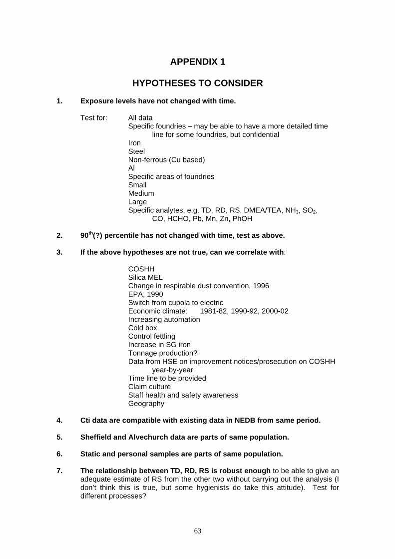
APPENDIX 1
HYPOTHESES TO CONSIDER 1. Exposure levels have not changed with time. Test for: All data Specific foundries – may be able to have a more detailed time line for some foundries, but confidential Iron Steel Non-ferrous (Cu based) Al Specific areas of foundries Small Medium Large Specific analytes, e.g. TD, RD, RS, DMEA/TEA, NH3, SO2, CO, HCHO, Pb, Mn, Zn, PhOH 2. 90th(?) percentile has not changed with time, test as above. 3. If the above hypotheses are not true, can we correlate with: COSHH Silica MEL Change in respirable dust convention, 1996 EPA, 1990 Switch from cupola to electric Economic climate: 1981-82, 1990-92, 2000-02 Increasing automation Cold box Control fettling Increase in SG iron Tonnage production? Data from HSE on improvement notices/prosecution on COSHH year-by-year Time line to be provided Claim culture Staff health and safety awareness Geography 4. Cti data are compatible with existing data in NEDB from same period. 5. Sheffield and Alvechurch data are parts of same population. 6. Static and personal samples are parts of same population. 7. The relationship between TD, RD, RS is robust enough to be able to give an
adequate estimate of RS from the other two without carrying out the analysis (I don’t think this is true, but some hygienists do take this attitude). Test for different processes?
63

64

APPENDIX 2
HISTORIC DATA PROJECT – ANALYTICAL TIME LINE
ALVECHURCH Alvechurch had its own laboratory from the start, which was used both to develop analytical methods for foundry use and to analyse collected samples. BCIRA developed personal cyclone samplers for TD, RD, RS during the late 1960’s. Prior to laboratory closure ,October 2001 TD, RD
• Prior to ~1970’s used Hexhlet (horizontal elutriator – high volume sampler) for respirable dust and silica.
• Personal cyclone used from mid 1970’s. Always used original cowled cyclone. RS
• Always used x-ray diffraction for silica (quartz and cristobalite) although IR was sometimes used for cross checking. Used X7488 standard for quartz.
TD+metals
• Used modified UKAEA 7-hole sampler. • Most metals by inductively coupled plasma emission spectrometry (icpes) but Pb was
done by atomic absorption spectrometry (AA). Other compounds were initially determined by indicator tubes but specific methods were developed and in place by mid-80’s. Only CO/SO2 continue to be detector tubes because there is no suitable chemical method.
• Amine – Acid impinger/ion chromatography • Phenol – Silica gel tube / HPLC • FA -Silica gel tube / GC • Formaldehyde – Water impinger / AHMT / colorimetry • MDI - Methanol impinger / HPLC • NH3 - Acid impinger / ion chromatography • Fluorides – Filter or alkaline impinger / ion chromatography • Other organics – Charcoal or silica tubes / gc
Post laboratory Closure Contract laboratories were used for analysis with often different (and sometimes untried) methods both for sampling and analysis. TD,RD
• No change RS
• Still xrd but initial problems dealing with graphite interference (temporary high detection limit ). Sorted fairly quickly. A9950 standard for quartz used.
65

TD+metals • Essentially no change although detection limits may be different. Pb now done with
others by ICP_ES. Other compounds
• Amine – XAD7 tube / gc • Phenol – XAD7 tube / hplc • FA – Charcoal tube / gc • HCHO – 2,4-DNP coated silica tube / HPLC • MDI – Treated filter to MDHS 25/3 • NH3 – Acid treated silica tube / ion chromatography • Fluorides – No change • Other organics – No change
SHEFFIELD RS
Mid 80’s to ~1992 – used bromide disc for IR detection of quartz and cristobalite. Very suspicious of sensitivities quoted, especially for cristobalite – no cristobalite and very little quartz ever detected. Not sure what standard used. From ~1992 – used Fourier transform IR directly on filters in-house by non-chemist technician, limited wavelengths. Probably only quartz but this should be fairly reliable. No procedures for determining cristobalite separately. Use A9950 standard for quartz, no cristobalite standard. - 1998/9/2000 – some samples giving interference by IR, sent to Alvechurch for x-ray. 2003 – agreed that dodgy samples should be sent for x-ray D. analysis.
TD/RD Use SIMPEDS cyclones – possibly more subject to interference than cowled version used at Alvechurch. Only grit pot and filter dust weighed
TD/metals As Alvechurch.
Amine Till ~2001 used NH3 diffusive detector tubes – may over-estimate due to interference from NH3. Post 2001 use XAD tubes/GC.
HCHO Was detector tubes/post 2001, now 2,4-DNP coated silica tube, as Alvechurch.
Phenol Was SiO2 NIOSH tube/GC, post 2001 XAD tube.
MDI ~1996-1999 – bubbler, as Alvechurch. Post 1999 – treated filter as Alvechurch.
NH3 Diffusive detector tubes.
Others As Alvechurch.
66

APPENDIX 3
FACTORS INFLUENCING PERSONAL EXPOSURES IN FOUNDRIES
FACTORS
Date of Introduction
Date of Implementation
Uptake Likely Effecton Exposure
New/Changing Technology: Mechanisation of greensand moulding lines - conventional boxed - vertically parted boxless
Late 30’s ~ 1975
Most implemented by mid 70’s Mainly mid 80’s but ongoing
High for long run larger medium castings V. high for long run smaller automotive castings
Dust exposure due to higher throughput unless enclosed/ extracted fully integrated automated knockout system Generally dust exposure although some vibratory shakeouts not well controlled
Introduction of chemically bonded sand for moulding - loss of dry sand process - furane - alkaline phenolic - CO2 silicate/ester silicate
50’s 60’s 80’s 50’s
Gone by 80’s Through 70’s complete by 80 90’s Declining by 70’s
High for small/medium jobbing foundries especially with loose pattern work Medium in some areas replaces silicate High initially, still used by some specialist foundries
Dust exposure at knockout SO2/HCHO/PhOH Dust HCHO/PhOH Dust High dust at knockout otherwise low exposure. CO2 if poor ventilation
67

New/Changing Technology cont…. Introduction of chemically bonded sand for moulding cont.. - polyurethane - shell - V process
Mid 70’s By 50’s 70’s
Mid 80’s 1950-1960 Late 70’s
Low except for Al. Often core assembly on tray core High for specialist long run smallish precision castings Low
High fume/smoke levels NH3/PhOH HCHO low High dust/smoke at knockout. High dust at moulding and post-casting
Introduction of core processes - furane - shell - hot box - cold box
60’s By 50’s 60’s Early 70’s
Through 70’s completed by 80’s 1950-1960 By 70 declined rapidly from late 80’s, replaced by cold box From 80’s core assembly from mid 90’s
Med. for large cores in big castings. Also for system sand High but declining through 90’s. Replaced by cold box High – cheaper than shell High and increasing
SO2/HCHO/PhOH Dust NH3/Phenol High smoke/ fume HCHO NH3 Amine especially at assembly due to retention in large cores. Lot of fume from core assembly but no problem from cores in sand
68

New/Changing Technology cont…. Introduction of core processes cont.. - alkaline phenolic - CO2 silicate
80’s 50’s
Mid 80’s 50’s
Low impact, less obnoxious than cold box but not as good High, declining since 70’s, replaced by cold box
Dust at shakeout and decore
FACTORS
Date of Introduction
Date of Implementation
Uptake Likely Effecton Exposure
Improved Control: Extraction at vibratory shakeout - greensand - attrition reclaim - partial thermal reclaim - sand plant improvement, reduction of spillage
Common by 60’s Late 70’s Late 90’s 70’s
Extraction rates/ enclosure increased to present Mid to late 90’s (Landfill tax) Flat belt trough continuous to present Extraction at transfer from 70’s
High Moderate Low Fairly high
Dust Dust at knockout Fume/SO2 at casting Reduce SO2 Background dust levels
69

Improved Control: cont… Extracted fettling benches 40’s 50-60 but poor
effective in 1990’s High Dust
Extracted fettling - hole in floor downdraught - low profile booths - walk-in booth - on tool extraction - stand grinder - SF grinder
- portable
50’s by 60’s Late 70’s 80’s 70’s extraction rate to present 80’s 80’s
Moderate High Low High Moderate Very low
Minimal Minimal – not used properly Dust if adequate extraction Dust Dust - often non-shotblasted casting-large Dust
Extracted casting track Drivers – EPA and COSHH for track systems
50’s
Gradual to present
Mod. high for chem. bond, less for greensand
Fume (inc SO2/CO) CO
Extraction on electric furnaces - roof fans - canopy hoods - side draft - close capture
Always ) Gradual increase ) 80’s
90’s onwards
High High for small furnaces Moderate for larger furnaces High for large/new furnaces
Prevent build-up of metal fume Prevent fume build-up Some fume Fume
70

Improved Control: cont… Extraction of shell/hot box machines - actual machine - cooling/dressing station - gluing stations
Mid 70’s Mid 80’s
Mid 80’s onwards esp for shell moulding and new machines Mid 80’s onwards
Fairly high esp for shell moulding Patchy Patchy
NH3/HCHO/PhOH
Extraction of cold box machines - dressing/assembly stations
~ 1980 Complete mid 80’s 90’s
High Low
) ) Amine )
Cooling tunnels for chemically bonded especially furane - greensand moulds
60 More post COSHH 80’s
Fairly high Moderate
Fume level/CO/SO2
Extraction at mixer head, esp furane Late 70’s to remove H2SO4 aerosol
Still increasing
Low
H2SO4 FA ?
Mechanical Sweeping, Drivers:COSHH & EPA
80’s Mid 90’s Fairly high Background dust
Personal RPE - nuisance disposables - Type 2/FFP2 disposables - air stream helmets - other powered helmet/visor - other, mainly fume/organics
40’s 60’s Late 70’s 90’s
80’s, decrease post COSHH Mainly post COSHH Mainly post COSHH 90’s Post COSHH
High ) High in some ) sectors esp ) fettling Very low
71

FACTORS
Periods of Recession:
1973
1980-81 Many closures – rationalisation removed many small foundries
1990-91 Some closures
2001-2002 Many closures including some large/good foundries – castings
outsourced from abroad
General Effects of Recession on Exposure:
• Housekeeping improved during slight/short recession
• Investment in monitoring/health and safety equipment
• In more severe cases staffing reduction leads to poor housekeeping and double shifting
(increased exposure time)
• As production exposure generally
General Trends in Foundries:
Effects on Exposure:
Industry generally deskilled
Tendency to older population (although not always)
Experienced ? Personnel? Resistant to change?
Increase in H & S awareness from Unions and COSHH monitoring
Higher expectations – workforce driving better control
Trend to automatic pouring over whole period
Reduced fume/burns/heat stress
72

APPENDIX 4 Table 4.1: Database summary Foundries, forges etc Non-foundries Sic Codes 2751, 2752, 2753,
2754, 2840, 2873, 2875
1513, 2051, 2222, 2414, 2522, 2523, 2615, 2626, 2653, 2710, 2711, 2712, 2713, 2714, 2715, 2716, 2734, 2742, 2811, 2821, 2874, 2956,
2430/1, 2912/1 No of sites 260 27 No of samples 49787 1370
Table 4.2: Database summary: No of samples per analyte per SIC code for the Foundry/Forges Codes
SIC codes
Substance
2751 2752 2753 2754 2840 2873 Grand Total
1,1,1-Trichloroethane 7 35 10 2 54
1-Methoxypropyl acetate 4 4
2-Butoxyethanol 1 2 1 4
2-Ethoxyethanol 2 2
2-Methylheptane 1 1
2-Methylpropan-1-ol 1 2 3
3-Methylheptane 1 1
4-Hydroxy-4-methyl pentan-2-one 1 1
4-Methylpentan-2-one 1 1
Acetic acid 1 1
Acetone 2 11 13
Acrylaldehyde 2 2
Allyl alcohol 2 2
Aluminium 3 9 6 10 28
Ammonia 533 348 64 47 992
Antimony 19 47 1 15 5 87
Arsenic 19 48 2 4 1 74
Asbestos 14 4 18
Asbestos (crysotile) 1 1
Benzene 58 36 7 101
Benzoyl peroxide 2 2
Bismuth 28 39 1 5 4 77
Butan-1-ol 2 1 3
Butan-2-one 1 8 9
Butyl acetate 3 3
Butyl alcohol 1 1
Butyrolactone 2 2
Cadmium 75 16 6 97
Calcium 1 1
Calcium carbide 3 3
Calcium fluoride 6 6
Calcium oxide 6 6
Carbon dioxide 154 94 50 1 299
73

SIC codes
Substance
2751 2752 2753 2754 2840 2873 Grand Total
Carbon monoxide 1047 1360 124 44 5 2580
Carbon tetrachloride 2 2
Chromium 144 286 4 12 18 464
Chromium (VI) 5 1 3 2 11
Coal tar pitch volatiles 7 7
Cobalt 11 51 2 2 66
Copper 43 69 4 74 2 192
Cresols 9 4 6 19
Cumene 11 11
Cyclohexane 1 1
Diaminophenylmethane 2 2
Dichlorobenzene 2 2
Dichloromethane 5 11 16
Diethylbenzene 1 1
Dimethyl gluterate 1 1
Dimethylcyclohexane 1 1
Dimethylethylamine 199 4 203
Dodecane 1 1
Ethanol 1 37 38
Ethoxypropanol 1 1
Ethyl acetate 1 1 2
Ethylbenzene 3 3 Ferrous foundry particulate (respirable) 1744 1751 14 3509 Ferrous foundry particulate (total inhalable) 1940 2088 15 2 4045
Fluoride 7 1 17 1 2 28
Formaldehyde 581 655 98 38 1372
Furane derivatives 1 1
Furfuryl alcohol 167 100 15 5 287
Germanium 3 3
Heptane 1 1
Hexachloroethane 1 1
Hexadecane 1 1
Hydrocarbon solvents 12 12 4 3 31
Hydrogen chloride 3 2 1 6
Hydrogen cyanide 1 1
Hydrogen fluoride 4 4
Hydrogen sulphide 42 10 52
Indium 4 9 5 18
Iron 304 250 7 23 22 606
Iso butane 1 1
Kerosene 1 1
Lead 324 141 4 132 7 1 609
Magnesium 171 193 11 17 6 398
Manganese 197 263 8 3 471
74
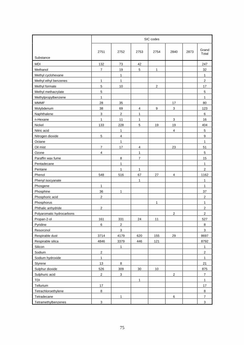
SIC codes
Substance
2751 2752 2753 2754 2840 2873 Grand Total
MDI 132 73 42 247
Methanol 7 19 5 1 32
Methyl cyclohexane 1 1
Methyl ethyl benzenes 1 1 2
Methyl formate 5 10 2 17
Methyl methacrylate 5 5
Methylpropylbenzene 1 1
MMMF 28 35 17 80
Molybdenum 38 69 4 9 3 123
Naphthalene 3 2 1 6
n-Hexane 1 11 1 3 16
Nickel 133 228 5 19 19 404
Nitric acid 1 4 5
Nitrogen dioxide 5 4 9
Octane 1 1
Oil mist 7 17 4 23 51
Ozone 4 1 5
Paraffin wax fume 8 7 15
Pentadecane 1 1
Pentane 1 1 2
Phenol 548 516 67 27 4 1162
Phenyl isocyanate 1 1
Phosgene 1 1
Phosphine 36 1 37
Phosphoric acid 2 2
Phosphorus 1 1
Phthalic anhydride 2 2
Polyaromatic hydrocarbons 2 2
Propan-2-ol 161 331 24 11 527
Pyridine 6 2 8
Resorcinol 3 3
Respirable dust 3714 4179 620 155 29 8697
Respirable silica 4846 3379 446 121 8792
Silicon 1 1
Sodium 2 2
Sodium hydroxide 1 1
Styrene 13 8 21
Sulphur dioxide 526 309 30 10 875
Sulphuric acid 2 3 2 7
TDI 1 1
Tellurium 17 17
Tetrachloroethylene 8 8
Tetradecane 1 6 7
Tetramethylbenzenes 3 3
75

SIC codes
Substance
2751 2752 2753 2754 2840 2873 Grand Total
Thorium 3 3
Tin 33 61 3 38 1 136
Titanium 18 71 4 2 4 99
Toluene 72 54 6 8 140
Total inhalable dust 3859 4448 675 303 145 1 9431
Trichloroethylene 3 14 5 1 23
Tridecane 1 6 7
Triethylamine 90 115 42 247
Trimethylbenzenes 20 16 5 41
Tungsten 2 2
Vanadium 21 50 1 6 6 84
Welding fume 71 258 14 2 6 351
White spirit 7 19 1 3 30
Wood dust 89 155 5 4 26 279
Xylene 40 7 10 57
Xylene sulphonic acid 1 1
Xylenes 77 102 6 185
Xylenols 1 4 5
Zinc 236 185 11 57 4 493
Zirconium 3 3
Grand Total 22826 22786 2532 1224 417 2 49787
76

Table 4.3: Database Summary: No of samples per analytes per non-Foundry/Forges SIC codes
SIC Codes
Substance
1513
2051
2222
2414
2522
2523
2615
2626
2653
2710
2711
2712
2713
2714
2715
2716
2734
2742
2811
2821
2874
2956
2430
/1
2912
/1
Gra
nd
Tota
l
1,1,1-Trichloroethane 3 3 2-Butoxyethanol 8 8 2-Ethoxyethanol 8 8 4-Methylpentan-2-one 1 1Acetone 5 6 1 Aluminium 2 2 5 1 Ammonia 12 12 Antimony 3 3 Arsenic 2 2 Bismuth 3 3 Butan-1-ol 3 4 7Butan-2-ol 3 3 Butan-2-one 1 1 Butyl acetate 1 4 5Cadmium 3 3 Carbon dioxide 12 12 Carbon monoxide 12 26 1 1 1 1 1 3 18 1 9 8 82Chloride 2 2 Chromium 3 1 6 2 Cobalt 2 3 1 Copper 3 3 13 1 20Cresols 8 8 Dibutyl phthalate 3 3Dichloromethane 11 1 12Ethanol 5 5 Ethoxypropanol 8 8 Ethyl acetate 1 4 5Ferrous foundry particulate (total inhalable) 3 3 Flour dust 18 18 Fluoride 2 3 5 Formaldehyde 2 2 Heptane 1 1 Hydrocarbon solvents 1 1Iron 12 3 1 16Lead 16 9 2 12 1 40Magnesium 9 2 14 3 Manganese 1 2 3 6MDI 6 6 Methanol 2 4 2 Methyl cyclohexane 1 1 Molybdenum 4 4 Naphthalene 2 2
77

SIC Codes
Substance
1513
2051
2222
2414
2522
2523
2615
2626
2653
2710
2711
2712
2713
2714
2715
2716
2734
2742
2811
2821
2874
2956
2430
/1
2912
/1
Gra
nd
Tota
l
Nickel 4 1 8 3 Nut dust 2 2 Oil mist 12 12 Ozone 1 1 Peanut protein 2 2 Phenol 6 4 2 Propan-2-ol 1 5 6 Respirable dust 15 5 5 6 7 96 104 5 25 2 22 8 33 333Respirable silica 42 13 8 63Sulphur dioxide 4 4 Tetramethylbenzenes 3 3Tin 5 6 1 Titanium 13 16 3 Toluene 2 1 5 3 11Total inhalable dust 27 6 6 23 98 2 133 11 1 39 4 29 1 8 34 422Trichloroethylene 1 3 4Triethylamine 1 1 Trimethylbenzenes 3 4 1 Tungsten 2 2 Vanadium 4 1 7 2 Welding fume 3 16 19 White spirit 1 4 4 9 Wood dust 25 27 2 Xylene 2 1 9 12Xylenes 3 9 12 Xylenols 3 3 Zinc 12 1 16 3 Grand Total 88 36 10 30 12 17 46 245 6 364 1 1 1 1 1 47 2 142 10 6 114 1 70 119 1370
78

APPENDIX 5
Useful job groupings for analysing trends in exposure Some jobs should be grouped by job, i.e.: Group 1 – Wrecking:
Furnace wrecking Cupola fettle Ladle dressing
Group 2 – Thermal Cutting:
Arc/air cutting Powder burning Powder cutting auto Powder cutting manual Oxy acetylene cutting Welding Welding aluminium
Group 3a – Fettling:
Auto fettle load Auto fettle unload Chipping De-flash Grinding (disc) Grinding (wheel) Grinding (belt) Grinding (surface) Grinding (disc) aluminium Grinding (disc) LG2 Swing frame grinder
Group 3b – Other Finishing:
Cutting wheel Cut-off saw Knock-off Rake-off Shot blast Shot blast load Shot blast unload Sort belt Wire brushing
79

Others can reasonably be grouped by UProcess That is; Group 4 – Moulding and Coremaking:
(Core and Mould Production) (Mould Production )
Group 5 – Melting:
Melting Size Grouping by Head Count: < 50 Small 51 < size < 150 Small medium 151 < size < 250 Large medium 251 < size Large
80

APPENDIX 6
PIVOT TABLES This Appendix is intended to introduce an analyst to some useful techniques learned during the project in order to extract data, for example, where samples of different analytes are from the same sample but have been entered as separate entries into an NEDB type database. Although quite detailed, these notes are intended for use by an operator who is familiar with MS Excel with some experience and are not intended to direct the novice. This section will highlight how to use the PivotTable function to isolate individual data by the use of the unique labels. The aim is to extract results for a sample through having a ‘link (LK)’ number, e.g. where Total Dust, Respirable Dust and Respirable Silica were all taken from the same sample but each result is on its own line (see Figure 1).
Figure 1: Lines of data from the database where ‘linked’ samples are on separate lines
In this form these related data cannot be related to each other for the purposes of statistics or graph plotting. A ‘PivotTable’ was used to allow all these analytes to be sorted onto one data line (see Figure 2).
Field labels
PivotTable Menu
Figure 2: Example of a ‘unique sample reference’ using field labels
A “PivotTable” can summarise all results with the same field label or set of field labels. In this case a field label is: date, ID (site i.d. number), job name, process name and link number.
81

These multiple fields can be used to construct a unique label for each sample, with only the analyte differing, as in the example in Figure 2 where the “Visit Date”, the “ID”, the “Job Name”, “Process Name” and “LK” labels create a unique reference. In this example, only one data line is shown for ease, however this process would normally create a database sorted by these field labels. In order to extract the data, these steps are followed: • “PivotTable” function is found in the “Data” menu under “PivotTable and PivotChart
Report”. • Using the “PivotTable Wizard” - select “Microsoft Excel List or Database” “PivotTable”. • Select the range (should automatically set the range for all the data on the current
worksheet). • Select “new Worksheet”. And “Finish”. • Open “PivotTable Toolbar” and open “PivotTable Field List”. In some versions of Excel it
automatically opens. • Drag field labels from the “PivotTable Menu” and drop them into the “PivotTable”, as seen
in Figure 3. On the “PivotTable Menu” are the items with which to build table.
Figure 3: Construction of the PivotTable using menu • The data to be summarised should be entered into “Drop Data Items Here” • the reference defined should be created by repeatedly dropping the labels in “Drop Row
Fields Here” • the different types of result that the reference defines (in this case by “substance”) the
“Label” should be dropped in the “Drop Column Fields Here”. • Put result into “drop data items here”
82

• In column under A3 sum of result i.e. A4 • Substance goes into B3 • A sample can most easily be defined by Id, Date, Job name, link number, which are the
categories that are the most common and useful. • Set “A3” by double clicking to set as “Count result”. Check the number of entries per cell
first. There should only be one entry per cell (see Figure 4) otherwise it will sum those entries in the cell and give incorrect answer.
Cell A3
Figure 4: Example showing the ‘Count’ function of “PivotTable” to ensure
only one entry per result cell Figure 5 shows the “Sum of Results” instead of displaying the “Counts of Results”. To do this, Set A3 by double clicking to set as “Sum of Result”. This will display the result for each cell bearing the reference, this should be the sum of only one cell bearing that reference.
Figure 5: Example showing the completed PivotTable in a form not suitable for use with MINITAB
The data in the PivotTable is not in a form that is directly transferable to MINITAB: it needs to be transferred to a form that can be used in MINITAB. Unfortunately the “PivotTable” process means that each line no longer has all the data associated with the result, as seen in the ID column, whereas all data to the right of the column is associated (see Figure 6).
83

Full label
No label
Figure 6: “PivotTable” “Cut and Pasted” (values only) to a new worksheet, but not suitable for use with MINITAB
The data can be filled in using a simple logic function which can be cut and pasted into a new column (see Figure 7). It can be seen in Figure 7 that extra columns have been inserted as has the logic function “=IF(B10=0,C9,B10)”. This asks, for the date column, “if the visit date is blank i.e. equal to 0, then read the above cell (where the function is written), otherwise read the date cell”. This is repeated for the other columns. This database is now suitable for interrogation using MINITAB.
B10 C9
Figure 7: Table containing data suitable for interrogation by/exportation to MINITAB, showing formula for ‘filling in the gaps’
84

BIBLIOGRAPHY AND REFERENCES Chisholm J 2004 Health and Safety Laboratory, personal communication. HSE 2000 Pre-Regulatory Impact Assessment consultation on occupational exposure to manganese and its inorganic compounds 2000/2001 (contact: J Healy) Isherwood SA 1986 Chemical analysis and mutagenic activity of foundry casting fume HSE Projects 48.18 & 48.11. Levy L et al. 1994 The potential carcinogenicity of foundry fumes 1994 published in Smillie MV et al. 1994 Criteria document to review effects on health of airborne substances in the ferrous foundry environment. HSE Contract Research Report No 65. HSE Books. Sic 2003 UK Standard Industrial Classification of Economic Activities METHODS FOR DETERMINING HAZARDOUS SUBSTANCES Published by HSE Books MDHS 14 General methods for the sampling and gravimetric analysis of total and respirable dust (various versions and dates- latest MDHS14/3 2000) MDHS-25/3 Organic isocyanates in air. Laboratory method using sampling either onto 1-(2-methoxyphenyl)piperazine coated glass fibre filters followed by solvent desorption or into impingers and analysis using high performance liquid chromatography. 1999 MDHS 37 Quartz in respirable airborne dusts. Laboratory method using infra-red spectroscopy (direct method).1987 MDHS 38 Quartz in respirable airborne dusts. Laboratory method using infra-red spectroscopy (K Br disc method).1984 MDHS 51/2 Quartz in respirable airborne dust.Laboratory method using x-ray diffraction 1988 MDHS 76 Cristobalite in respirable airborne dusts. Laboratory method using x-ray diffraction. 1994
85

86

GLOSSARY OF FOUNDRY TERMS
Bead blast: a version of shot blast mainly for light metals using glass beads or alumina/zirconia granules instead of steel shot.
Binder: a chemical added to sand to make the grains hold together for moulding or
core making. Casting: a metal object made by pouring molten metal into a mould where it solidifies in
a pre-determined shape. Also the act of pouring molten metal into a mould. Cope: the top half of a mould. Core: a piece of hardened sand placed in a mould to produce a hollow in the casting. Corebox: the wooden or metal mould in which cores are made. Core print: a projection on a pattern which makes an impression in the mould in which a
core rests. Cut-off: removal of runner system from a casting by thermal or mechanical cutting. Die casting: pouring molten metal into a permanent mould made of metal - usually for non-
ferrous foundries. Downgate: the main channel down which molten metal is poured into the mould cavity. Drag: the bottom half of the mould. Feeder: a channel in the mould to supply molten metal to replace that lost by shrinkage
as the casting solidifies. Ferrous: concerned with or made of iron or steel. Fettling: removing pieces of surplus metal from a casting. Flash: thin pieces of metal projecting from an unfettled casting; caused by molten
metal seeping from the mould cavity between two parts of a mould/core assembly.
Foundry: a place where castings are made. Greensand: damp clay bonded moulding sand which makes a firm mould without having to
be specially treated. Ingate: channels in the bottom half of a mould which supply the mould cavity. Investment a foundry where the casting shape is modelled in wax or polystyrene Foundry: and this model is then coated in refractory applied as a slurry. The model is then
melted or burnt out and the mould poured.
87

Joint line: the line indicating the join between two halves of a pattern which are moulded separately in two moulding boxes.
Knock-off: removal of runner system from a casting by impact. Knockout: separating moulding and core sand from a solidified casting. Ladle: a container used to carry molten metal from the furnace to the mould. Mould: a hollow made in bonded sand (usually) into which molten metal is poured to
make a casting. Moulding a rigid frame which holds the sand in which a mould is made. box: Non-ferrous: non-iron metals - includes light alloys such as aluminium, magnesium and zinc
and copper based metals such as brass, bronze and gun metal. Pattern: a model made of wood, metal or resin, used to make moulds for castings. Refractory: noun or adjective - a material which will stand up to high temperatures. Running the set of channels in a mould through which metal is poured to fill the system: mould cavity. Shakeout: knockout carried out mechanically by a vibrating grid or rotating drum. Shot blast: removal of residual adhering sand from solidified castings using jets of steel shot.
88

ABBREVIATIONS ACGIH American Conference of Governmental Industrial Hygienists AHMT 4-Amino-3-hydrazino-5-mercapto-1,2,4-triazole (Purpald) BCIRA British Cast Iron Research Association CEN Comite Europeen de Normalisation CHAN Chemical Hazard Alert Notice CO Carbon monoxide CO2 Carbon dioxide COSHH Control of Substances Hazardous to Health Regulations Cti Castings Technology International 2,4-DNP 2,4-Dinitrophenylhydrazine DMEA Dimethylethylamine EPA Environmental Protection Act FA Furfuryl alcohol FFP Ferrous foundry particulate FTIR Fourier transform infra red GC Gas chromatography HASAWA Health and Safety at Work etc. Act HCHO Formaldehyde HPLC High performance liquid chromatography HSE Health and Safety Executive HSL Health and Safety Laboratory, Buxton IARC International Agency for Research on Cancer IOM Institute of Occupational Medicine, Edinburgh IR Infra red KBr Potassium bromide LEV Local exhaust ventilation MEL Maximum Exposure Limit MDI Methylene diphenyl diisocyanate MDHS Method for Determining Hazardous Substances Mn Manganese NEDB National Exposure Data Base NH3 Ammonia NIOSH National Institute for Occupational Safety and Health (USA) ODBC Open database connectivity OES Occupational Exposure Standard OSHA Occupational Safety and Health Administration Pb Lead PhOH Phenol QA Quality assurance RD Respirable dust RPE Respiratory protective equipment RS Respirable silica RIA Regulatory Impact Assessment SCRATA Steel Castings Research and Trade Association SG Spheroidal graphite SIC Standard Industrial Classification SiO2 Silicon dioxide (silica )SO2 Sulphur dioxide TD Total dust
89

TDI Toluene diisocyanate TEA Triethylamine TWA Time Weighted Average UKAEA United kingdom Atomic Energy Authority UKAS United Kingdom Accreditation Service WEL Workplace Exposure Limit XRD X-ray diffraction Zn Zinc
90

91

Printed and published by the Health and Safety ExecutiveC30 1/98
Printed and published by the Health and Safety ExecutiveC1.10 07/05

RR 374
£25.00 9 78071 7 661 5 1 0
ISBN 0-7176-6151-2