research report ktc-05-04/spr 180-98-1f kentucky...
TRANSCRIPT

K
T
C
ENTUCKY
RANSPORTATION
ENTER
College of Engineering
EXAMINATION OF ECONOMICAL METHODS
FOR REPAIRING HIGHWAY LANDSLIDES
Research Report
KTC-05-04/SPR 180-98-1F

For more information or a complete publication list, contact us
176 Raymond Building
University of Kentucky
Lexington, Kentucky 40506-0281
(859) 257-4513
(859) 257-1815 (FAX)
1-800-432-0719
www.ktc.uky.edu
We provide services to the transportation community
through research, technology transfer and education.
We create and participate in partnerships to promote
safe and effective transportation systems.
Our Mission
We Value...
Teamwork -- Listening and Communicating, Along with Courtesy and Respect for Others
Honesty and Ethical Behavior
Delivering the Highest Quality Products and Services
Continuous Improvement in All That We Do
KENTUCKY TRANSPORTATION CENTER
The University of Kentucky is an Equal Opportunity Organization

Research Report KTC-05-04/SPR-180-98-1F KYSPR-180-98-1F
EXAMINATION OF ECONOMICAL
METHODS FOR REPAIRING HIGHWAY LANDSLIDES
by Liecheng Sun Tommy C. Hopkins Tony L. Beckham Research Engineer Senior Chief Research Engineer Research Geologist
and
Bixian Ni Former Associate Research Engineer
Kentucky Transportation Center College of Engineering University of Kentucky
in cooperation with the Kentucky Transportation Cabinet The Commonwealth of Kentucky
and Federal Highway Administration
The contents of this report reflect the views of the authors, who are responsible for the facts and accuracy of the data herein. The contents do not necessarily reflect the official views or policies of the University of Kentucky, Kentucky Transportation Cabinet, nor the Federal Highway Administration. This report does not constitute a standard, specification, or regulation.
April 2005


Abstract iii
1. Report No. KTC- 05-04/SPR-180-98-1F
2. Government Accession No.
3. Recipient’s Catalog No. 5. Report Date
April 2005 6. Performing Organization Code
4. Title and Subtitle EXAMINATION OF ECONOMICAL METHODS FOR REPAIRING HIGHWAY LANDSLIDES
8. Performing Organization Report No. KTC- 05-04/SPR-180-98-1F
7. Authors Charlie Sun, Tommy C. Hopkins, Tony L. Beckham, and Bixain Ni
10. Work Unit No. (TRIAS)
9. Performing Organization Name and Address University of Kentucky College of Engineering Kentucky Transportation Center 176 Oliver Raymond Building Lexington, KY 40506-0281
11. Contract or Grant No. KY SPR-180-98-1F
13. Type of Report and Period Covered Final---SPR-180-98-1F
12. Sponsoring Agency Name and Address Kentucky Transportation Cabinet 200 Mero Street Frankfort, KY 40622 14.Sponsoring Agency Code
15. Supplementary Notes
Prepared in cooperation with the Federal Highway Administration, US Department of Transportation 16. Abstract The Kentucky Transportation Cabinet spends millions of dollars each year in the repairs of highway landslides. In previous research, an inventory of highway landslides showed that about 1440 landslides of various sizes exist on major roadways maintained by the Kentucky Transportation Cabinet. Moreover, emergency repairs can exceed one million dollars for large embankment failures. In many instances, drilled-in, or driven, railroad steel rails were frequently used as a stop-gap measure to halt landslide movements or those efforts were tried as a permanent solution. The use of rails to serve as a restraining structure was usually not successful when the height of fill exceeded about 20 feet. The previous study also showed about 39 percent of the landslides were small and less than 20 feet in height. Cost estimates indicated that railroad steel rails, when drilled and socketed into bedrock, may be effective and economical when the embankment height is less than about 20 feet. This study had two major objectives. Because railroad steel rails are widely used, the development of a theoretical method of analyzing and predicting the success of rails that are drilled-in and socketed into bedrock was a major objective. To enhance this method and possibly extend the height that this technique may be used, theoretical equations were developed that include the use of lightweight backfill materials, such as geofoam, shedded tires, bundled tires, “red dog,” and byproducts from coal-fired power plants. Backfill materials with different unit weights, and existing in a layered system, may be analyzed. To facilitate the use of the approach and make it widely accessible to Cabinet engineers, and as a second major objective, the theoretical algorithms were programmed in a windows computer program and stored in the Kentucky Geotechnical Database. The twelve highway district offices and main central offices of the Cabinet are connected in a client server system. For a selected factor of safety, the program predicts the success of drilled-in rails so that the user may avoid using this technique when the factor of safety is not adequate to prevent failure. However, when failure is predicted using the unit weights of ordinary soil, or rock, backfill, the program shows the thickness of geofoam (or other lightweight material) necessary to increase the factor of safety to value greaten than one. The program has been checked by comparing results with results obtained from a program written by KyTC. Several examples are performed to illustrate the use of the new computer program. 17. Key Words
Highways, Railroad Rails, landslides, Repairs, Economics, Soils, Theoretical Model, Light-weight Materials.
18. Distribution Statement Unlimited, with approval of the Kentucky Transportation Cabinet
19. Security Classification (of this report) None
20. Security Classification (of this page) None
21. No. of Pages 23
22. Price
Form DOT 1700.7 (8-72)Reproduction of completed page authorized


Table of Contents v
TABLE OF CONTENTS
LIST OF FIGURES ............................................................................................................................vii LIST OF TABLES ............................................................................................................................... ix EXECUTIVE SUMMARY ..................................................................................................................xi INTRODUCTION ................................................................................................................................ 1 OBJECTIVES AND SCOPE................................................................................................................. 3 GENERAL FEATURES OF HIGHWAY LANDSLIDES IN KENTUCKY ....................................... 4 APPLICATION OF GEOFOAM IN REPAIRING HIGHWAY LANDSLIDES................................. 7
Properties of Geofoam ............................................................................................................. 7 Landslide in Kentucky Highway.............................................................................................. 7
Physical Models of Landslide Retaining System..................................................................... 8 Implementation Under GUI Environment........................................................................... 13
Comparing with CTBRAIL Rail Design Program Developed by KyTC.......................... 15
Examples: Analyzing Retaining Wall with different Lightweight Materials ................... 18
SUMMARY AND CONCLUSIONS ................................................................................................. 20 REFERENCES .................................................................................................................................... 22


List of Figures vii
LIST OF FIGURES Figure 1. Massive highway embankment failure on a parkway route in Butler County—
repair cost was 1.4 million dollars .......................................................................................... 1 Figure 2. Use of asphaltic patching overlays to maintain grade elevation at a landslide
(total thickness of patching is about 5 feet)............................................................................ 2 Figure 3. General slope condition and associated cost category (data compiled by the
Geotechnical Branch of Materials, of the Kentucky Transportation Cabinet.).................... 3 Figure 4. Severity ratings of highway landslides in Kentucky .......................................................... 4 Figure 5. General heights of highway landslides in Kentucky .......................................................... 5 Figure 6. Highway embankment failure on KY 847 in Owsley County........................................... 6 Figure 7. Attempts to halt highway failure using railroad steel rails ............................................... 6 Figure 8. Landslide retaining system model 1, Level Backfill .......................................................... 9 Figure 9. Landslide retaining system model 2, Sloping Backfill ...................................................... 9 Figure 10. Landslide retaining system model 3, Broken Backslope ............................................... 10 Figure 11. Distribution of the horizontal stress along the rail pile .................................................. 11 Figure 12. Resultant force of the horizontal stress for one typical segment on the rail pile.......... 13 Figure 13. Friendly graphical user interface for landslide retaining wall analysis......................... 14 Figure 14. Detail information shows up by moving mouse to one point ........................................ 15 Figure 15. A detail design sheet shows up by clicking a point on analyzing curve....................... 16 Figure 16. Data input sheet for corresponding retaining model ...................................................... 16 Figure 17. Property input sheet for selected lightweight materials ................................................. 17 Figure 18. Data input sheet for selected rail pile .............................................................................. 17


List of Tables ix
LIST OF TABLES
Table 1. Comparison of Safety Factors Between Progrms Developed by KyTC and UKTC ......18 Table 2. Comparison of Thickness between Different Lightweight Materials with Safety
Factor ≈ 1.4, Without Water Table ....................................................................................19 Table 3. Comparison of Thickness between Different Lightweight Materials with Safety
Factor ≈ 1.4, With Water Table .........................................................................................19 Table 4. Safety Check When Pavement is Immersed under Water for Three Typical
Lightweight Materials........................................................................................................20


Executive Summary
xi
EXECUTIVE SUMMARY
This study briefly describes the current status of landslides on the Kentucky highway system. As Kentucky’s roadways increase in age, highway embankments and cut slopes deteriorate and frequently collapse. Each year, the Kentucky Transportation Cabinet spends millions of dollars repairing highway landslides. To insure the safe movement of traffic through areas of active movements, maintenance crews patch the settled roadway frequently to maintain grade elevation. Unfortunately, this very costly technique does not repair the landslide and often accelerates movement with the added weight. Because of the large number of landslides and the enormous costs involved methods that might prove to be economical need to be examined. Railroad piles have been used frequently to repair landslides. This repair method, however, has not solved most landslide problems in Kentucky (and elsewhere in the country). The main reason could be that railroad piles cannot always withstand the horizontal stress from the displacement of clayey shales that commonly have high lateral stress coefficients. Additionally, the railroad piles at old sites were oftentimes not anchored, or socketed into bedrock, or a firm material, below the slip surface. Geofoam is the generic name for any foam material used in a geotechnical (on- or in-ground) application. The term geofoam has only been used since 1992. However, foams have been used successfully in geotechnical applications since at least the mid 1960s. Geofoam is very light material. Its dry unit weight ranges from 0.35 to 2.5 lb/ft3. It will absorb small amount of water when it is placed under the water table in subsoil. Experiments showed that the wet density of geofoam is lower than 4.0 lb/ft3, even under a saturated condition, and it is still much lighter than any lightweight foundation material. When a vertical load is applied to a material, the material will transfer some horizontal stress to the surrounded area. The ratio of the horizontal stress to the vertical stress is called the lateral stress coefficient. Experiments have shown that the lateral stress coefficient of geofoam ranges from 0.2 to 0.4, which is much lower than that of soil. Lateral stress coefficient of soil varies from 0.3 to 1.0. This makes geofoam material an ideal material for filling behind the retaining walls. Combination of geofoam and railroad piles could provide a solution for repairing small highway landslides. In this report, three highway retaining system models are described. These include the Level Backfill model, Sloping Backfill model, and Broken Backfill model. These models have been analyzed theoretically. The lightweight material played a significant role for these landslide retaining system repair models. By using Rankine’s and Coulomb’s active pressure theories, a linear distribution for both vertical and horizontal stresses is assumed. Theoretical equations have been derived for multi-layer retaining wall system based on this assumption. Using derived equations, a curve of safety factor as a function of geofoam thickness is obtained for any given case. Based on that relationship, a safety factor required for stability of the landslide retaining wall system the thickness of geofoam may be established. Using PowerBuilder software over a Windows platform, the theory presented above is built into an event driven program with friendly Graphical User Interface (GUI). Comparison of Safety Factors obtained by programs developed by KyTC and based on this theory has shown identical results for models of Level Backfill and Sloping Backfill. This comparison shows some differences that varied from 4.0% to 7.61%, for the Broken Backslope model. The higher the retaining wall, the smaller the difference between results from those two programs. The result obtained by program based on theoretical analysis is more conservative comparing with result calculated by a KyTC program.

Executive Summary
xii
This study provided three different cases involving the water table located behind the pile rail wall. This included a wall without water table, a wall with partial water table, and a completely immersed water table. Example of each case is presented. Results obtained from examples in this report indicate that unit weight of backfill material plays a considerable roll for the retaining system. Results obtained from the newly developed computer program are slightly more conservative than results obtained from the MS Excel program developed by KyTC. No comparisons of cases involving layered backfill with different strength properties could be made since the KyTC program only solves the case involving one layer of backfill. The heavier material, the larger thickness of light material is required. The geofoam is the best candidate for landslide retaining wall system due to its light unit weight. Also, the program developed in this report can predict maximum thicknesses of lightweight material without any buoyant force. If thickness is greater than the maximum thickness predicted, the pavement will be damaged by buoyant force. This provides a convenient tool to design highway landslide retaining systems for areas with high water tables. To the knowledge of the authors, this computer program is the only one available for analyzing multi-layer landslide retaining wall systems. It is a convenient tool with friendly Graphical User Interface (GUI) for highway landslide retaining system involving more than one layer. Real job sites are expected to verify this theoretical approach.
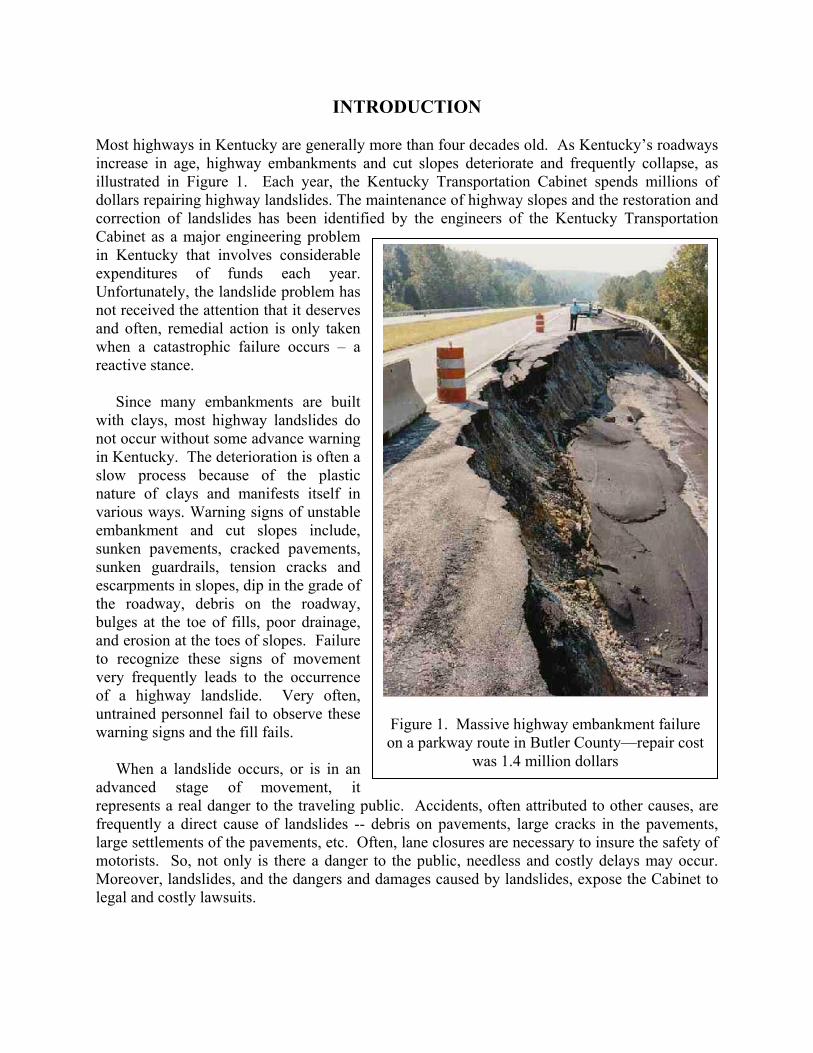
INTRODUCTION
Most highways in Kentucky are generally more than four decades old. As Kentucky’s roadways increase in age, highway embankments and cut slopes deteriorate and frequently collapse, as illustrated in Figure 1. Each year, the Kentucky Transportation Cabinet spends millions of dollars repairing highway landslides. The maintenance of highway slopes and the restoration and correction of landslides has been identified by the engineers of the Kentucky Transportation Cabinet as a major engineering problem in Kentucky that involves considerable expenditures of funds each year. Unfortunately, the landslide problem has not received the attention that it deserves and often, remedial action is only taken when a catastrophic failure occurs – a reactive stance. Since many embankments are built with clays, most highway landslides do not occur without some advance warning in Kentucky. The deterioration is often a slow process because of the plastic nature of clays and manifests itself in various ways. Warning signs of unstable embankment and cut slopes include, sunken pavements, cracked pavements, sunken guardrails, tension cracks and escarpments in slopes, dip in the grade of the roadway, debris on the roadway, bulges at the toe of fills, poor drainage, and erosion at the toes of slopes. Failure to recognize these signs of movement very frequently leads to the occurrence of a highway landslide. Very often, untrained personnel fail to observe these warning signs and the fill fails. When a landslide occurs, or is in an advanced stage of movement, it represents a real danger to the traveling public. Accidents, often attributed to other causes, are frequently a direct cause of landslides -- debris on pavements, large cracks in the pavements, large settlements of the pavements, etc. Often, lane closures are necessary to insure the safety of motorists. So, not only is there a danger to the public, needless and costly delays may occur. Moreover, landslides, and the dangers and damages caused by landslides, expose the Cabinet to legal and costly lawsuits.
Figure 1. Massive highway embankment failure on a parkway route in Butler County—repair cost
was 1.4 million dollars

Examination of Economical Methods for Repairing Highway Landslides—Sun, Hopkins, Beckham, and Ni --University of Kentucky Transportation Center
2
To insure the safe movement of traffic through areas of active movements, maintenance crews patch the settled roadway frequently to maintain grade elevation -- a very common practice. As illustrated in an example in Figure 2, the pavement has been patched so often that the accumulated thickness is some 4 or 5 feet (1.5 meters). In one instance, asphalt patching of the pavement resting on an unstable landslide embankment in an advanced stage was observed to be some 13 feet (4 meters) thick. The addition of heavy asphaltic patching only adds weight to the top of the landslide and hastens the failure of the embankment. Unfortunately, this very costly technique does not repair the landslide and often accelerates movement with the added weight. Usually, whenever the pavement resting on an embankment has settled to such a degree that more than about three patches have been required to maintain grade elevation, the Cabinet’s Geotechnical engineering staff should be notified to review the conditions at the site. The potential for a landslide exists. Because of the large number of landslides and the enormous costs involved, and to address the landslide problem facing the Cabinet, methods that might prove to be economical need to be examined. Often, incorrect approaches have been, and are being used, that have no possibility of correcting the slide. For example, railroad piles continue to be used in the state to repair landslides. This technique, under certain conditions, can be -- and has been used -- successfully. This technique is only successful at landslide sites that are usually less than 20 feet (6 meters) in height and only when the pile tips are located below the slip plane of the landslide. Attempts at using this technique at sites where the moving mass is greater than about 20 feet (6 meters) in height is usually not a long-term solution. A common problem when a landslide occurs, or there is rapid movement of the unstable highway embankment, is a lack of right-of-way for starting a remedial action. Generally, the lack of space causes considerable delays in repairing the highway failure. These delays affect local economies because of lost time of highway users. Delays also cost money because more gasoline is consumed by users. Often, lengthy detours must be made by motorists when roadway landslides occur.
AsphaltPatches
Figure 2. Use of asphaltic patching overlays to maintain grade elevation at a landslide (total
thickness of patching is about 5 feet)

Examination of Economical Methods for Repairing Highway Landslides—Sun, Hopkins, Beckham, and Ni --University of Kentucky Transportation Center
3
Generally, many marginally stable highway embankment areas found throughout the Commonwealth virtually follow rivers and streams. In fact, some 1,100 miles of navigable waterways are found in Kentucky -- second only to Alaska. The construction of locks and dams along the Ohio River during the 1930's, 1940's, and 1950's by the United States Army Corps of Engineers to control flooding and provide more navigable rivers has raised water levels and has subjected many routes and embankments of the Kentucky highway network to instability. Other minor rivers and streams found throughout Kentucky have conversely been raised because they empty into the Ohio River. Technically, when water levels in highway embankments increase, there is an increase in pore water pressures in the embankments. Consequently, a reduction in the shear strength of the embankment soils occurs and increases the chances for failure. The general groundwater tables paralleling those areas are higher, and coupled with weak clayey shale formations and/or rapid drawdown during higher river levels (a frequent cause of slope instability of highway embankments in Kentucky), embankments and slopes of marginal stability eventually fail. A general example of this situation is occurred along US 42 in Gallatin County -- some 15 million dollars (Mathis and Monroe, 1995) will be required to remedy these landslides. Typically, the cost of repairing a landslide ranges from about 200 to 2,600 dollars per linear foot of slide, as shown in Figure 3. Costs of this magnitude only emphasize the need to determine if there are more economical approaches for repairing landslides. Today, those costs are higher.
OBJECTIVES AND SCOPE The main focus of this study is to examine a technique of repairing small highway landslides and develop a Windows program to implement this technique. That technique would involve unloading the landslide using lightweight materials, such as Expanded Polystyrene (EPS or
Figure 3. General slope condition and associated cost category (data compiled
by the Geotechnical Branch of Materials, of the Kentucky Transportation Cabinet.)

Examination of Economical Methods for Repairing Highway Landslides—Sun, Hopkins, Beckham, and Ni --University of Kentucky Transportation Center
4
geofoam) and highly compressed, bundled tires. In the later case, compressed tires weight only about 35 lbs/ft3 compared to compacted soil that has a unit weight of about 130 lbs/ft3. In the former case, EPS cubes weigh only about 2 lbs/ft3. Lightweight fills constructed with EPS material has been used in Europe and Canada. The technique of using geofoam for highway landslide repairs was pioneered in Norway. This study, if successful, could lead to the use of a technique that would be much less costly than conventional techniques currently used to repair highway landslides. This would represent considerable savings to the Cabinet and would mean that more landslides could be repaired than are currently being repaired.
GENERAL FEATURES OF HIGHWAY LANDSLIDES IN KENTUCKY In recent research studies (Hopkins et al 2003, 2004), about 1440 landslides were identified in an inventory of major highway routes under the jurisdiction of the Kentucky Transportation Cabinet. Severity ratings of the landslides are shown in Figure 4. Landslides were categorized by the following severity descriptions:
A Very Serious--failure has occurred, or is imminent, road is closed, one lane
condition exists, buildings in danger, or a major safety concern exists. B Serious--landslide is moving rapidly requiring constant maintenance (daily, weekly,
monthly, etc.). C Moderate--some movements, breaks in pavement (occurrence over several years). D Minor-- slope failures affecting slope only, slight, or no, movements at the present
time. Severity ratings of about 86 percent of the failures ranged from moderate to very serious, as shown in Figure 4. The majority (57 percent) of the highway landslides were assigned to the “C” category, which was described as “moderate movements, breaks in the pavement (occurrence over several years).” Generally, many highway embankments and foundations in Kentucky consist of clayey materials that tend to strain very slowly and prolong the time to the complete collapse of the embankment. About 24 percent of the landslides were rated “B,” that is “(the landslide) is moving rapidly and requires constant maintenance (daily, weekly, monthly, etc.).” Approximately, 14 percent of the landslides were identified as “D,” or minor slope failures affecting slope only. Highway landslides identified as “A,” and described as “road is closed, one lane
0
20
40
60
Landslide Severity Rating
A B C D
Per
cent
age
o f L
ands
lide s
4.6%
24.1%
57.0%
14.3 %
Figure 4. Severity ratings of highway landslides in Kentucky

Examination of Economical Methods for Repairing Highway Landslides—Sun, Hopkins, Beckham, and Ni --University of Kentucky Transportation Center
5
condition exists, buildings in danger, or safety concern,” comprised about 4.6 percent of the surveyed landslides. Different categories of heights of highway landslides compiled by UKTC are shown in Figure 5. The height of about 39 percent of the highway landslides is equal to or less than 20 feet while the height of about 42 percent of the landslides was greater than 21 feet or less than or equal to 50 feet. The height of about 81 percent of the landslides was less than or equal to 50 feet. The height of about 16 percent of the landslides ranged from 51 to 100 feet while the height of about 3 percent were greater than 100 feet. As the height of a landslide increases the cost of repairs generally increases (Hopkins et al 1988). Although several techniques are available for repairing highway landslides, most of the approaches are very expensive. Typically, the cost of repairing a landslide ranges from about 400 to 3600 dollars per linear foot of slide, depending on the height of the landslide. Remedial measures had been attempted at about 282 landslide sites (of 1440 sites) based on the data compiled by UKTC. At about 180 of those sites, a railroad steel retaining structure was used. At about 175 sites of the 180 sites, based on notes and comments in the database, the railroad steel tracks had been placed in drilled holes into bedrock. At five sites, the railroad steel had been driven. At approximately 39 percent of the sites, the embankment height was less than or equal to about 20 feet while, at about 61 percent of the sites, the embankment height was greater than about 20 feet. Status of the repaired landslides is not precisely known and this information needs to be collected in the future. Frequently, emergency measures are required to repair highway landslides when the roadway completely collapses, as shown in Figure 6. Costs may exceed one million dollars when the embankment height is over 50 feet. Generally, when the height of the highway failure is less than about 15 to 20 feet, the attempted repair using railroad rails to construct a restraining structure had some success. However, when the height was greater than 20 feet this measure was largely unsuccessful as illustrated in Figure 7.
0
100
200
300
400
500
Num
ber
of L
a nd s
lides
Ht.
20 ft.
21<Ht. 50 ft.
51<Ht. 100 ft.
Ht.>100 ft.
39% 42%
16%
3%
Figure 5. General heights of highway landslides in Kentucky

Examination of Economical Methods for Repairing Highway Landslides—Sun, Hopkins, Beckham, and Ni --University of Kentucky Transportation Center
6
Figure 6. Highway embankment failure on KY 847 in Owsley
County
Figure 7. Attempts to halt highway failure using railroad steel rails

Examination of Economical Methods for Repairing Highway Landslides—Sun, Hopkins, Beckham, and Ni --University of Kentucky Transportation Center
7
APPLICATION OF GEOFOAM IN REPAIRING HIGHWAY LANDSLIDES
Properties of Geofoam Geofoam is the generic name for any foam material used in a geotechnical (on-or in-ground) application. The term geofoam has only been used since 1992. However, foams have been used successfully in geotechnical applications since at least the mid 1960s. Geofoam is produced from polystyrene, which expands, by addition of a hydrocarbon-plowing agent. It is also referred to as expanded polystyrene foam (EPS). The quality of geofoam is indicated by its density. For example, EPS20 means the geofoam material has a unit weight of 1.4lb/ft3. Because of its unique property, geofoam material has been widely used in the geotechnical field, especially in cases involving soft foundation soils and present bearing capacity and settlement problems. Geofoam is very light material. Its dry unit weight ranges from 0.35 to 2.5 lb/ft3. It will absorb slights amount of water when it is put under the water table in subsoil. Experiments show that the wet density of geofoam is lower than 4.0 lb/ft3, even under a saturated condition and it is still much lighter than any lightweight foundation material. The compressive strength of the geofoam varies with its dry density. Commercial geofoam has compressive strengths ranging from 15 psi to 45 psi. The presence of water in geofoam does not affect its strength. Stress levels geofoam generally encounters in the field have to be considered in choosing the type of geofoam for a selected application. Geofoam is a chemical stable material. Geofoam samples retrieved from an existing fill show no sign of strength reduction. Furthermore, experiments show that geofoam can stand up to unlimited cyclic loading as long as the cyclic load is lower than 80% of the strength of geofoam. Typically, the only concern with EPS geofoam is that it be protected from gasoline and similar petroleum-hydrocarbon liquids with a geomembrane or similar barrier in applications where there is a potential for a fuel spill (e.g., road embankments). This requires the pavement above the geofoam having a thickness no less than 1.5 feet and geofoam should be totally covered with soil in the field. Geofoam is flammable and precautions should be taken to avoid situations where the material might be exposed to flames (such as welding). Geofoam will float if water table rises. A drainage layer is typically placed bellow the geofoam. When a vertical load is applied to a material, the material will transfer some horizontal stress to the surrounding area. The ratio of the horizontal stress that transferred from the vertical stress to the vertical stress is called the lateral stress coefficient. Experiment showed the lateral stress coefficient of geofoam ranges from 0.2 to 0.4 (Negussey and Sun, 1996), which is lower than that of soil. Lateral stress coefficient of soil varies from 0.3 to 1.0. This makes geofoam material an ideal backfill material behind a retaining wall. Landslides on Kentucky Highways General causes of highway landslides can be directly related to the types of soils, type of geology, and hilly, or a mountainous topography present in Kentucky. Based on data in the
Examination of Economical Methods for Repairing Highway Landslides—Sun, Hopkins, Beckham, and Ni --University of Kentucky Transportation Center
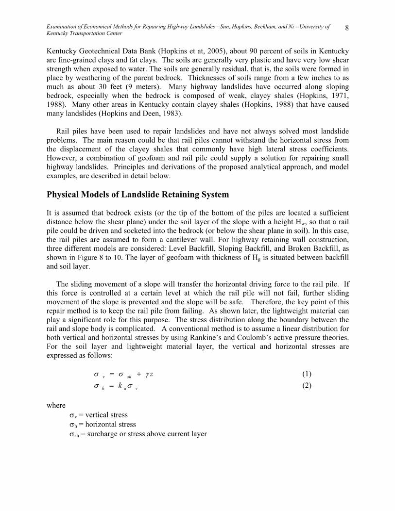
8
Kentucky Geotechnical Data Bank (Hopkins et at, 2005), about 90 percent of soils in Kentucky are fine-grained clays and fat clays. The soils are generally very plastic and have very low shear strength when exposed to water. The soils are generally residual, that is, the soils were formed in place by weathering of the parent bedrock. Thicknesses of soils range from a few inches to as much as about 30 feet (9 meters). Many highway landslides have occurred along sloping bedrock, especially when the bedrock is composed of weak, clayey shales (Hopkins, 1971, 1988). Many other areas in Kentucky contain clayey shales (Hopkins, 1988) that have caused many landslides (Hopkins and Deen, 1983). Rail piles have been used to repair landslides and have not always solved most landslide problems. The main reason could be that rail piles cannot withstand the horizontal stress from the displacement of the clayey shales that commonly have high lateral stress coefficients. However, a combination of geofoam and rail pile could supply a solution for repairing small highway landslides. Principles and derivations of the proposed analytical approach, and model examples, are described in detail below. Physical Models of Landslide Retaining System It is assumed that bedrock exists (or the tip of the bottom of the piles are located a sufficient distance below the shear plane) under the soil layer of the slope with a height Hw, so that a rail pile could be driven and socketed into the bedrock (or below the shear plane in soil). In this case, the rail piles are assumed to form a cantilever wall. For highway retaining wall construction, three different models are considered: Level Backfill, Sloping Backfill, and Broken Backfill, as shown in Figure 8 to 10. The layer of geofoam with thickness of Hg is situated between backfill and soil layer. The sliding movement of a slope will transfer the horizontal driving force to the rail pile. If this force is controlled at a certain level at which the rail pile will not fail, further sliding movement of the slope is prevented and the slope will be safe. Therefore, the key point of this repair method is to keep the rail pile from failing. As shown later, the lightweight material can play a significant role for this purpose. The stress distribution along the boundary between the rail and slope body is complicated. A conventional method is to assume a linear distribution for both vertical and horizontal stresses by using Rankine’s and Coulomb’s active pressure theories. For the soil layer and lightweight material layer, the vertical and horizontal stresses are expressed as follows: zshv γσσ += (1) vah k σσ = (2) where
σv = vertical stress σh = horizontal stress σsh = surcharge or stress above current layer

Examination of Economical Methods for Repairing Highway Landslides—Sun, Hopkins, Beckham, and Ni --University of Kentucky Transportation Center
9
Hg Hw
Bedrock
Geofoam layer
Level Backfill
Surcharge
Hb Backfill, γb
Soil layer, γs
Hg Hw
Bedrock
Geofoam layer
Level Backfill
Surcharge
Hb Backfill, γb
Soil layer, γs
Figure 8. Landslide retaining system model 1, Level Backfill
Hg Hw
Slope Angle α
Bedrock
Geofoam layer
Sloping Backfill
HbBackfill, γb
Soil layer, γs
Greater or Equal 2 * Hw
Hg Hw
Slope Angle α
Bedrock
Geofoam layer
Sloping Backfill
HbBackfill, γb
Soil layer, γs
Greater or Equal 2 * Hw
Figure 9. Landslide retaining system model 2, Sloping Backfill

Examination of Economical Methods for Repairing Highway Landslides—Sun, Hopkins, Beckham, and Ni --University of Kentucky Transportation Center
10
γ = unit weight of material contact to the rail pile z = depth from the surface ka = coefficient of active earth pressure
In model 1 (Level Backfill), ka can be expressed in the form
ϕϕ
sin1sin1
+−=ak (3)
In model 2 (Sloping Backfill), ka can be expressed in the form
ϕαα
ϕααα22
22
coscoscos
coscoscos2cos−+
−−=ak (4)
In model 3 (Broken Backslope), ka can be expressed in the form
2
2
cos)sin(sin1
cos
−⋅+
=β
βϕϕ
ϕak
(5)
Hg Hw
Slope Angle α
Bedrock
Soil layer,
Geofoam layer
Backfill,
Broken Backslopeβ
ht
= 2 * Hw
Hbγb
γs
Hg Hw
Slope Angle α
Bedrock
Soil layer,
Geofoam layer
Backfill,
Broken Backslopeβ
ht
= 2 * Hw
Hbγb
γs
Figure 10. Landslide retaining system model 3, Broken
Backslope

Examination of Economical Methods for Repairing Highway Landslides—Sun, Hopkins, Beckham, and Ni --University of Kentucky Transportation Center
11
Where, φ is the friction angle of soil or lightweight material. α is slope angle in model 2. β is thenominal slope of backfill behind wall and it can be calculated from
.2
tan 1
⋅−
= −
s
st
HHh
β (6)
The value of ka of the geofoam material is between 0.1 and 0.2 (defined from experiments). In this case it is not determined by Equations (3), (4), or (5). The bending moment of the rail mainly comes from the horizontal stress because vertical stress is parallel to the axis of the rail pile. The distribution of horizontal stresses along rail pile is shown on Figure 11.
As stated previously, the safety factor of the repaired landslide is determined by the rail pile status. The rail pile may fail in two situations. One case occurs when the bending stress is too large at fixed end. Another situation occurs when the deflection is too large at the free end. In the models shown in Figures 8 through 10, the allowed bending stress at the fixed end is always reached before the allowable deflection is reached at the free end if wall height is less than 31 ft. and allowable deflection is less than 4% of wall height Hw. Therefore, when height of retaining wall is less than 31 ft., safety factor is determined by the strength of the rail pile and the actual maximum bending stress at the fixed end of the rail pile. Safety factor is expressed as follows:
F a
m
=σσ
(7)
Hg Hw
Bedrock
Soil layer
Geofoam layer
Backfill
Rail Pile
Hg Hw
Bedrock
Soil layer
Geofoam layer
Backfill
Rail Pile
Figure 11. Distribution of the horizontal stress along the
rail pile

Examination of Economical Methods for Repairing Highway Landslides—Sun, Hopkins, Beckham, and Ni --University of Kentucky Transportation Center
12
where F is the safety factor, σa is the allowable strength of the rail pile and σm is the maximum bending stress at the fixed end of the pile. The σm is determined by
σm
mM yI
= (8)
where Mm is maximum bending moment at the fixed end of the pile, y is the distance between the edge of the rail pile and natural surface of the pile and I is the moment of inertia of the rail pile cross section. Then, the safety factor can be expressed as
F I
yMa
m
=σ
(9) σa , y and I are all constants for a given rail pile, or any other piles. Therefore remaining thing is to calculate the Mm. Moment, Mm, is calculated according to the horizontal stress along the rail pile. Distribution of horizontal stress along the rail consists of several segments. Each segment of horizontal stress will produce a bending moment, Mi, at the fixed end of the rail pile. Mi is calculated as follows: M P Hi i i= (10)
where, Pi is the resultant force of the horizontal stress of the segment and Hi is the distance between the acting point of resultant force and fixed end of the rail pile, as shown in Figure 12. Pi and Hi are obtained by P H H Si i i i i r= − +0 5 1 2 1 2. ( )( )σ σ (11) and
H H H H
i ii i i i
i i
= +− +
+21 2 2 1
1 2
23
( )( )( )
σ σσ σ (12)
respectively. Sr in Equation 11 is the spacing of the rail pile. The total moment Mm is obtained by
M Mm i
i
N
==∑
1 (13)

Examination of Economical Methods for Repairing Highway Landslides—Sun, Hopkins, Beckham, and Ni --University of Kentucky Transportation Center
13
where N is the number of the segment of horizontal stress distribution along the rail. N is not necessary equal to the number of layers of material in the slope. When a different thickness of geofoam is used, the force distribution on the rail pile will vary. Consequently, the safety factor for landslide retaining wall system will be different. By using equations (7) through (13) and different thickness of geofoam, a curve of safety factor as a function of geofoam thickness will be obtained. From this relationship, the thickness of geofoam (or other lightweight material) for a selected factor of safety may be determined to maintain a stable and safe landslide retaining wall system. When the factor of safety is selected the thickness of lightweight is established. Implementation Under GUI Environment As a tool, the friendly Graphical User Interface (GUI) constructed for a program is one of the most important targets. Using PowerBuilder over Windows platform, the theory presented above is built into an event-driven program. When this program is started, the first interface shown on the computer screen is a data entry sheet with default design data, geometry of the landslide retaining wall system, and an analyzing curve of safety factor versus geofoam thickness, as shown in Figure 13. If any datum is changed, a new analyzing curve is drawn on the screen. Moving the mouse to a point on the analyzing curve, the user can see a value of safety factor and a corresponding thickness of lightweight material, as shown in Figure 14. By clicking a point on the analyzing curve, a detail design sheet, connected with data on the clicked point, will appear as illustrated in Figure 15. On this design sheet, all data entry parameters used in analyzing a problem are automatically listed. A drawing with the landslide retaining wall system selected by the user is displayed. As shown in Figure 15, the Organization, Designer’s name, Design Date, and project Location are entered. After that information is added, the sheet is ready to print for a user’s report.
σi1
σi2
Pi
HiHi2
Layer i
Hi1
Hw
Bedrock
Rail Pile
σi1
σi2
Pi
HiHi2
Layer i
Hi1
Hw
Bedrock
Rail Pile
Figure 12. Resultant force of the horizontal stress for one
typical segment on the rail pile

Examination of Economical Methods for Repairing Highway Landslides—Sun, Hopkins, Beckham, and Ni --University of Kentucky Transportation Center
14
If the retaining wall model is changed, a new screen with the new model appears, as shown in Figure 16. On the page layout, the drawing with landslide retaining wall system illustrates every parameter describing the system. A set of default parameters is ready for general use. Parameters can be modified based on the user’s requirement. After clicking the OK button, the relationship of safety factor as a function of thickness of geofoam (or other lightweight material) involving new parameters is displayed. When the user changes to different lightweight material, a new screen with some default data, as shown in Figure 17, will appear. The default data can be changed to suit any practical project. After clicking on OK, new analyzing curve will be related to new lightweight material. Two types of rail piles, 136/140 lbs/Yd and 130/133 lbs/Yd, are built in as default rail piles. If the user has a different pile to analyze, “Other Rail” in the Rail Pile Type dropdown list is an option. When this option is used a new rail property screen with some default data, as shown in Figure 18, will appear for the user to enter new parameters. The user can modify data on screen to match a real problem. After clicking on OK, a new analyzing curve will be associated with the new pile.
Figure 13. Friendly interface for landslide retaining wall analysis

Examination of Economical Methods for Repairing Highway Landslides—Sun, Hopkins, Beckham, and Ni --University of Kentucky Transportation Center
15
There are three different landslide retaining wall models built into this application. They are Level Backfill, Sloping Backfill, and Broken Backslope. When any model is selected, the corresponding coefficient of active earth pressure, ka, will be calculated automatically using one of equations (3), (4) or (5). Other data including rail pile spacing, properties of backfill, lightweight material, and soil can be changed directly on screen. A new analyzing curve will be created on the screen instantly after any datum has been modified. Comparing with CTBRAIL Rail Design Program Developed by KyTC One of the ways this Windows program can be checked is comparing results with an existing program. Program CTBRAIL provides designs for three models of Level Backfill, Sloping Backfill, and Broken Backslope. But, it does not have multiple layer design capability. Comparison of safety factors obtained by programs developed by Kentucky Transportation Cabinet (KyTC) and UKTC is only based on one single layer situation, shown in Table 1.
Figure 14. Detail information shows up by moving mouse to one point

Examination of Economical Methods for Repairing Highway Landslides—Sun, Hopkins, Beckham, and Ni --University of Kentucky Transportation Center
16
Figure 15. A detail design sheet shows up by clicking a point on analyzing curve
Figure 16. Data input sheet for corresponding retaining model

Examination of Economical Methods for Repairing Highway Landslides—Sun, Hopkins, Beckham, and Ni --University of Kentucky Transportation Center
17
From Table 1, results obtained from two different programs for models of Level Backfill and Sloping Backfill are identical. There are some differences in the two programs. For the Broken Backslope, the UKTC program yields factors of safety that range 4 to 7.6 percent lower than factors of safety obtained from the KyTC program. The higher the retaining wall, the smaller the difference between these two programs. Factors of safety obtained from the UKTC program are more conservative than the factors of safety calculated by the KyTC program.
Figure 17. Property input sheet for selected lightweight materials
Figure 18. Data input sheet for selected rail pile

Examination of Economical Methods for Repairing Highway Landslides—Sun, Hopkins, Beckham, and Ni --University of Kentucky Transportation Center
18
Examples: Analyzing Retaining Wall with different Lightweight Materials Example 1. Given geometry of retaining wall and properties of backfill and soil are as follows:
Surcharge: 250 lb/ft2 Depth to Bedrock (Retaining Wall Height): 18 ft. Depth to Water Table: 18 ft. Thickness of Backfill: 2 ft. Unit weight of Backfill: 125 lb/ft3 Friction Angle of Backfill: 25 Unit weight of Soil Layer: 125 lb/ft3 Friction Angle of Soil Layer: 25 Rail Pile: 136/140 lbs/Yd Rail Spacing: 2 ft.
Assuming design target for safety factor as 1.4, the results listed in Table 2 for different lightweight materials show different thickness corresponding to different materials. The results indicate that unit weight of material plays a considerable role in the level of stability for the retaining system. The heavier material requires a larger thickness of backfill material than lighter backfill materials. As shown by the results in Table 2, geofoam requires less thickness (and excavation at old sites) and it is the best candidate for landslide retaining wall system due to its lightest unit weight. Example 2. All conditions are the same as those in example 1. However, a water table with a height of 10 feet is added for this example. Assuming a design target for the safety factor as 1.4, calculated results and the conditions of example 1, are listed in Table 3 for different lightweight materials. Comparing the results of
Table 1.
Comparison of Safety Factors Between Progrms Developed by KyTC and UKTC
Surcharge: 250 lb/ft2, Unit weight of Soil Layer: 125 lb/ft3, Friction Angle of Soil Layer: 25, Rail Pile: 136/140 lbs/Yd, Rail Spacing: 2 ft. Wall Height (ft.) 10 15 20
KyTC Program 5.20 1.76 0.80 Level Backfill UKTC Program 5.20 1.76 0.80 KyTC Program 3.49 1.18 0.54 Sloping Backfill UKTC Program 3.49 1.18 0.54 KyTC Program 4.81 1.70 0.78 UKTC Program 4.47 1.60 0.75 M
odel
Broken Backslope Difference (%) 7.61 6.25 4.00

Examination of Economical Methods for Repairing Highway Landslides—Sun, Hopkins, Beckham, and Ni --University of Kentucky Transportation Center
19
Example 1 to those of Example 2, the required thickness of the lightweight material increases with the introduction of a ten-foot high water table into the problem.
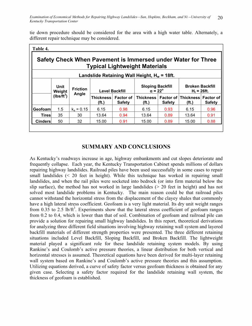
Example 3. Safety check for immersed case. All conditions are the same as those in example 1, except the water table is located at the pavement surface. For this immersed case and assuming different lightweight materials, the factors of safety are not greater than 1.0, as shown Table 4. That means, in an immersed situation, even lightweight material cannot provide a safe design. As shown in Table 4, no thickness of lightweight material can reach the maximum allowed thickness of, 16 feet in this particular example. Thicknesses in the Table 4 show maximum thicknesses can be used without any buoyant force. If thickness is greater than thickness indicated in the Table 4, buoyant force will damage pavement. Therefore a
Table 2.
Comparison of Thickness between Different Lightweight Materials with Safety Factor ≈ 1.4,
Without Water Table Landslide Retaining Wall Height, Hw = 18ft.
Thickness Required (ft.)
Unit Weight (lbs/ft3)
Friction Angle
Level Backfill
Sloping Backfill, α = 22o
Broken Backfill, Ht
= 26ft. Geofoam 1.5 ka = 0.15 2.00 4.75 3.25
Tires 35 30 3.50 9.25 6.40 Cinders 50 32 4.00 8.50 7.00
Table 3.
Comparison of Thickness between Different Lightweight Materials with Safety Factor ≈ 1.4,
With Water Table Landslide Retaining Wall Height, Hw = 18ft.
Depth to Water Table = 10ft. Thickness Required (ft.)
Unit Weight (lbs/ft3)
Friction Angle
Level Backfill
Sloping Backfill, α = 22o
Broken Backfill, Ht
= 26ft. Geofoam 1.5 ka = 0.15 2.50 5.00 3.75
Tires 35 30 4.50 10.50 7.50 Cinders 50 32 5.00 9.00 8.50
Examination of Economical Methods for Repairing Highway Landslides—Sun, Hopkins, Beckham, and Ni --University of Kentucky Transportation Center
20
tie down procedure should be considered for the area with a high water table. Alternately, a different repair technique may be considered.
SUMMARY AND CONCLUSIONS As Kentucky’s roadways increase in age, highway embankments and cut slopes deteriorate and frequently collapse. Each year, the Kentucky Transportation Cabinet spends millions of dollars repairing highway landslides. Railroad piles have been used successfully in some cases to repair small landslides (< 20 feet in height). While this technique has worked in repairing small landslides, and when the rail piles were socketed into bedrock (or into firm material below the slip surface), the method has not worked in large landslides (> 20 feet in height) and has not solved most landslide problems in Kentucky. The main reason could be that railroad piles cannot withstand the horizontal stress from the displacement of the clayey shales that commonly have a high lateral stress coefficient. Geofoam is a very light material. Its dry unit weight ranges from 0.35 to 2.5 lb/ft3. Experiments show that the lateral stress coefficient of geofoam ranges from 0.2 to 0.4, which is lower than that of soil. Combination of geofoam and railroad pile can provide a solution for repairing small highway landslides. In this report, theoretical derivations for analyzing three different field situations involving highway retaining wall system and layered backfill materials of different strength properties were presented. The three different retaining situations included Level Backfill, Sloping Backfill, and Broken Backfill. The lightweight material played a significant role for these landslide retaining system models. By using Rankine’s and Coulomb’s active pressure theories, a linear distribution for both vertical and horizontal stresses is assumed. Theoretical equations have been derived for multi-layer retaining wall system based on Rankine’s and Coulomb’s active pressure theories and this assumption. Utilizing equations derived, a curve of safety factor versus geofoam thickness is obtained for any given case. Selecting a safety factor required for the landslide retaining wall system, the thickness of geofoam is established.
Table 4.
Safety Check When Pavement is Immersed under Water for Three Typical Lightweight Materials
Landslide Retaining Wall Height, Hw = 18ft.
Level Backfill Sloping Backfill
α = 22o Broken Backfill
Ht = 26ft.
Unit Weight (lbs/ft3)
Friction Angle
Thickness (ft.)
Factor of Safety
Thickness (ft.)
Factor of Safety
Thickness (ft.)
Factor of Safety
Geofoam 1.5 ka = 0.15 6.15 0.98 6.15 0.93 6.15 0.96 Tires 35 30 13.64 0.94 13.64 0.89 13.64 0.91
Cinders 50 32 15.00 0.91 15.00 0.89 15.00 0.88

Examination of Economical Methods for Repairing Highway Landslides—Sun, Hopkins, Beckham, and Ni --University of Kentucky Transportation Center
21
Using PowerBuilder software over Windows platform, the theory presented above is built into an event-driven program with friendly Graphical User Interface (GUI). Comparison of Safety Factors obtained by programs developed by KyTC and based on this theory has shown identical results for models of Level Backfill and Sloping Backfill. For the Broken Backslope situation, however, some small differences occur in the results obtained from the two programs. Results obtained for Broken Backslope from the UKTC program range from about 4.0 to 7.6 percent lower than results obtained from the KyTC program. As the height of retaining wall increase, the differences in the two programs decrease. Results obtained by the program described herein and based on theoretical analysis is more conservative than results obtained by the KyTC program for the Broken Backslope model. The results of examples in this report indicate that unit weight of material play a considerable role for retaining system. A larger thickness of lightweight material is required as the unit weight of the lightweight material increases. Geofoam is the best candidate for landslide retaining wall system due to its ultra light unit weight. Also, the program developed in this report can predict maximum thicknesses of lightweight material without any buoyant force. If thickness is greater than the maximum thickness predicted, then the pavement will be damaged by the buoyant force. Therefore a tie-down procedure should be considered for an area with a high water table. The program developed in this report is an only program analyzing a multi-layer landslide retaining wall system. Actual job sites are needed to verify this theoretical approach.

Examination of Economical Methods for Repairing Highway Landslides—Sun, Hopkins, Beckham, and Ni --University of Kentucky Transportation Center
22
REFERENCES Braja M. Das; (1990) “Principles of Geotechnical Engineering,” Second Edition, PWS-KENT
Publishing Company. Girdler, H.F. and Hopkins, T.C.; (1973) “Stability Analysis of Slide at M.P. 152.7", Research
Report no. 372, Division of Research, Kentucky Department of Highways. Hopkins, T. C.; (1971) “Investigation of a Side-Hill Embankment Slope Failure on I 64, Bath
County, Milepost 118,” Division of Research, Kentucky Department of Transportation. Hopkins, T. C.; (July 1972) “Unstable Embankment, US 119," Research Report 334, Division of
Research, Kentucky Department of Highways. Hopkins, T. C. ; (1973) “ Settlement of Highway Bridge Approaches and Embankment
Foundations, Bluegrass Parkway Bridges over Chaplin River,” Research Report 363, Division of Research, Kentucky Department of Highways
Hopkins, T. C.; (1973) “Failure of the Southern Approach Embankment of the Bridge across the Licking River, US 68, Lexington to Maysville Road,” Memorandum report, Division of Research, Kentucky Department of Highways.
Hopkins, T. C. and Yodel, S.M.; (1973), “ ‘Remedial Stability Analysis of Unstable, Eastern Approach Embankment, Bluegrass Parkway Bridges Over Chaplin River,” Report Number 370, Kentucky Department of Highways.
Hopkins, T. C. ; (February 1973) “Stability of a Side-Hill Embankment, I 64 Lexington-Catlettsburg Road,” Research Report 363, Division of Research, Kentucky Department of Transportation.
Hopkins, T. C. and Deen, R.C.; (March-December 1983) "Identification of Kentucky Shales," Geotechnical Testing Journal, Vol. 7, American Society for Testing Materials, March-December 1983.
Hopkins, T. C.; Allen, D.L.; and Hughes, R.D.; (July 1983) "Geotechnical, Hydrologic, and Hydraulic Investigation of Mill Creek Dam -- Phase II," Kentucky Transportation Research Program, University of Kentucky, UKTRP 83-14, July 1983.
Hopkins, T. C., (April 1985) "Long-Term Movements of Highway Bridge Approach Embankments and Pavements," Research Report UKTRP 85-12, University of Kentucky Transportation, April 1985.
Hopkins, T. C., (January 1988) "Shear Strength of Compacted Shales," University of Kentucky Transportation Center, College of Engineering, Research Report UKTRP 88-1, January 1988.
Hopkins, T. C. and Deen, R.C.; (March-December 1983) “Identification of Shales,” Geotechnical Testing Journal, Vol. 7, American Society for Testing Materials.
Hopkins, T. C.; (April 1985) “Long-Term Movements of Highways Bridge Approach Embankments and Pavements,” Research Report UKTRP 85-12, University of Kentucky Transportation Center.
Hopkins, T. C. and Gilpin, B. C.; (August, 1981) “Identification of Kentucky Shales,” University of Kentucky Transportation Program, Research Report UKTRP-81-16.
Hopkins, T. C.; Allen, D.L.; Deen, R. C.; and Grayson, C. G.; (December 1988) “Slope Maintenance and Slide Restoration,” Report FHWA-RT-88-040, Kentucky Transportation Center, College of Engineering, Lexington, Kentucky (This one-day course was developed for the Federal Highway Administration and has been taught throughout the country and South America).
Examination of Economical Methods for Repairing Highway Landslides—Sun, Hopkins, Beckham, and Ni --University of Kentucky Transportation Center
23
Hopkins, T. C.; Beckham, T. L.; Sun, C.; and Pfalzer, B.; (March 2005) “Kentucky Geotechnical Database,” Report KTC-05-03/SPR227-01-1F, Kentucky Transportation Center, College of Engineering, Lexington, Kentucky.
Karl Terzaghi; (1943) “Theoretical Soil Mechanics,” John Wiley and Sons, Inc. Mathis, H. and Monroe, J.; (October 1995) “Private Communication,” Geotechnical Branch of
the Division of Materials, Kentucky Transportation Cabinet. Mathis, H. And Monroe, J.; (1994) “Perry County Landslide Correction , KY 28, MP 4.75,”
Report Number L-3-94) Mathis, H. And Monroe, J.; (1994) “Estill County Landslide Correction, KY 1571, MP 1.2,”
Report Number L-10-94. Mathis, H. And Monroe, J.; (1994) “Henry County Landslide Correction, KY 389 , MP 13.4,”
Report Number L-16-94). Mathis, H. And Shyrock, R.; (1990) “City of Covington Landslide Correction, KY 8,” Report
Number L-10-90). Mathis, H. And Shyrock, R.; (1991) “Leslie County Landslide Correction, KY 118,” Report
Number L-15-91). Negussey, D. and Sun M., (1996) "Reducing Lateral Pressure by geofoam (EPS) Substitution."
Proceedings of the International Symposium on EPS Construction Method, Tokyo, Japan, 1996.
Negussey, D., (1997) “Properties & Applications of Geofoam,” Society of the Plastics Industry, Inc.
Ronald F. Scott; (1963) “Principles of Soil Mechanics,” Addison-Wesley Publishing Company, Inc.