research rrecord - nh.gov - the official web site of … rumbles immediately reflected through the...
TRANSCRIPT

FFiinnaall RReeppoorrtt
Prepared by the New Hampshire Department of Transportation in Cooperation with the U.S. Department of Transportation, Federal Highway Administration
PPrreeppaarraattiioonn ooff RRuummbbllee SSttrriippss PPrriioorr ttoo OOvveerrllaayymmeenntt
RRee sseeaarrcc hh RR eecc oo rrdd


Technical Report Documentation Page
1. Report No. FHWA-NH-RD-13733V
2. Gov. Accession No.
3. Recipient's Catalog No.
4. Title and Subtitle
PREPARATION OF RUMBLE STRIPS PRIOR TO OVERLAYMENT
5. Report Date
July 2010
6. Performing Organization Code
7. Author(s) Denis M. Boisvert, P.E., NHDOT Chief of Materials Technology
8. Performing Organization Report No.
9. Performing Organization Name and Address
Bureau of Materials & Research New Hampshire Department of Transportation PO Box 483, 5 Hazen Drive Concord, NH 03302-0483
10. Work Unit No. (TRAIS)
11. Contract or Grant No. 13733V, X-A000(385)
12. Sponsoring Agency Name and Address
New Hampshire Department of Transportation PO Box 483, 5 Hazen Drive Concord, NH 03302-0483
13. Type of Report and Period Covered FINAL REPORT
14. Sponsoring Agency Code
15. Supplementary Notes In cooperation with the U. S. Department of Transportation, Federal Highway Administration
16. Abstract The use of rumble strips in pavement to reduce run-off-road accidents is relatively new. In New Hampshire, these installations began in the mid to late 1990s. The New Hampshire Department of Transportation performed its first overlay of rumble strips in Nashua on its Central Turnpike during the 2003 construction season. The rumbles immediately reflected through the one-inch overlay, raising concerns over whether these features should receive special preparation.
A national materials list-serve was used to solicit the practices of other state and provincial agencies. Eighteen respondents indicated a range of opinion from grinding the strip and shimming before paving, to doing nothing provided the strip is less than a ½-inch deep and the overlay is more than 4 inches. The opinions appeared to be based on general paving experience rather than knowledge about this specific condition. An additional 17 respondents either had no opinion, or did not install rumble strips. We concluded that there was no conventional method for overlaying rumble strips.
This research project was launched with the objective of developing appropriate techniques, sequences and/or options to perform the preparation and overlay operation successfully and economically. Rumble strip pavement performance within the study area demonstrated that the simplest and least costly method produced a durable pavement and replacement rumble strip, but other problems related to thin lift overlays during subsequent paving seasons eventually lead to a specification requiring the preparation treatment needing the greatest effort.
For the 2010 season, NHDOT elected to require that all rumbles be milled and inlayed prior to placement of the overlay. The inlay technique has been successfully used without overlay for removal of rumble strips to create temporary traffic detours. At the time of this report, contractors have developed the tools and techniques needed to install the 20-inch wide inlay with reasonable efficiency, such that it is not the laborious, hand-work operation that it was during the test site construction in 2005. A new bid item has been added to the construction contracts that provide for an intermediate bid price that is neither full-lane machine method, nor high cost handwork. The item includes the rumble milling and replacement inlay.
17. Key Words
Hot mix asphalt, Asphalt pavements, Milling, Rumble strip, Bituminous overlay, Surface preparation
18. Distribution Statement
No restrictions. This document is available to the public through the National Technical Information Service, Springfield, Virginia, 22161
19. Security Classif. (of this report)
Unclassified
20. Security Classif. (of this page)
Unclassified
21. No. of Pages
17
22. Price

DISCLAIMER
This document is disseminated under the sponsorship of the New Hampshire Department of Transportation (NHDOT) and the U.S. Department of Transportation Federal Highway Administration (FHWA) in the interest of information exchange. The NHDOT and FHWA assume no liability for the use of information contained in this report. The document does not constitute a standard, specification, or regulation. The NHDOT and FHWA do not endorse products, manufacturers, engineering firms, or software. Products, manufacturers, engineering firms, software, or proprietary trade names appearing in this report are included only because they are considered essential to the objectives of the document.
ACKNOWLEDGEMENTS
The Bureau would like to thank the staff of NHDOT Highway Design and Construction Bureaus for their participation in the administration of this project. The Bureau would also like to thank its Geotechnical Section for its assistance in retrieving core samples and the Materials Technology Section for laboratory testing of those cores.
Project Sponsor: Craig Green, NHDOT Highway Design Bureau Administrator
Technical Advisory Group:
Frank Bauer, NHDOT Construction Bureau
Scott Carlson, NHDOT Construction Bureau
Michael Fudala, NHDOT Highway Design Bureau
Michael O’Malley, NHDOT Turnpikes Bureau
Wayne Roswell, NHDOT Highway Maintenance Bureau
Jamie Sikora, FHWA, NH Division
TAG Coordinator: Denis Boisvert, NHDOT Materials & Research Bureau

Report No. FHWA-NH-RD-13733V
PREPARATION OF RUMBLE STRIPS PRIOR TO OVERLAYMENT
Prepared By: Denis M. Boisvert, P.E.
Chief of Materials Technology
NEW HAMPSHIRE DEPARTMENT OF TRANSPORTATION BUREAU OF MATERIALS & RESEARCH
P.O. Box 483 Concord, NH 03302-0483
Phone (603) 271-3151 Fax (603) 271-8700
July 21, 2010


TABLE OF CONTENTS EXECUTIVE SUMMARY ........................................................................................................................................... 1 EXISTING CONDITIONS ........................................................................................................................................... 1 TEST SITES .................................................................................................................................................................. 1 EARLY OBSERVATIONS........................................................................................................................................... 2 SUBSEQUENT OBSERVATIONS .............................................................................................................................. 4 DENSITY ANALYSIS ................................................................................................................................................. 5 EVALUATIONS ........................................................................................................................................................... 6 RECOMMENDATIONS ............................................................................................................................................... 6 IMPLEMENTATION ................................................................................................................................................... 7
APPENDIX – RUMBLE STRIP STANDARD DETAIL


1
EXECUTIVE SUMMARY
The use of rumble strips in pavement to reduce run-off-road accidents is relatively new. In New Hampshire, these installations began in the mid to late 1990s. The New Hampshire Department of Transportation performed its first overlay of rumble strips in Nashua on its Central Turnpike during the 2003 construction season. The rumbles immediately reflected through the one-inch overlay, raising concerns over whether these features should receive special preparation. A national materials list-serve was used to solicit the practices of other state and provincial agencies. Eighteen respondents indicated a range of opinion from grinding the strip and shimming before paving, to doing nothing provided the strip is less than a ½-inch deep and the overlay is more than 4 inches. The opinions appeared to be based on general paving experience rather than knowledge about this specific condition. An additional 17 respondents either had no opinion, or did not install rumble strips. We concluded that there was no conventional method for overlaying rumble strips. This research project was launched with the objective of developing appropriate techniques, sequences and/or options to perform the preparation and overlay operation successfully and economically. Rumble strip pavement performance within the study area demonstrated that the simplest and least costly method produced a durable pavement and replacement rumble strip, but other problems related to thin lift overlays during subsequent paving seasons eventually lead to a specification requiring the preparation treatment needing the greatest effort. For the 2010 season, NHDOT elected to require that all rumbles be milled and inlayed prior to placement of the overlay. The inlay technique has been successfully used without overlay for removal of rumble strips to create temporary traffic detours. At the time of this report, contractors have developed the tools and techniques needed to install the 20-inch wide inlay with reasonable efficiency, such that it is not the laborious, hand-work operation that it was during the test site construction in 2005. A new bid item has been added to construction contracts that provide for an intermediate bid price that is neither full-lane machine method, nor high cost handwork. The item includes the rumble milling and replacement inlay.
EXISTING CONDITIONS
New Hampshire constructs its rumble strips by milling 3/8 inch to 5/8 inch deep by 12 to 16 inches wide depressions into the wearing course of bituminous pavements. The milled areas are located approximately two feet away from the lane line, a location preferred by the Highway Maintenance Bureau to keep them out of the wheel path of the snow plowing trucks.
TEST SITES
Four rumble strip preparation test scenarios were developed for trial within a paving project scheduled for 2005. A 2,000-foot segment of the northbound lane of I-89 in Lebanon, NH was designated for preparation of the 500-foot test areas, followed by placement of a 1.5-inch overlay. The preparation scenarios were completed on the night of June 30/July 1, 2005 and are summarized as follows:

2
Test Section A: Tack-Shim-Overlay
1. Tack the entire 10-foot shoulder width 2. Place ½-inch leveling shim and compact with 10-ton roller 3. Place 1 ½-inch overlay and compact with 10 ton and 30 ton rollers
Test Section B: Tack-Overlay
1. No special treatment for rumble strip 2. Tack the entire 10-foot shoulder width 3. Place 1 ½-inch overlay and compact with 10 ton and 30 ton rollers
Test Section C: Mill-Inlay-Overlay
1. Mill out 20-in. wide rumble strip with cold-planing trimmer, ½-inch deep 2. Tack milled-out rumble strip 3. Use a Bobcat-mounted jig to inlay the milled rumble strip 4. Compact inlay with a 10-ton roller 5. Tack over inlay and entire shoulder 6. Place 1.5-inch overlay, and compact with 10 ton and 30 ton rollers
Test Section D: Mill-Overlay
1. Mill out 20-in. wide rumble strip with cold-planing trimmer, ½-inch deep 2. Tack entire shoulder 3. Place 1.5-inch overlay, and compact with 10 ton and 30 ton rollers.
EARLY OBSERVATIONS
The test sites were observed on July 5, 2005 to record their short-term conditions following construction. Section A (tack, shim and overlay) showed no indication of rumble strip reflection. Section B (tack and overlay) showed occasional longitudinal cracks along the edge of the rumble strip (Figure 1), indicating movement of the mix by the roller through the affected rumble. An expanded discussion of this condition can be found in the Implementation section later in this report. The rumble strip had reflected through the overlay along the entire length of this section (Figure 2). Additionally, a parallel line of “reflected” rumbles was observed in this section (Figure 3). The prevailing theory is that the vibratory roller drum bounces and/or teeters due to the alternating mix thickness/stiffness in the rumble strip, causing the drum to form an indentation of the surface alongside the original rumble strip.

3
Section C (mill, inlay and overlay) and Section D (mill and overlay) showed no reflection of the longitudinal milling of the rumble strip, which would have displayed as a rut. A shadow was the only evidence of the former safety feature.
Figure 1 – Cracks along edge of former Rumbles (Section B)
Figure 2 – Reflected Rumble (Section B)
Reflection of Original Rumble Parallel Reflection
Figure 1 – Parallel “Reflection” (Section B)
Sect. C
Sect. D
Figure 2 – Shadowing (Sections C and D)

4
Occasional lateral cracks were observed in the shoulder of all Sections. These are common in overlay projects, and are not associated with the rumble strip overlay. Crack seal material in the existing pavement is heated by the new overlay mix, expands, and cracks the overlay pavement before it cools, causing an immediate defect.
SUBSEQUENT OBSERVATIONS
Two additional site visits followed to document the performance of each preparation scenario. The first was on April 27, 2006, following the first winter in service. A summary of observations follows: Section A (tack, shim and overlay) Mild depressions were now visible (Figure 5), presumably due to additional compaction of the “grader shim”. The bars could now be felt when driven upon. No structural distress was otherwise noted. Arrows in the photo below indicate dips in surface.
Section B (tack and overlay) continued to show a pronounced rumble strip reflection, visually enhanced by the abrasion of the rumble bars from snow plowing, as shown at right. This preparation method required the least effort, but resulted in poor aesthetics. No additional deterioration was noted, and pavement performance was satisfactory.
Section C (mill, inlay and overlay), which required the greatest number of steps to accomplish, still showed no reflection of the milled area, which would have displayed as a rut. Left, the outline of the former rumble strip was vaguely visible on the shoulder surface.
Straight Edge
Figure 3 – Depressions observed in Section A
Figure 4 – Reflection and Abrasion (Section B)
Figure 5 – Section C

5
Section D (mill and overlay), right, also showed no sign of reflection in the area of the former rumble strip, although discoloration (shadowing) was still evident.
The final site visit was made on June 8, 2007. The 2007 inspection showed no deterioration in any section since the previous year. New rumble strips were subsequently milled into the test areas as part of a statewide rumble installation project.
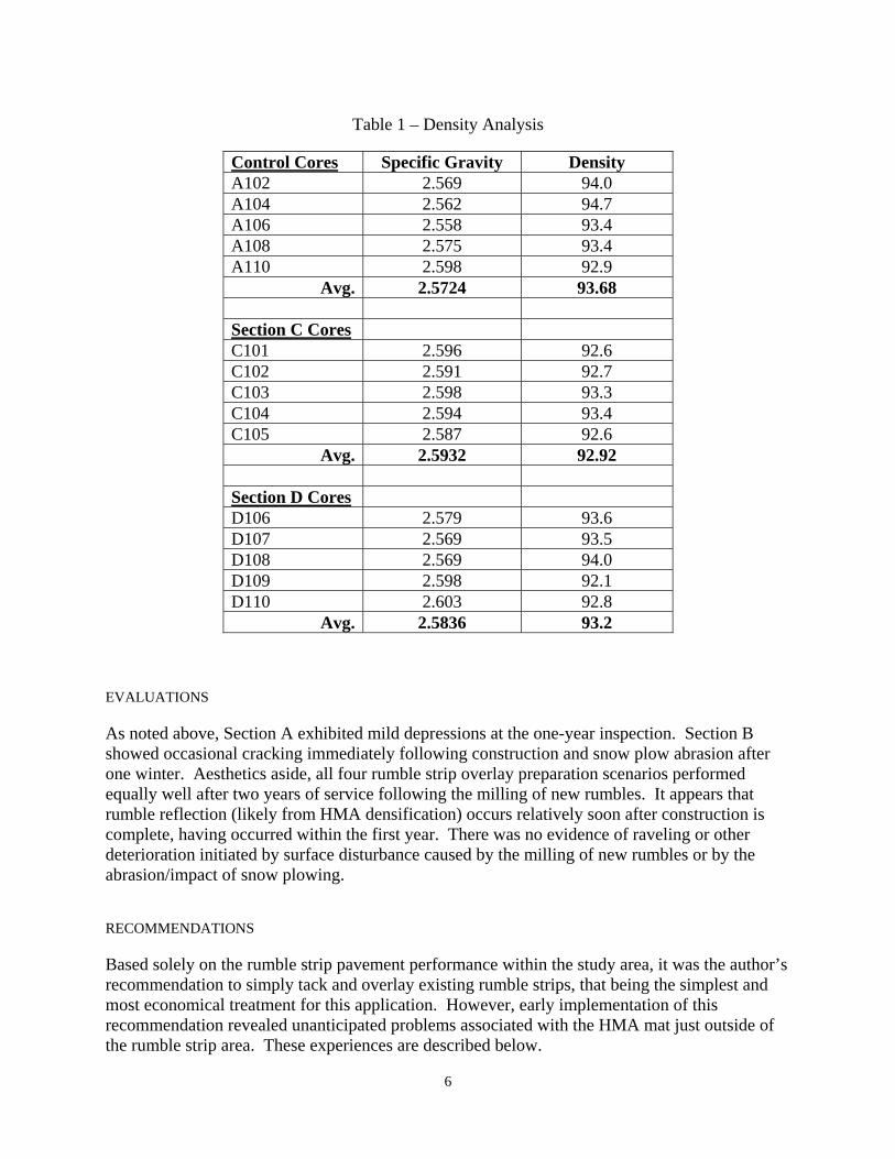
DENSITY ANALYSIS
One concern for durability was the potential decrease in compaction, caused by the differing overlay thicknesses placed over both the existing rumbles and the area of removed rumbles. Section D, for example, placed two inches of compacted mix in the rumble strip area, compared to the 1.5-inch overlay placed on the rest of the roadway. In addition to the 33% thicker lift placed in the rumble strip area, it was felt that the roller drum would bridge over the milled areas, achieving a reduced compactive effort in that area. Five cores were collected from the former rumble strip in Sections C and D to compare the overlay densities with the overlay from five cores collected in typical shoulder areas. Sections A and B were not sampled. The shape and size of the original remaining rumbles would prove too difficult to measure separately from the overlay material. The following table shows the Specific Gravity of each core and its density relative to the Rice Specific Gravity (Gmm). On average, the Section C cores (inlay and overlay) were found to have a density 0.76% lower than the control. While Section D cores (mill and overlay) had a density of only 0.48% lower than the control, showing that the lift thickness and bridging concerns were unfounded.
Figure 6 – Section D
Straight Edge
6
Table 1 – Density Analysis
Control Cores Specific Gravity Density A102 2.569 94.0 A104 2.562 94.7 A106 2.558 93.4 A108 2.575 93.4 A110 2.598 92.9
Avg. 2.5724 93.68 Section C Cores C101 2.596 92.6 C102 2.591 92.7 C103 2.598 93.3 C104 2.594 93.4 C105 2.587 92.6
Avg. 2.5932 92.92
Section D Cores D106 2.579 93.6 D107 2.569 93.5 D108 2.569 94.0 D109 2.598 92.1 D110 2.603 92.8
Avg. 2.5836 93.2
EVALUATIONS
As noted above, Section A exhibited mild depressions at the one-year inspection. Section B showed occasional cracking immediately following construction and snow plow abrasion after one winter. Aesthetics aside, all four rumble strip overlay preparation scenarios performed equally well after two years of service following the milling of new rumbles. It appears that rumble reflection (likely from HMA densification) occurs relatively soon after construction is complete, having occurred within the first year. There was no evidence of raveling or other deterioration initiated by surface disturbance caused by the milling of new rumbles or by the abrasion/impact of snow plowing.
RECOMMENDATIONS
Based solely on the rumble strip pavement performance within the study area, it was the author’s recommendation to simply tack and overlay existing rumble strips, that being the simplest and most economical treatment for this application. However, early implementation of this recommendation revealed unanticipated problems associated with the HMA mat just outside of the rumble strip area. These experiences are described below.

7
IMPLEMENTATION
Beginning in the 2007 paving season, NHDOT experienced some problems with overlaying rumble strips, in spite of the success of the test areas. This section describes the adjustments made to address these problems, and the evolution of NHDOT’s specification for this construction element.
1. In 2007, a 1.5” overlay project on I-89 suffered problems with achieving compaction in the rumble area. The contractor was forced to choose between compacting the 50-gyration Superpave mix until cracks appeared along the rumble strip or accepting the pay factor penalty for not meeting density requirements. Small longitudinal tears in the mix, located on the outside edge of the rumble were also observed, similar to the early cracks observed in test Section B above. It was felt that the existing rumble bars might have been the problem, causing the mix to "lock up" within the rumble, while the mix on the shoulder mat was free to move during compaction. The Department decided that it would then mill all rumbles, followed by overlay without an inlay, expecting to resolve the problem. The change was successful on subsequent I-89 projects.
2. The 2008 construction season included projects on I-93 and NH Route 101. Traffic levels on these highways required the use of 75-gyration mixes for the 1.5” overlays. The mill-and-overlay method was applied to these projects. During compaction, quarter-inch wide, longitudinal cracks up to 35' in length appeared on the outside edge of rumbles. The worst cracking appeared in superelevated curves. The mix surface was shiny along the edges of the removed rumble strip. "Overcompaction" issues were again suspected. The notch created by the removed rumble was also thought to restrict the lateral movement of the mix during breakdown rolling, resulting in the tear in the mat. One of the contractors (who had done the previous season’s I-89 work, and so, had the most experience with the problem) tried increasing the asphalt content, effectively making this same mix a 50-gyration mix. This change virtually eliminated the cracking.
3. The Department remained doubtful that the observed phenomenon was fully
understood. For the 2010 season, it has elected to require that all rumbles be milled and inlayed prior to placement of the overlay. The inlay technique has been successfully used without overlay for removal of rumble strips to create temporary traffic detours.
At this point in time, the contractors have developed the tools and techniques needed to install the 20-inch wide inlay with reasonable efficiency, such that it is not the laborious, hand-work operation that it was during the test site construction in 2005. A new bid item has been added to the construction contracts providing for an intermediate bid price that is neither full-lane machine method, nor high cost handwork. The item includes the rumble milling and replacement inlay, and is paid by the lineal foot.


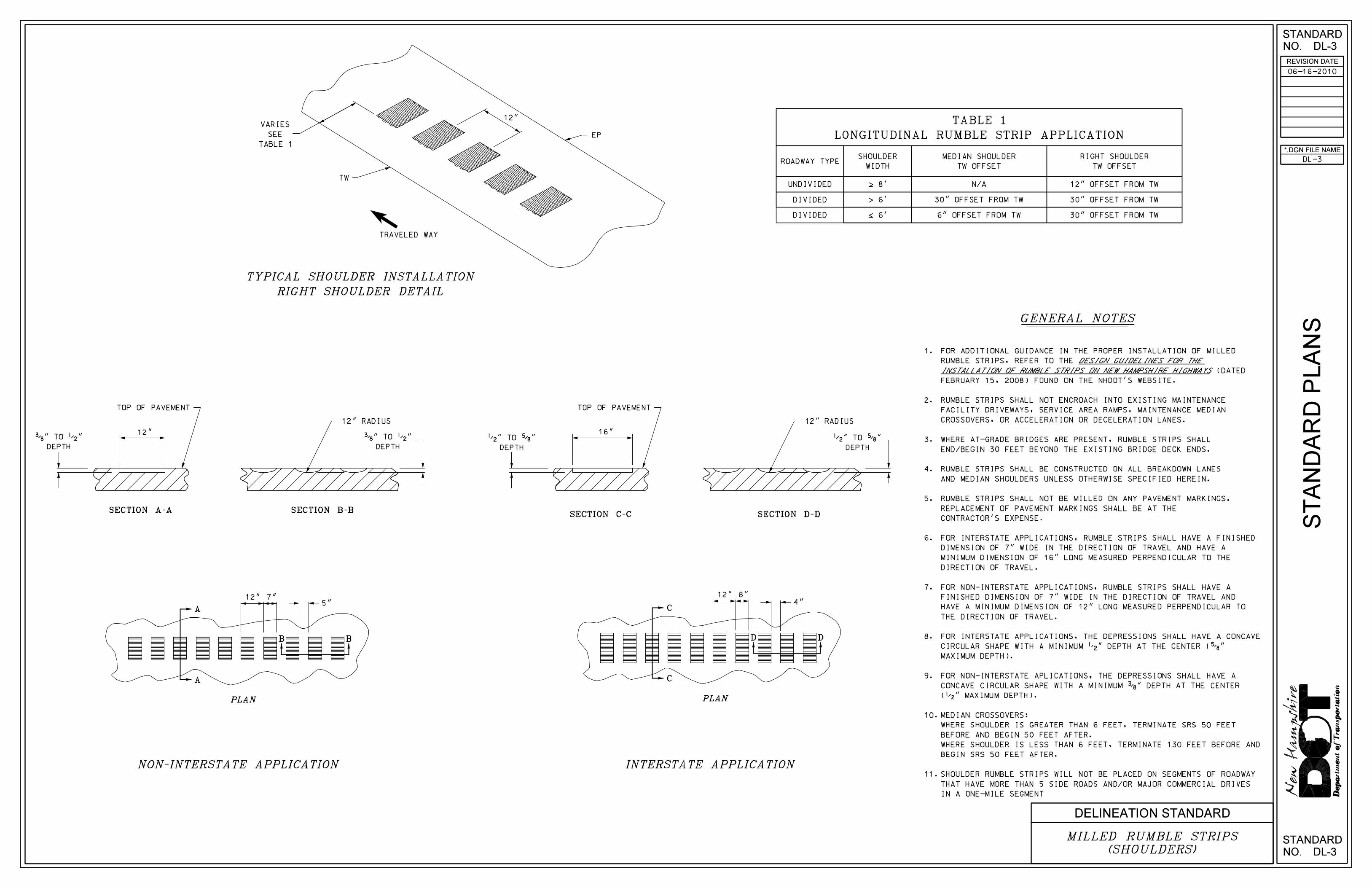
APPENDIX – RUMBLE STRIP STANDARD DETAIL

ST
AN
DA
RD
PL
AN
S
STANDARD
NO.
NO.
STANDARD
REVISION DATE
*.DGN FILE NAME
DL-3
DL-3
DL-3
DELINEATION STANDARD
12"
12" RADIUS
16"
12"
12" RADIUS
12"
TOP OF PAVEMENT
3/8 " TO 1/2 "
DEPTH
1/2 " TO 5/8 "
DEPTH
TOP OF PAVEMENT
3/8 " TO 1/2 "
DEPTH
1/2 " TO 5/8 "
DEPTH
8"7"
ROADWAY TYPESHOULDER
WIDTH
MEDIAN SHOULDER
TW OFFSET
RIGHT SHOULDER
TW OFFSET
UNDIVIDED
DIVIDED
DIVIDED
| 8’
� 6’
\ 6’
N/A
30" OFFSET FROM TW
6" OFFSET FROM TW
12" OFFSET FROM TW
30" OFFSET FROM TW
30" OFFSET FROM TW
TRAVELED WAY
12"VARIES
SEE
TABLE 1
EP
TW
TABLE 1
LONGITUDINAL RUMBLE STRIP APPLICATION
1.
2.
3.
4.
5.
6.
7.
8.
9.
10.
11.
SECTION A-A SECTION B-BSECTION C-C SECTION D-D
D D
C
C
B B
A
A
06-16-2010
4"5"
FOR ADDITIONAL GUIDANCE IN THE PROPER INSTALLATION OF MILLED
RUMBLE STRIPS, REFER TO THE
(DATED
FEBRUARY 15, 2008) FOUND ON THE NHDOT’S WEBSITE.
RUMBLE STRIPS SHALL NOT ENCROACH INTO EXISTING MAINTENANCE
FACILITY DRIVEWAYS, SERVICE AREA RAMPS, MAINTENANCE MEDIAN
CROSSOVERS, OR ACCELERATION OR DECELERATION LANES.
WHERE AT-GRADE BRIDGES ARE PRESENT, RUMBLE STRIPS SHALL
END/BEGIN 30 FEET BEYOND THE EXISTING BRIDGE DECK ENDS.
RUMBLE STRIPS SHALL BE CONSTRUCTED ON ALL BREAKDOWN LANES
AND MEDIAN SHOULDERS UNLESS OTHERWISE SPECIFIED HEREIN.
RUMBLE STRIPS SHALL NOT BE MILLED ON ANY PAVEMENT MARKINGS.
REPLACEMENT OF PAVEMENT MARKINGS SHALL BE AT THE
CONTRACTOR’S EXPENSE.
FOR INTERSTATE APPLICATIONS, RUMBLE STRIPS SHALL HAVE A FINISHED
DIMENSION OF 7" WIDE IN THE DIRECTION OF TRAVEL AND HAVE A
MINIMUM DIMENSION OF 16" LONG MEASURED PERPENDICULAR TO THE
DIRECTION OF TRAVEL.
FOR NON-INTERSTATE APPLICATIONS, RUMBLE STRIPS SHALL HAVE A
FINISHED DIMENSION OF 7" WIDE IN THE DIRECTION OF TRAVEL AND
HAVE A MINIMUM DIMENSION OF 12" LONG MEASURED PERPENDICULAR TO
THE DIRECTION OF TRAVEL.
FOR INTERSTATE APPLICATIONS, THE DEPRESSIONS SHALL HAVE A CONCAVE
CIRCULAR SHAPE WITH A MINIMUM 1/2 " DEPTH AT THE CENTER ( 5/8 "
MAXIMUM DEPTH).
FOR NON-INTERSTATE APLICATIONS, THE DEPRESSIONS SHALL HAVE A
CONCAVE CIRCULAR SHAPE WITH A MINIMUM 3/8 " DEPTH AT THE CENTER
( 1/2 " MAXIMUM DEPTH).
MEDIAN CROSSOVERS:
WHERE SHOULDER IS GREATER THAN 6 FEET, TERMINATE SRS 50 FEET
BEFORE AND BEGIN 50 FEET AFTER.
WHERE SHOULDER IS LESS THAN 6 FEET, TERMINATE 130 FEET BEFORE AND
BEGIN SRS 50 FEET AFTER.
SHOULDER RUMBLE STRIPS WILL NOT BE PLACED ON SEGMENTS OF ROADWAY
THAT HAVE MORE THAN 5 SIDE ROADS AND/OR MAJOR COMMERCIAL DRIVES
IN A ONE-MILE SEGMENT