research, technology, and engineering accomplishments · pdf filearmstrong research,...
TRANSCRIPT
National Aeronautics and Space Administration
2014
Neil A. Armstrong Flight Research Center
Research, Technology, and Engineering Accomplishments
Advancing technology and science through flight
www.nasa.gov NASA/TM-2014-218336
2 ARMSTRONG RESEARCH, TECHNOLOGY, AND ENGINEERING ACCOMPLISHMENTS 2014
From the Director: Research and Engineering Directorate
It’s with great pleasure that I endorse the 2014 Neil A. Armstrong Flight Research Center’s Research, Technology, and Engineering Accomplishments Report. The talented personnel at Armstrong are devoted to making meaningful and significant contributions to the important mission that NASA provides for the Nation. The researchers, engineers, and scientists at Armstrong continue a long, rich legacy of creating innovative approaches to solve some of the difficult problems and challenges facing the aerospace community.
From advanced, lightweight sensing systems to efficient rocket nozzle research to the safe, routine operation of unmanned systems, the work represented in this report highlights the agility of Armstrong to develop technologies embedded in each of NASA’s core missions and, more importantly, technologies that bridge across missions. We’ve long considered one of our key strengths to be the ability to identify emerging yet innovative tools, techniques, and technologies that may be languish-ing in the development process and then rapidly move them into flight evaluation so that we can quickly identify their strengths, shortcomings, and potential applications.
This report presents a brief summary of the technology work of the Center. It also contains contact information for the associated technologists responsible for the work. Don’t hesitate to contact them for more information or for collaboration ideas.
Bradley C. Flick Director for Research and Engineering
3ARMSTRONG RESEARCH, TECHNOLOGY, AND ENGINEERING ACCOMPLISHMENTS 2014
From the Center Chief Technologist
I am pleased to present this report of accomplishments at NASA’s Armstrong Flight Research Center. Our Center draws on a rich history of performance, safety, and technical capability spanning a wide variety of research areas involving aircraft, electronic sensors, instrumentation, environmental and earth science, celestial observations, and much more. Our dedicated innovators not only perform tasks necessary to safely and successfully accomplish Armstrong’s flight research and test missions but also support NASA missions across the entire Agency.
From concept development and experiment formulation to testing, our engineers and scientists craft creative solutions that advance emerging technologies. At the same time, meticulous testing and analysis protocols ensure that we gather critical data to achieve continuous advancements for core NASA capabilities.
The information in this report demonstrates how our talented personnel create and refine innovative flight research techniques that en-compass all phases of flight projects, from highly developed design through development, fabrication, and operations processes. Through this ongoing refinement, we continue to expand our world-class capabilities, which include an expert work force, unrivaled facilities, aircraft and airspace, a diverse and exciting technology portfolio, and supportive infrastructure.
Summaries of each project highlighting key results and benefits of the effort are provided in the following pages. Technology areas for the projects include hyperelastic research and lightweight flexible aircraft, flight and ground experimental test technologies, fiber optic sensing, supersonic flight research, and more. Additional technical information is available in the appendix, as well as contact information for the Principal Investigator of each project.
I am proud of the work we do here at Armstrong and am pleased to share these details with you.
Armstrong welcomes opportunities for partnership and collaboration, so please contact us to learn more about these cutting-edge innovations and how they might align with your needs.
David VoracekCenter Chief Technologist
Supporting this R&D network is a range of assets:
} More than a dozen piloted and autonomous airborne laboratories that benefit from excellent year-round flying weather
} An aircraft integration facility that offers extensive simulation capabilities
} A flight loads laboratory that conducts thermal and mechanical load studies, including ground vibration testing of structural components, instrumentation, and complete flight vehicles
} Fabrication, machine, and sheet-metal shops whose master craftsmen frequently work with exotic alloys and composites
} A unique operations facility with more than 210,000 square feet of hangar space, conference accommodations, and storage, making it ideal for collaboration among visiting researchers and industry
4 ARMSTRONG RESEARCH, TECHNOLOGY, AND ENGINEERING ACCOMPLISHMENTS 2014
ContentsPROJECT SUMMARIES
Hyperelastic Research/Lightweight Flexible AircraftAdaptive Compliant Trailing Edge (ACTE) Flight Experiment ............................................................................ 6Fundamental Hyperelastic Material Study ........................................................................................................ 7X-56A Multi-Utility Technology Testbed (MUTT)................................................................................................ 7Robust Virtual Deformation Control of the X-56A Model .................................................................................. 8Real-Time Structural Overload Control via Control Allocation Optimization ..................................................... 8Inverse Finite Element Method (iFEM) Investigation for Adaptive Structures ................................................... 9Active Control of Tailored Laminates ................................................................................................................. 9Active/Adaptive Flexible Motion Controls with Aeroservoelastic System Uncertainties ................................... 10
Flight and Ground Experimental Test TechnologiesReal-Time Parameter Identification ................................................................................................................... 11Vehicle Integrated Propulsion Research (VIPR) ................................................................................................. 12Dynamic Inertia Measurement Method ............................................................................................................. 12Acoustic Diagnostics of Turbofan Health Monitoring ........................................................................................ 13Hot Ground Vibration Tests ............................................................................................................................... 13Verification and Validation (V&V) Bench Enhancements ................................................................................... 14
Fiber Optic SensingCompact FOSS (cFOSS) ................................................................................................................................... 15Hybrid FOSS (HyFOSS) ..................................................................................................................................... 16Smart Sensing Using Wavelets ......................................................................................................................... 16Determining Applied Load Data with Strain Measurements ............................................................................. 17Strain Sensing for Displacement and 2-D Shape .............................................................................................. 17Cryogenic FOSS (CryoFOSS) ............................................................................................................................ 18High-Temperature Strain Sensing ..................................................................................................................... 18Strain Sensing for Highly Elastic Materials ........................................................................................................ 19Health Monitoring of Flight Structures .............................................................................................................. 19
Supersonic Flight Research Sonic Boom Measurement Techniques ............................................................................................................. 20Cockpit Interactive Sonic Boom Display Avionics (CISBoomDA) ..................................................................... 21Farfield Investigation of No Boom Threshold (FaINT) ....................................................................................... 21Supersonic Boundary Layer Transition II (SBLT II) ............................................................................................ 22Air-to-Air Background-Oriented Schlieren (AirBOS) .......................................................................................... 22Airborne Schlieren Imaging System (ASIS) ....................................................................................................... 23
Collision Avoidance TechnologiesGlobal Elevation Data Adaptive Compression System (GEDACS) .................................................................... 24Improved Ground Collision Avoidance System (iGCAS) for UAVs .................................................................... 25Multi-Level Autonomous Piloting System (MAPS) ............................................................................................ 25
5ARMSTRONG RESEARCH, TECHNOLOGY, AND ENGINEERING ACCOMPLISHMENTS 2014
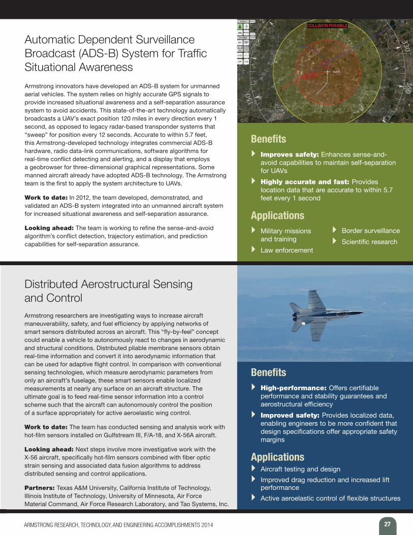
Avionics and Instrumentation TechnologiesPlatform Precision Autopilot (PPA) .................................................................................................................... 26Automatic Dependent Surveillance Broadcast (ADS-B) System for Traffic Situational Awareness .................. 27Distributed Aerostructural Sensing and Control ................................................................................................ 27Portable Data Acquisition SysTem (PDAT) ........................................................................................................ 28Networked Instrumentation ............................................................................................................................... 28Airborne Research Test System, Fourth Generation (ARTS IV) ......................................................................... 29Next-Generation Post-Flight Processing and Analysis with Data Mining Toolset ............................................. 29
Hypersonics and Space TechnologiesAir Launch from a Towed Glider ........................................................................................................................ 30 Altitude Compensating Nozzle (ACN)................................................................................................................ 31Advanced Control Method for Hypersonic Vehicles ......................................................................................... 31Adaptive Guidance Algorithms for Hypersonics ............................................................................................... 32High-Altitude Atmospheric Reconstruction ....................................................................................................... 32Structurally Integrated Thermal Protection System (SITPS) ............................................................................. 33
Efficient Aerospace Vehicle TechnologiesPRANDTL-D Sub-Scale Glider .......................................................................................................................... 34Turbo-Electric Distributed Propulsion Test Stand ............................................................................................. 35Electromagnetic Flow Control to Enable Natural Laminar Flow Wings ............................................................. 35Unmanned Refueling for UAVs .......................................................................................................................... 36Air-to-Air UAV Aerial Refueling .......................................................................................................................... 36Data Fusion to Estimate Vortex Location for Drag Reduction in Formation Flight ........................................... 37Optimized Lift for Autonomous Formation Flight (OLAFF) ................................................................................ 37Peak-Seeking Control for Trim Optimization ..................................................................................................... 38
Low-Carbon Propulsion TechnologyAlternative Fuels’ Effects on Contrails and Cruise Emissions (ACCESS) Flight Experiment ............................ 39
Engineering SuccessesDope on a Rope 2: Development of a Dream Chaser Aero Tow Simulation ..................................................... 41SAFE-Cue to the Rescue! ................................................................................................................................. 42Slideslip-to-Bank Maneuver: A New Flight Test Technique ............................................................................... 42PTERA System Identification Flight Tests ......................................................................................................... 43Abort!...In the Event of an Emergency ............................................................................................................... 44Portable Data Acquisition SysTem (PDAT): Making Ideas Reality ..................................................................... 45Inflatable Structure Testing ................................................................................................................................ 45Capturing the Boom .......................................................................................................................................... 46Flying an Airplane Like a Rocket ....................................................................................................................... 47Masking the Sun and Scoping the Problem ...................................................................................................... 47Precision Path Autopilot (PPA) .......................................................................................................................... 48
Appendix ......................................................................................................................................... 49

6 ARMSTRONG RESEARCH, TECHNOLOGY, AND ENGINEERING ACCOMPLISHMENTS 2014
P R O J E C T S U M M A R I E S Hyperelastic Research/Lightweight
Flexible Aircraft
Armstrong engineers are pioneering new research in aircraft design and modeling. Researchers are experimenting with revolutionary hyperelastic wing
control technologies that can reduce weight, improve aircraft aerodynamic efficiency, and suppress flutter. Other cutting-edge research involves techniques, models, and analysis tools for flutter suppression and gust-load allevia-tion.
Flight projects at Armstrong rely on high-performance aircraft that can support research on lightweight structures and advance control technologies for future efficient, environmentally friendly transport aircraft. This work has applicability beyond flight safety and design optimization. Armstrong’s R&D capabilities in this area also can be applied to other vehicles, such as supersonic transports, large space structures, and hypersonic vehicles.
Adaptive Compliant Trailing Edge (ACTE) Flight Experiment The ACTE experimental flight research project is investigating whether advanced flexible trailing-edge wing flaps can both improve aircraft aerodynamic efficiency and reduce noise associated with takeoffs and landings. The experiment involves replacing the conventional aluminum wing Fowler flaps of a Gulfstream III (G-III) research testbed aircraft with advanced, shape-changing, composite material flaps that form continuous bendable surfaces. The primary goal of the experiment is to collect flight data about the integration and reliability of the composite wing flaps.
Work to date: The G-III has been converted and instrumented into a test platform. The flexible structures have been developed and tested for aircraft applications.
Looking ahead: Flight testing is scheduled to begin in fall 2014. The new flexible wing flaps have arrived at Armstrong, and engineers are preparing them for ground vibration testing, fit checks, and eventual installation. Ultimately, the goal is to work toward developing a wing that incorporates this design from the start, rather than flap integration as has occurred to date.
Partners: FlexSys Inc. designed and built the revolutionary experimental flaps under contract to the U.S. Air Force Research Laboratory. NASA’s Environmentally Responsible Aviation Project is supporting the NASA work.
Benefits } Innovative: Advances compliant structure
technology for use in aircraft to significantly reduce drag, wing weight, and aircraft noise
} Economical: Reduces drag and increases fuel efficiency through the use of an advanced compliant structure
Applications } Aircraft control surfaces } Helicopter blades and wind turbines
7ARMSTRONG RESEARCH, TECHNOLOGY, AND ENGINEERING ACCOMPLISHMENTS 2014
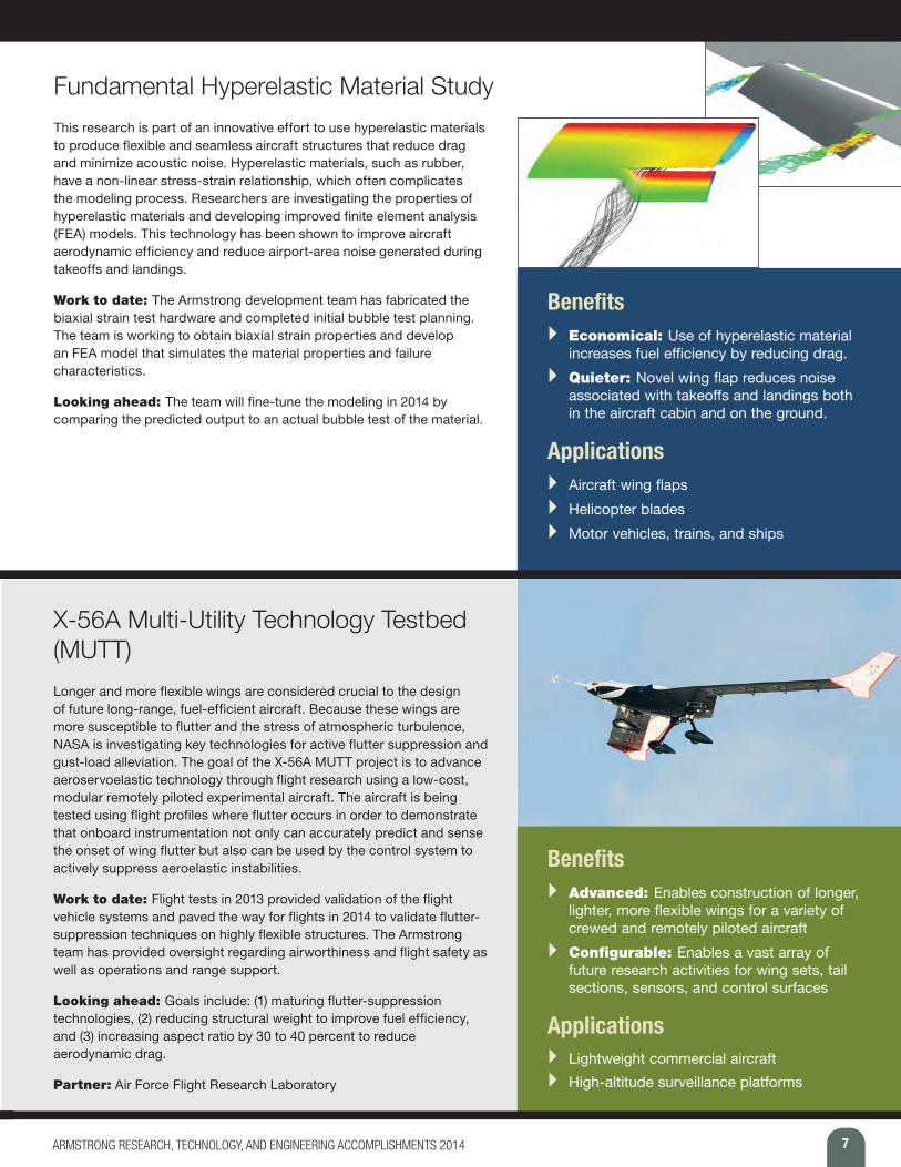
Fundamental Hyperelastic Material Study This research is part of an innovative effort to use hyperelastic materials to produce flexible and seamless aircraft structures that reduce drag and minimize acoustic noise. Hyperelastic materials, such as rubber, have a non-linear stress-strain relationship, which often complicates the modeling process. Researchers are investigating the properties of hyperelastic materials and developing improved finite element analysis (FEA) models. This technology has been shown to improve aircraft aerodynamic efficiency and reduce airport-area noise generated during takeoffs and landings.
Work to date: The Armstrong development team has fabricated the biaxial strain test hardware and completed initial bubble test planning. The team is working to obtain biaxial strain properties and develop an FEA model that simulates the material properties and failure characteristics.
Looking ahead: The team will fine-tune the modeling in 2014 by comparing the predicted output to an actual bubble test of the material.
Benefits } Economical: Use of hyperelastic material
increases fuel efficiency by reducing drag. } Quieter: Novel wing flap reduces noise
associated with takeoffs and landings both in the aircraft cabin and on the ground.
Applications } Aircraft wing flaps } Helicopter blades } Motor vehicles, trains, and ships
X-56A Multi-Utility Technology Testbed (MUTT)Longer and more flexible wings are considered crucial to the design of future long-range, fuel-efficient aircraft. Because these wings are more susceptible to flutter and the stress of atmospheric turbulence, NASA is investigating key technologies for active flutter suppression and gust-load alleviation. The goal of the X-56A MUTT project is to advance aeroservoelastic technology through flight research using a low-cost, modular remotely piloted experimental aircraft. The aircraft is being tested using flight profiles where flutter occurs in order to demonstrate that onboard instrumentation not only can accurately predict and sense the onset of wing flutter but also can be used by the control system to actively suppress aeroelastic instabilities.
Work to date: Flight tests in 2013 provided validation of the flight vehicle systems and paved the way for flights in 2014 to validate flutter-suppression techniques on highly flexible structures. The Armstrong team has provided oversight regarding airworthiness and flight safety as well as operations and range support.
Looking ahead: Goals include: (1) maturing flutter-suppression technologies, (2) reducing structural weight to improve fuel efficiency, and (3) increasing aspect ratio by 30 to 40 percent to reduce aerodynamic drag.
Partner: Air Force Flight Research Laboratory
Benefits } Advanced: Enables construction of longer,
lighter, more flexible wings for a variety of crewed and remotely piloted aircraft
} Configurable: Enables a vast array of future research activities for wing sets, tail sections, sensors, and control surfaces
Applications } Lightweight commercial aircraft } High-altitude surveillance platforms
8 ARMSTRONG RESEARCH, TECHNOLOGY, AND ENGINEERING ACCOMPLISHMENTS 2014
P R O J E C T S U M M A R I E S Hyperelastic Research/Lightweight Flexible Aircraft
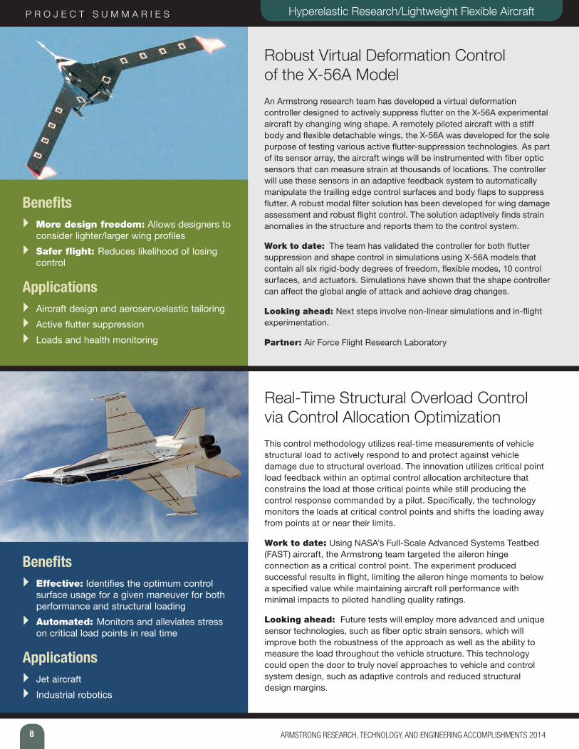
Robust Virtual Deformation Control of the X-56A Model An Armstrong research team has developed a virtual deformation controller designed to actively suppress flutter on the X-56A experimental aircraft by changing wing shape. A remotely piloted aircraft with a stiff body and flexible detachable wings, the X-56A was developed for the sole purpose of testing various active flutter-suppression technologies. As part of its sensor array, the aircraft wings will be instrumented with fiber optic sensors that can measure strain at thousands of locations. The controller will use these sensors in an adaptive feedback system to automatically manipulate the trailing edge control surfaces and body flaps to suppress flutter. A robust modal filter solution has been developed for wing damage assessment and robust flight control. The solution adaptively finds strain anomalies in the structure and reports them to the control system.
Work to date: The team has validated the controller for both flutter suppression and shape control in simulations using X-56A models that contain all six rigid-body degrees of freedom, flexible modes, 10 control surfaces, and actuators. Simulations have shown that the shape controller can affect the global angle of attack and achieve drag changes.
Looking ahead: Next steps involve non-linear simulations and in-flight experimentation.
Partner: Air Force Flight Research Laboratory
Benefits } More design freedom: Allows designers to
consider lighter/larger wing profiles } Safer flight: Reduces likelihood of losing
control
Applications } Aircraft design and aeroservoelastic tailoring } Active flutter suppression } Loads and health monitoring
Real-Time Structural Overload Control via Control Allocation OptimizationThis control methodology utilizes real-time measurements of vehicle structural load to actively respond to and protect against vehicle damage due to structural overload. The innovation utilizes critical point load feedback within an optimal control allocation architecture that constrains the load at those critical points while still producing the control response commanded by a pilot. Specifically, the technology monitors the loads at critical control points and shifts the loading away from points at or near their limits.
Work to date: Using NASA’s Full-Scale Advanced Systems Testbed (FAST) aircraft, the Armstrong team targeted the aileron hinge connection as a critical control point. The experiment produced successful results in flight, limiting the aileron hinge moments to below a specified value while maintaining aircraft roll performance with minimal impacts to piloted handling quality ratings.
Looking ahead: Future tests will employ more advanced and unique sensor technologies, such as fiber optic strain sensors, which will improve both the robustness of the approach as well as the ability to measure the load throughout the vehicle structure. This technology could open the door to truly novel approaches to vehicle and control system design, such as adaptive controls and reduced structural design margins.
Benefits } Effective: Identifies the optimum control
surface usage for a given maneuver for both performance and structural loading
} Automated: Monitors and alleviates stress on critical load points in real time
Applications } Jet aircraft } Industrial robotics
9ARMSTRONG RESEARCH, TECHNOLOGY, AND ENGINEERING ACCOMPLISHMENTS 2014
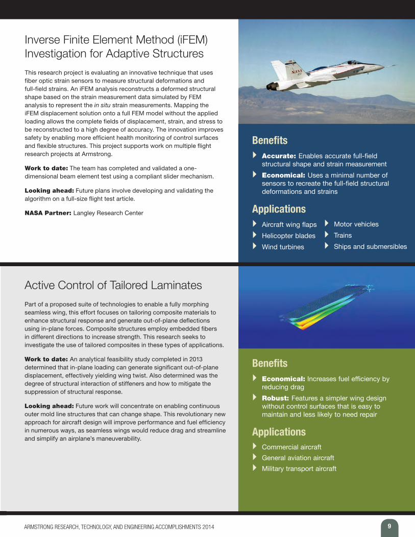
Inverse Finite Element Method (iFEM) Investigation for Adaptive Structures This research project is evaluating an innovative technique that uses fiber optic strain sensors to measure structural deformations and full-field strains. An iFEM analysis reconstructs a deformed structural shape based on the strain measurement data simulated by FEM analysis to represent the in situ strain measurements. Mapping the iFEM displacement solution onto a full FEM model without the applied loading allows the complete fields of displacement, strain, and stress to be reconstructed to a high degree of accuracy. The innovation improves safety by enabling more efficient health monitoring of control surfaces and flexible structures. This project supports work on multiple flight research projects at Armstrong.
Work to date: The team has completed and validated a one-dimensional beam element test using a compliant slider mechanism.
Looking ahead: Future plans involve developing and validating the algorithm on a full-size flight test article.
NASA Partner: Langley Research Center
Benefits } Accurate: Enables accurate full-field
structural shape and strain measurement } Economical: Uses a minimal number of
sensors to recreate the full-field structural deformations and strains
Applications } Aircraft wing flaps } Helicopter blades } Wind turbines
} Motor vehicles } Trains } Ships and submersibles
Active Control of Tailored LaminatesPart of a proposed suite of technologies to enable a fully morphing seamless wing, this effort focuses on tailoring composite materials to enhance structural response and generate out-of-plane deflections using in-plane forces. Composite structures employ embedded fibers in different directions to increase strength. This research seeks to investigate the use of tailored composites in these types of applications.
Work to date: An analytical feasibility study completed in 2013 determined that in-plane loading can generate significant out-of-plane displacement, effectively yielding wing twist. Also determined was the degree of structural interaction of stiffeners and how to mitigate the suppression of structural response.
Looking ahead: Future work will concentrate on enabling continuous outer mold line structures that can change shape. This revolutionary new approach for aircraft design will improve performance and fuel efficiency in numerous ways, as seamless wings would reduce drag and streamline and simplify an airplane’s maneuverability.
Benefits } Economical: Increases fuel efficiency by
reducing drag } Robust: Features a simpler wing design
without control surfaces that is easy to maintain and less likely to need repair
Applications } Commercial aircraft } General aviation aircraft } Military transport aircraft
10 ARMSTRONG RESEARCH, TECHNOLOGY, AND ENGINEERING ACCOMPLISHMENTS 2014
P R O J E C T S U M M A R I E S Hyperelastic Research/Lightweight Flexible Aircraft
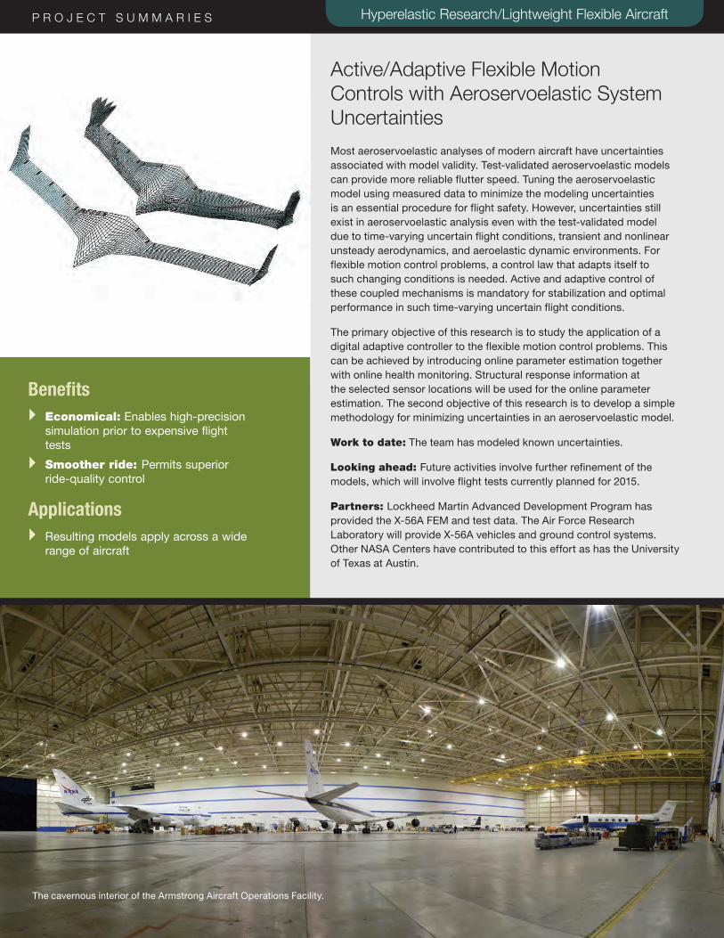
Active/Adaptive Flexible Motion Controls with Aeroservoelastic System Uncertainties Most aeroservoelastic analyses of modern aircraft have uncertainties associated with model validity. Test-validated aeroservoelastic models can provide more reliable flutter speed. Tuning the aeroservoelastic model using measured data to minimize the modeling uncertainties is an essential procedure for flight safety. However, uncertainties still exist in aeroservoelastic analysis even with the test-validated model due to time-varying uncertain flight conditions, transient and nonlinear unsteady aerodynamics, and aeroelastic dynamic environments. For flexible motion control problems, a control law that adapts itself to such changing conditions is needed. Active and adaptive control of these coupled mechanisms is mandatory for stabilization and optimal performance in such time-varying uncertain flight conditions.
The primary objective of this research is to study the application of a digital adaptive controller to the flexible motion control problems. This can be achieved by introducing online parameter estimation together with online health monitoring. Structural response information at the selected sensor locations will be used for the online parameter estimation. The second objective of this research is to develop a simple methodology for minimizing uncertainties in an aeroservoelastic model.
Work to date: The team has modeled known uncertainties.
Looking ahead: Future activities involve further refinement of the models, which will involve flight tests currently planned for 2015.
Partners: Lockheed Martin Advanced Development Program has provided the X-56A FEM and test data. The Air Force Research Laboratory will provide X-56A vehicles and ground control systems. Other NASA Centers have contributed to this effort as has the University of Texas at Austin.
Benefits } Economical: Enables high-precision
simulation prior to expensive flight tests
} Smoother ride: Permits superior ride-quality control
Applications } Resulting models apply across a wide
range of aircraft
The cavernous interior of the Armstrong Aircraft Operations Facility.
11ARMSTRONG RESEARCH, TECHNOLOGY, AND ENGINEERING ACCOMPLISHMENTS 2014
P R O J E C T S U M M A R I E S Flight and Ground Experimental
Test Technologies
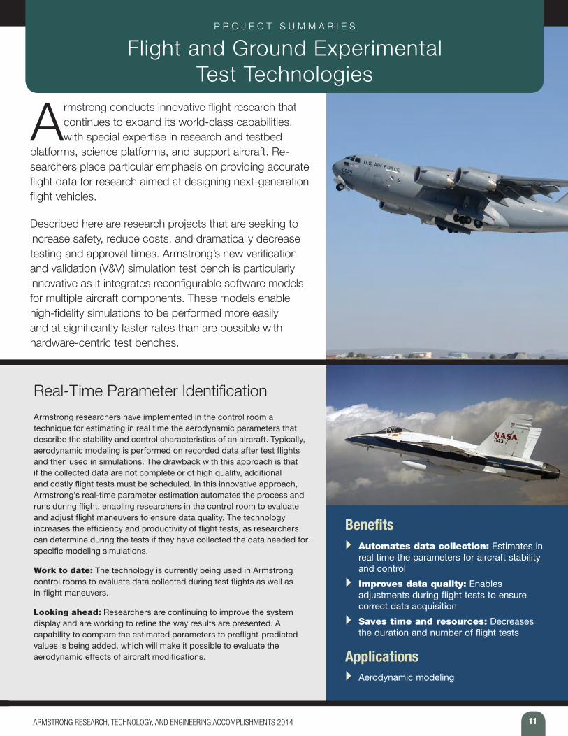
Armstrong conducts innovative flight research that continues to expand its world-class capabilities, with special expertise in research and testbed
platforms, science platforms, and support aircraft. Re-searchers place particular emphasis on providing accurate flight data for research aimed at designing next-generation flight vehicles.
Described here are research projects that are seeking to increase safety, reduce costs, and dramatically decrease testing and approval times. Armstrong’s new verification and validation (V&V) simulation test bench is particularly innovative as it integrates reconfigurable software models for multiple aircraft components. These models enable high-fidelity simulations to be performed more easily and at significantly faster rates than are possible with hardware-centric test benches.
Real-Time Parameter IdentificationArmstrong researchers have implemented in the control room a technique for estimating in real time the aerodynamic parameters that describe the stability and control characteristics of an aircraft. Typically, aerodynamic modeling is performed on recorded data after test flights and then used in simulations. The drawback with this approach is that if the collected data are not complete or of high quality, additional and costly flight tests must be scheduled. In this innovative approach, Armstrong’s real-time parameter estimation automates the process and runs during flight, enabling researchers in the control room to evaluate and adjust flight maneuvers to ensure data quality. The technology increases the efficiency and productivity of flight tests, as researchers can determine during the tests if they have collected the data needed for specific modeling simulations.
Work to date: The technology is currently being used in Armstrong control rooms to evaluate data collected during test flights as well as in-flight maneuvers.
Looking ahead: Researchers are continuing to improve the system display and are working to refine the way results are presented. A capability to compare the estimated parameters to preflight-predicted values is being added, which will make it possible to evaluate the aerodynamic effects of aircraft modifications.
Benefits } Automates data collection: Estimates in
real time the parameters for aircraft stability and control
} Improves data quality: Enables adjustments during flight tests to ensure correct data acquisition
} Saves time and resources: Decreases the duration and number of flight tests
Applications } Aerodynamic modeling
12 ARMSTRONG RESEARCH, TECHNOLOGY, AND ENGINEERING ACCOMPLISHMENTS 2014
P R O J E C T S U M M A R I E S Flight and Ground Experimental Test Technologies
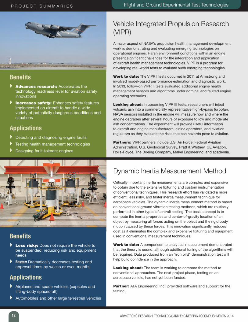
Vehicle Integrated Propulsion Research (VIPR) A major aspect of NASA’s propulsion health management development work is demonstrating and evaluating emerging technologies on operational engines. Harsh environment conditions within an engine present significant challenges for the integration and application of aircraft health management technologies. VIPR is a program for developing real-world tests to evaluate such emerging technologies.
Work to date: The VIPR I tests occurred in 2011 at Armstrong and involved model-based performance estimation and diagnostic work. In 2013, follow-on VIPR II tests evaluated additional engine health management sensors and algorithms under nominal and faulted engine operating scenarios.
Looking ahead: In upcoming VIPR III tests, researchers will inject volcanic ash into a commercially representative high-bypass turbofan. NASA sensors installed in the engine will measure how and where the engine degrades after several hours of exposure to low and moderate ash concentrations. The experiment will provide useful information to aircraft and engine manufacturers, airline operators, and aviation regulators as they evaluate the risks that ash hazards pose to aviation.
Partners: VIPR partners include U.S. Air Force, Federal Aviation Administration, U.S. Geological Survey, Pratt & Whitney, GE Aviation, Rolls-Royce, The Boeing Company, Makel Engineering, and academia.
Benefits } Advances research: Accelerates the
technology readiness level for aviation safety innovations
} Increases safety: Enhances safety features implemented on aircraft to handle a wide variety of potentially dangerous conditions and situations
Applications } Detecting and diagnosing engine faults } Testing health management technologies } Designing fault-tolerant engines
Dynamic Inertia Measurement MethodCritically important inertia measurements are complex and expensive to obtain due to the extensive fixturing and custom instrumentation of conventional techniques. This research effort has validated a more efficient, less risky, and faster inertia measurement technique for aerospace vehicles. The dynamic inertia measurement method is based on conventional ground vibration testing methods, which are routinely performed in other types of aircraft testing. The basic concept is to compute the inertia properties and center-of-gravity location of an object by measuring all forces acting on the object and the rigid body motion caused by these forces. This innovation significantly reduces cost as it eliminates the complex and expensive fixturing and equipment used in conventional measurement techniques.
Work to date: A comparison to analytical measurement demonstrated that the theory is sound, although additional tuning of the algorithms will be required. Data produced from an “iron bird” demonstration test will help build confidence in the approach.
Looking ahead: The team is working to compare the method to conventional approaches. The next project phase, testing on an aerospace vehicle, has not yet been funded.
Partner: ATA Engineering, Inc., provided software and support for the testing.
Benefits } Less risky: Does not require the vehicle to
be suspended, reducing risk and equipment needs
} Faster: Dramatically decreases testing and approval times by weeks or even months
Applications } Airplanes and space vehicles (capsules and
lifting-body spacecraft) } Automobiles and other large terrestrial vehicles
13ARMSTRONG RESEARCH, TECHNOLOGY, AND ENGINEERING ACCOMPLISHMENTS 2014
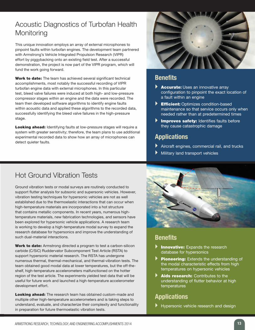
Acoustic Diagnostics of Turbofan Health Monitoring This unique innovation employs an array of external microphones to pinpoint faults within turbofan engines. The development team partnered with Armstrong’s Vehicle Integrated Propulsion Research (VIPR) effort by piggybacking onto an existing field test. After a successful demonstration, the project is now part of the VIPR program, which will fund the work going forward.
Work to date: The team has achieved several significant technical accomplishments, most notably the successful recording of VIPR turbofan engine data with external microphones. In this particular test, bleed valve failures were induced at both high- and low-pressure compressor stages within an engine and the data were recorded. The team then developed software algorithms to identify engine faults within acoustic data and applied these algorithms to the recorded data, successfully identifying the bleed valve failures in the high-pressure stage.
Looking ahead: Identifying faults at low-pressure stages will require a system with greater sensitivity; therefore, the team plans to use additional experimental recorded data to show how an array of microphones can detect quieter faults.
Benefits } Accurate: Uses an innovative array
configuration to pinpoint the exact location of a fault within an engine
} Efficient: Optimizes condition-based maintenance so that service occurs only when needed rather than at predetermined times
} Improves safety: Identifies faults before they cause catastrophic damage
Applications } Aircraft engines, commercial rail, and trucks } Military land transport vehicles
Hot Ground Vibration TestsGround vibration tests or modal surveys are routinely conducted to support flutter analysis for subsonic and supersonic vehicles. However, vibration testing techniques for hypersonic vehicles are not as well established due to the thermoelastic interactions that can occur when high-temperature materials are incorporated into a hot structure that contains metallic components. In recent years, numerous high-temperature materials, new fabrication technologies, and sensors have been explored for hypersonic vehicle applications. A research team is working to develop a high-temperature modal survey to expand the research database for hypersonics and improve the understanding of such dual-material interactions.
Work to date: Armstrong directed a program to test a carbon-silicon carbide (C/SiC) Ruddervator Subcomponent Test Article (RSTA) to support hypersonic material research. The RSTA has undergone numerous thermal, thermal-mechanical, and thermal-vibration tests. The team obtained good modal data at lower temperatures, but the off-the-shelf, high-temperature accelerometers malfunctioned on the hotter region of the test article. The experiments yielded test data that will be useful for future work and launched a high-temperature accelerometer development effort.
Looking ahead: The research team has obtained custom-made and multiple other high-temperature accelerometers and is taking steps to understand, evaluate, and characterize their complexity and functionality in preparation for future thermoelastic vibration tests.
Benefits } Innovative: Expands the research
database for hypersonics } Pioneering: Extends the understanding of
the modal characteristic effects from high temperatures on hypersonic vehicles
} Aids research: Contributes to the understanding of flutter behavior at high temperatures
Applications } Hypersonic vehicle research and design

14 ARMSTRONG RESEARCH, TECHNOLOGY, AND ENGINEERING ACCOMPLISHMENTS 2014
P R O J E C T S U M M A R I E S
Previous test bench
Flight and Ground Experimental Test Technologies
Verification and Validation (V&V) Bench Enhancements Armstrong engineers have developed a new simulation test bench for V&V of software and hardware for the F/A-18 aircraft. The new V&V test bench replaces a bench that was developed more than 30 years ago.
Work to date: The new and more reliable bench is particularly innovative as it integrates reconfigurable software models for multiple aircraft components. These models enable high-fidelity simulations to be performed more easily and at significantly faster rates than were possible using the old hardware-centric test bench. In addition, this approach offers more accurate predictions of behavior.
Looking ahead: The team plans to begin developing the capability to interface with a wide variety of other computers, which in turn will enable simulations of other aircraft such as the F-15 and systems with digital flight control systems.
Benefits } Rapid data collection: Operates at faster
rates, allowing for more detailed modeling } Reconfigurable: Will accommodate other
aircraft via software reconfigurations } Economical: Reduces the number of
expensive flight tests
Applications } F/A-18 and F-15 aircraft } Electric aircraft motors and actuators } Control systems with redundant digital flight
control systems
Simulation technicians install a boilerplate Dream Chaser canopy structure over the cockpit of a flight simulator in the simulation laboratory at NASA’s Armstrong Flight Research Center.
15ARMSTRONG RESEARCH, TECHNOLOGY, AND ENGINEERING ACCOMPLISHMENTS 2014
P R O J E C T S U M M A R I E S Fiber Optic Sensing
A rmstrong’s portfolio of Fiber Optic Sensing System (FOSS) technologies offers unparalleled options for high-resolution sensing in applications that require a unique combination of high-powered
processing and lightweight, flexible, and robust sensors. The system measures real-time strain, which can be used to determine two-dimensional and three-dimensional shape, temperature, liquid level, pressure, and loads, alone or in combination. Initially developed to monitor aircraft structures in flight, the system’s capabilities open up myriad new applications for fiber optics—not just in aerospace but also for civil structures, transportation, oil and gas, medical, and many more industries.
The Armstrong approach employs fiber Bragg grating (FBG) sensors, optical frequency domain reflectometry (OFDR) sensing, and ultra-efficient algo-rithms (100 samples/second). Engineers are continually seeking new ways of looking at information and determining what is important. Armstrong’s FOSS technologies focus on critical research needs. Whether it is used to determine shape, stress, temperature, pressure, strength, operational load, or liquid level, this technology offers ultra-fast, reliable measurements.
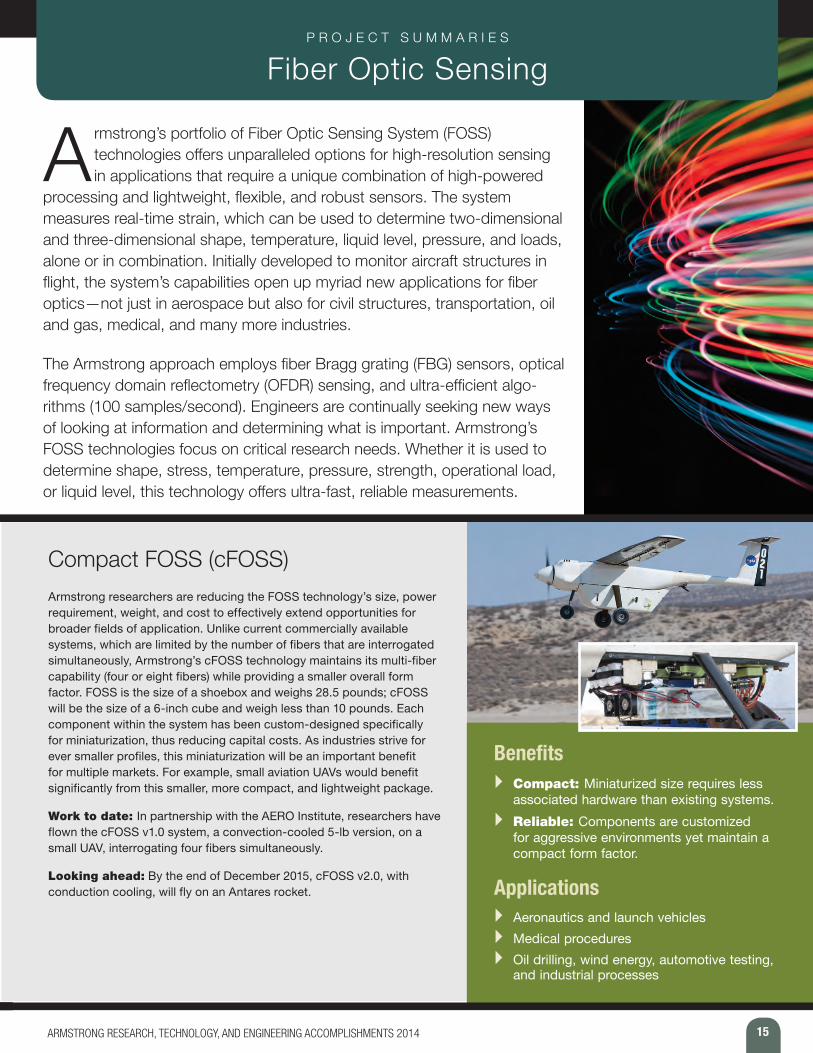
Compact FOSS (cFOSS)Armstrong researchers are reducing the FOSS technology’s size, power requirement, weight, and cost to effectively extend opportunities for broader fields of application. Unlike current commercially available systems, which are limited by the number of fibers that are interrogated simultaneously, Armstrong’s cFOSS technology maintains its multi-fiber capability (four or eight fibers) while providing a smaller overall form factor. FOSS is the size of a shoebox and weighs 28.5 pounds; cFOSS will be the size of a 6-inch cube and weigh less than 10 pounds. Each component within the system has been custom-designed specifically for miniaturization, thus reducing capital costs. As industries strive for ever smaller profiles, this miniaturization will be an important benefit for multiple markets. For example, small aviation UAVs would benefit significantly from this smaller, more compact, and lightweight package.
Work to date: In partnership with the AERO Institute, researchers have flown the cFOSS v1.0 system, a convection-cooled 5-lb version, on a small UAV, interrogating four fibers simultaneously.
Looking ahead: By the end of December 2015, cFOSS v2.0, with conduction cooling, will fly on an Antares rocket.
Benefits } Compact: Miniaturized size requires less
associated hardware than existing systems. } Reliable: Components are customized
for aggressive environments yet maintain a compact form factor.
Applications } Aeronautics and launch vehicles } Medical procedures } Oil drilling, wind energy, automotive testing,
and industrial processes
16 ARMSTRONG RESEARCH, TECHNOLOGY, AND ENGINEERING ACCOMPLISHMENTS 2014
P R O J E C T S U M M A R I E S Fiber Optic Sensing
Hybrid FOSS (HyFOSS) The HyFOSS technique employs conventional continuous grating fibers and then overlays sections every 3 or 4 feet with “strong” gratings that can be sampled at higher rates. The new and stronger gratings can be sampled at rates up to 5,000 hertz (Hz), while the continuous grating sections continue to be sampled at the lower 100-Hz rate. This technique enables higher spatial resolution at specific targets without sacrificing resolution in other areas. The ultimate goal is to achieve sampling rates up to 20 kHz. This increased sampling capability would allow structural features related to high-frequency shock and/or vibration to be captured.
Work to date: The team began investigating the technique in early 2013 after a request from NASA’s Kennedy Space Center to investigate the development effort required to increase the sample rate from 100 Hz to more than 20 kHz. To date, the OFDR technology does not have the capability to achieve these higher sample rates, though the possibility of fusing Wavelength Division Multiplexing (WDM) is feasible yet with limited spatial resolution. Combining the best of OFDR and WDM technologies into new hardware that utilizes the same optical fiber would allow for high spatial resolution with lower sample rates in addition to the ability to obtain high sample rates at strategically spaced points along the fiber.
Looking ahead: Researchers are investigating a 40-foot fiber strand embedded with the new technology in the laboratory environment. The Armstrong team also is investigating the possibilities of pushing the overall sample rate to 20 kHz.
Benefits } More measurements: Offers higher
sampling rates (up to 5 kHz) for specific portions of the fiber
} Fast processing: Collects data at various resolutions without sacrificing speed
Applications } Aeronautics and launch vehicles
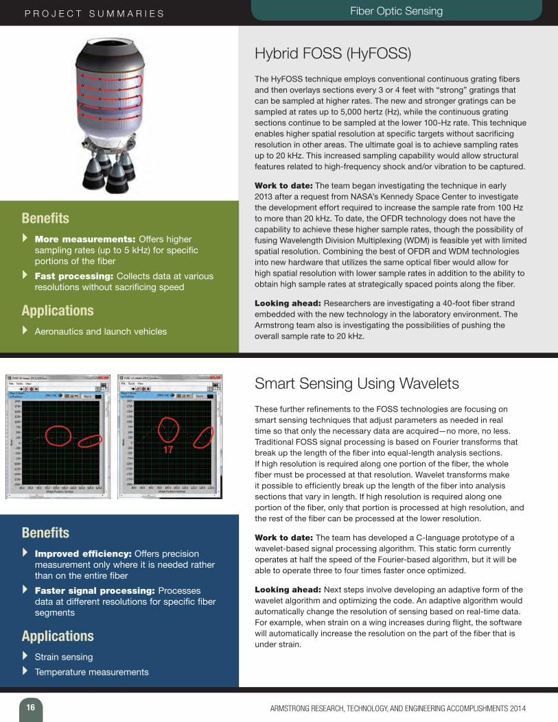
Smart Sensing Using WaveletsThese further refinements to the FOSS technologies are focusing on smart sensing techniques that adjust parameters as needed in real time so that only the necessary data are acquired—no more, no less. Traditional FOSS signal processing is based on Fourier transforms that break up the length of the fiber into equal-length analysis sections. If high resolution is required along one portion of the fiber, the whole fiber must be processed at that resolution. Wavelet transforms make it possible to efficiently break up the length of the fiber into analysis sections that vary in length. If high resolution is required along one portion of the fiber, only that portion is processed at high resolution, and the rest of the fiber can be processed at the lower resolution.
Work to date: The team has developed a C-language prototype of a wavelet-based signal processing algorithm. This static form currently operates at half the speed of the Fourier-based algorithm, but it will be able to operate three to four times faster once optimized.
Looking ahead: Next steps involve developing an adaptive form of the wavelet algorithm and optimizing the code. An adaptive algorithm would automatically change the resolution of sensing based on real-time data. For example, when strain on a wing increases during flight, the software will automatically increase the resolution on the part of the fiber that is under strain.
Benefits } Improved efficiency: Offers precision
measurement only where it is needed rather than on the entire fiber
} Faster signal processing: Processes data at different resolutions for specific fiber segments
Applications } Strain sensing } Temperature measurements
17ARMSTRONG RESEARCH, TECHNOLOGY, AND ENGINEERING ACCOMPLISHMENTS 2014
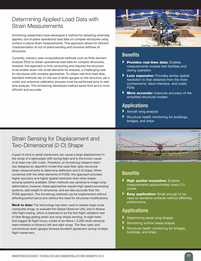
Determining Applied Load Data with Strain Measurements Armstrong researchers have developed a method for obtaining externally applied, out-of-plane operational load data on complex structures using surface in-plane strain measurements. This approach allows for efficient characterization of out-of-plane bending and torsional stiffness of structures.
Currently, industry uses computational methods such as finite element analysis (FEA) to obtain operational load data for complex structures; however, this approach is time consuming and requires the structure to be broken down into small elements for analysis, a challenging task for structures with complex geometries. To obtain real-time load data, standard methods rely on the use of strain gauges on the structure, yet a costly and extensive calibration process must be performed prior to real-time analysis. This Armstrong-developed method saves time and is more efficient and accurate.
Benefits } Provides real-time data: Enables
measurements outside test facilities and during operation
} Less expensive: Provides similar spatial resolution to that obtained from the more cumbersome, labor-intensive, and costly FEAs
} More accurate: Improves accuracy of the simplified structural models
Applications } Aircraft wing analysis } Structural health monitoring for buildings,
bridges, and ships
Strain Sensing for Displacement and Two-Dimensional (2-D) ShapeA gust of wind or aerial maneuvers can cause a large displacement in the wings of a lightweight UAV during flight and is the known cause of at least one UAV crash. Therefore, an Armstrong research team has designed an algorithm model that uses fiber optic structural strain measurements to determine deflection and 2-D shape. When combined with the other elements of FOSS, this approach provides higher accuracy and higher spatial resolution than other shape-sensing systems available. Other methods use cameras to image wing deformation; however, these approaches require high-speed processing systems, add weight to structures, and are less accurate than the FOSS approach. The Armstrong methods can be implemented without affecting performance and without the need for structural modifications.
Work to date: The technology has been used to assess large-scale composite wings, to evaluate the Global Observer UAV, and in Ikhana UAV flight testing, which is believed to be the first flight validation test of fiber Bragg grating strain and wing-shape sensing. In eight tests that logged 36 flight hours, a total of six fibers (~3,000 strain sensors) were installed on Ikhana’s left and right wings. The fiber optic and conventional strain gauges showed excellent agreement during multiple flight maneuvers.
Benefits } High spatial resolution: Enables
measurements approximately every 0.5 inches
} Easy application: Small enough to be used on sensitive surfaces without affecting performance
Applications } Determining aerial wing shapes } Monitoring turbine blade shapes } Structural health monitoring for bridges,
buildings, and ships
18 ARMSTRONG RESEARCH, TECHNOLOGY, AND ENGINEERING ACCOMPLISHMENTS 2014
P R O J E C T S U M M A R I E S Fiber Optic Sensing
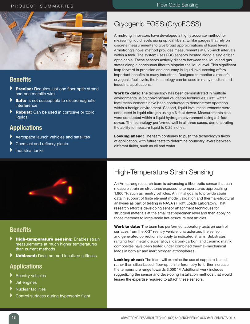
Cryogenic FOSS (CryoFOSS) Armstrong innovators have developed a highly accurate method for measuring liquid levels using optical fibers. Unlike gauges that rely on discrete measurements to give broad approximations of liquid levels, Armstrong’s novel method provides measurements at 0.25-inch intervals within a tank. The system uses FBG sensors located along a single fiber optic cable. These sensors actively discern between the liquid and gas states along a continuous fiber to pinpoint the liquid level. This significant leap forward in precision and accuracy in liquid level sensing offers important benefits to many industries. Designed to monitor a rocket’s cryogenic fuel levels, the technology can be used in many medical and industrial applications.
Work to date: The technology has been demonstrated in multiple environments using conventional validation techniques. First, water level measurements have been conducted to demonstrate operation within a benign environment. Second, liquid level measurements were conducted in liquid nitrogen using a 6-foot dewar. Measurements also were conducted within a liquid hydrogen environment using a 4-foot dewar. The technology performed well in all three cases, demonstrating the ability to measure liquid to 0.25 inches.
Looking ahead: The team continues to push the technology’s fields of application, with future tests to determine boundary layers between different fluids, such as oil and water.
Benefits } Precise: Requires just one fiber optic strand
and one metallic wire } Safe: Is not susceptible to electromagnetic
interference } Robust: Can be used in corrosive or toxic
liquids
Applications } Aerospace launch vehicles and satellites } Chemical and refinery plants } Industrial tanks
High-Temperature Strain SensingAn Armstrong research team is advancing a fiber optic sensor that can measure strain on structures exposed to temperatures approaching 1,800 °F, such as reentry vehicles. An initial goal is to provide strain data in support of finite element model validation and thermal-structural analyses as part of testing in NASA’s Flight Loads Laboratory. That research effort is developing sensor attachment techniques for structural materials at the small test-specimen level and then applying those methods to large-scale hot-structure test articles.
Work to date: The team has performed laboratory tests on control surfaces from the X-37 reentry vehicle, characterized the sensor, and generated corrections to apply to indicated strains. Substrates ranging from metallic super alloys, carbon-carbon, and ceramic matrix composites have been tested under combined thermal-mechanical loads in both air and inert nitrogen atmospheres.
Looking ahead: The team will examine the use of sapphire-based, rather than silica-based, fiber optic interferometry to further increase the temperature range towards 3,000 °F. Additional work includes ruggedizing the sensor and developing installation methods that would lessen the expertise required to attach these sensors.
Benefits } High-temperature sensing: Enables strain
measurements at much higher temperatures than current methods
} Unbiased: Does not add localized stiffness
Applications } Reentry vehicles } Jet engines } Nuclear facilities } Control surfaces during hypersonic flight
19ARMSTRONG RESEARCH, TECHNOLOGY, AND ENGINEERING ACCOMPLISHMENTS 2014
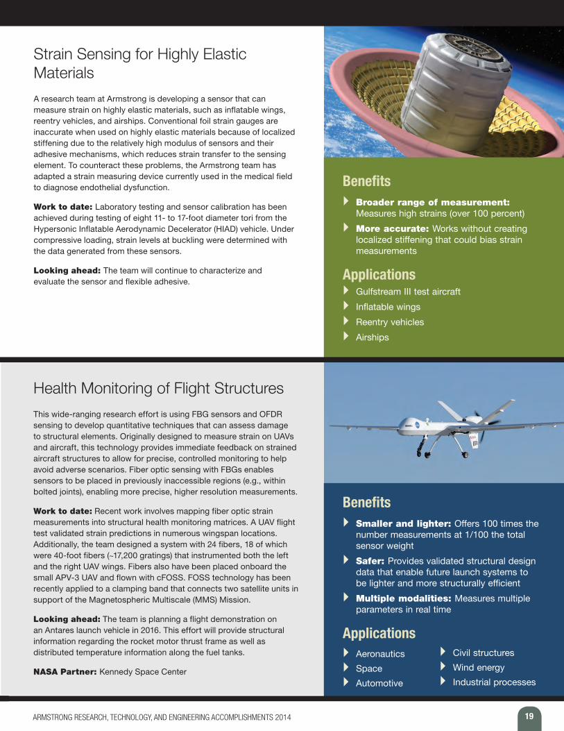
Strain Sensing for Highly Elastic Materials A research team at Armstrong is developing a sensor that can measure strain on highly elastic materials, such as inflatable wings, reentry vehicles, and airships. Conventional foil strain gauges are inaccurate when used on highly elastic materials because of localized stiffening due to the relatively high modulus of sensors and their adhesive mechanisms, which reduces strain transfer to the sensing element. To counteract these problems, the Armstrong team has adapted a strain measuring device currently used in the medical field to diagnose endothelial dysfunction.
Work to date: Laboratory testing and sensor calibration has been achieved during testing of eight 11- to 17-foot diameter tori from the Hypersonic Inflatable Aerodynamic Decelerator (HIAD) vehicle. Under compressive loading, strain levels at buckling were determined with the data generated from these sensors.
Looking ahead: The team will continue to characterize and evaluate the sensor and flexible adhesive.
Benefits } Broader range of measurement:
Measures high strains (over 100 percent) } More accurate: Works without creating
localized stiffening that could bias strain measurements
Applications } Gulfstream III test aircraft } Inflatable wings } Reentry vehicles } Airships
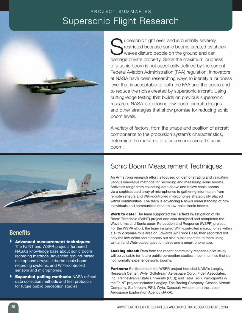
Health Monitoring of Flight Structures This wide-ranging research effort is using FBG sensors and OFDR sensing to develop quantitative techniques that can assess damage to structural elements. Originally designed to measure strain on UAVs and aircraft, this technology provides immediate feedback on strained aircraft structures to allow for precise, controlled monitoring to help avoid adverse scenarios. Fiber optic sensing with FBGs enables sensors to be placed in previously inaccessible regions (e.g., within bolted joints), enabling more precise, higher resolution measurements.
Work to date: Recent work involves mapping fiber optic strain measurements into structural health monitoring matrices. A UAV flight test validated strain predictions in numerous wingspan locations. Additionally, the team designed a system with 24 fibers, 18 of which were 40-foot fibers (~17,200 gratings) that instrumented both the left and the right UAV wings. Fibers also have been placed onboard the small APV-3 UAV and flown with cFOSS. FOSS technology has been recently applied to a clamping band that connects two satellite units in support of the Magnetospheric Multiscale (MMS) Mission.
Looking ahead: The team is planning a flight demonstration on an Antares launch vehicle in 2016. This effort will provide structural information regarding the rocket motor thrust frame as well as distributed temperature information along the fuel tanks.
NASA Partner: Kennedy Space Center
Benefits } Smaller and lighter: Offers 100 times the
number measurements at 1/100 the total sensor weight
} Safer: Provides validated structural design data that enable future launch systems to be lighter and more structurally efficient
} Multiple modalities: Measures multiple parameters in real time
Applications } Aeronautics } Space } Automotive
} Civil structures } Wind energy } Industrial processes
20 ARMSTRONG RESEARCH, TECHNOLOGY, AND ENGINEERING ACCOMPLISHMENTS 2014
P R O J E C T S U M M A R I E S Supersonic Flight Research
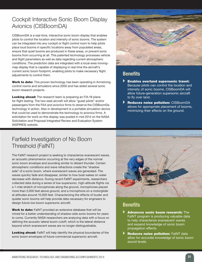
Supersonic flight over land is currently severely restricted because sonic booms created by shock waves disturb people on the ground and can
damage private property. Since the maximum loudness of a sonic boom is not specifically defined by the current Federal Aviation Administration (FAA) regulation, innovators at NASA have been researching ways to identify a loudness level that is acceptable to both the FAA and the public and to reduce the noise created by supersonic aircraft. Using cutting-edge testing that builds on previous supersonic research, NASA is exploring low-boom aircraft designs and other strategies that show promise for reducing sonic boom levels.
A variety of factors, from the shape and position of aircraft components to the propulsion system’s characteristics, determine the make-up of a supersonic aircraft’s sonic boom.
Sonic Boom Measurement Techniques An Armstrong research effort is focused on demonstrating and validating various innovative methods for recording and measuring sonic booms. Activities range from collecting data above and below sonic booms via a sophisticated array of microphones to gathering information from remote sensors and WiFi-controlled microphones strategically placed within communities. The team is advancing NASA’s understanding of how individuals and communities react to low-noise sonic booms.
Work to date: The team supported the Farfield Investigation of No Boom Threshold (FaINT) project and also designed and completed the Waveforms and Sonic boom Perception and Response (WSPR) project. For the WSPR effort, the team installed WiFi-controlled microphones within a 1- to 2-square-mile area on Edwards Air Force Base, then recorded not only the low-noise sonic booms but also public reaction to them using written and Web-based questionnaires and a smart phone app.
Looking ahead: Data from the recent community response pilot study will be valuable for future public perception studies in communities that do not normally experience sonic booms.
Partners: Participants in the WSPR project included NASA’s Langley Research Center; Wyle; Gulfstream Aerospace Corp.; Fidell Associates, Inc.; Pennsylvania State University (PSU); and Tetra Tech. Participants in the FaINT project included Langley, The Boeing Company, Cessna Aircraft Company, Gulfstream, PSU, Wyle, Dassault Aviation, and the Japan Aerospace Exploration Agency (JAXA).
Benefits } Advanced measurement techniques:
The FaINT and WSPR projects furthered NASA’s knowledge base about sonic boom recording methods, advanced ground-based microphone arrays, airborne sonic boom recording systems, and WiFi-controlled sensors and microphones.
} Expanded polling methods: NASA refined data collection methods and test protocols for future public perception studies.
21ARMSTRONG RESEARCH, TECHNOLOGY, AND ENGINEERING ACCOMPLISHMENTS 2014
Cockpit Interactive Sonic Boom Display Avionics (CISBoomDA) CISBoomDA is a real-time, interactive sonic boom display that enables pilots to control the location and intensity of sonic booms. The system can be integrated into any cockpit or flight control room to help pilots place loud booms in specific locations away from populated areas, ensure that quiet booms are produced in these areas, or prevent sonic booms from occurring at all. This patented technology processes vehicle and flight parameters as well as data regarding current atmospheric conditions. The prediction data are integrated with a local-area moving-map display that is capable of displaying in real time the aircraft’s current sonic boom footprint, enabling pilots to make necessary flight adjustments to control them.
Work to date: This proven technology has been operating in Armstrong control rooms and simulators since 2000 and has aided several sonic boom research projects.
Looking ahead: The research team is preparing an F/A-18 plane for flight testing. The two-seat aircraft will allow “guest pilots” and/or passengers from the FAA and avionics firms to observe the CISBoomDa technology in action. Also in development is a portable simulation device that could be used to demonstrate the technology to avionics firms. A solicitation for work on this display was posted in mid 2014 on the NASA Solicitation and Proposal Integrated Review and Evaluation System (NSPIRES) website.
Benefits } Enables overland supersonic travel:
Because pilots can control the location and intensity of sonic booms, CISBoomDA will allow future-generation supersonic aircraft to fly over land.
} Reduces noise pollution: CISBoomDA allows for appropriate placement of booms, minimizing their effects on the ground.
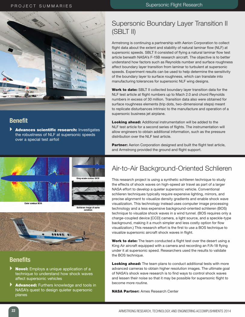
Farfield Investigation of No Boom Threshold (FaINT)The FaINT research project is seeking to characterize evanescent waves, an acoustic phenomenon occurring at the very edges of the normal sonic boom envelope and sounding similar to distant thunder. Certain atmospheric conditions and wave refractions create the “shadow side” of a sonic boom, where evanescent waves are generated. The waves quickly fade and disappear, similar to how boat wakes on water decrease with distance. During recent FaINT experiments, researchers collected data during a series of low-supersonic, high-altitude flights via a 1-mile stretch of microphones along the ground, microphones placed more than 2,000 feet above ground, and a microphone on a motorglider at altitudes around 10,000 feet. Characterizing the effects of louder and quieter sonic booms will help provide data necessary for engineers to design future low-boom supersonic aircraft.
Work to date: FaINT provided an extensive database that will be mined for a better understanding of shadow-side sonic booms for years to come. Currently NASA researchers are analyzing data with a focus on defining the acoustic lateral boom cutoff, which is the lateral distance beyond which evanescent waves are no longer distinguishable.
Looking ahead: FaINT will help identify the physical boundaries of the sonic boom envelopes of future commercial supersonic aircraft.
Benefits } Advances sonic boom research: The
FaINT program is producing valuable data to help characterize evanescent waves and expand knowledge of sonic boom propagation effects.
} Reduces noise pollution: FaINT data allow for accurate knowledge of sonic boom sound levels.
22 ARMSTRONG RESEARCH, TECHNOLOGY, AND ENGINEERING ACCOMPLISHMENTS 2014
P R O J E C T S U M M A R I E S Supersonic Flight Research
Supersonic Boundary Layer Transition II (SBLT II) Armstrong is continuing a partnership with Aerion Corporation to collect flight data about the extent and stability of natural laminar flow (NLF) at supersonic speeds. SBLT II consisted of flying a natural laminar flow test article beneath NASA’s F-15B research aircraft. The objective is to better understand how factors such as Reynolds number and surface roughness affect boundary layer transition from laminar to turbulent at supersonic speeds. Experiment results can be used to help determine the sensitivity of the boundary layer to surface roughness, which can translate into manufacturing tolerances for supersonic NLF wing designs.
Work to date: SBLT II collected boundary layer transition data for the NLF test article at flight numbers up to Mach 2.0 and chord Reynolds numbers in excess of 30 million. Transition data also were obtained for surface roughness elements (trip dots, two-dimensional steps) meant to replicate disturbances intrinsic to the manufacture and operation of a supersonic business jet airplane.
Looking ahead: Additional instrumentation will be added to the NLF test article for a second series of flights. The instrumentation will allow engineers to obtain additional information, such as the pressure distribution over the NLF test article.
Partner: Aerion Corporation designed and built the flight test article, and Armstrong provided the ground and flight support.
Benefit } Advances scientific research: Investigates
the robustness of NLF at supersonic speeds over a special test airfoil
Air-to-Air Background-Oriented SchlierenThis research project is using a synthetic schlieren technique to study the effects of shock waves on high-speed air travel as part of a larger NASA effort to develop a quieter supersonic vehicle. Conventional schlieren techniques typically require expensive lighting, mirrors, and precise alignment to visualize density gradients and enable shock wave visualization. This technology instead uses computer image processing technology and a less expensive background-oriented schlieren (BOS) technique to visualize shock waves in a wind tunnel. (BOS requires only a charge-coupled device [CCD] camera, a light source, and a speckle-type background, making it a much simpler and less costly option for flow visualization.) This research effort is the first to use a BOS technique to visualize supersonic aircraft shock waves in flight.
Work to date: The team conducted a flight test over the desert using a King Air aircraft equipped with a camera and recording an F/A-18 flying under it at supersonic speed. Researchers used the results to validate the BOS technique.
Looking ahead: The team plans to conduct additional tests with more advanced cameras to obtain higher resolution images. The ultimate goal of NASA’s shock wave research is to find ways to control shock waves and lessen their noise so that it may be possible for supersonic flight to become more routine.
NASA Partner: Ames Research Center
Benefits } Novel: Employs a unique application of a
technique to understand how shock waves affect supersonic vehicles
} Advanced: Furthers knowledge and tools in NASA’s quest to design quieter supersonic planes
23ARMSTRONG RESEARCH, TECHNOLOGY, AND ENGINEERING ACCOMPLISHMENTS 2014
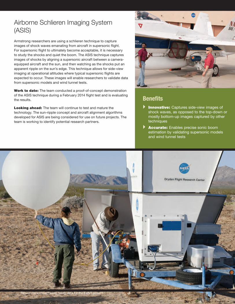
Airborne Schlieren Imaging System (ASIS) Armstrong researchers are using a schlieren technique to capture images of shock waves emanating from aircraft in supersonic flight. For supersonic flight to ultimately become acceptable, it is necessary to study the shocks and quiet the boom. The ASIS technique captures images of shocks by aligning a supersonic aircraft between a camera-equipped aircraft and the sun, and then watching as the shocks put an apparent ripple on the sun’s edge. This technique allows for side-view imaging at operational altitudes where typical supersonic flights are expected to occur. These images will enable researchers to validate data from supersonic models and wind tunnel tests.
Work to date: The team conducted a proof-of-concept demonstration of the ASIS technique during a February 2014 flight test and is evaluating the results.
Looking ahead: The team will continue to test and mature the technology. The sun-ripple concept and aircraft alignment algorithms developed for ASIS are being considered for use on future projects. The team is working to identify potential research partners.
Benefits } Innovative: Captures side-view images of
shock waves, as opposed to the top-down or mostly bottom-up images captured by other techniques
} Accurate: Enables precise sonic boom estimation by validating supersonic models and wind tunnel tests
Researchers collect sonic boom data for the FaINT project.
24 ARMSTRONG RESEARCH, TECHNOLOGY, AND ENGINEERING ACCOMPLISHMENTS 2014
P R O J E C T S U M M A R I E S Collision Avoidance Technologies
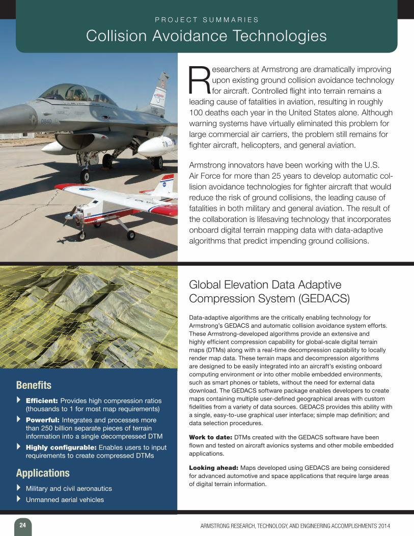
Researchers at Armstrong are dramatically improving upon existing ground collision avoidance technology for aircraft. Controlled flight into terrain remains a
leading cause of fatalities in aviation, resulting in roughly 100 deaths each year in the United States alone. Although warning systems have virtually eliminated this problem for large commercial air carriers, the problem still remains for fighter aircraft, helicopters, and general aviation.
Armstrong innovators have been working with the U.S. Air Force for more than 25 years to develop automatic col-lision avoidance technologies for fighter aircraft that would reduce the risk of ground collisions, the leading cause of fatalities in both military and general aviation. The result of the collaboration is lifesaving technology that incorporates onboard digital terrain mapping data with data-adaptive algorithms that predict impending ground collisions.
Global Elevation Data Adaptive Compression System (GEDACS) Data-adaptive algorithms are the critically enabling technology for Armstrong’s GEDACS and automatic collision avoidance system efforts. These Armstrong-developed algorithms provide an extensive and highly efficient compression capability for global-scale digital terrain maps (DTMs) along with a real-time decompression capability to locally render map data. These terrain maps and decompression algorithms are designed to be easily integrated into an aircraft’s existing onboard computing environment or into other mobile embedded environments, such as smart phones or tablets, without the need for external data download. The GEDACS software package enables developers to create maps containing multiple user-defined geographical areas with custom fidelities from a variety of data sources. GEDACS provides this ability with a single, easy-to-use graphical user interface; simple map definition; and data selection procedures.
Work to date: DTMs created with the GEDACS software have been flown and tested on aircraft avionics systems and other mobile embedded applications.
Looking ahead: Maps developed using GEDACS are being considered for advanced automotive and space applications that require large areas of digital terrain information.
Benefits } Efficient: Provides high compression ratios
(thousands to 1 for most map requirements) } Powerful: Integrates and processes more
than 250 billion separate pieces of terrain information into a single decompressed DTM
} Highly configurable: Enables users to input requirements to create compressed DTMs
Applications } Military and civil aeronautics } Unmanned aerial vehicles
25ARMSTRONG RESEARCH, TECHNOLOGY, AND ENGINEERING ACCOMPLISHMENTS 2014
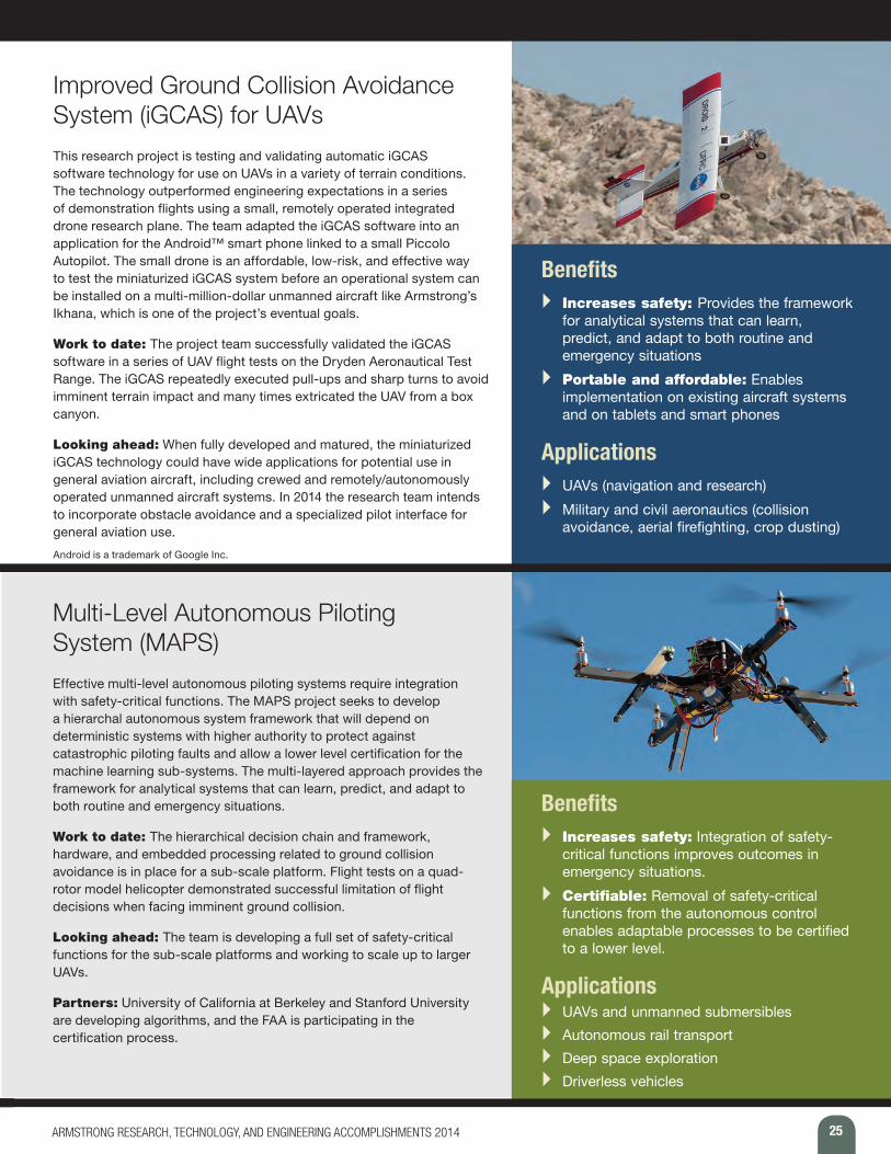
Improved Ground Collision Avoidance System (iGCAS) for UAVs This research project is testing and validating automatic iGCAS software technology for use on UAVs in a variety of terrain conditions. The technology outperformed engineering expectations in a series of demonstration flights using a small, remotely operated integrated drone research plane. The team adapted the iGCAS software into an application for the Android™ smart phone linked to a small Piccolo Autopilot. The small drone is an affordable, low-risk, and effective way to test the miniaturized iGCAS system before an operational system can be installed on a multi-million-dollar unmanned aircraft like Armstrong’s Ikhana, which is one of the project’s eventual goals.
Work to date: The project team successfully validated the iGCAS software in a series of UAV flight tests on the Dryden Aeronautical Test Range. The iGCAS repeatedly executed pull-ups and sharp turns to avoid imminent terrain impact and many times extricated the UAV from a box canyon.
Looking ahead: When fully developed and matured, the miniaturized iGCAS technology could have wide applications for potential use in general aviation aircraft, including crewed and remotely/autonomously operated unmanned aircraft systems. In 2014 the research team intends to incorporate obstacle avoidance and a specialized pilot interface for general aviation use.
Android is a trademark of Google Inc.
Benefits } Increases safety: Provides the framework
for analytical systems that can learn, predict, and adapt to both routine and emergency situations
} Portable and affordable: Enables implementation on existing aircraft systems and on tablets and smart phones
Applications } UAVs (navigation and research) } Military and civil aeronautics (collision
avoidance, aerial firefighting, crop dusting)
Multi-Level Autonomous Piloting System (MAPS)Effective multi-level autonomous piloting systems require integration with safety-critical functions. The MAPS project seeks to develop a hierarchal autonomous system framework that will depend on deterministic systems with higher authority to protect against catastrophic piloting faults and allow a lower level certification for the machine learning sub-systems. The multi-layered approach provides the framework for analytical systems that can learn, predict, and adapt to both routine and emergency situations.
Work to date: The hierarchical decision chain and framework, hardware, and embedded processing related to ground collision avoidance is in place for a sub-scale platform. Flight tests on a quad-rotor model helicopter demonstrated successful limitation of flight decisions when facing imminent ground collision.
Looking ahead: The team is developing a full set of safety-critical functions for the sub-scale platforms and working to scale up to larger UAVs.
Partners: University of California at Berkeley and Stanford University are developing algorithms, and the FAA is participating in the certification process.
Benefits } Increases safety: Integration of safety-
critical functions improves outcomes in emergency situations.
} Certifiable: Removal of safety-critical functions from the autonomous control enables adaptable processes to be certified to a lower level.
Applications } UAVs and unmanned submersibles } Autonomous rail transport } Deep space exploration } Driverless vehicles
26 ARMSTRONG RESEARCH, TECHNOLOGY, AND ENGINEERING ACCOMPLISHMENTS 2014
P R O J E C T S U M M A R I E S Avionics and Instrumentation Technologies
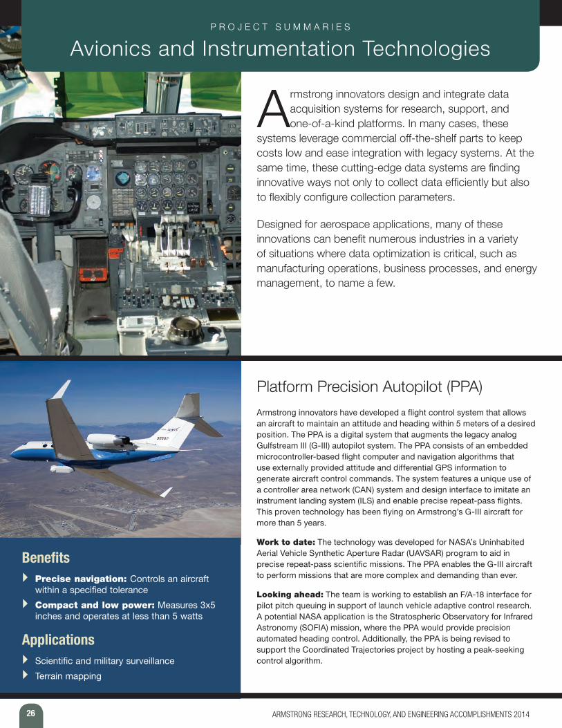
Armstrong innovators design and integrate data acquisition systems for research, support, and one-of-a-kind platforms. In many cases, these
systems leverage commercial off-the-shelf parts to keep costs low and ease integration with legacy systems. At the same time, these cutting-edge data systems are finding innovative ways not only to collect data efficiently but also to flexibly configure collection parameters.
Designed for aerospace applications, many of these innovations can benefit numerous industries in a variety of situations where data optimization is critical, such as manufacturing operations, business processes, and energy management, to name a few.
Platform Precision Autopilot (PPA) Armstrong innovators have developed a flight control system that allows an aircraft to maintain an attitude and heading within 5 meters of a desired position. The PPA is a digital system that augments the legacy analog Gulfstream III (G-III) autopilot system. The PPA consists of an embedded microcontroller-based flight computer and navigation algorithms that use externally provided attitude and differential GPS information to generate aircraft control commands. The system features a unique use of a controller area network (CAN) system and design interface to imitate an instrument landing system (ILS) and enable precise repeat-pass flights. This proven technology has been flying on Armstrong’s G-III aircraft for more than 5 years.
Work to date: The technology was developed for NASA’s Uninhabited Aerial Vehicle Synthetic Aperture Radar (UAVSAR) program to aid in precise repeat-pass scientific missions. The PPA enables the G-III aircraft to perform missions that are more complex and demanding than ever.
Looking ahead: The team is working to establish an F/A-18 interface for pilot pitch queuing in support of launch vehicle adaptive control research. A potential NASA application is the Stratospheric Observatory for Infrared Astronomy (SOFIA) mission, where the PPA would provide precision automated heading control. Additionally, the PPA is being revised to support the Coordinated Trajectories project by hosting a peak-seeking control algorithm.
Benefits } Precise navigation: Controls an aircraft
within a specified tolerance } Compact and low power: Measures 3x5
inches and operates at less than 5 watts
Applications } Scientific and military surveillance } Terrain mapping
27ARMSTRONG RESEARCH, TECHNOLOGY, AND ENGINEERING ACCOMPLISHMENTS 2014
Automatic Dependent Surveillance Broadcast (ADS-B) System for Traffic Situational Awareness Armstrong innovators have developed an ADS-B system for unmanned aerial vehicles. The system relies on highly accurate GPS signals to provide increased situational awareness and a self-separation assurance system to avoid accidents. This state-of-the-art technology automatically broadcasts a UAV’s exact position 120 miles in every direction every 1 second, as opposed to legacy radar-based transponder systems that “sweep” for position every 12 seconds. Accurate to within 5.7 feet, this Armstrong-developed technology integrates commercial ADS-B hardware, radio data-link communications, software algorithms for real-time conflict detecting and alerting, and a display that employs a geobrowser for three-dimensional graphical representations. Some manned aircraft already have adopted ADS-B technology. The Armstrong team is the first to apply the system architecture to UAVs.
Work to date: In 2012, the team developed, demonstrated, and validated an ADS-B system integrated into an unmanned aircraft system for increased situational awareness and self-separation assurance.
Looking ahead: The team is working to refine the sense-and-avoid algorithm’s conflict detection, trajectory estimation, and prediction capabilities for self-separation assurance.
Benefits } Improves safety: Enhances sense-and-
avoid capabilities to maintain self-separation for UAVs
} Highly accurate and fast: Provides location data that are accurate to within 5.7 feet every 1 second
Applications } Military missions
and training } Law enforcement
} Border surveillance } Scientific research
Distributed Aerostructural Sensing and ControlArmstrong researchers are investigating ways to increase aircraft maneuverability, safety, and fuel efficiency by applying networks of smart sensors distributed across an aircraft. This “fly-by-feel” concept could enable a vehicle to autonomously react to changes in aerodynamic and structural conditions. Distributed pliable membrane sensors obtain real-time information and convert it into aerodynamic information that can be used for adaptive flight control. In comparison with conventional sensing technologies, which measure aerodynamic parameters from only an aircraft’s fuselage, these smart sensors enable localized measurements at nearly any surface on an aircraft structure. The ultimate goal is to feed real-time sensor information into a control scheme such that the aircraft can autonomously control the position of a surface appropriately for active aeroelastic wing control.
Work to date: The team has conducted sensing and analysis work with hot-film sensors installed on Gulfstream III, F/A-18, and X-56A aircraft.
Looking ahead: Next steps involve more investigative work with the X-56 aircraft, specifically hot-film sensors combined with fiber optic strain sensing and associated data fusion algorithms to address distributed sensing and control applications.
Partners: Texas A&M University, California Institute of Technology, Illinois Institute of Technology, University of Minnesota, Air Force Material Command, Air Force Research Laboratory, and Tao Systems, Inc.
Benefits } High-performance: Offers certifiable
performance and stability guarantees and aerostructural efficiency
} Improved safety: Provides localized data, enabling engineers to be more confident that design specifications offer appropriate safety margins
Applications } Aircraft testing and design } Improved drag reduction and increased lift
performance } Active aeroelastic control of flexible structures
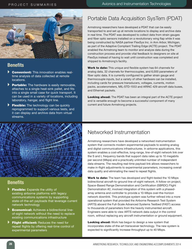
28 ARMSTRONG RESEARCH, TECHNOLOGY, AND ENGINEERING ACCOMPLISHMENTS 2014
P R O J E C T S U M M A R I E S Avionics and Instrumentation Technologies
Portable Data Acquisition SysTem (PDAT) Armstrong researchers have developed a PDAT that can be easily transported to and set up at remote locations to display and archive data in real time. The PDAT was developed to collect data from strain gauges and fiber optic sensors installed on a revolutionary wing flap while it was being constructed by NASA partner FlexSys Inc. in Ann Arbor, Michigan, as part of the Adaptive Compliant Trailing Edge (ACTE) project. The PDAT enabled the Armstrong team to monitor and analyze data during the construction process and provide vital feedback to designers on site at FlexSys instead of having to wait until construction was completed and shipped to Armstrong’s facility.
Work to date: This unique and flexible system has 64 channels for analog data, 32 channels for thermocouples, and 6,000 parameters of fiber optic data. It is currently configured to gather strain gauge and thermocouple inputs, but a variety of other hardware can be installed, including cards for pressure transducers, voltages, currents, motion packs, accelerometers, MIL-STD-1553 and ARINC 429 aircraft data buses, and Ethernet packets.
Looking ahead: The PDAT has been an integral part of the ACTE project and is versatile enough to become a successful component of many current and future Armstrong projects.
Benefits } Convenient: This innovation enables real-
time analysis of data collected at remote locations.
} Portable: The hardware is easily removable, attaches to a single heat-sink pallet, and fits into a single small case for quick transport. It can be used in a variety of locations, including laboratory, hangar, and flight line.
} Flexible: The technology can be quickly reprogrammed to support various tests, and it can display and archive data from virtual streams.
Networked InstrumentationArmstrong researchers have developed a networked instrumentation system that connects modern experimental payloads to existing analog and digital communications infrastructures. In airborne applications, this system enables a cost-effective, long-range, line-of-sight network link over the S and L frequency bands that support data rates up to 10 megabits per second (Mbps) and a practically unlimited number of independent data streams. The resulting real-time payload link allows researchers to make in-flight adjustments to experimental parameters, increasing overall data quality and eliminating the need to repeat flights.
Work to date: The team has developed and flight-tested the 10 Mbps bidirectional aircraft-to-ground line-of-sight network. A follow-on project, Space-Based Range Demonstration and Certification (SBRDC) Flight Demonstration #2, involved integration of this system with a phased-array antenna and controller to provide a 10-Mbps over-the-horizon network downlink. This prototype system was further refined into a more operational system that provided the Airborne Research Test System (ARTS) aboard the Full-Scale Advanced Systems Testbed (FAST) access to thousands of parameters from the heavily instrumented aircraft. Engineers were able to view ARTS network data output in the control room, without replacing any aircraft instrumentation or ground equipment.
Looking ahead: Work has begun to design a new system that incorporates state-of-the-art transceiver technology. The new system is expected to significantly increase throughput up to 40 Mbps.
Benefits } Flexible: Expands the utility of
existing airborne platforms with legacy communications systems by supporting state-of-the-art payloads that leverage current network technology
} Economical: Achieves a bidirectional line-of-sight network without the need to replace existing communications infrastructure
} Flight efficient: Reduces the need for repeat flights by offering real-time control of experimental parameters
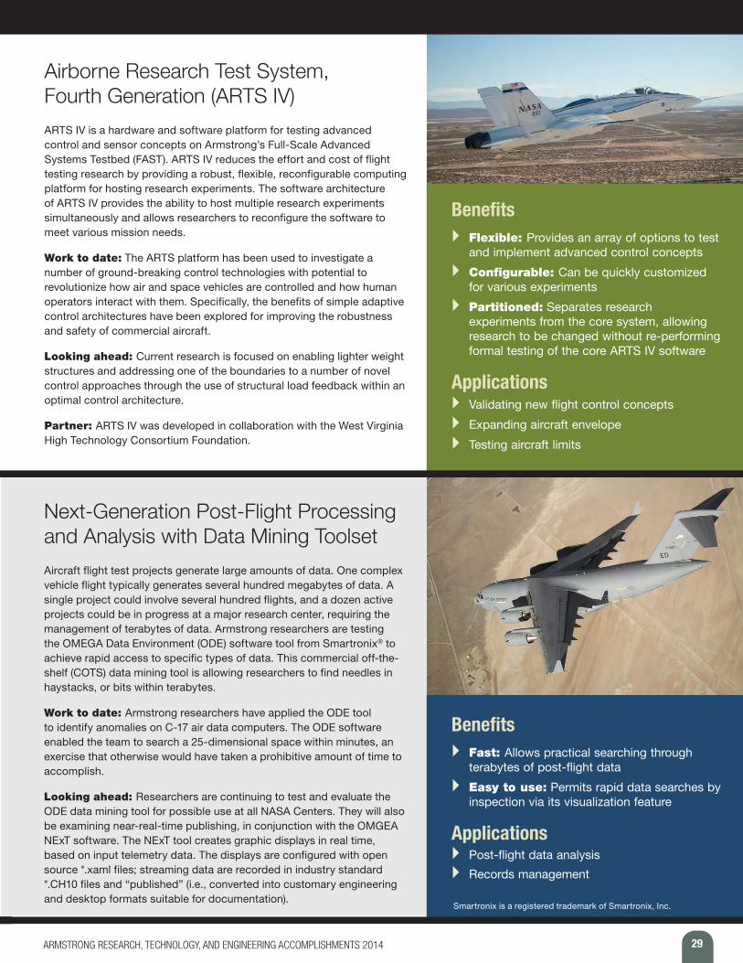
29
Airborne Research Test System, Fourth Generation (ARTS IV) ARTS IV is a hardware and software platform for testing advanced control and sensor concepts on Armstrong’s Full-Scale Advanced Systems Testbed (FAST). ARTS IV reduces the effort and cost of flight testing research by providing a robust, flexible, reconfigurable computing platform for hosting research experiments. The software architecture of ARTS IV provides the ability to host multiple research experiments simultaneously and allows researchers to reconfigure the software to meet various mission needs.
Work to date: The ARTS platform has been used to investigate a number of ground-breaking control technologies with potential to revolutionize how air and space vehicles are controlled and how human operators interact with them. Specifically, the benefits of simple adaptive control architectures have been explored for improving the robustness and safety of commercial aircraft.
Looking ahead: Current research is focused on enabling lighter weight structures and addressing one of the boundaries to a number of novel control approaches through the use of structural load feedback within an optimal control architecture.
Partner: ARTS IV was developed in collaboration with the West Virginia High Technology Consortium Foundation.
Benefits } Flexible: Provides an array of options to test
and implement advanced control concepts } Configurable: Can be quickly customized
for various experiments } Partitioned: Separates research
experiments from the core system, allowing research to be changed without re-performing formal testing of the core ARTS IV software
Applications } Validating new flight control concepts } Expanding aircraft envelope } Testing aircraft limits
Next-Generation Post-Flight Processing and Analysis with Data Mining ToolsetAircraft flight test projects generate large amounts of data. One complex vehicle flight typically generates several hundred megabytes of data. A single project could involve several hundred flights, and a dozen active projects could be in progress at a major research center, requiring the management of terabytes of data. Armstrong researchers are testing the OMEGA Data Environment (ODE) software tool from Smartronix® to achieve rapid access to specific types of data. This commercial off-the-shelf (COTS) data mining tool is allowing researchers to find needles in haystacks, or bits within terabytes.
Work to date: Armstrong researchers have applied the ODE tool to identify anomalies on C-17 air data computers. The ODE software enabled the team to search a 25-dimensional space within minutes, an exercise that otherwise would have taken a prohibitive amount of time to accomplish.
Looking ahead: Researchers are continuing to test and evaluate the ODE data mining tool for possible use at all NASA Centers. They will also be examining near-real-time publishing, in conjunction with the OMGEA NExT software. The NExT tool creates graphic displays in real time, based on input telemetry data. The displays are configured with open source *.xaml files; streaming data are recorded in industry standard *.CH10 files and “published” (i.e., converted into customary engineering and desktop formats suitable for documentation).
Benefits } Fast: Allows practical searching through
terabytes of post-flight data } Easy to use: Permits rapid data searches by
inspection via its visualization feature
Applications } Post-flight data analysis } Records management
Smartronix is a registered trademark of Smartronix, Inc.
ARMSTRONG RESEARCH, TECHNOLOGY, AND ENGINEERING ACCOMPLISHMENTS 2014
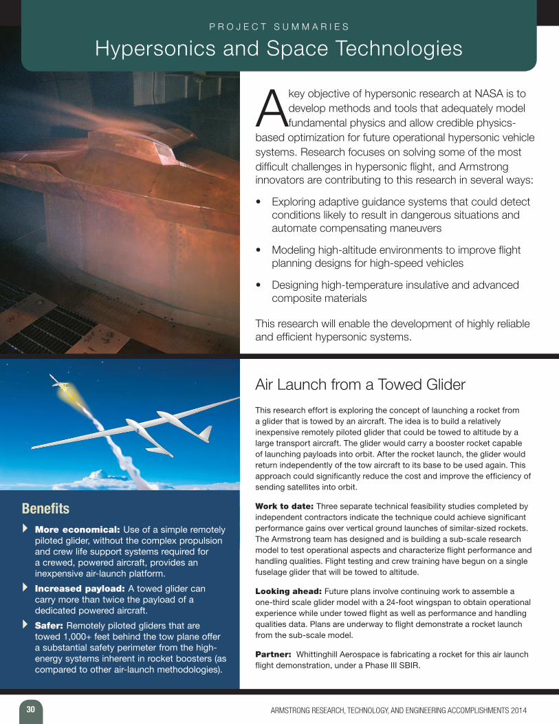
30 ARMSTRONG RESEARCH, TECHNOLOGY, AND ENGINEERING ACCOMPLISHMENTS 2014
P R O J E C T S U M M A R I E S Hypersonics and Space Technologies
A key objective of hypersonic research at NASA is to develop methods and tools that adequately model fundamental physics and allow credible physics-
based optimization for future operational hypersonic vehicle systems. Research focuses on solving some of the most difficult challenges in hypersonic flight, and Armstrong innovators are contributing to this research in several ways:
• Exploring adaptive guidance systems that could detect conditions likely to result in dangerous situations and automate compensating maneuvers
• Modeling high-altitude environments to improve flight planning designs for high-speed vehicles
• Designing high-temperature insulative and advanced composite materials
This research will enable the development of highly reliable and efficient hypersonic systems.
Air Launch from a Towed Glider This research effort is exploring the concept of launching a rocket from a glider that is towed by an aircraft. The idea is to build a relatively inexpensive remotely piloted glider that could be towed to altitude by a large transport aircraft. The glider would carry a booster rocket capable of launching payloads into orbit. After the rocket launch, the glider would return independently of the tow aircraft to its base to be used again. This approach could significantly reduce the cost and improve the efficiency of sending satellites into orbit.
Work to date: Three separate technical feasibility studies completed by independent contractors indicate the technique could achieve significant performance gains over vertical ground launches of similar-sized rockets. The Armstrong team has designed and is building a sub-scale research model to test operational aspects and characterize flight performance and handling qualities. Flight testing and crew training have begun on a single fuselage glider that will be towed to altitude.
Looking ahead: Future plans involve continuing work to assemble a one-third scale glider model with a 24-foot wingspan to obtain operational experience while under towed flight as well as performance and handling qualities data. Plans are underway to flight demonstrate a rocket launch from the sub-scale model.
Partner: Whittinghill Aerospace is fabricating a rocket for this air launch flight demonstration, under a Phase III SBIR.
Benefits } More economical: Use of a simple remotely
piloted glider, without the complex propulsion and crew life support systems required for a crewed, powered aircraft, provides an inexpensive air-launch platform.
} Increased payload: A towed glider can carry more than twice the payload of a dedicated powered aircraft.
} Safer: Remotely piloted gliders that are towed 1,000+ feet behind the tow plane offer a substantial safety perimeter from the high-energy systems inherent in rocket boosters (as compared to other air-launch methodologies).
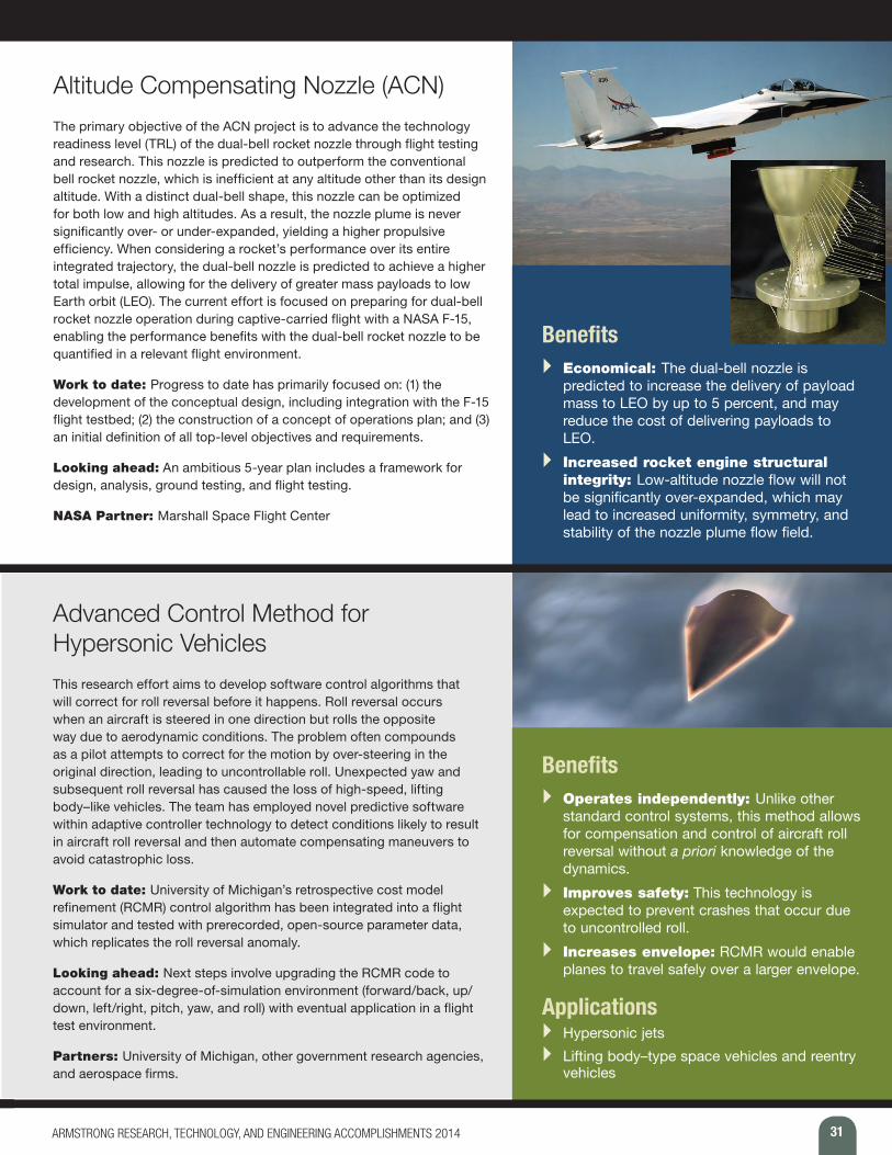
31ARMSTRONG RESEARCH, TECHNOLOGY, AND ENGINEERING ACCOMPLISHMENTS 2014
Altitude Compensating Nozzle (ACN) The primary objective of the ACN project is to advance the technology readiness level (TRL) of the dual-bell rocket nozzle through flight testing and research. This nozzle is predicted to outperform the conventional bell rocket nozzle, which is inefficient at any altitude other than its design altitude. With a distinct dual-bell shape, this nozzle can be optimized for both low and high altitudes. As a result, the nozzle plume is never significantly over- or under-expanded, yielding a higher propulsive efficiency. When considering a rocket’s performance over its entire integrated trajectory, the dual-bell nozzle is predicted to achieve a higher total impulse, allowing for the delivery of greater mass payloads to low Earth orbit (LEO). The current effort is focused on preparing for dual-bell rocket nozzle operation during captive-carried flight with a NASA F-15, enabling the performance benefits with the dual-bell rocket nozzle to be quantified in a relevant flight environment.
Work to date: Progress to date has primarily focused on: (1) the development of the conceptual design, including integration with the F-15 flight testbed; (2) the construction of a concept of operations plan; and (3) an initial definition of all top-level objectives and requirements.
Looking ahead: An ambitious 5-year plan includes a framework for design, analysis, ground testing, and flight testing.
NASA Partner: Marshall Space Flight Center
Benefits } Economical: The dual-bell nozzle is
predicted to increase the delivery of payload mass to LEO by up to 5 percent, and may reduce the cost of delivering payloads to LEO.
} Increased rocket engine structural integrity: Low-altitude nozzle flow will not be significantly over-expanded, which may lead to increased uniformity, symmetry, and stability of the nozzle plume flow field.
Advanced Control Method for Hypersonic VehiclesThis research effort aims to develop software control algorithms that will correct for roll reversal before it happens. Roll reversal occurs when an aircraft is steered in one direction but rolls the opposite way due to aerodynamic conditions. The problem often compounds as a pilot attempts to correct for the motion by over-steering in the original direction, leading to uncontrollable roll. Unexpected yaw and subsequent roll reversal has caused the loss of high-speed, lifting body–like vehicles. The team has employed novel predictive software within adaptive controller technology to detect conditions likely to result in aircraft roll reversal and then automate compensating maneuvers to avoid catastrophic loss.
Work to date: University of Michigan’s retrospective cost model refinement (RCMR) control algorithm has been integrated into a flight simulator and tested with prerecorded, open-source parameter data, which replicates the roll reversal anomaly.
Looking ahead: Next steps involve upgrading the RCMR code to account for a six-degree-of-simulation environment (forward/back, up/down, left/right, pitch, yaw, and roll) with eventual application in a flight test environment.
Partners: University of Michigan, other government research agencies, and aerospace firms.
Benefits } Operates independently: Unlike other
standard control systems, this method allows for compensation and control of aircraft roll reversal without a priori knowledge of the dynamics.
} Improves safety: This technology is expected to prevent crashes that occur due to uncontrolled roll.
} Increases envelope: RCMR would enable planes to travel safely over a larger envelope.
Applications } Hypersonic jets } Lifting body–type space vehicles and reentry
vehicles
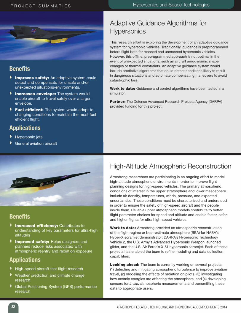
32 ARMSTRONG RESEARCH, TECHNOLOGY, AND ENGINEERING ACCOMPLISHMENTS 2014
P R O J E C T S U M M A R I E S Hypersonics and Space Technologies
Adaptive Guidance Algorithms for Hypersonics This research effort is exploring the development of an adaptive guidance system for hypersonic vehicles. Traditionally, guidance is preprogrammed before flight both for manned and unmanned hypersonic vehicles. However, this offline, preprogrammed approach is not optimal in the event of unexpected situations, such as aircraft aerodynamic shape changes or thermal constraints. An adaptive guidance system would include predictive algorithms that could detect conditions likely to result in dangerous situations and automate compensating maneuvers to avoid catastrophic loss.
Work to date: Guidance and control algorithms have been tested in a simulator.
Partner: The Defense Advanced Research Projects Agency (DARPA) provided funding for this project.
Benefits } Improves safety: An adaptive system could
detect and compensate for unsafe and/or unexpected situations/environments.
} Increases envelope: The system would enable aircraft to travel safely over a larger envelope.
} Fuel efficient: The system would adapt to changing conditions to maintain the most fuel efficient flight.
Applications } Hypersonic jets } General aviation aircraft
High-Altitude Atmospheric ReconstructionArmstrong researchers are participating in an ongoing effort to model high-altitude atmospheric environments in order to improve flight planning designs for high-speed vehicles. The primary atmospheric conditions of interest in the upper stratosphere and lower mesosphere include air density, temperatures, winds, pressure, and expected uncertainties. These conditions must be characterized and understood in order to ensure the safety of high-speed aircraft and the people inside them. Reliable upper atmospheric models contribute to better flight parameter choices for speed and altitude and enable faster, safer, and higher flights for ultra high-speed vehicles.
Work to date: Armstrong provided an atmospheric reconstruction of the flight regime or best-estimate atmosphere (BEA) for NASA’s Hyper-X scramjet demonstrator, DARPA’s Hypersonic Technology Vehicle 2, the U.S. Army’s Advanced Hypersonic Weapon launched glider, and the U.S. Air Force’s X-51 hypersonic scramjet. Each of these projects has enabled the team to refine modeling and data collection capabilities.
Looking ahead: The team is currently working on several projects: (1) detecting and mitigating atmospheric turbulence to improve aviation travel, (2) modeling the effects of radiation on pilots, (3) investigating how cosmic energies are affecting the atmosphere, and (4) developing sensors for in situ atmospheric measurements and transmitting these data to appropriate users.
Benefits } Increased efficiency: Contributes to
understanding of key parameters for ultra-high altitudes
} Improved safety: Helps designers and planners reduce risks associated with atmospheric reentry and radiation exposure
Applications } High-speed aircraft test flight research } Weather prediction and climate change
research } Global Positioning System (GPS) performance
research

33ARMSTRONG RESEARCH, TECHNOLOGY, AND ENGINEERING ACCOMPLISHMENTS 2014
Structurally Integrated Thermal Protection System (SITPS) An Armstrong research team has combined high-temperature insulative and advanced composite materials in a unique design to protect aerospace vehicles from both the high aerodynamic loads as well as high temperatures generated by reentry from space. This dual-purpose sandwich panel design carries both thermal and mechanical loads and increases the operational efficiency of hypersonic vehicle aeroshells. Conventional multi-use hypersonic vehicles typically use non-load-bearing insulation systems to thermally protect the vehicle while using an internal skeleton to bear the mechanical loads. The Armstrong-developed SITPS offers a combined advanced thermal protection system that is both structurally and volumetrically efficient. It uses high-temperature, ceramic-matrix composite and lightweight insulation materials. Incorporating the insulation within a more robust sandwich panel could significantly reduce the operational costs for preparing a vehicle for its next mission.
Work to date: The team developed the materials and process to fabricate a 20x36-inch concept panel for a specific core design and mechanically tested it in a laboratory using three separate methods. The team also has developed a material database of SITPS strength and thermal performance characteristics. In addition, the team examined alternate sandwich core designs to increase the overall thermal and mechanical performance of the concept panels.
Looking ahead: Next steps involve developing panel closeouts and panel-to-panel joints in addition to manufacturing curved SITPS panels.
NASA partners: Langley Research Center and Glenn Research Center
Benefits } Robust: Increases durability of the TPS,
thereby decreasing maintenance time } Strong: Offers higher structural efficiency } Efficient: Permits the reduction of vehicle
mass with its combination of thermal and load-bearing capabilities
Applications } Multi-use hypersonic vehicles } Aircraft exhaust-washed structures
Technicians prepare a Pegasus rocket booster for flight tests with the X-43A “Hypersonic Experimental Vehicle,” or “Hyper-X.”
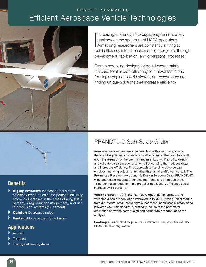
34 ARMSTRONG RESEARCH, TECHNOLOGY, AND ENGINEERING ACCOMPLISHMENTS 2014
P R O J E C T S U M M A R I E S Efficient Aerospace Vehicle Technologies
Increasing efficiency in aerospace systems is a key goal across the spectrum of NASA operations. Armstrong researchers are constantly striving to
build efficiency into all phases of flight projects, through development, fabrication, and operations processes.
From a new wing design that could exponentially increase total aircraft efficiency to a novel test stand for single-engine electric aircraft, our researchers are finding unique solutions that increase efficiency.
PRANDTL-D Sub-Scale Glider Armstrong researchers are experimenting with a new wing shape that could significantly increase aircraft efficiency. The team has built upon the research of the German engineer Ludwig Prandtl to design and validate a scale model of a non-elliptical wing that reduces drag and increases efficiency. The approach to handling adverse yaw employs fine wing adjustments rather than an aircraft’s vertical tail. The Preliminary Research Aerodynamic Design To Lower Drag (PRANDTL-D) wing addresses integrated bending moments and lift to achieve an 11 percent drag reduction. In a propeller application, efficiency could increase by 13 percent.
Work to date: In 2013, the team developed, demonstrated, and validated a scale model of an improved PRANDTL-D wing. Initial results from a 4-month, small-scale flight experiment unequivocally established proverse yaw. Additionally, preliminary results of the parameter estimation show the correct sign and comparable magnitude to the analysis.
Looking ahead: Next steps are to build and test a propeller with the PRANDTL-D configuration.
Benefits } Highly efficient: Increases total aircraft
efficiency by as much as 62 percent, including efficiency increases in the areas of wing (12.5 percent), drag reduction (25 percent), and use in propulsion systems (13 percent)
} Quieter: Decreases noise } Faster: Allows aircraft to fly faster
Applications } Aircraft } Turbines } Energy delivery systems
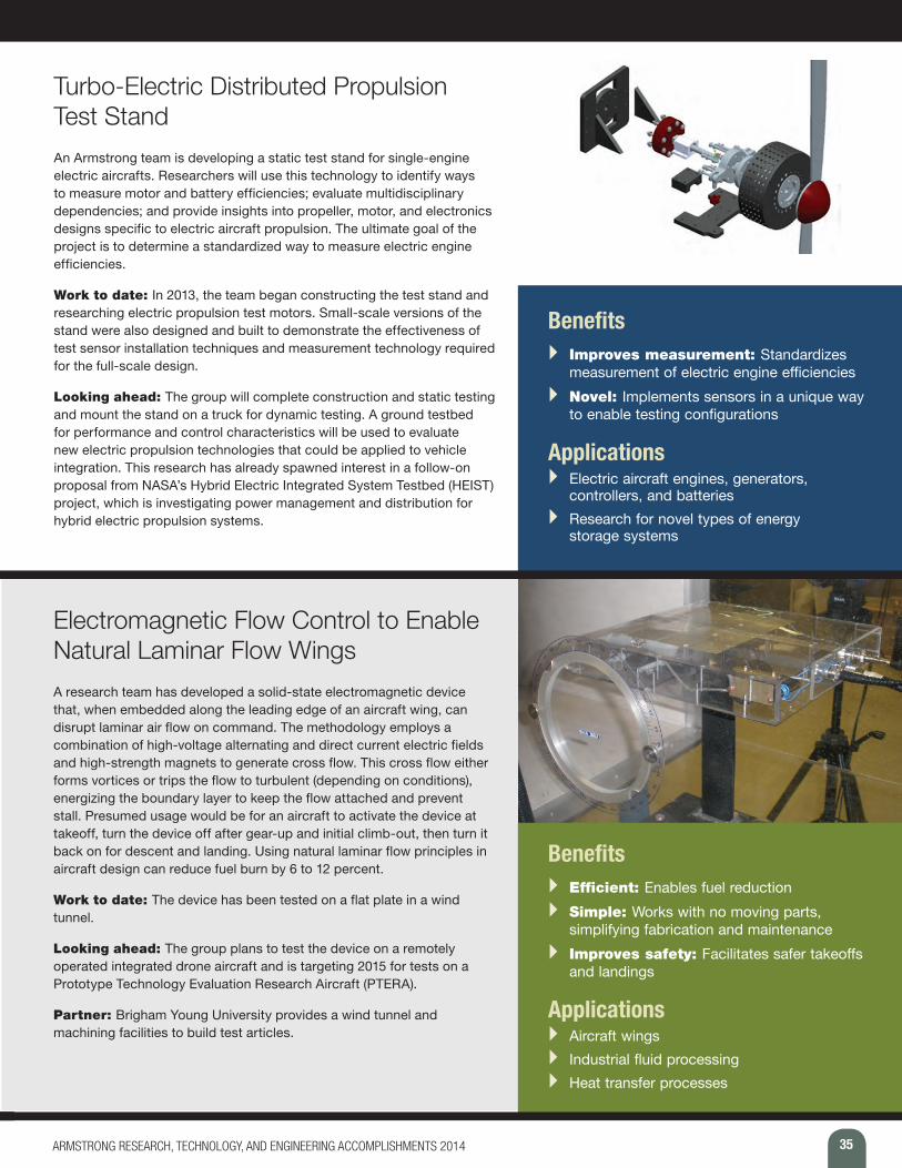
35ARMSTRONG RESEARCH, TECHNOLOGY, AND ENGINEERING ACCOMPLISHMENTS 2014
Turbo-Electric Distributed Propulsion Test Stand An Armstrong team is developing a static test stand for single-engine electric aircrafts. Researchers will use this technology to identify ways to measure motor and battery efficiencies; evaluate multidisciplinary dependencies; and provide insights into propeller, motor, and electronics designs specific to electric aircraft propulsion. The ultimate goal of the project is to determine a standardized way to measure electric engine efficiencies.
Work to date: In 2013, the team began constructing the test stand and researching electric propulsion test motors. Small-scale versions of the stand were also designed and built to demonstrate the effectiveness of test sensor installation techniques and measurement technology required for the full-scale design.
Looking ahead: The group will complete construction and static testing and mount the stand on a truck for dynamic testing. A ground testbed for performance and control characteristics will be used to evaluate new electric propulsion technologies that could be applied to vehicle integration. This research has already spawned interest in a follow-on proposal from NASA’s Hybrid Electric Integrated System Testbed (HEIST) project, which is investigating power management and distribution for hybrid electric propulsion systems.
Benefits } Improves measurement: Standardizes
measurement of electric engine efficiencies } Novel: Implements sensors in a unique way
to enable testing configurations
Applications } Electric aircraft engines, generators,
controllers, and batteries } Research for novel types of energy
storage systems
Electromagnetic Flow Control to Enable Natural Laminar Flow WingsA research team has developed a solid-state electromagnetic device that, when embedded along the leading edge of an aircraft wing, can disrupt laminar air flow on command. The methodology employs a combination of high-voltage alternating and direct current electric fields and high-strength magnets to generate cross flow. This cross flow either forms vortices or trips the flow to turbulent (depending on conditions), energizing the boundary layer to keep the flow attached and prevent stall. Presumed usage would be for an aircraft to activate the device at takeoff, turn the device off after gear-up and initial climb-out, then turn it back on for descent and landing. Using natural laminar flow principles in aircraft design can reduce fuel burn by 6 to 12 percent.
Work to date: The device has been tested on a flat plate in a wind tunnel.
Looking ahead: The group plans to test the device on a remotely operated integrated drone aircraft and is targeting 2015 for tests on a Prototype Technology Evaluation Research Aircraft (PTERA).
Partner: Brigham Young University provides a wind tunnel and machining facilities to build test articles.
Benefits } Efficient: Enables fuel reduction } Simple: Works with no moving parts,
simplifying fabrication and maintenance } Improves safety: Facilitates safer takeoffs
and landings
Applications } Aircraft wings } Industrial fluid processing } Heat transfer processes
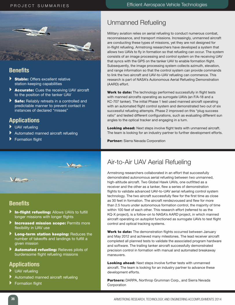
36 ARMSTRONG RESEARCH, TECHNOLOGY, AND ENGINEERING ACCOMPLISHMENTS 2014
P R O J E C T S U M M A R I E S Efficient Aerospace Vehicle Technologies
Unmanned Refueling Military aviation relies on aerial refueling to conduct numerous combat, reconnaissance, and transport missions. Increasingly, unmanned aircraft are conducting these types of missions, yet they are not designed for in-flight refueling. Armstrong researchers have developed a system that allows two UAVs to fly in formation so that refueling can occur. The system consists of an image processing and control system on the receiving UAV that syncs with the GPS on the tanker UAV to enable formation flight. Subsequently, the image processing system collects azimuth, elevation, and range information so that the control system can provide commands to link the two aircraft and UAV-to-UAV refueling can commence. This research is part of NASA’s Autonomous Aerial Refueling Demonstration (AARD) effort.
Work to date: The technology performed successfully in flight tests with manned aircrafts operating as surrogate UAVs (an F/A-18 and a KC-707 tanker). The initial Phase 1 test used manned aircraft operating with an automated flight control system and demonstrated two out of six successful refueling attempts. Phase 2 improved on this “plug success ratio” and tested different configurations, such as evaluating different sun angles to the optical tracker and engaging in a turn.
Looking ahead: Next steps involve flight tests with unmanned aircraft. The team is looking for an industry partner to further development efforts.
Partner: Sierra Nevada Corporation
Benefits } Stable: Offers excellent relative
station-keeping capabilities } Accurate: Cues the receiving UAV aircraft
to the position of the tanker UAV } Safe: Reliably retreats in a controlled and
predictable manner to prevent contact in instances of declared “misses”
Applications } UAV refueling } Automated manned aircraft refueling } Formation flight
Air-to-Air UAV Aerial RefuelingArmstrong researchers collaborated in an effort that successfully demonstrated autonomous aerial refueling between two unmanned, high-altitude aircraft. Two Global Hawk UAVs, one outfitted as a receiver and the other as a tanker, flew a series of demonstration flights to validate advanced UAV-to-UAV aerial refueling control system technology. The two aircraft successfully flew for the first time as close as 30 feet in formation. The aircraft rendezvoused and flew for more than 2.5 hours under autonomous formation control, the majority of time within 100 feet of each other. This research effort (referred to as the KQ-X project), is a follow-on to NASA’s AARD project, in which manned aircraft operating on autopilot functioned as surrogate UAVs to test flight control and optical tracking systems.
Work to date: The demonstration flights occurred between January and May 2012 and achieved many milestones. The lead receiver aircraft completed all planned tests to validate the associated program hardware and software. The trailing tanker aircraft successfully demonstrated precision control in formation with manual and automated breakaway maneuvers.
Looking ahead: Next steps involve further tests with unmanned aircraft. The team is looking for an industry partner to advance these development efforts.
Partners: DARPA, Northrop Grumman Corp., and Sierra Nevada Corporation
Benefits } In-flight refueling: Allows UAVs to fulfill
longer missions with longer flights } Increased mission scope: Permits more
flexibility in UAV use } Long-term station keeping: Reduces the
number of takeoffs and landings to fulfill a given mission
} Automated refueling: Relieves pilots of burdensome flight refueling missions
Applications } UAV refueling } Automated manned aircraft refueling } Formation flight
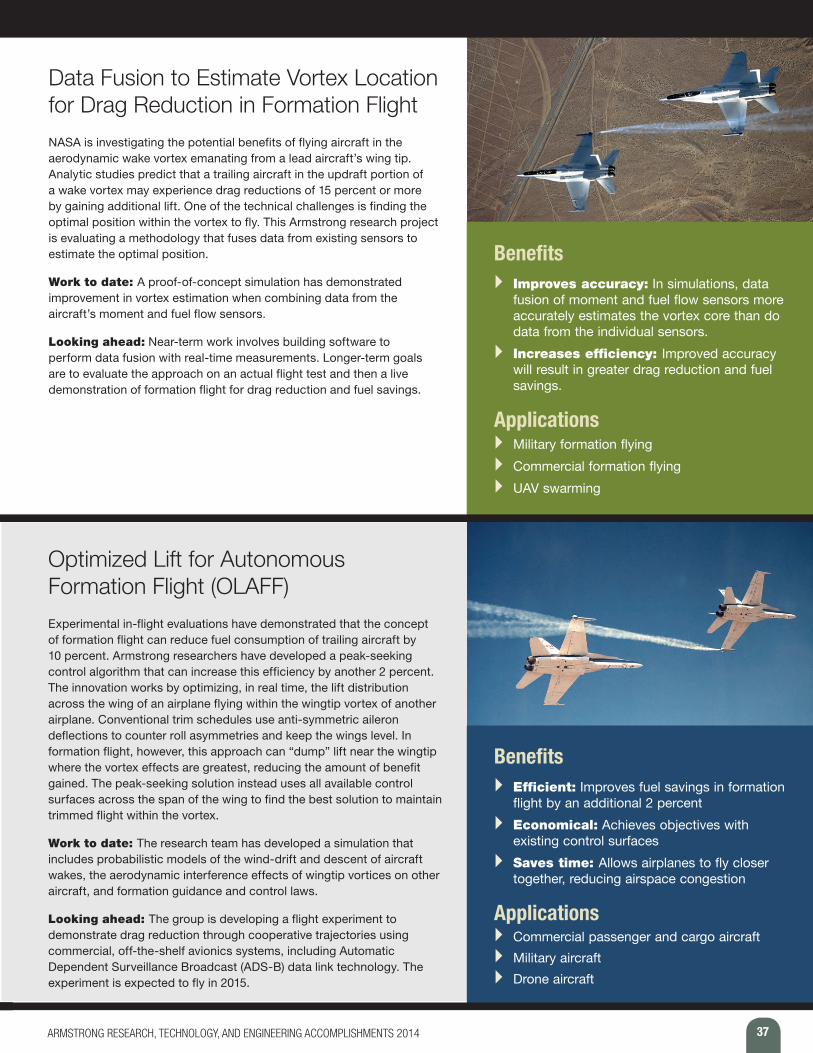
37ARMSTRONG RESEARCH, TECHNOLOGY, AND ENGINEERING ACCOMPLISHMENTS 2014
Data Fusion to Estimate Vortex Location for Drag Reduction in Formation Flight NASA is investigating the potential benefits of flying aircraft in the aerodynamic wake vortex emanating from a lead aircraft’s wing tip. Analytic studies predict that a trailing aircraft in the updraft portion of a wake vortex may experience drag reductions of 15 percent or more by gaining additional lift. One of the technical challenges is finding the optimal position within the vortex to fly. This Armstrong research project is evaluating a methodology that fuses data from existing sensors to estimate the optimal position.
Work to date: A proof-of-concept simulation has demonstrated improvement in vortex estimation when combining data from the aircraft’s moment and fuel flow sensors.
Looking ahead: Near-term work involves building software to perform data fusion with real-time measurements. Longer-term goals are to evaluate the approach on an actual flight test and then a live demonstration of formation flight for drag reduction and fuel savings.
Benefits } Improves accuracy: In simulations, data
fusion of moment and fuel flow sensors more accurately estimates the vortex core than do data from the individual sensors.
} Increases efficiency: Improved accuracy will result in greater drag reduction and fuel savings.
Applications } Military formation flying } Commercial formation flying } UAV swarming
Optimized Lift for Autonomous Formation Flight (OLAFF)Experimental in-flight evaluations have demonstrated that the concept of formation flight can reduce fuel consumption of trailing aircraft by 10 percent. Armstrong researchers have developed a peak-seeking control algorithm that can increase this efficiency by another 2 percent. The innovation works by optimizing, in real time, the lift distribution across the wing of an airplane flying within the wingtip vortex of another airplane. Conventional trim schedules use anti-symmetric aileron deflections to counter roll asymmetries and keep the wings level. In formation flight, however, this approach can “dump” lift near the wingtip where the vortex effects are greatest, reducing the amount of benefit gained. The peak-seeking solution instead uses all available control surfaces across the span of the wing to find the best solution to maintain trimmed flight within the vortex.
Work to date: The research team has developed a simulation that includes probabilistic models of the wind-drift and descent of aircraft wakes, the aerodynamic interference effects of wingtip vortices on other aircraft, and formation guidance and control laws.
Looking ahead: The group is developing a flight experiment to demonstrate drag reduction through cooperative trajectories using commercial, off-the-shelf avionics systems, including Automatic Dependent Surveillance Broadcast (ADS-B) data link technology. The experiment is expected to fly in 2015.
Benefits } Efficient: Improves fuel savings in formation
flight by an additional 2 percent } Economical: Achieves objectives with
existing control surfaces } Saves time: Allows airplanes to fly closer
together, reducing airspace congestion
Applications } Commercial passenger and cargo aircraft } Military aircraft } Drone aircraft
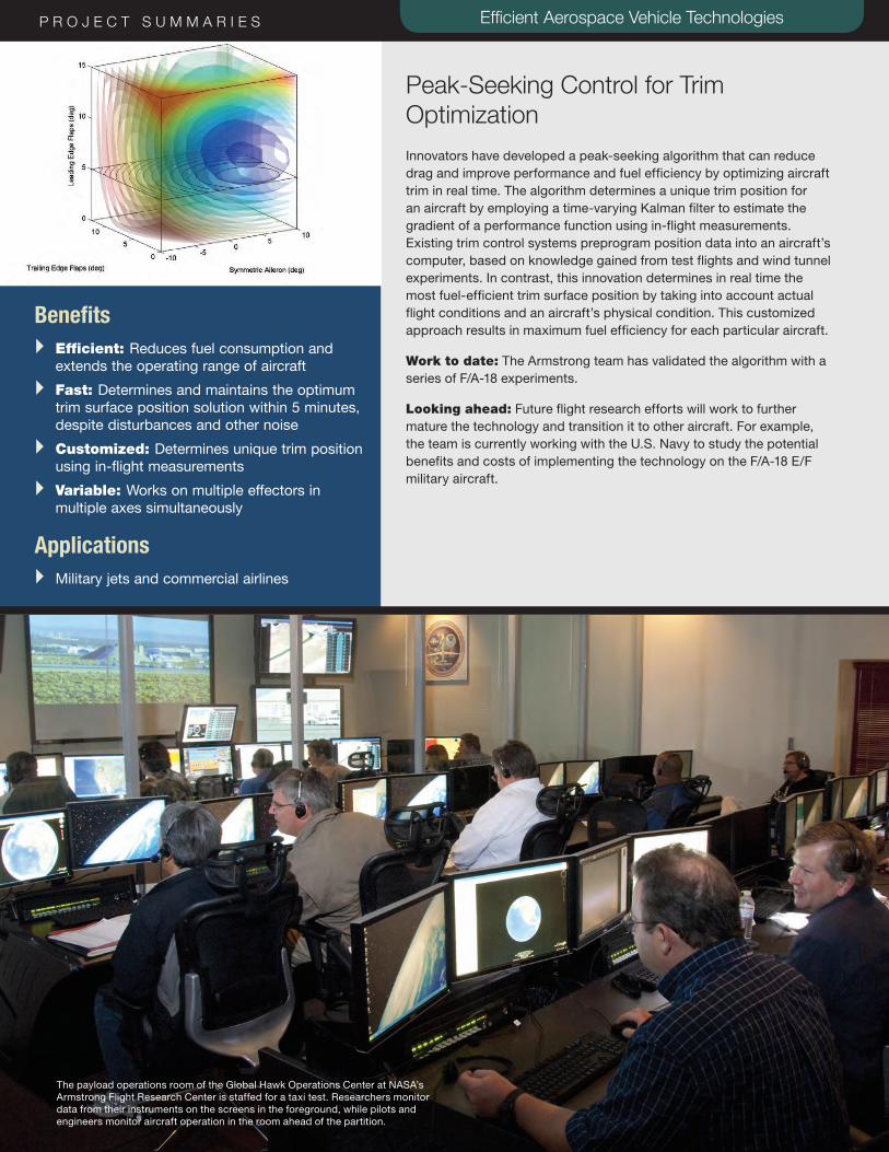
38 ARMSTRONG RESEARCH, TECHNOLOGY, AND ENGINEERING ACCOMPLISHMENTS 2014
P R O J E C T S U M M A R I E S Efficient Aerospace Vehicle TechnologiesP R O J E C T S U M M A R I E S Efficient Aerospace Vehicle Technologies
Peak-Seeking Control for Trim Optimization Innovators have developed a peak-seeking algorithm that can reduce drag and improve performance and fuel efficiency by optimizing aircraft trim in real time. The algorithm determines a unique trim position for an aircraft by employing a time-varying Kalman filter to estimate the gradient of a performance function using in-flight measurements. Existing trim control systems preprogram position data into an aircraft’s computer, based on knowledge gained from test flights and wind tunnel experiments. In contrast, this innovation determines in real time the most fuel-efficient trim surface position by taking into account actual flight conditions and an aircraft’s physical condition. This customized approach results in maximum fuel efficiency for each particular aircraft.
Work to date: The Armstrong team has validated the algorithm with a series of F/A-18 experiments.
Looking ahead: Future flight research efforts will work to further mature the technology and transition it to other aircraft. For example, the team is currently working with the U.S. Navy to study the potential benefits and costs of implementing the technology on the F/A-18 E/F military aircraft.
Benefits } Efficient: Reduces fuel consumption and
extends the operating range of aircraft } Fast: Determines and maintains the optimum
trim surface position solution within 5 minutes, despite disturbances and other noise
} Customized: Determines unique trim position using in-flight measurements
} Variable: Works on multiple effectors in multiple axes simultaneously
Applications } Military jets and commercial airlines
The payload operations room of the Global Hawk Operations Center at NASA’s Armstrong Flight Research Center is staffed for a taxi test. Researchers monitor data from their instruments on the screens in the foreground, while pilots and engineers monitor aircraft operation in the room ahead of the partition.
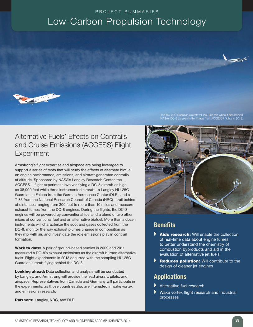
39ARMSTRONG RESEARCH, TECHNOLOGY, AND ENGINEERING ACCOMPLISHMENTS 2014
P R O J E C T S U M M A R I E S Low-Carbon Propulsion Technology
The HU-25C Guardian aircraft will look like this when it flies behind NASA’s DC-8 as seen in this image from ACCESS I flights in 2013.
Alternative Fuels’ Effects on Contrails and Cruise Emissions (ACCESS) Flight ExperimentArmstrong’s flight expertise and airspace are being leveraged to support a series of tests that will study the effects of alternate biofuel on engine performance, emissions, and aircraft-generated contrails at altitude. Sponsored by NASA’s Langley Research Center, the ACCESS-II flight experiment involves flying a DC-8 aircraft as high as 38,000 feet while three instrumented aircraft—a Langley HU-25C Guardian, a Falcon from the German Aerospace Center (DLR), and a T-33 from the National Research Council of Canada (NRC)—trail behind at distances ranging from 300 feet to more than 10 miles and measure exhaust fumes from the DC-8 engines. During the flights, the DC-8 engines will be powered by conventional fuel and a blend of two other mixes of conventional fuel and an alternative biofuel. More than a dozen instruments will characterize the soot and gases collected from the DC-8, monitor the way exhaust plumes change in composition as they mix with air, and investigate the role emissions play in contrail formation.
Work to date: A pair of ground-based studies in 2009 and 2011 measured a DC-8’s exhaust emissions as the aircraft burned alternative fuels. Flight experiments in 2013 occurred with the sampling HU-25C Guardian aircraft flying behind the DC-8.
Looking ahead: Data collection and analysis will be conducted by Langley, and Armstrong will provide the lead aircraft, pilots, and airspace. Representatives from Canada and Germany will participate in the experiments, as those countries also are interested in wake vortex and emissions research.
Partners: Langley, NRC, and DLR
Benefits } Aids research: Will enable the collection
of real-time data about engine fumes to better understand the chemistry of combustion byproducts and aid in the evaluation of alternative jet fuels
} Reduces pollution: Will contribute to the design of cleaner jet engines
Applications } Alternative fuel research } Wake vortex flight research and industrial
processes
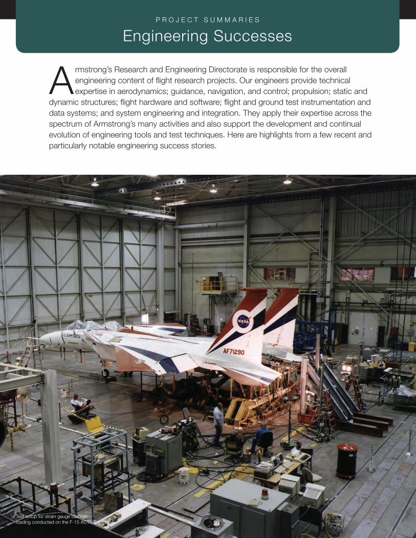
40 ARMSTRONG RESEARCH, TECHNOLOGY, AND ENGINEERING ACCOMPLISHMENTS 2014
P R O J E C T S U M M A R I E S Engineering Successes
Armstrong’s Research and Engineering Directorate is responsible for the overall engineering content of flight research projects. Our engineers provide technical expertise in aerodynamics; guidance, navigation, and control; propulsion; static and
dynamic structures; flight hardware and software; flight and ground test instrumentation and data systems; and system engineering and integration. They apply their expertise across the spectrum of Armstrong’s many activities and also support the development and continual evolution of engineering tools and test techniques. Here are highlights from a few recent and particularly notable engineering success stories.
Test setup for strain gauge calibration loading conducted on the F-15 ACTIVE.

41ARMSTRONG RESEARCH, TECHNOLOGY, AND ENGINEERING ACCOMPLISHMENTS 2014
“
Dope on a Rope 2: Development of a Dream Chaser Aero Tow Simulation Armstrong innovators have developed a lifting-body aero tow simulation to determine feasibility and procedures for towing the Dream Chaser Flight Test Vehicle (FTV) to an altitude of 30,000 feet. The Dream Chaser FTV is a full-scale, full-weight, single-seat, manned glide test spacecraft and was designed to conduct approach and landing tests. The aero tow concept calls for a large transport-size jet aircraft to tow a piloted commercial re-entry vehicle into the air with a long robust towline. At a predetermined altitude, the re-entry vehicle separates from the tow aircraft and is landed by the astronaut on board. The tow concept was successfully demonstrated in the late 1990s in the Eclipse Project with F-106 and C-141 aircraft.
“Dope on a Rope” was the unofficial Eclipse Project name, a moniker developed in jest to teasingly poke fun at the intelligence of the project pilot. The name stuck, and “Dope on a Rope 2” has been adopted as the unofficial project name for the follow-on work.
Work to date: The Armstrong team linked an existing simulation of the HL-20 lifting-body aircraft and a C-17 to determine feasibility. The simulation has been updated with models of the Dream Chaser FTV, and a cockpit with representative windows has been built. The simulation is now being used to develop tow profiles and procedures, evaluate control law changes, and determine potential tow vehicles. It is also being used to validate the rope model for stability and control analysis.
Looking ahead: An important role of the simulator is to evaluate different aircraft as Dream Chaser tow planes. Simulations of potential tow aircraft can be linked to evaluate performance and tow efficiency. When a tow aircraft is selected, the simulation will be used to develop tow techniques and procedures.
Partners: Sierra Nevada Corporation and U.S. Air Force
As a result of evaluations in the Aero Tow Simulator, Sierra Nevada Corporation has made Aero Tow the primary method of getting the Dream Chaser FTV to altitude for the approach and landing testing to be performed in 2015-2016. The Aero Tow Simulator will play a vital role in developing towing techniques and procedures, tow mode flight control development, and astronaut training.
Bruce Cogan, PI ”
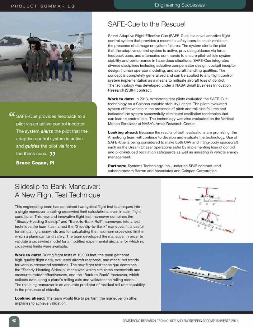
42 ARMSTRONG RESEARCH, TECHNOLOGY, AND ENGINEERING ACCOMPLISHMENTS 2014
P R O J E C T S U M M A R I E S
“
Engineering Successes
SAFE-Cue to the Rescue! Smart Adaptive Flight Effective Cue (SAFE-Cue) is a novel adaptive flight control system that provides a means to safely operate an air vehicle in the presence of damage or system failures. The system alerts the pilot that the adaptive control system is active, provides guidance via force feedback cues, and attenuates commands to ensure pilot-vehicle system stability and performance in hazardous situations. SAFE-Cue integrates diverse disciplines including adaptive compensator design, cockpit inceptor design, human operator modeling, and aircraft handling qualities. The concept is completely generalized and can be applied to any flight control system implementation as a means to mitigate aircraft loss of control. The technology was developed under a NASA Small Business Innovation Research (SBIR) contract.
Work to date: In 2013, Armstrong test pilots evaluated the SAFE-Cue technology on a Calspan variable stability Learjet. The pilots evaluated system effectiveness in the presence of pitch and roll axis failures and indicated the system successfully eliminated oscillation tendencies that can lead to control loss. The technology was also evaluated on the Vertical Motion Simulator at NASA’s Ames Research Center.
Looking ahead: Because the results of both evaluations are promising, the Armstrong team will continue to develop and evaluate the technology. Use of SAFE-Cue is being considered to make both UAV and lifting-body spacecraft such as the Dream Chaser operations safer by implementing loss of control and pilot-induced oscillation safeguards as well as assisting in vehicle energy management.
Partners: Systems Technology, Inc., under an SBIR contract, and subcontractors Barron and Associates and Calspan Corporation
SAFE-Cue provides feedback to a
pilot via an active control inceptor.
The system alerts the pilot that the
adaptive control system is active
and guides the pilot via force
feedback cues.
Bruce Cogan, PI”
Slideslip-to-Bank Maneuver: A New Flight Test Technique This engineering team has combined two typical flight test techniques into a single maneuver enabling crosswind limit calculations, even in calm flight conditions. This new and innovative flight test maneuver combines the “Steady-Heading Sideslip” and “Bank-to-Bank Roll” maneuvers into a test technique the team has named the “Slideslip-to-Bank” maneuver. It is useful for simulating crosswinds and for calculating the maximum crosswind limit in which a plane can land safely. The team developed the maneuver in order to validate a crosswind model for a modified experimental airplane for which no crosswind limits were available.
Work to date: During flight tests at 10,000 feet, the team gathered high-quality flight data, evaluated aircraft response, and measured trends for various crosswind scenarios. The new flight test technique combines the “Steady-Heading Sideslip” maneuver, which simulates crosswinds and measures rudder effectiveness, and the “Bank-to-Bank” maneuver, which collects data along a plane’s rolling axis and validates the rolling model. The resulting maneuver is an accurate predictor of residual roll rate capability in the presence of sideslip.
Looking ahead: The team would like to perform the maneuver on other airplanes to achieve validation.

43ARMSTRONG RESEARCH, TECHNOLOGY, AND ENGINEERING ACCOMPLISHMENTS 2014
PTERA System Identification Flight TestsA technology gap exists between well-controlled wind tunnel tests that only examine aerodynamics and full-scale flight testing where most systems integration issues surface. The Prototype Technology Evaluation Research Aircraft (PTERA) is a highly reconfigurable unmanned flight research testbed that bridges the gap between wind tunnel and manned flight testing with low-cost, low-risk, flight-based evaluation of high-risk technologies. PTERA allows for evaluation of numerous advanced aerodynamic configurations, research control laws, circulation control systems. Non-structural and replaceable leading/trailing edge flaps permit flight evaluation of various research high lift and drag reduction technologies. Any UAV autopilot and flight control computer can be integrated into the platform.
All PTERA data and models are open source and available to the entire flight research community. There are no publication restrictions on flight test results and no aircraft proprietary data.
Work to date: PTERA flew for the first time in July 2012, and the focus was on system testing, pilot familiarization, and initial performance measurements. In 2013, PTERA flew an additional six flights. Primary focus was on system identification to develop aero models and to evaluate stall characteristics. Tao sensors were also flown on these flights as part of a NASA Aeronautics Research Mission Directorate Seedling Fund research effort.
Looking ahead: A PTERA aircraft will arrive at Armstrong in fall 2014. Several flight research experiments have already been identified.
Partner: Area-I, Inc., developed the PTERA testbed under the NASA SBIR program. Other partners include the State of Georgia, Georgia Tech Research Institute, Middle Georgia State College, Solid Concepts, and Aeroprobe Corporation.
“
”
This research platform provides an
affordable bridge between wind tunnel
and full-scale testing to mature new
aircraft technologies through flight test
and evaluation.
Bruce Cogan, PI
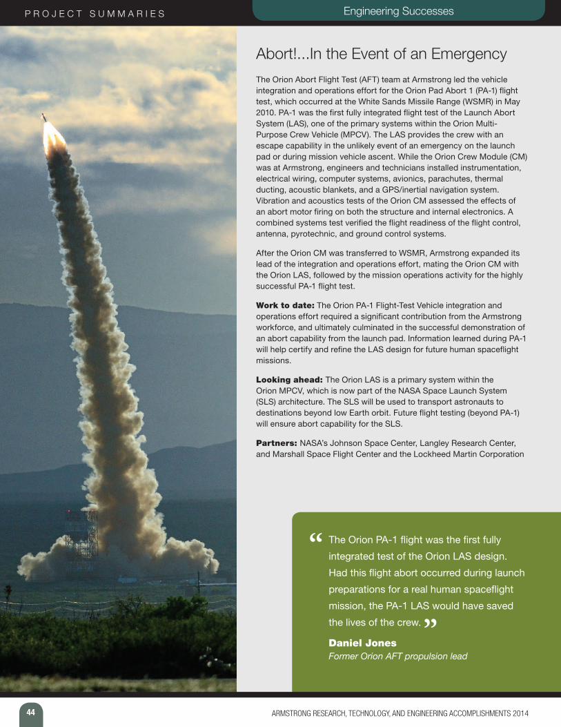
44 ARMSTRONG RESEARCH, TECHNOLOGY, AND ENGINEERING ACCOMPLISHMENTS 2014
P R O J E C T S U M M A R I E S Engineering Successes
Abort!...In the Event of an EmergencyThe Orion Abort Flight Test (AFT) team at Armstrong led the vehicle integration and operations effort for the Orion Pad Abort 1 (PA-1) flight test, which occurred at the White Sands Missile Range (WSMR) in May 2010. PA-1 was the first fully integrated flight test of the Launch Abort System (LAS), one of the primary systems within the Orion Multi-Purpose Crew Vehicle (MPCV). The LAS provides the crew with an escape capability in the unlikely event of an emergency on the launch pad or during mission vehicle ascent. While the Orion Crew Module (CM) was at Armstrong, engineers and technicians installed instrumentation, electrical wiring, computer systems, avionics, parachutes, thermal ducting, acoustic blankets, and a GPS/inertial navigation system. Vibration and acoustics tests of the Orion CM assessed the effects of an abort motor firing on both the structure and internal electronics. A combined systems test verified the flight readiness of the flight control, antenna, pyrotechnic, and ground control systems.
After the Orion CM was transferred to WSMR, Armstrong expanded its lead of the integration and operations effort, mating the Orion CM with the Orion LAS, followed by the mission operations activity for the highly successful PA-1 flight test.
Work to date: The Orion PA-1 Flight-Test Vehicle integration and operations effort required a significant contribution from the Armstrong workforce, and ultimately culminated in the successful demonstration of an abort capability from the launch pad. Information learned during PA-1 will help certify and refine the LAS design for future human spaceflight missions.
Looking ahead: The Orion LAS is a primary system within the Orion MPCV, which is now part of the NASA Space Launch System (SLS) architecture. The SLS will be used to transport astronauts to destinations beyond low Earth orbit. Future flight testing (beyond PA-1) will ensure abort capability for the SLS.
Partners: NASA’s Johnson Space Center, Langley Research Center, and Marshall Space Flight Center and the Lockheed Martin Corporation
“ The Orion PA-1 flight was the first fully
integrated test of the Orion LAS design.
Had this flight abort occurred during launch
preparations for a real human spaceflight
mission, the PA-1 LAS would have saved
the lives of the crew.
Daniel JonesFormer Orion AFT propulsion lead
”
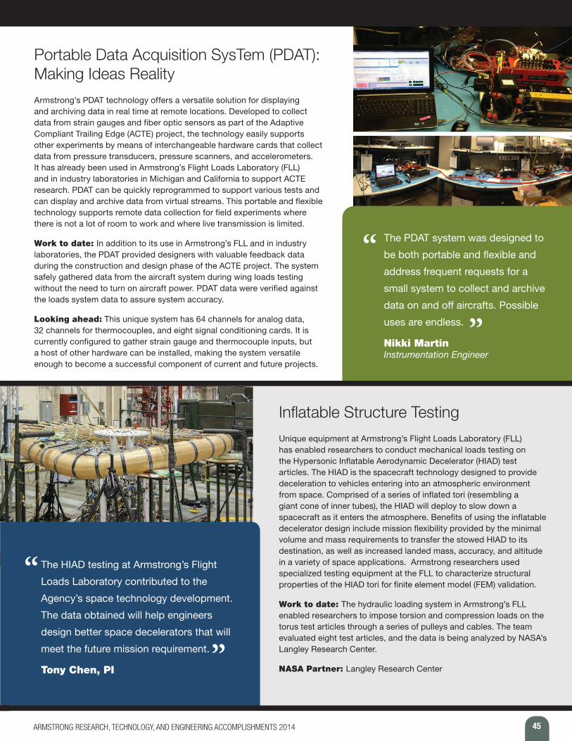
45ARMSTRONG RESEARCH, TECHNOLOGY, AND ENGINEERING ACCOMPLISHMENTS 2014
Portable Data Acquisition SysTem (PDAT): Making Ideas Reality Armstrong’s PDAT technology offers a versatile solution for displaying and archiving data in real time at remote locations. Developed to collect data from strain gauges and fiber optic sensors as part of the Adaptive Compliant Trailing Edge (ACTE) project, the technology easily supports other experiments by means of interchangeable hardware cards that collect data from pressure transducers, pressure scanners, and accelerometers. It has already been used in Armstrong’s Flight Loads Laboratory (FLL) and in industry laboratories in Michigan and California to support ACTE research. PDAT can be quickly reprogrammed to support various tests and can display and archive data from virtual streams. This portable and flexible technology supports remote data collection for field experiments where there is not a lot of room to work and where live transmission is limited.
Work to date: In addition to its use in Armstrong’s FLL and in industry laboratories, the PDAT provided designers with valuable feedback data during the construction and design phase of the ACTE project. The system safely gathered data from the aircraft system during wing loads testing without the need to turn on aircraft power. PDAT data were verified against the loads system data to assure system accuracy.
Looking ahead: This unique system has 64 channels for analog data, 32 channels for thermocouples, and eight signal conditioning cards. It is currently configured to gather strain gauge and thermocouple inputs, but a host of other hardware can be installed, making the system versatile enough to become a successful component of current and future projects.
“ The PDAT system was designed to
be both portable and flexible and
address frequent requests for a
small system to collect and archive
data on and off aircrafts. Possible
uses are endless.
Nikki Martin Instrumentation Engineer
”
Inflatable Structure TestingUnique equipment at Armstrong’s Flight Loads Laboratory (FLL) has enabled researchers to conduct mechanical loads testing on the Hypersonic Inflatable Aerodynamic Decelerator (HIAD) test articles. The HIAD is the spacecraft technology designed to provide deceleration to vehicles entering into an atmospheric environment from space. Comprised of a series of inflated tori (resembling a giant cone of inner tubes), the HIAD will deploy to slow down a spacecraft as it enters the atmosphere. Benefits of using the inflatable decelerator design include mission flexibility provided by the minimal volume and mass requirements to transfer the stowed HIAD to its destination, as well as increased landed mass, accuracy, and altitude in a variety of space applications. Armstrong researchers used specialized testing equipment at the FLL to characterize structural properties of the HIAD tori for finite element model (FEM) validation.
Work to date: The hydraulic loading system in Armstrong’s FLL enabled researchers to impose torsion and compression loads on the torus test articles through a series of pulleys and cables. The team evaluated eight test articles, and the data is being analyzed by NASA’s Langley Research Center.
NASA Partner: Langley Research Center
“
”
The HIAD testing at Armstrong’s Flight
Loads Laboratory contributed to the
Agency’s space technology development.
The data obtained will help engineers
design better space decelerators that will
meet the future mission requirement.
Tony Chen, PI
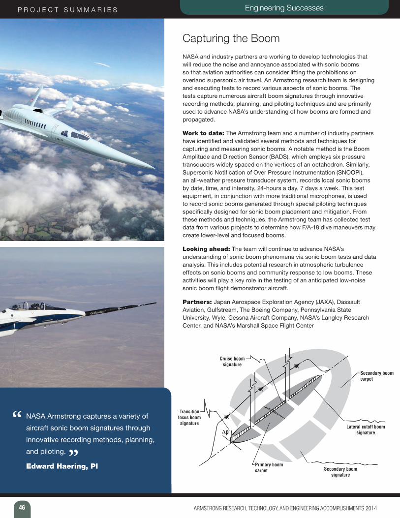
46 ARMSTRONG RESEARCH, TECHNOLOGY, AND ENGINEERING ACCOMPLISHMENTS 2014
P R O J E C T S U M M A R I E S Engineering Successes
Capturing the BoomNASA and industry partners are working to develop technologies that will reduce the noise and annoyance associated with sonic booms so that aviation authorities can consider lifting the prohibitions on overland supersonic air travel. An Armstrong research team is designing and executing tests to record various aspects of sonic booms. The tests capture numerous aircraft boom signatures through innovative recording methods, planning, and piloting techniques and are primarily used to advance NASA’s understanding of how booms are formed and propagated.
Work to date: The Armstrong team and a number of industry partners have identified and validated several methods and techniques for capturing and measuring sonic booms. A notable method is the Boom Amplitude and Direction Sensor (BADS), which employs six pressure transducers widely spaced on the vertices of an octahedron. Similarly, Supersonic Notification of Over Pressure Instrumentation (SNOOPI), an all-weather pressure transducer system, records local sonic booms by date, time, and intensity, 24-hours a day, 7 days a week. This test equipment, in conjunction with more traditional microphones, is used to record sonic booms generated through special piloting techniques specifically designed for sonic boom placement and mitigation. From these methods and techniques, the Armstrong team has collected test data from various projects to determine how F/A-18 dive maneuvers may create lower-level and focused booms.
Looking ahead: The team will continue to advance NASA’s understanding of sonic boom phenomena via sonic boom tests and data analysis. This includes potential research in atmospheric turbulence effects on sonic booms and community response to low booms. These activities will play a key role in the testing of an anticipated low-noise sonic boom flight demonstrator aircraft.
Partners: Japan Aerospace Exploration Agency (JAXA), Dassault Aviation, Gulfstream, The Boeing Company, Pennsylvania State University, Wyle, Cessna Aircraft Company, NASA’s Langley Research Center, and NASA’s Marshall Space Flight Center
“ NASA Armstrong captures a variety of
aircraft sonic boom signatures through
innovative recording methods, planning,
and piloting.
Edward Haering, PI”

47ARMSTRONG RESEARCH, TECHNOLOGY, AND ENGINEERING ACCOMPLISHMENTS 2014
Flying an Airplane Like a Rocket NASA Armstrong’s high-performance F/A-18 Full-Scale Advanced Systems Testbed (FAST) aircraft was key to helping test and validate the effectiveness of innovative self-adaptive software being considered for use in the next-generation Space Launch System (SLS). Developed by engineers at Marshall Space Flight Center, the SLS rocket will be NASA’s largest and most powerful launch vehicle for deep space missions. The adaptive software is designed to make real-time adjustments as a vehicle pushes toward space, helping to improve rocket performance and enhance crew safety in the particularly stressful launch portions of flight. The team installed SLS flight control software onto research computers aboard the FAST aircraft and simulated a rocket in its early flight phase to test the adaptive control software. The FAST aircraft’s high performance allowed it to fly a trajectory that was dynamically similar to a rocket launch. This collaborative project yielded a major advance in launch vehicle flight control technology and substantially accelerated the application of adaptive control to manned systems.
Work to date: Flight tests occurred at Armstrong in late 2013. During these flights, almost 100 SLS trajectories and over a dozen straight-and-level airframe structural amplification tests were successfully executed, many of which focused on collecting additional data regarding the interaction of the pilot, the simulated SLS vehicle dynamics, and the adaptive augmenting control algorithm.
Looking ahead: The team is analyzing flight data and considering ways to apply similar technology to aircraft and atmospheric re-entry vehicles.
NASA Partners: Marshall Space Flight Center and NASA Engineering and Safety Center
The goal of the F/A-18 flights was to
advance the technology readiness of the
SLS adaptive control design by operating
it in a relevant environment while intro-
ducing a wide variety of unusual launch
scenarios. Test pilots also exercised the
SLS controller’s manual steering mode,
providing valuable feedback on its design
and performance.
Curtis Hanson, PI
“
”
Masking the Sun and Scoping the ProblemInnovative hardware upgrades to Armstrong’s Airborne Schlieren Imaging System (ASIS) are improving reliability and precision. The ASIS platform captures shockwave images by aligning a supersonic aircraft between a camera-equipped aircraft and the sun, and then watching as the shocks put an apparent ripple on the sun’s edge. The technique enables researchers to validate data from supersonic models and wind tunnel tests. Armstrong engineers recently designed and implemented adjustments to the ASIS Forward-Looking Infrared (FLIR) camera pod to improve its performance.
Work to date: Innovators developed highly precise solar masks that block all but the very edge of the sun. Since the apparent solar radius changes throughout the year due to Earth’s changing proximity to the sun, the team created two masks that are 0.001 inches different in radius—one for a summer mean radius and another for a winter mean. A programmable tooling machine made manufacturing the masks straightforward; the harder challenge was inspecting them. The team employed a laser projection device to create well-defined and accurately enlarged mask images, enabling small radial measurements. The group also used borescopes to view a “blind” connector that did not fully mate during pod assembly, causing routine flight vibrations to induce intermittent system failures. A new connector scheme allows for a more robust and fully mated connection.
Looking ahead: The team will continue to test and mature the technology and to identify potential research partners.
Armstrong has the tools, ingenu-
ity, and skills on hand to tackle
difficult problems. The ASIS team
made full use of these skills when
developing and improving the
system. We look forward to
obtaining elusive aircraft shock
visuals with this equipment.
Paul Bean, PI
“
”
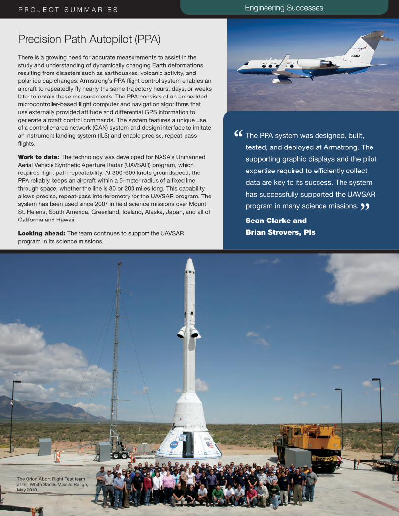
48 ARMSTRONG RESEARCH, TECHNOLOGY, AND ENGINEERING ACCOMPLISHMENTS 2014
“
”
P R O J E C T S U M M A R I E S Engineering Successes
Precision Path Autopilot (PPA) There is a growing need for accurate measurements to assist in the study and understanding of dynamically changing Earth deformations resulting from disasters such as earthquakes, volcanic activity, and polar ice cap changes. Armstrong’s PPA flight control system enables an aircraft to repeatedly fly nearly the same trajectory hours, days, or weeks later to obtain these measurements. The PPA consists of an embedded microcontroller-based flight computer and navigation algorithms that use externally provided attitude and differential GPS information to generate aircraft control commands. The system features a unique use of a controller area network (CAN) system and design interface to imitate an instrument landing system (ILS) and enable precise, repeat-pass flights.
Work to date: The technology was developed for NASA’s Unmanned Aerial Vehicle Synthetic Aperture Radar (UAVSAR) program, which requires flight path repeatability. At 300-600 knots groundspeed, the PPA reliably keeps an aircraft within a 5-meter radius of a fixed line through space, whether the line is 30 or 200 miles long. This capability allows precise, repeat-pass interferometry for the UAVSAR program. The system has been used since 2007 in field science missions over Mount St. Helens, South America, Greenland, Iceland, Alaska, Japan, and all of California and Hawaii.
Looking ahead: The team continues to support the UAVSAR program in its science missions.
The PPA system was designed, built,
tested, and deployed at Armstrong. The
supporting graphic displays and the pilot
expertise required to efficiently collect
data are key to its success. The system
has successfully supported the UAVSAR
program in many science missions.
Sean Clarke and
Brian Strovers, PIs
The Orion Abort Flight Test team at the White Sands Missile Range, May 2010.

49ARMSTRONG RESEARCH, TECHNOLOGY, AND ENGINEERING ACCOMPLISHMENTS 2014
AppendixHyperelastic Research/Lightweight Flexible Aircraft
Adaptive Compliant Trailing Edge (ACTE) Flight ExperimentEthan Baumann 661-276-3417 | [email protected]
Fundamental Hyperelastic Material StudyEric Miller 661-276-7041 | [email protected]
Additional Information:
} Streett, C. L.; Casper, J. H.; Lockard, D. P.; Khorrami, M. R.; Stoker, R.W.; Elkoby, R.; Wenneman W. F.; Underbrink, J. R.; “Aerodynamic Noise Reduction for High-Lift Devices on a Swept Wing Model,” 44th AIAA Aerospace Science Meeting and Exhibit, Reno Nevada, AIAA 2006-212, 2006.
X-56A Multi-Utility Technology Testbed (MUTT) John Bosworth 661-276-3792 | [email protected]
Robust Virtual Deformation Control of the X-56A Model Peter Suh 661-276-3402 | [email protected]
Real-Time Structural Overload Control via Control Allocation OptimizationChris Miller 661-276-2902 | [email protected]
Inverse Finite Element Method (iFEM) Investigation for Adaptive StructuresEric Miller 661-276-7041 | [email protected]
Active Control of Tailored LaminatesChris Kostyk 661-276-5443 | [email protected]
Active/Adaptive Flexible Motion Controls with Aeroservoelastic System UncertaintiesChan-gi Pak 661-276-5698 | [email protected]
Flight and Ground Experimental Test Technologies
Real-Time Parameter IdentificationMark Smith 661-276-3177 | [email protected]
Vehicle Integrated Propulsion Research (VIPR)Clinton St. John 661-276-5306 | [email protected]
Dynamic Inertia Measurement Method Alex Chin 661-276-2681 | [email protected]
Additional Information:
} Witter, M.C., “Rigid Body Inertia Property Estimation Using the Dynamic Inertia Method,” Master’s Thesis, University of Cincinnati, 2000.
} Lazor, D.R., “Considerations for Using the Dynamic Inertia Method in Estimating Rigid Body Inertia Property,” Master’s Thesis, University of Cincinnati, 2004.
} ATA Engineering, Inc., “Final Report on Dynamic Inertia Measurement Method Testing,” ATA Report No. 57205, November 17, 2010.
Acoustic Diagnostics for Turbofan Health MonitoringDevin Boyle 661-276-2443 | [email protected]
Hot Ground Vibration TestsLarry Hudson 661-276-3925 | [email protected]
Verification and Validation (V&V) Bench EnhancementsCJ Bixby 661-276-3394 | [email protected]
Fiber Optic Sensing
Compact FOSS (cFOSS)Allen Parker 661-276-2407 | [email protected]

50 ARMSTRONG RESEARCH, TECHNOLOGY, AND ENGINEERING ACCOMPLISHMENTS 2014
Additional Information:
} NASA has three patents issued for this technology portfolio (U.S. Patent 7,715,994, U.S. Patent 7,520,176, and U.S. Patent 8,700,358).
} Emmons, Michael C.; Sunny Karnani; Stefano Trono; Kotekar P. Mohanchandra; W. Lance Richards; and Gregory P. Carman; (2010) “Strain Measurement Validation of Embedded Fiber Bragg Gratings,” International Journal of Optomechatronics, 4:1, 22-33.
} Mohanchandra, K.P.; S. Karnani; M.C. Emmons; W.L. Richards; and G.P. Carman; “Thin Film NiTi Coatings on Optical Fiber Bragg Sensors,” Applied Physics Letters 93 03194 (2008).
Hybrid FOSS (HyFOSS)Allen Parker 661-276-2407 | [email protected]
Patrick Chan 661-276-6170 | [email protected]
Smart Sensing Using WaveletsPhilip Hamory 661-276-3090 | [email protected]
Determining Applied Load Data with Strain MeasurementsLance Richards 661-276-3562 | [email protected]
Strain Sensing for Displacement and Two-Dimensional (2D) ShapeLance Richards 661-276-3562 | [email protected]
Cryogenic FOSS (CryoFOSS)Allen Parker 661-276-2407 | [email protected]
High-Temperature Strain SensingAnthony Piazza 661-276-2714 | [email protected]
Strain Sensing for Highly Elastic MaterialsAnthony Piazza 661-276-2714 | [email protected]
Health Monitoring of Flight StructuresLarry Hudson 661-276-3925 | [email protected]
Supersonic Flight Research
Sonic Boom Measurement TechniquesLarry Cliatt 661-276-7617 | [email protected]
Cockpit Interactive Sonic Boom Display Avionics (CISBoomDA)Edward Haering 661-276-3696 | [email protected]
Farfield Investigation of No-Boom Threshold (FaINT)Edward Haering 661-276-3696 | [email protected]
Supersonic Boundary Layer Transition II (SBLT II)Dan Banks 661-276-2921 | [email protected]
Air-to-Air Background-Oriented Schlieren (AirBOS)
Daniel Banks 661-276-2921 | [email protected]
Airborne Schlieren Imaging System (ASIS)Paul Bean 661-276-2451 | [email protected]
Collision Avoidance Technologies
Global Elevation Data Adaptive Compression System (GEDACS)Loyd Hook 661-276-5714 | [email protected]
Improved Ground Collision Avoidance System (iGCAS) for UAVsMark Skoog 661-276-5774 | [email protected]
Multi-Level Autonomous Piloting System (MAPS)Loyd Hook 661-276-5714 | [email protected]
51ARMSTRONG RESEARCH, TECHNOLOGY, AND ENGINEERING ACCOMPLISHMENTS 2014
Avionics and Instrumentation Technologies
Platform Precision Autopilot (PPA)Matt Redifer 661-276-2694 | [email protected]
Automatic Dependent Surveillance Broadcast (ADS-B) System for Traffic Situational AwarenessRicardo Arteaga 661-276-2296 | [email protected]
Distributed Aerostructural Sensing and ControlMartin Brenner 661-276-3793 | [email protected]
Portable Data Acquisition SysTem (PDAT)Shedrick Bessent 661-276-3663 | [email protected]
Networked InstrumentationRussell Franz 661-276-2022 | [email protected]
Airborne Research Test System, Fourth Generation (ARTS IV)Chris Miller 661-276-2902 | [email protected]
Next-Generation Post-Flight Processing and Analysis with Data Mining ToolsetGlenn Sakamoto 661-276-3679 | [email protected]
Hypersonics and Space Technologies
Air Launch from a Towed GliderJerry Budd 661-276-3377 | [email protected]
Additional Information:
} NASA has applied for a patent for this technology (Patent Application 13/573,920, “System and Method for an Air Launch from a Towed Aircraft,” March 2013).
} Wilhite, Alan, “Value Proposition of a Towed-Glider Launch System,” National Institute of Aerospace, October 2012.
} “Space Sailplane,” Aviation Week & Space Technology, January 2013.
} “Gliding to Space: A novel means of launching space satellites,” Aerotech News and Review, March 2013.
Altitude Compensating Nozzle (ACN)Daniel Jones 661-276-3498 | [email protected]
Additional Information:
} Jones, Daniel S.; Trong T. Bui; and Joseph H. Ruf; “Proposed Flight Research of a Dual-Bell Rocket Nozzle Using the NASA F-15 Airplane,” AIAA 2013-3954, July 2013.
} Jones, Daniel S.; Trong T. Bui; and Joseph H. Ruf; “Altitude-Compensating Nozzle (ACN) Project: Planning for Dual-Bell Rocket Nozzle Flight Testing on the NASA F-15B,” Report Number DFRC-E-DAA-TN7508, January 2013.
Advanced Control Method for Hypersonic VehiclesJohn Burken 661-276-3726 | [email protected]
Additional Information:
} Nguyen, Luat T.; William P. Gilbert; and Marilyn E. Ogburn; “Control-System, Techniques for Improved Departure Spin Resistance for Fighter Aircraft,” NASA TP 1689, August 1980.
} Burken, John J.; Ping Lu; Zhenglu Wu; and Cathy Bahm; “Two Reconfigurable Flight-Control Design Methods: Robust Servomechanism and Control Allocation,” Journal of Guidance, Control, and Dynamics, Vol. 24, No. 3, May–June 2001.
} Zhong, Jiapeng; Jin Yan; Yousaf Rahman; Changhong Wang; and Dennis S. Bernstein; “Retrospective Cost Model Refinement for On-Line Estimation of Constant and Time-Varying Flight Parameters,” AIAA GNC 2013.
} Bernstein, Dennis S., “Back to the Past Retrospective Cost Adaptive Control (RCAC) for Plants with Uncertain Dynamics and Disturbance Spectra,” March 2012.
Adaptive Guidance Algorithms for HypersonicsOscar Murillo 661-276-6110 | [email protected]
52 ARMSTRONG RESEARCH, TECHNOLOGY, AND ENGINEERING ACCOMPLISHMENTS 2014
High-Altitude Atmospheric ReconstructionEdward Teets 661-276-2924 | Edward H. [email protected]
Structurally Integrated Thermal Protection System (SITPS)Craig Stephens 661-276-2028 | [email protected]
Efficient Aerospace Vehicle Technologies
PRANDTL-D Sub-Scale Glider Al Bowers 661-276-3618 | [email protected]
Additional Information:
} Putch, A., “What Does Flight Mean To You?” YouTube video, https://www.youtube.com/watch?v=y8QWnvxwdHA, 2013.
} NASA has applied for a patent for this technology.
Turbo-Electric Distributed Propulsion Test StandSean Clarke 661-276-2930 | [email protected]
Additional Information:
} Warwick, Graham, “Going Electric: NASA Dryden Is Building Testbeds to Advance Understanding of Electric Propulsion for Aircraft,” Aviation Week & Space Technology, September 2013.
} Warwick, Graham, “Turboelectric Propulsion - Superconducting or Not?” Aviation Week & Space Technology, March 2012.
} Kim, Hyun Dae, “Distributed Propulsion Vehicles,” Proceedings of 27th International Congress of the Aeronautical Sciences, Nice, France, September 2010.
Unmanned Refueling for UAVsRyan Dibley 661-276-5324 | [email protected]
Air-to-Air UAV Aerial RefuelingRyan Dibley 661-276-5324 | [email protected]
Data Fusion to Estimate Vortex Location for Drag Reduction in Formation FlightJack Ryan 661-276-2558 | [email protected]
Optimized Lift for Autonomous Formation Flight (OLAFF)Curtis Hanson 661-276-3966 | [email protected]
Peak-Seeking Control for Trim OptimizationNelson Brown 661-276-5039 | [email protected]
Low-Carbon Propulsion Technology
Alternative Fuels’ Effects on Contrails and Cruise Emissions (ACCESS) Flight ExperimentBrian Strovers 661-276-5415 | [email protected]
Engineering Successes
Dope on a Rope 2: Development of a Dream Chaser Aero Tow SimulationBruce Cogan 661-276-2627 | [email protected]
SAFE-Cue to the Rescue!Bruce Cogan 661-276-2627 | [email protected]
Slideslip-to-Bank Maneuver: A New Flight Test Technique
Troy Asher 661-276-6125 | [email protected]
PTERA System Identification Flight TestsBruce Cogan 661-276-2627 | [email protected]
Abort!...In the Event of an EmergencyDaniel Jones 661-276-3498 | [email protected]
Additional Information:
} Williams-Hayes, Peggy S.; “Crew Exploration Vehicle Launch Abort System Flight Test Overview,” AIAA 2007-6596, August 2007.
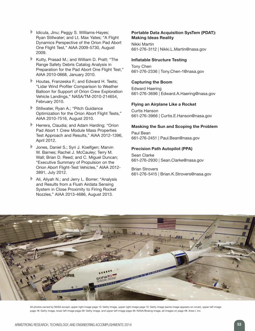
53ARMSTRONG RESEARCH, TECHNOLOGY, AND ENGINEERING ACCOMPLISHMENTS 2014
} Idicula, Jinu; Peggy S. Williams-Hayes; Ryan Stillwater; and Lt. Max Yates; “A Flight Dynamics Perspective of the Orion Pad Abort One Flight Test,” AIAA 2009-5730, August 2009.
} Kutty, Prasad M.; and William D. Pratt; “The Range Safety Debris Catalog Analysis in Preparation for the Pad Abort One Flight Test,” AIAA 2010-0668, January 2010.
} Houtas, Franzeska F.; and Edward H. Teets; “Lidar Wind Profiler Comparison to Weather Balloon for Support of Orion Crew Exploration Vehicle Landings,” NASA/TM-2010-214654, February 2010.
} Stillwater, Ryan A.; “Pitch Guidance Optimization for the Orion Abort Flight Tests,” AIAA 2010-7516, August 2010.
} Herrera, Claudia; and Adam Harding; “Orion Pad Abort 1 Crew Module Mass Properties Test Approach and Results,” AIAA 2012-1396, April 2012.
} Jones, Daniel S.; Syri J. Koelfgen; Marvin W. Barnes; Rachel J. McCauley; Terry M. Wall; Brian D. Reed; and C. Miguel Duncan; “Executive Summary of Propulsion on the Orion Abort Flight-Test Vehicles,” AIAA 2012-3891, July 2012.
} Ali, Aliyah N.; and Jerry L. Borrer; “Analysis and Results from a Flush Airdata Sensing System in Close Proximity to Firing Rocket Nozzles,” AIAA 2013-4686, August 2013.
Portable Data Acquisition SysTem (PDAT): Making Ideas RealityNikki Martin 661-276-3112 | [email protected]
Inflatable Structure TestingTony Chen 661-276-2336 | [email protected]
Capturing the BoomEdward Haering 661-276-3696 | [email protected]
Flying an Airplane Like a RocketCurtis Hanson 661-276-3966 | [email protected]
Masking the Sun and Scoping the ProblemPaul Bean 661-276-2451 | [email protected]
Precision Path Autopilot (PPA)Sean Clarke 661-276-2930 | [email protected]
Brian Strovers 661-276-5415 | [email protected]
All photos owned by NASA except: upper right image page 13: Getty Image, upper right image page 15: Getty image (same image appears on cover), upper left image
page 18: Getty image, lower left image page 28: Getty image, and upper left image page 46: NASA/Boeing image, all images on page 48: Area-I, Inc.

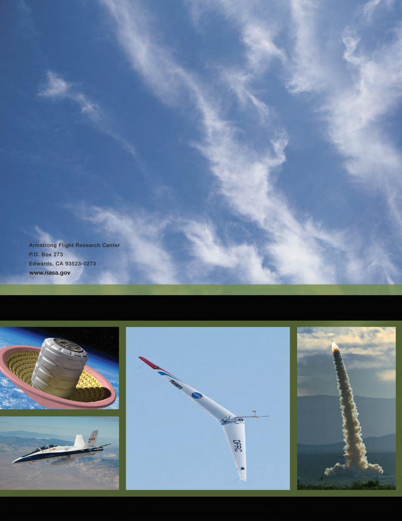
Armstrong Flight Research CenterP.O. Box 273Edwards, CA 93523-0273www.nasa.gov