reserved. api rp 571 overview: rights damage …...a) depending on service conditions, corrosion is...
TRANSCRIPT

1
Aust in, Texas May 19, 2015
AFPM Maintenance and Reliability Conference
by Jerold Danis
Equity Engineering
API RP 571 Overview: Damage Mechanisms in the Refining Industry
PROPRIETARY INFORMATION
Copyri
ght ©
2015
E²G
| The
Equ
ity E
ngine
ering
Grou
p, Inc
. All R
ights
Reserv
ed.

2
Schedule
Introduction Damage Mechanisms - General API 571 Overview The Crude / Vacuum Unit Sulfidation (Sulfidic Corrosion) Naphthenic Acid Corrosion (NAC) Ammonium Chloride Corrosion Hydroprocessing Units Ammonium Bisulfide Corrosion HTHA DMs and Current Initiatives
Copyri
ght ©
2015
E²G
| The
Equ
ity E
ngine
ering
Grou
p, Inc
. All R
ights
Reserv
ed.
3
Damage Mechanisms - General Refinery Materials
Refineries constructed out of a wide variety of materials: – Carbon steel – Alloy steels (e.g.,1.25Cr-0.5Mo, 9Cr-1Mo) – Stainless steels (e.g.,300 series and 400 series, duplex) – Nickel based (e.g. Alloy 625, Alloy 400 or Alloy C276) – Titanium (e.g. Grade 2 or Grade 12) – Copper based (e.g. Admiralty brass)
Each material subjected to some form of damage during service exposure
Copyri
ght ©
2015
E²G
| The
Equ
ity E
ngine
ering
Grou
p, Inc
. All R
ights
Reserv
ed.
4
In-Service Damage Types
General Corrosion
Localized Corrosion
Pitting, Crevice, Grooving Corrosion
Planar Cracks
Branched Cracks
Metallurgical Changes & Hydrogen Effects
Distortion
Copyri
ght ©
2015
E²G
| The
Equ
ity E
ngine
ering
Grou
p, Inc
. All R
ights
Reserv
ed.

5
In-Service Damage Types General Corrosion
Note uniform thinning Cop
yrigh
t © 20
15 E
²G | T
he E
quity
Eng
ineeri
ng G
roup,
Inc. A
ll Righ
ts Res
erved
.
6
In-Service Damage Types General Corrosion
Moderate variability over a large area: +/- 25 mils (0.025 inch / 0.64 mm).
– High Temperature Sulfur Corrosion
– H2 / H2S Corrosion
– Oxidation
– Atmospheric Corrosion
Usually can address thickness at corrosion monitoring locations (CMLs) with either ultrasonics (UT) or radiography (RT).
Copyri
ght ©
2015
E²G
| The
Equ
ity E
ngine
ering
Grou
p, Inc
. All R
ights
Reserv
ed.

7
In-Service Damage Types Localized Corrosion
Copyri
ght ©
2015
E²G
| The
Equ
ity E
ngine
ering
Grou
p, Inc
. All R
ights
Reserv
ed.

8
In-Service Damage Types Localized Corrosion
High variability of corrosion rate or damage only present in small region. – Corrosion Under Insulation (CUI) – Sour Water(NH4HS) – Naphthenic Acid Corrosion – Galvanic Corrosion – Erosion/Corrosion – Injection Point and Dead-leg Corrosion
Difficult to handle with CMLs (requires grid, scanning UT, RT, and global methods).
Copyri
ght ©
2015
E²G
| The
Equ
ity E
ngine
ering
Grou
p, Inc
. All R
ights
Reserv
ed.

9
In-Service Damage Types Pitting Corrosion
Copyri
ght ©
2015
E²G
| The
Equ
ity E
ngine
ering
Grou
p, Inc
. All R
ights
Reserv
ed.
10
In-Service Damage Types Pitting, Crevice, and Grooving Corrosion
Damage present with a high depth to area ratio. – Water services
– Under deposit corrosion, e.g., amine salts
– Weld knifeline attack
Difficult to detect with UT, RT normally required.
Copyri
ght ©
2015
E²G
| The
Equ
ity E
ngine
ering
Grou
p, Inc
. All R
ights
Reserv
ed.
11
In-Service Damage Types Planar Cracks
Copyri
ght ©
2015
E²G
| The
Equ
ity E
ngine
ering
Grou
p, Inc
. All R
ights
Reserv
ed.

12
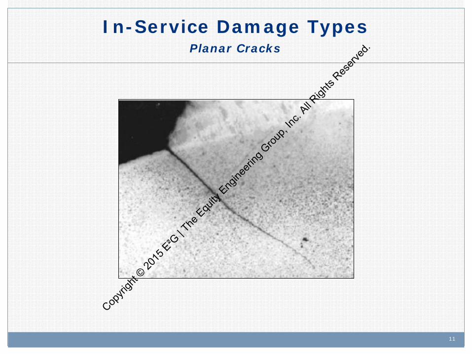
In-Service Damage Types Planar Cracks
Straight, unbranched cracks that normally initiate at a weld. – Mechanical fatigue, e.g., cracking at attachments – Thermal fatigue
If the cracks are on the outside surface, NDE typically: – MT – Magnetic particle testing – PT – Liquid penetrant testing – ACFM – Alternating current field measurement
If the cracks are on the inside surface, NDE typically: – UT shearwave, however it is difficult to know where to look. – Acoustic emission (AE) may be an option.
Copyri
ght ©
2015
E²G
| The
Equ
ity E
ngine
ering
Grou
p, Inc
. All R
ights
Reserv
ed.

13
In-Service Damage Types Branched Cracks
Copyri
ght ©
2015
E²G
| The
Equ
ity E
ngine
ering
Grou
p, Inc
. All R
ights
Reserv
ed.
14
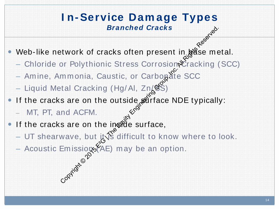
In-Service Damage Types Branched Cracks
Web-like network of cracks often present in base metal. – Chloride or Polythionic Stress Corrosion Cracking (SCC) – Amine, Ammonia, Caustic, or Carbonate SCC – Liquid Metal Cracking (Hg/Al, Zn/SS)
If the cracks are on the outside surface NDE typically: – MT, PT, and ACFM.
If the cracks are on the inside surface, – UT shearwave, but it is difficult to know where to look. – Acoustic Emission (AE) may be an option.
Copyri
ght ©
2015
E²G
| The
Equ
ity E
ngine
ering
Grou
p, Inc
. All R
ights
Reserv
ed.
15
In-Service Damage Types Metallurgical Changes & Hydrogen Effects
Copyri
ght ©
2015
E²G
| The
Equ
ity E
ngine
ering
Grou
p, Inc
. All R
ights
Reserv
ed.

16
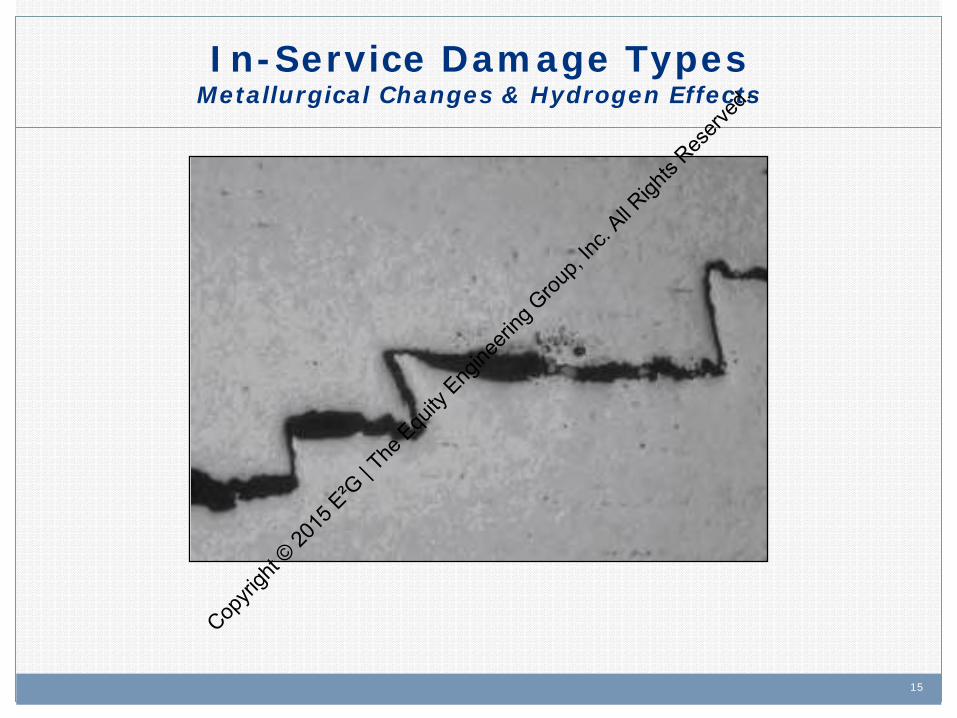
In-Service Damage Types Metallurgical Changes & Hydrogen Effects
Hydrogen Induced Cracking (HIC) Embrittlement (885°F (475°C), Sigma, Temper Embrittlement) Creep High Temperature Hydrogen Attack (HTHA) A combination of the following methods can be used:
– Field Metallography/Replication (FMR) – Mechanical testing, e.g., hardness testing, impact testing – NDE, e.g., Ultrasonic Testing (UT), WFMT
Copyri
ght ©
2015
E²G
| The
Equ
ity E
ngine
ering
Grou
p, Inc
. All R
ights
Reserv
ed.
17
In-Service Damage Types Distortion
Copyri
ght ©
2015
E²G
| The
Equ
ity E
ngine
ering
Grou
p, Inc
. All R
ights
Reserv
ed.

18
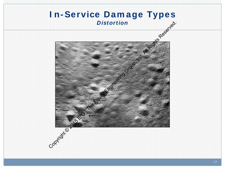
In-Service Damage Types Distortion
Blistering – damage associated with corrosion product (atomic) hydrogen charging into steel and forming molecular hydrogen at imperfections in the plate.
Bulging – typically from local hot spots and applied pressure loading.
Creep – time dependent strain accumulation associated with applied stress at elevated temperatures.
Copyri
ght ©
2015
E²G
| The
Equ
ity E
ngine
ering
Grou
p, Inc
. All R
ights
Reserv
ed.

19
Assessing Damage
Material - chemistry, heat treatment, strength level, etc. Morphology of damage. Service exposure - normal (operating conditions, corrosives,
concentration) and upset (carryover, fouling, leaking valves). How quickly did damage occur? Mitigating factors - coking, residual stresses, coatings, chemical
additives, water wash. Any stream monitoring or other warning systems data (e.g.,
probes). Human factors Previous inspections and their effectiveness at targeting the
particular mechanisms.
Copyri
ght ©
2015
E²G
| The
Equ
ity E
ngine
ering
Grou
p, Inc
. All R
ights
Reserv
ed.

20
Sources of Damage Information
API Publications National Association of Corrosion Engineers (NACE) Welding Research Council (WRC) General Publications (e.g., AICHE, Hydrocarbon
Processing, Oil & Gas Journal, etc.)
Copyri
ght ©
2015
E²G
| The
Equ
ity E
ngine
ering
Grou
p, Inc
. All R
ights
Reserv
ed.

21
American Petroleum Institute (API)
API Publications – API 571 - Damage Mechanisms – API 572 - Inspection of Pressure Vessels – API 574 - Inspection Practices for Piping System Components – API 575 - Inspection of Atmospheric & Low Pressure Storage Tanks – API 579 - FFS, Appendix G – API 581 - RBI Technology – API 932-B – REAC – API 934 A/B/C/D/E – Heavy Wall CrMo – API 938-C – Duplex SS – API 939-A - Wet H2S Cracking – API 939-B – Repair Strategies for Equipment in Wet H2S Service – API 939-C – Guidelines for Avoiding Sulfidation Corrosion – API 939 D & E - Ethanol SCC – API 941 - Hydrogen Attack – API 945 - Environmental Cracking in Amine Units
Cop
yrigh
t © 20
15 E
²G | T
he E
quity
Eng
ineeri
ng G
roup,
Inc. A
ll Righ
ts Res
erved
.
22
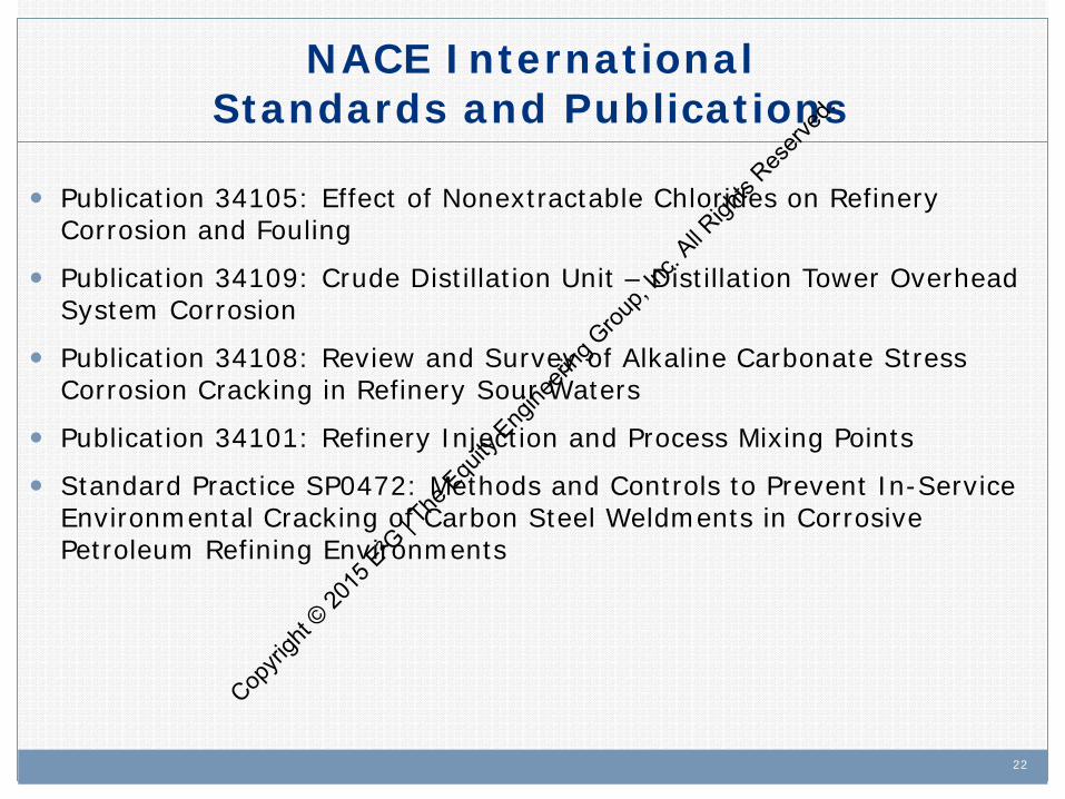
NACE International Standards and Publications
Publication 34105: Effect of Nonextractable Chlorides on Refinery Corrosion and Fouling
Publication 34109: Crude Distillation Unit – Distillation Tower Overhead System Corrosion
Publication 34108: Review and Survey of Alkaline Carbonate Stress Corrosion Cracking in Refinery Sour Waters
Publication 34101: Refinery Injection and Process Mixing Points
Standard Practice SP0472: Methods and Controls to Prevent In-Service Environmental Cracking of Carbon Steel Weldments in Corrosive Petroleum Refining Environments
Copyri
ght ©
2015
E²G
| The
Equ
ity E
ngine
ering
Grou
p, Inc
. All R
ights
Reserv
ed.

23
Copyri
ght ©
2015
E²G
| The
Equ
ity E
ngine
ering
Grou
p, Inc
. All R
ights
Reserv
ed.
24
API RP 571 Overview: Damage Mechanisms in the
Refining Industry
API RP 571 Overview Cop
yrigh
t © 20
15 E
²G | T
he E
quity
Eng
ineeri
ng G
roup,
Inc. A
ll Righ
ts Res
erved
.
25 25
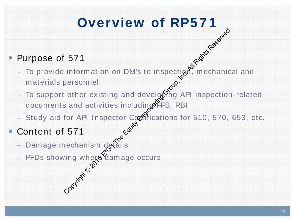
Purpose of 571 – To provide information on DM’s to inspection, mechanical and
materials personnel – To support other existing and developing API inspection-related
documents and activities including FFS, RBI – Study aid for API Inspector Certifications for 510, 570, 653, etc.
Content of 571 – Damage mechanism details – PFDs showing where damage occurs
Overview of RP571
Copyri
ght ©
2015
E²G
| The
Equ
ity E
ngine
ering
Grou
p, Inc
. All R
ights
Reserv
ed.

26 26
Damage Mechanism Description
More than 60 damage mechanisms common to the refining and petrochemical industry are included in API 571 – Second Edition April 2011
These can be grouped into five general categories:
1. Corrosion (general and localized)
2. Stress corrosion cracking (environmental)
3. Mechanical
4. Metallurgical
5. Other
Copyri
ght ©
2015
E²G
| The
Equ
ity E
ngine
ering
Grou
p, Inc
. All R
ights
Reserv
ed.
27
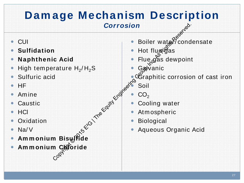
Damage Mechanism Description Corrosion
CUI Sulfidation Naphthenic Acid High temperature H2/H2S Sulfuric acid HF Amine Caustic HCl Oxidation Na/V Ammonium Bisulfide Ammonium Chloride
Boiler water/condensate Hot flue gas Flue gas dewpoint Galvanic Graphitic corrosion of cast iron Soil CO2
Cooling water Atmospheric Biological Aqueous Organic Acid
Copyri
ght ©
2015
E²G
| The
Equ
ity E
ngine
ering
Grou
p, Inc
. All R
ights
Reserv
ed.

28 28
Damage Mechanism Description Stress Corrosion Cracking
Caustic
Amine
Carbonate
Polythionic
Chloride
Sulfide
Liquid Metal Cracking
Ethanol
Sulfate Cop
yrigh
t © 20
15 E
²G | T
he E
quity
Eng
ineeri
ng G
roup,
Inc. A
ll Righ
ts Res
erved
.
29 29
Damage Mechanism Description Mechanical Mechanisms
Mechanical fatigue
Thermal fatigue
Brittle fracture
Creep and stress rupture
Copyri
ght ©
2015
E²G
| The
Equ
ity E
ngine
ering
Grou
p, Inc
. All R
ights
Reserv
ed.
30 30
Damage Mechanism Description Metallurgical Mechanisms
Sigma Phase embrittlement
885 Embrittlement
Graphitization
Spheroidization
Temper embrittlement
Copyri
ght ©
2015
E²G
| The
Equ
ity E
ngine
ering
Grou
p, Inc
. All R
ights
Reserv
ed.
31 31
Damage Mechanism Description Other Mechanisms
Hydriding HIC/SOHIC Corrosion fatigue (deaerators) High Temperature Hydrogen Attack (HTHA) Dealloying Cavitation Erosion Reheat Cracking Carburization Metal dusting Nitriding Gaseous Oxygen Enhanced Ignition & Combustion
Copyri
ght ©
2015
E²G
| The
Equ
ity E
ngine
ering
Grou
p, Inc
. All R
ights
Reserv
ed.
32 32
Organization of 571
Description of Damage Affected Materials Critical Factors Affected Units or Equipment Appearance or Morphology of Damage Prevention/Mitigation Inspection & Monitoring Related Mechanisms References
Copyri
ght ©
2015
E²G
| The
Equ
ity E
ngine
ering
Grou
p, Inc
. All R
ights
Reserv
ed.

33
2.4.1 Sulfidation
2.4.1.1 Description of Damage Corrosion of carbon steel and other alloys resulting from their reaction with sulfur compounds in high temperature environments. The presence of hydrogen accelerates corrosion.
2.4.1.2 Affected Materials a) All iron based materials including carbon steel and low alloy steels, 300 Series SS, and 400 Series SS. b) Nickel base alloys are also affected to varying degrees depending on composition, especially chromium
content. c) Copper base alloys form sulfide at lower temperatures than carbon steel.
2.4.1.3 Critical Factors a) Major factors affecting sulfidation are alloy composition, temperature, and concentration of corrosive
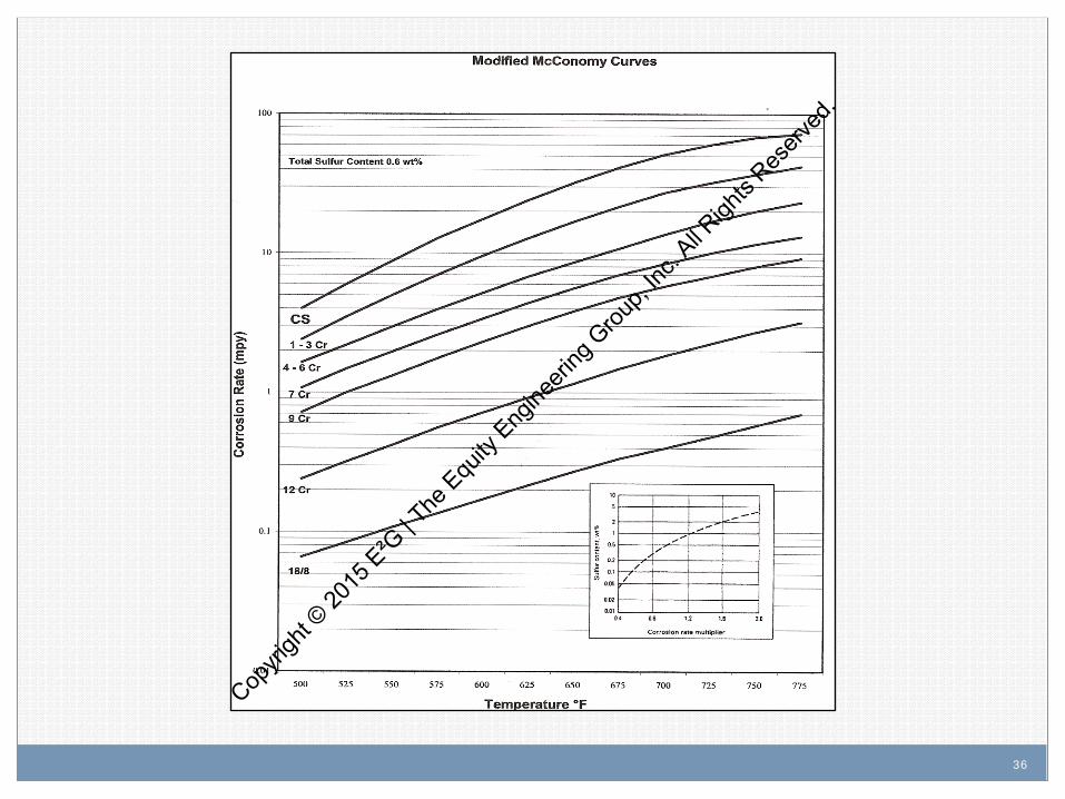
sulfur compounds. b) Susceptibility of an alloy to sulfidation is determined by its ability to form protective sulfide scales. c) Sulfidation of iron-based alloys usually begins at metal temperatures above 500oF (260oC). The typical
effects of increasing temperature, chromium content, and sulfur content on metal loss are shown in Figure 2.4.2.1 and Figure 2.4.2.2.
d) In general, the resistance of iron and nickel base alloys is determined by the chromium content of the material. Increasing the chromium content significantly increases resistance to sulfidation. 300 Series SS, such as Types 304, 316, 321, and 347, are highly resistant in most refining process environments. Nickel base alloys are similar to stainless steels in that similar levels of chromium provide similar resistance to sulfidation.
Copyri
ght ©
2015
E²G
| The
Equ
ity E
ngine
ering
Grou
p, Inc
. All R
ights
Reserv
ed.
34
2.4.1.4 Appearance or Morphology of Damage
a) Depending on service conditions, corrosion is most often in the form of uniform thinning but can also occur as localized corrosion or high velocity erosion-corrosion damage.
b) A sulfide scale will usually cover the surface of components. Deposits may be thick or thin depending on the alloy, corrosiveness of the stream, fluid velocities, and presence of contaminants. (See Figure 2.4.2.3.)
2.4.1.5 Prevention / Mitigation
a) Resistance to sulfidation is generally achieved by upgrading to a higher chromium alloy.
b) Piping and equipment constructed from solid or clad 300 Series SS or 400 Series SS can provide significant resistance to corrosion.
c) Aluminum diffusion treatment of low alloy steel components is sometimes used to reduce sulfidation rates and minimize scale formation, however, it may not offer complete protection. 300 Series SS catalyst support screens in hydroprocessing reactors can also be treated to prolong life.
2.4.1.6 Inspection and Monitoring
a) Process conditions should be monitored for increasing temperatures and/or changing sulfur levels.
b) Temperatures can be monitored through the use of tubeskin thermocouples and/or infrared thermography.
c) Evidence of thinning can be detected using external ultrasonic thickness measurements and profile radiography.
Copyri
ght ©
2015
E²G
| The
Equ
ity E
ngine
ering
Grou
p, Inc
. All R
ights
Reserv
ed.

35
2.4.1.7 Related Mechanisms Sulfidation is also known as sulfidic corrosion. High temperature sulfidation in the presence of hydrogen is covered in High Temp H2/H2S Corrosion (Section 3.1.1.5).
2.4.1.8 References 1. H.F. McConomy, “High Temperature Sulfidic Corrosion in Hydrogen-Free Environments,” API
Proceedings, Vol. 43, (III), pp. 78-96, 1963. 2. J. Gutzeit, “High Temperature Sulfidic Corrosion of Steels”, Process Industries Corrosion – The Theory
and Practice,” NACE International, Houston,TX, 1986, pp. 171-189. 3. J. Gutzeit et al., “Corrosion in Petroleum Refining and Petrochemical Operations,” ASM Metals
Handbook, Volume 13, 9th Edition, ASM International, OH, 1987, pp. 1262 – 1288. 4. E. B Backenstow et al, “ High Temperature Hydrogen Sulfide Corrosion”, CORROSION, Vol. 12, No. 1,
1956, pp 6t-16t. 5. NACE Task Group 176 Draft Report, “Overview of Sulfidic Corrosion in Petroleum Refining”, NACE
International, Houston, TX, 2003.
Copyri
ght ©
2015
E²G
| The
Equ
ity E
ngine
ering
Grou
p, Inc
. All R
ights
Reserv
ed.
36
Copyri
ght ©
2015
E²G
| The
Equ
ity E
ngine
ering
Grou
p, Inc
. All R
ights
Reserv
ed.
37 37
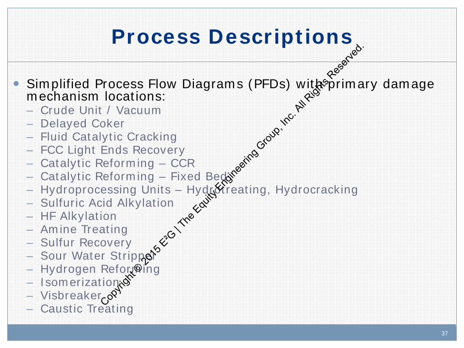
Process Descriptions
Simplified Process Flow Diagrams (PFDs) with primary damage mechanism locations: – Crude Unit / Vacuum – Delayed Coker – Fluid Catalytic Cracking – FCC Light Ends Recovery – Catalytic Reforming – CCR – Catalytic Reforming – Fixed Bed – Hydroprocessing Units – Hydrotreating, Hydrocracking – Sulfuric Acid Alkylation – HF Alkylation – Amine Treating – Sulfur Recovery – Sour Water Stripper – Hydrogen Reforming – Isomerization – Visbreaker – Caustic Treating
Cop
yrigh
t © 20
15 E
²G | T
he E
quity
Eng
ineeri
ng G
roup,
Inc. A
ll Righ
ts Res
erved
.

38
Copyri
ght ©
2015
E²G
| The
Equ
ity E
ngine
ering
Grou
p, Inc
. All R
ights
Reserv
ed.

39
Copyri
ght ©
2015
E²G
| The
Equ
ity E
ngine
ering
Grou
p, Inc
. All R
ights
Reserv
ed.

40
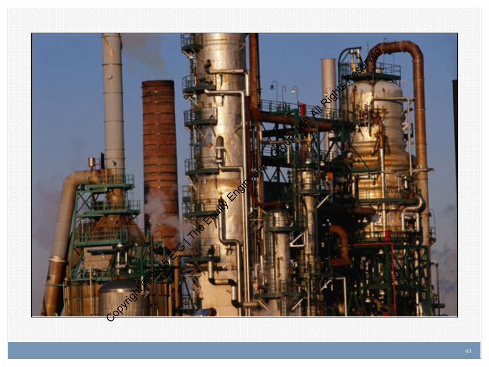
API RP 571 Overview: Damage Mechanisms in the
Refining Industry
The Crude/Vacuum Unit Cop
yrigh
t © 20
15 E
²G | T
he E
quity
Eng
ineeri
ng G
roup,
Inc. A
ll Righ
ts Res
erved
.
41
Copyri
ght ©
2015
E²G
| The
Equ
ity E
ngine
ering
Grou
p, Inc
. All R
ights
Reserv
ed.
42 42
In the Crude/Vacuum Unit preheated crude oil is treated
to remove salts and then further heated to facilitate separation of the hydrocarbon (crude oil) in a distillation tower. – Different fractions (cuts/product streams) are drawn off after
condensing. – Each of these streams is subsequently processed in
downstream units. Note: the final distillation steps are performed under
vacuum conditions to maximize liquid recovery.
Brief Process Description
Copyri
ght ©
2015
E²G
| The
Equ
ity E
ngine
ering
Grou
p, Inc
. All R
ights
Reserv
ed.

43 43
Feed Stream: – Crude Oil
Products: – LPG (Liquefied Petroleum Gas), e.g. propane and butane
– Naphtha
– Kerosene/Jet Fuel
– Diesel/Atmospheric Gas Oil
– Crude Tower Bottoms (Atmospheric Resid)
– Vacuum Gas Oils (e.g., LVGO, MVGO,HVGO)
– Vacuum Tower Bottoms (Vacuum Resid)
Crude Unit Feed and Products
Copyri
ght ©
2015
E²G
| The
Equ
ity E
ngine
ering
Grou
p, Inc
. All R
ights
Reserv
ed.
44 44
Desalter wash water
Caustic (optional)
Chemical treatments – Filming amines
– Neutralizers
– Demulsifiers
Tower overhead wash water (optional)
Other Primary Streams
Copyri
ght ©
2015
E²G
| The
Equ
ity E
ngine
ering
Grou
p, Inc
. All R
ights
Reserv
ed.
45 45
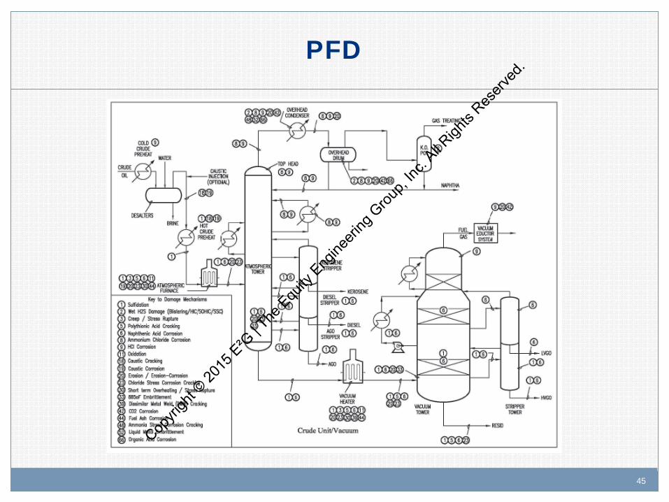
PFD
Copyri
ght ©
2015
E²G
| The
Equ
ity E
ngine
ering
Grou
p, Inc
. All R
ights
Reserv
ed.

46 46
S - promotes sulfidation.
Naphthenic acid (organic acids) - causes corrosion.
Chlorides - forms HCl, ammonium chloride, amine hydrochloride.
NaOH (caustic)- poisons FCC catalyst and can lead to coking.
Nitrogen - contributes to ammonia formation.
Contaminants
Copyri
ght ©
2015
E²G
| The
Equ
ity E
ngine
ering
Grou
p, Inc
. All R
ights
Reserv
ed.
47 47
Metal temperature (sulfidation).
Velocity (naphthenic acid).
Desalter efficiency (chloride removal).
Desalter wash water pH (NH3 in crude).
pH in crude tower reflux drum (HCl formation).
Reflux temperature (shock condensation).
Some Process Parameters Affecting Damage
Copyri
ght ©
2015
E²G
| The
Equ
ity E
ngine
ering
Grou
p, Inc
. All R
ights
Reserv
ed.

48 48
CS
Low alloy steels (5Cr, 9Cr)
High alloy (12Cr) stainless steels, e.g., 410, 405, 410S
Austenitic stainless steels, e.g., 304, 316, 317
Nickel copper/nickel moly alloys, e.g., Alloy 400, Alloy C-276
Titanium
Materials of Construction
Copyri
ght ©
2015
E²G
| The
Equ
ity E
ngine
ering
Grou
p, Inc
. All R
ights
Reserv
ed.
49 49
Sulfidation
Naphthenic Acid Corrosion (NAC)
HCl Corrosion
Ammonium Chloride Corrosion
885°F Embrittlement
Primary Damage Mechanisms
Copyri
ght ©
2015
E²G
| The
Equ
ity E
ngine
ering
Grou
p, Inc
. All R
ights
Reserv
ed.

50
Copyri
ght ©
2015
E²G
| The
Equ
ity E
ngine
ering
Grou
p, Inc
. All R
ights
Reserv
ed.
51
API RP 571 Overview: Damage Mechanisms in the
Refining Industry
Sulfidation (Sulfidic Corrosion) Cop
yrigh
t © 20
15 E
²G | T
he E
quity
Eng
ineeri
ng G
roup,
Inc. A
ll Righ
ts Res
erved
.
52 52
Description of Damage
Sulfidation refers to the corrosion of CS and other metallic materials resulting from their reaction with sulfur compounds in high temperature (hydrogen free) environments.
Note: The presence of hydrogen accelerates corrosion and creates a different corrosion mechanism (H2/H2S) than addressed in this discussion.
Copyri
ght ©
2015
E²G
| The
Equ
ity E
ngine
ering
Grou
p, Inc
. All R
ights
Reserv
ed.
53 53
Affected Materials
Carbon steel
Low alloy steels
300 Series SS
400 Series SS
Nickel base alloys
Copyri
ght ©
2015
E²G
| The
Equ
ity E
ngine
ering
Grou
p, Inc
. All R
ights
Reserv
ed.
54 54
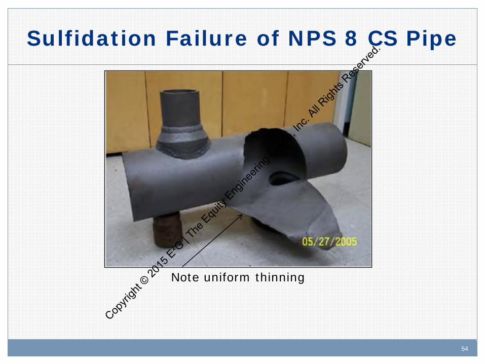
Sulfidation Failure of NPS 8 CS Pipe
Note uniform thinning
Copyri
ght ©
2015
E²G
| The
Equ
ity E
ngine
ering
Grou
p, Inc
. All R
ights
Reserv
ed.
55 55
Critical Factors
Major factors are alloy composition, temperature and concentration of corrosive sulfur compounds as shown in the Modified McConomy curves. – Increasing Cr content improves corrosion resistance.
– Corrosion increases at temperatures >500oF (260oC). – While crude oils contain many different sulfur compounds,
sulfidation is primarily caused by H2S and other reactive sulfur species as a result of the thermal decomposition of sulfur compounds at high temperatures.
It can be misleading to predict corrosion rates based on total (weight %) sulfur alone since some compounds react more readily to form H2S. However, the Modified McConomy curves are based on total sulfur.
Copyri
ght ©
2015
E²G
| The
Equ
ity E
ngine
ering
Grou
p, Inc
. All R
ights
Reserv
ed.

56
Copyri
ght ©
2015
E²G
| The
Equ
ity E
ngine
ering
Grou
p, Inc
. All R
ights
Reserv
ed.
57 57
Susceptibility of an alloy is determined by its ability to form protective sulfide scales.
Sulfide scales offer varying degrees of protection depending on the alloy and the severity of the process stream. – The 400 series (e.g., 405,410,410S) and especially the 300
series SS (e.g., 304,316,321,347) are highly resistant.
Carbon steel with <0.10% Si (e.g., A53 piping) is susceptible to higher rates of corrosion than steels with >0.10% Si (e.g., A106 piping).
Critical Factors
Copyri
ght ©
2015
E²G
| The
Equ
ity E
ngine
ering
Grou
p, Inc
. All R
ights
Reserv
ed.
58 58
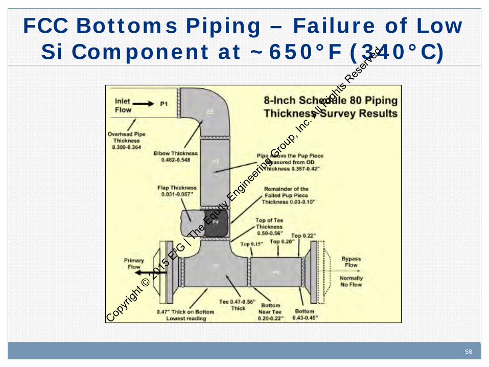
FCC Bottoms Piping – Failure of Low Si Component at ~650°F (340°C)
Copyri
ght ©
2015
E²G
| The
Equ
ity E
ngine
ering
Grou
p, Inc
. All R
ights
Reserv
ed.

59 59
Actual Failure Shown in Previous Slide
Copyri
ght ©
2015
E²G
| The
Equ
ity E
ngine
ering
Grou
p, Inc
. All R
ights
Reserv
ed.

60 60
API 939-C Sulfidation Impact of Si
Copyri
ght ©
2015
E²G
| The
Equ
ity E
ngine
ering
Grou
p, Inc
. All R
ights
Reserv
ed.
61 61
Affected Units or Equipment
Piping and equipment in high temperature environments where sulfur-containing streams are processed.
Common areas of concern are the crude/vacuum, FCC, coker, visbreaker and feed system of hydroprocessing units.
Heaters fired with oil, gas, coke and most other sources of fuel may be affected depending on sulfur levels in the fuel.
Boilers and high temperature equipment exposed to sulfur-containing gases can be affected.
Copyri
ght ©
2015
E²G
| The
Equ
ity E
ngine
ering
Grou
p, Inc
. All R
ights
Reserv
ed.
62 62
Appearance or Morphology of Damage
Most often in the form of uniform thinning, but also occurs as localized corrosion or high velocity erosion-corrosion damage.
A sulfide scale will usually cover the surface. Deposits may be thick or thin depending on the alloy, corrosiveness of the stream, and fluid velocities.
Copyri
ght ©
2015
E²G
| The
Equ
ity E
ngine
ering
Grou
p, Inc
. All R
ights
Reserv
ed.
63 63
Prevention/Mitigation
Resistance to sulfidation is generally achieved by upgrading to a higher chromium alloy. – Upgrading to 300 Series SS or 400 Series SS can provide
significant resistance to corrosion.
Aluminum diffusion treatment of low alloy steel components is sometimes used to reduce sulfidation rates and minimize scale formation. However, it may not offer complete protection.
Copyri
ght ©
2015
E²G
| The
Equ
ity E
ngine
ering
Grou
p, Inc
. All R
ights
Reserv
ed.
64 64
Inspection and Monitoring
Inspection
– Conduct thickness surveys – Proactive and retroactive PMI recommended to check for
alloy mix-ups
Operations
– Monitor process conditions for increasing temperature or changes in sulfur content
Copyri
ght ©
2015
E²G
| The
Equ
ity E
ngine
ering
Grou
p, Inc
. All R
ights
Reserv
ed.

65 65
Key References
NACE Publication 34103 – Overview of Sulfidic Corrosion in Petroleum Refining
API RP 939-C – Guidelines for Avoiding Sulfidation (Sulfidic) Corrosion Failures in Oil Refineries
Copyri
ght ©
2015
E²G
| The
Equ
ity E
ngine
ering
Grou
p, Inc
. All R
ights
Reserv
ed.
66
Copyri
ght ©
2015
E²G
| The
Equ
ity E
ngine
ering
Grou
p, Inc
. All R
ights
Reserv
ed.
67
API RP 571 Overview: Damage Mechanisms in the
Refining Industry
Naphthenic Acid Corrosion
(NAC) Copyri
ght ©
2015
E²G
| The
Equ
ity E
ngine
ering
Grou
p, Inc
. All R
ights
Reserv
ed.
68 68
Description of Damage
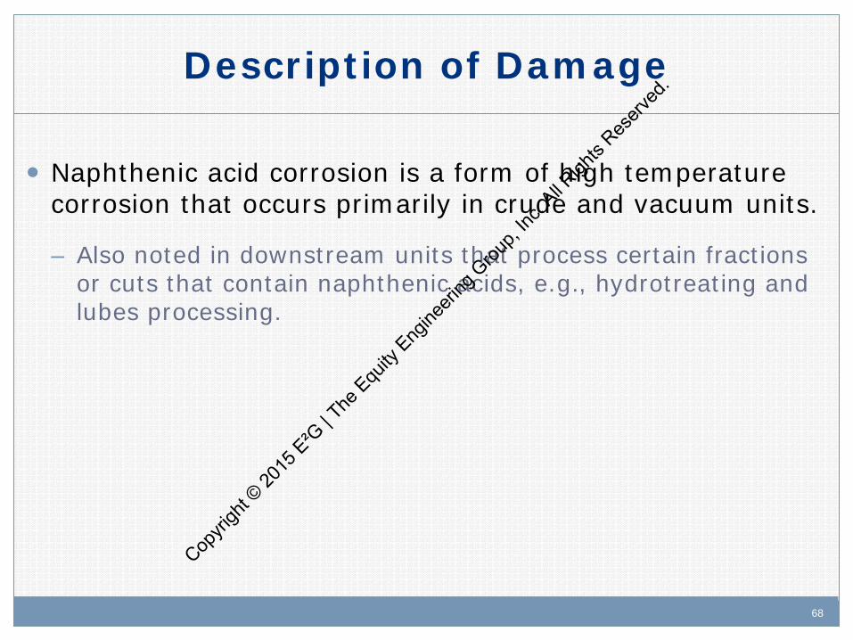
Naphthenic acid corrosion is a form of high temperature corrosion that occurs primarily in crude and vacuum units.
– Also noted in downstream units that process certain fractions or cuts that contain naphthenic acids, e.g., hydrotreating and lubes processing.
Copyri
ght ©
2015
E²G
| The
Equ
ity E
ngine
ering
Grou
p, Inc
. All R
ights
Reserv
ed.

69 69
Affected Materials
Carbon steel
Low alloy steels
400 Series SS
300 Series SS
Nickel base alloys
Copyri
ght ©
2015
E²G
| The
Equ
ity E
ngine
ering
Grou
p, Inc
. All R
ights
Reserv
ed.

70 70
Critical Factors
NAC is a function of the specific naphthenic acids present (molecular weight), temperature, sulfur content, velocity and alloy composition.
Naphthenic acid content: Reported as Neutralization Number (Neut Number) or Total Acid Number (TAN). These are measures of the acidity (organic acid content) as determined by ASTM test methods, e.g. ASTM D-664.
Temperature: Normally occurs in streams above 425oF (218oC) but has been reported down to 350oF (177oC). Severity increases with temp up to about 750°F (399oC).
Sulfur Content: Promotes iron sulfide formation and can have an inhibiting effect on NAC. Cop
yrigh
t © 20
15 E
²G | T
he E
quity
Eng
ineeri
ng G
roup,
Inc. A
ll Righ
ts Res
erved
.

71 71
Critical Factors
Velocity: Corrosion is most severe in two phase (liquid and vapor) flow, in areas of high velocity or turbulence and in distillation towers where hot vapors condense to form liquid phase droplets, e.g., at the underside of trays. Note: Recent JIP laboratory studies have highlighted the importance of wall shear stress vs velocity.
Alloy Composition: Increasing amounts of molybdenum show improved resistance. A minimum of 2% to 2.5% is required depending on the aggressiveness (TAN?) of the whole crude and its side cuts, i.e., 316SS (2-3% Mo) or 317SS (3-4% Mo).
Copyri
ght ©
2015
E²G
| The
Equ
ity E
ngine
ering
Grou
p, Inc
. All R
ights
Reserv
ed.
72 72
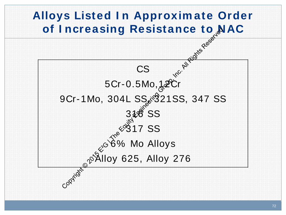
CS 5Cr-0.5Mo,12Cr
9Cr-1Mo, 304L SS, 321SS, 347 SS 316 SS 317 SS
6% Mo Alloys Alloy 625, Alloy 276
Alloys Listed In Approximate Order of Increasing Resistance to NAC
Copyri
ght ©
2015
E²G
| The
Equ
ity E
ngine
ering
Grou
p, Inc
. All R
ights
Reserv
ed.
73 73
The TAN of the crude may be misleading because this family of acids has a range of boiling points and tends to concentrate in various cuts. Important to measure TAN in cuts of interest.
No widely available prediction methods (other than industry JIP) have been developed to correlate corrosion rate with the various factors influencing it.
Severity of corrosion often (but not always) increases with increasing TAN of the hydrocarbon phase. – The various acids which comprise the naphthenic acid family can
have distinctly different corrosivity.
Historically, TAN values <0.5 were not considered corrosive. However, NAC can be a problem with low sulfur crudes (<0.5 wt% S) with TANs as low as 0.10.
Critical Factors
Copyri
ght ©
2015
E²G
| The
Equ
ity E
ngine
ering
Grou
p, Inc
. All R
ights
Reserv
ed.
74 74
NAC is associated with hot liquid hydrocarbon streams. Normally not seen in all vapor phase.
Naphthenic acids remove protective iron sulfide scales on the surface of metals – forms iron naphthenate.
Naphthenic acids are destroyed in FCCU units. Data suggests that all austenitic stainless steels are unaffected
after the point of hydrogen injection in hydroprocessing units.
Critical Factors
Copyri
ght ©
2015
E²G
| The
Equ
ity E
ngine
ering
Grou
p, Inc
. All R
ights
Reserv
ed.

75 75
NAC in Vacuum Heater 5 Cr Outlet Elbow
Copyri
ght ©
2015
E²G
| The
Equ
ity E
ngine
ering
Grou
p, Inc
. All R
ights
Reserv
ed.
76 76
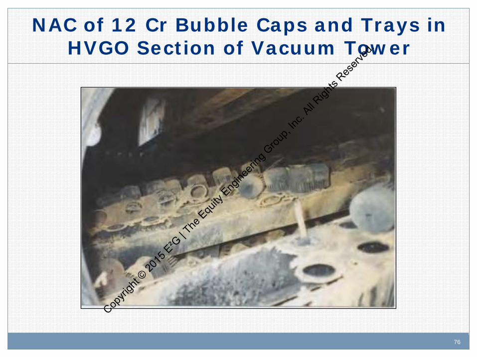
NAC of 12 Cr Bubble Caps and Trays in HVGO Section of Vacuum Tower
Copyri
ght ©
2015
E²G
| The
Equ
ity E
ngine
ering
Grou
p, Inc
. All R
ights
Reserv
ed.
77 77
Affected Units or Equipment
Crude Unit, VGO Hydrotreaters (e.g., CFHU), Lube Unit - extract circuit.
Crude & vacuum heater tubes, transfer lines, vacuum btms piping, AGO circuits, HVGO circuits (sometimes LVGO), pump internals.
Piping systems, e.g., valves, elbows, tees and reducers as well as areas of flow disturbance such as weld beads and thermowells.
Crude and vacuum tower may also be corroded in the flash zones, along with packing and internals where high acid streams condense or high velocity droplets impinge.
Copyri
ght ©
2015
E²G
| The
Equ
ity E
ngine
ering
Grou
p, Inc
. All R
ights
Reserv
ed.

78 78
Appearance or Morphology of Damage
NAC is characterized by:
– Localized corrosion.
– Pitting, especially in low velocity condensing systems.
– Flow induced grooving in high velocity areas, e.g., bear claws.
Copyri
ght ©
2015
E²G
| The
Equ
ity E
ngine
ering
Grou
p, Inc
. All R
ights
Reserv
ed.
79 79
Prevention/Mitigation
For units and/or components which have not been designed for NAC, the options are:
– Reduce NAC by blending crude to reduce the TAN and/or increase the sulfur content.
– Use NAC chemical inhibitor. Especially useful for intermittent processing of high TAN crudes; inhibitor effectiveness needs to be monitored carefully.
– For severe conditions, Type 317L stainless steel or other alloys with higher molybdenum content may be required.
Copyri
ght ©
2015
E²G
| The
Equ
ity E
ngine
ering
Grou
p, Inc
. All R
ights
Reserv
ed.

80 80
Inspection and Monitoring
Inspection: – Localized damage is difficult to find so RT should be the primary
detection method followed by UT thickness measurement. – Use electrical resistance corrosion probes and corrosion coupon racks. – Hydrogen flux probes have also been used to detect hydrogen
activity which may be indicative of NAC. Operations:
– Monitor TAN and sulfur content of the crude charge and side streams to determine the distribution of acids in the various cuts.
Copyri
ght ©
2015
E²G
| The
Equ
ity E
ngine
ering
Grou
p, Inc
. All R
ights
Reserv
ed.

81
Copyri
ght ©
2015
E²G
| The
Equ
ity E
ngine
ering
Grou
p, Inc
. All R
ights
Reserv
ed.
82
API RP 571 Overview: Damage Mechanisms in the
Refining Industry
Ammonium Chloride Corrosion Cop
yrigh
t © 20
15 E
²G | T
he E
quity
Eng
ineeri
ng G
roup,
Inc. A
ll Righ
ts Res
erved
.

83 83
Description of Damage
Ammonium chloride corrosion is typically a localized damage mechanism that occurs under salt deposits of ammonium chlorides. It results in pitting and frequently occurs in the absence of a water phase.
Note: Amine salts can form from over-injection of amine based
inhibitors and can also contribute to under deposit pitting.
Copyri
ght ©
2015
E²G
| The
Equ
ity E
ngine
ering
Grou
p, Inc
. All R
ights
Reserv
ed.
84 84
Affected Materials
In order of increasing resistance:
– Carbon steel and low alloy steels
– 300 Series SS and 400 Series SS
– Alloy 825
– Alloy 625 and C276
– Titanium
Note: Duplex SS (i.e., 2205) can be no better than CS
Copyri
ght ©
2015
E²G
| The
Equ
ity E
ngine
ering
Grou
p, Inc
. All R
ights
Reserv
ed.

85 85
Critical Factors
Concentration of NH3 and chlorides.
Temperature:
– Can deposit well above the water dewpoint – up to about 400°F (204°C).
– Corrosion rates increase with increasing temperature.
Availability of moisture - the salt is hygroscopic and will readily absorb water producing corrosion rates >100 mpy (>2.5mm/yr).
Salts are highly water soluble and can be flushed away by a water wash.
Copyri
ght ©
2015
E²G
| The
Equ
ity E
ngine
ering
Grou
p, Inc
. All R
ights
Reserv
ed.

86 86
Affected Units
Crude tower overheads.
FCCU and Coker fractionator overheads and top pumparounds.
Catalytic reforming effluent streams and overheads from light ends towers.
Hydroprocessing reactor effluent streams, e.g., naphtha and kero hydrotreaters.
Copyri
ght ©
2015
E²G
| The
Equ
ity E
ngine
ering
Grou
p, Inc
. All R
ights
Reserv
ed.
87 87
Appearance or Morphology of Damage
Salts may have been removed during clearing operations prior to opening equipment, and hence are not always seen.
When present, salts are typically white or brown. Often a voluminous FeS / FeCl2 scale is observed.
Corrosion is typically evident as localized pitting.
Copyri
ght ©
2015
E²G
| The
Equ
ity E
ngine
ering
Grou
p, Inc
. All R
ights
Reserv
ed.
88 88
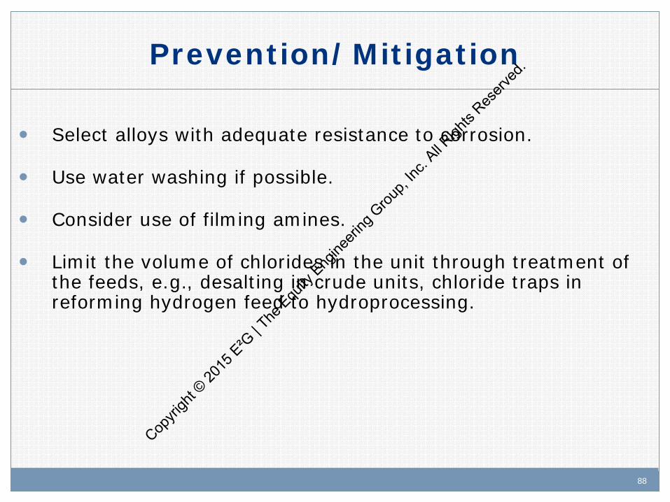
Prevention/Mitigation
Select alloys with adequate resistance to corrosion.
Use water washing if possible.
Consider use of filming amines.
Limit the volume of chlorides in the unit through treatment of the feeds, e.g., desalting in crude units, chloride traps in reforming hydrogen feed to hydroprocessing.
Copyri
ght ©
2015
E²G
| The
Equ
ity E
ngine
ering
Grou
p, Inc
. All R
ights
Reserv
ed.

89 89
Inspection and Monitoring
Inspection:
– Inspection is difficult due to localized nature of deposits, consequently, RT often more suitable than UT.
Operations:
– Steward wash water injection sites to ensure adequate water flow.
– Monitor for delta P buildup as an indicator of salting. Carbon steel exchanger bundles may be packed solid with FeS / FeCl2 scale resulting from corrosion.
– Work with chemical vendor to develop ionic model to establish salt deposition temperatures for monitoring.
Copyri
ght ©
2015
E²G
| The
Equ
ity E
ngine
ering
Grou
p, Inc
. All R
ights
Reserv
ed.

90
Copyri
ght ©
2015
E²G
| The
Equ
ity E
ngine
ering
Grou
p, Inc
. All R
ights
Reserv
ed.

91
API RP 571 Overview: Damage Mechanisms in the
Refining Industry
Hydroprocessing Units Cop
yrigh
t © 20
15 E
²G | T
he E
quity
Eng
ineeri
ng G
roup,
Inc. A
ll Righ
ts Res
erved
.

92 92
Brief Process Description
Hydroprocessing involves a reaction between hydrocarbon feed and hydrogen over a catalyst at elevated temperatures: – Removes sulfur and nitrogen to produce a clean
product. – Cracks the feed into higher value fractions
(hydrocracking).
Copyri
ght ©
2015
E²G
| The
Equ
ity E
ngine
ering
Grou
p, Inc
. All R
ights
Reserv
ed.
93 93
Hydroprocessing Feed and Products
Feed Streams: – Naphtha
– Diesel
– Vacuum Gas Oils (e.g., LVGO, MVGO,HVGO)
– Crude Tower Bottoms (Atmospheric Residue)
– Vacuum Tower Bottoms (Vacuum Residue)
• Products: – Low sulfur hydrocarbons (desulfurization)
– Low nitrogen hydrocarbons (de-nitrification)
– Cracked products (via Hydrocracking) and light ends
Cop
yrigh
t © 20
15 E
²G | T
he E
quity
Eng
ineeri
ng G
roup,
Inc. A
ll Righ
ts Res
erved
.
94 94
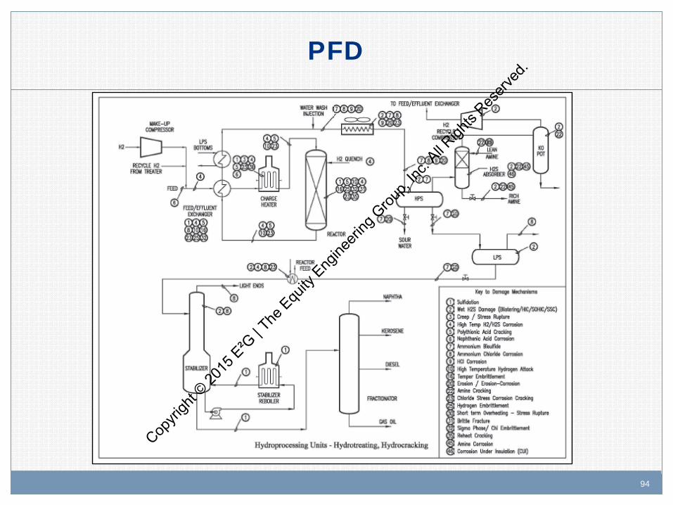
PFD
Copyri
ght ©
2015
E²G
| The
Equ
ity E
ngine
ering
Grou
p, Inc
. All R
ights
Reserv
ed.

95 95
Contaminants
S - contributes to sulfidation prior to the reactor.
H2S - combines with ammonia to form ammonium bisulfide.
Nitrogen - forms ammonia and combines with H2S to form ammonium bisulfide or with chlorides to form ammonium chloride.
Chlorides (organic and inorganic) - forms HCl and ammonium chloride.
Copyri
ght ©
2015
E²G
| The
Equ
ity E
ngine
ering
Grou
p, Inc
. All R
ights
Reserv
ed.
96 96
Some Process Parameters Affecting Damage
H2 partial pressure
Temperature
Wash water quality
Recycle hydrogen purity (chloride content, H2S content)
H2S and NH3 content
Copyri
ght ©
2015
E²G
| The
Equ
ity E
ngine
ering
Grou
p, Inc
. All R
ights
Reserv
ed.
97 97
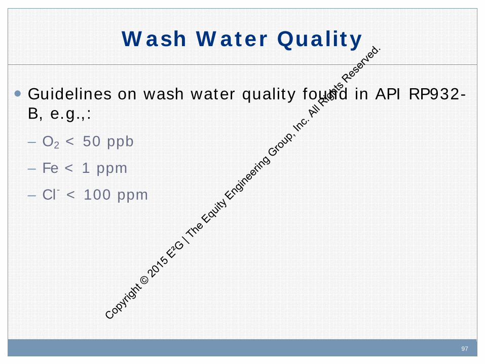
Wash Water Quality
Guidelines on wash water quality found in API RP932-B, e.g.,:
– O2 < 50 ppb
– Fe < 1 ppm
– Cl- < 100 ppm
Copyri
ght ©
2015
E²G
| The
Equ
ity E
ngine
ering
Grou
p, Inc
. All R
ights
Reserv
ed.

98 98
Materials of Construction
CS
1.25Cr-0.5Mo
2.25Cr-1Mo
Enhanced CrMo’s e.g., 3%Cr
Austenitic stainless steels, e.g., 304, 304L, 321, 347
Duplex SS
Ferritic Stainless Steels, e.g., 410S, 405
Copyri
ght ©
2015
E²G
| The
Equ
ity E
ngine
ering
Grou
p, Inc
. All R
ights
Reserv
ed.

99 99
Primary Damage Mechanisms
HTHA H2/H2S Corrosion Wet H2S Corrosion (HIC / SOHIC) Ammonium Bisulfide Ammonium Chloride Temper Embrittlement Polythionic Acid Stress Corrosion Cracking (PASCC) Chloride SCC Wash Water Injection Point Corrosion
Copyri
ght ©
2015
E²G
| The
Equ
ity E
ngine
ering
Grou
p, Inc
. All R
ights
Reserv
ed.

100
Copyri
ght ©
2015
E²G
| The
Equ
ity E
ngine
ering
Grou
p, Inc
. All R
ights
Reserv
ed.
101
API RP 571 Overview: Damage Mechanisms in the
Refining Industry
Ammonium Bisulfide (NH4HS)
Sour Water Corrosion
Copyri
ght ©
2015
E²G
| The
Equ
ity E
ngine
ering
Grou
p, Inc
. All R
ights
Reserv
ed.
102 102
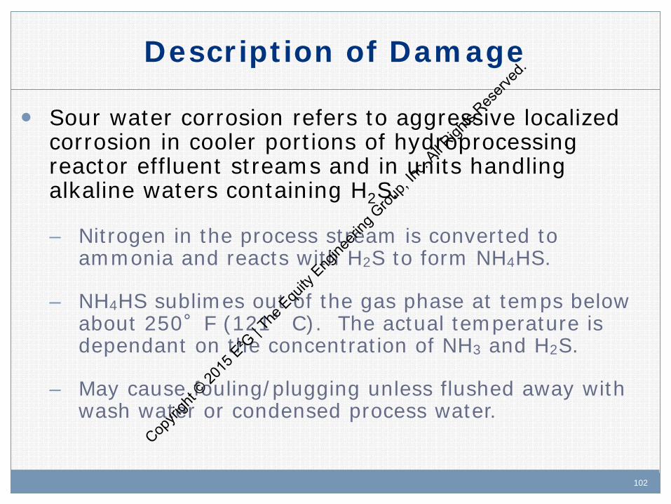
Description of Damage
Sour water corrosion refers to aggressive localized corrosion in cooler portions of hydroprocessing reactor effluent streams and in units handling alkaline waters containing H2S.
– Nitrogen in the process stream is converted to ammonia and reacts with H2S to form NH4HS.
– NH4HS sublimes out of the gas phase at temps below about 250°F (121°C). The actual temperature is dependant on the concentration of NH3 and H2S.
– May cause fouling/plugging unless flushed away with wash water or condensed process water.
Copyri
ght ©
2015
E²G
| The
Equ
ity E
ngine
ering
Grou
p, Inc
. All R
ights
Reserv
ed.

103 103
Affected Materials
CS - most commonly used in this service due to low operating temperatures.
300 Series SS.
Duplex SS.
Alloy 825, Alloy 625 and other high nickel alloys -very resistant.
Copyri
ght ©
2015
E²G
| The
Equ
ity E
ngine
ering
Grou
p, Inc
. All R
ights
Reserv
ed.

104 104
Critical Factors
Critical factors include NH4HS concentration, velocity and/or localized turbulence /wall shear stress, temperature, and flow distribution.
NH4HS Concentration: Historical “rules of thumb” -- Corrosion increases with increasing NH4HS concentration and increasing velocity.
– At < 2 wt%, solutions are not generally corrosive. CS typical.
– Above 2 wt%, solutions are increasingly corrosive. Velocity controls with CS important.
– Above 8 wt %, corrosion of CS expected to be severe. Alloys normally required.
Cop
yrigh
t © 20
15 E
²G | T
he E
quity
Eng
ineeri
ng G
roup,
Inc. A
ll Righ
ts Res
erved
.

105 105
Critical Factors
Velocity: Limit flow in CS piping to 20 fps (6 mps) maximum.
Temperature: Deposits occur below the NH4Cl deposition temperature. If below the water dewpoint, salts are typically flushed away by condensed process water so solid salt deposits may not be observed.
Wash water flow distribution: Uniform distribution critical to ensure adequate dilution and flushing of salts.
Copyri
ght ©
2015
E²G
| The
Equ
ity E
ngine
ering
Grou
p, Inc
. All R
ights
Reserv
ed.

106 106
Affected Units or Equipment
Hydroprocessing Units - Critical areas include:
– Inlet and outlet piping of air coolers (REAC) and condensers.
– Air cooler header boxes and tubes (also S&T HX).
– Sour water draw piping from reactor effluent separators; flashing may cause severe erosion-corrosion downstream of control valves.
– Vapor line from the high pressure separators (if water condenses prior to desired point).
– HC lines from reactor effluent separators due to entrained sour water.
– Stripper Column overhead. Copyri
ght ©
2015
E²G
| The
Equ
ity E
ngine
ering
Grou
p, Inc
. All R
ights
Reserv
ed.
107 107
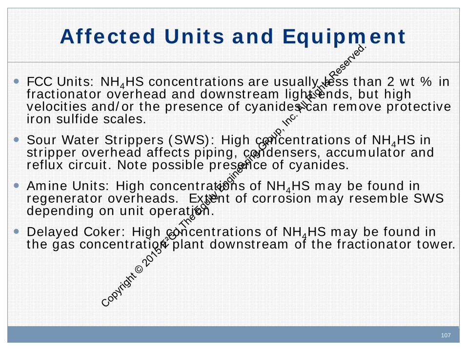
Affected Units and Equipment
FCC Units: NH4HS concentrations are usually less than 2 wt % in fractionator overhead and downstream light ends, but high velocities and/or the presence of cyanides can remove protective iron sulfide scales.
Sour Water Strippers (SWS): High concentrations of NH4HS in stripper overhead affects piping, condensers, accumulator and reflux circuit. Note possible presence of cyanides.
Amine Units: High concentrations of NH4HS may be found in regenerator overheads. Extent of corrosion may resemble SWS depending on unit operation.
Delayed Coker: High concentrations of NH4HS may be found in the gas concentration plant downstream of the fractionator tower.
Copyri
ght ©
2015
E²G
| The
Equ
ity E
ngine
ering
Grou
p, Inc
. All R
ights
Reserv
ed.

108 108
Appearance or Morphology of Damage
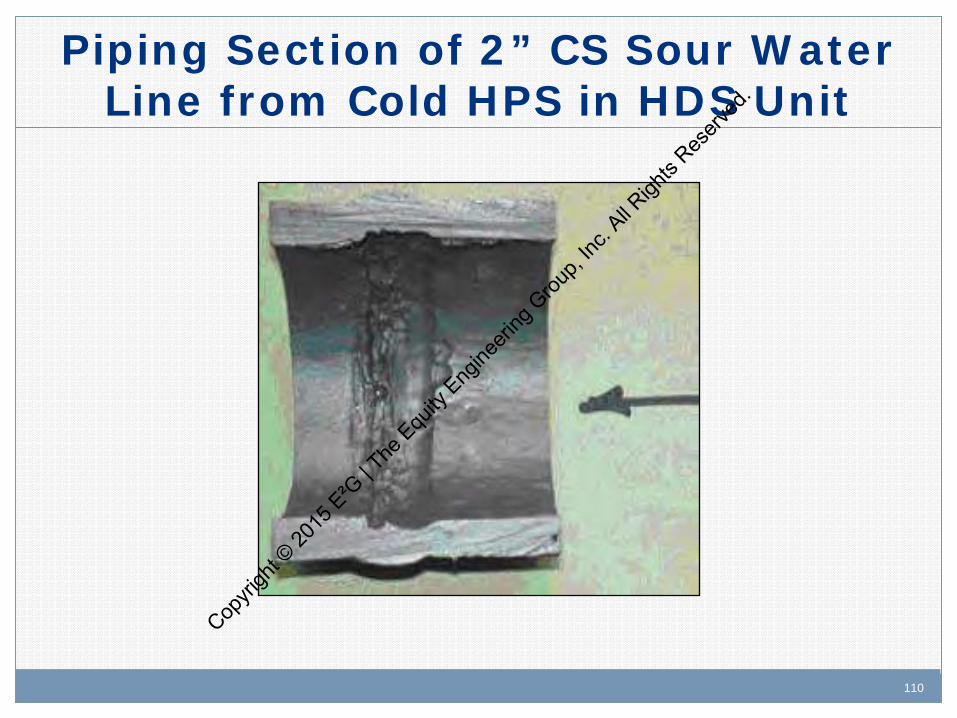
General loss in thickness of CS with the potential for extremely high localized rates of wall loss at changes in direction or turbulent flow areas with >2 wt % concentration.
Localized under-deposit corrosion if insufficient water is available to dissolve the NH4HS salts.
Heat exchangers may show plugging or loss of duty from fouling.
Copyri
ght ©
2015
E²G
| The
Equ
ity E
ngine
ering
Grou
p, Inc
. All R
ights
Reserv
ed.

109 109
2” CS Elbow in Sour Water Line from Cold HPS in HDS Unit
Copyri
ght ©
2015
E²G
| The
Equ
ity E
ngine
ering
Grou
p, Inc
. All R
ights
Reserv
ed.
110 110
Piping Section of 2” CS Sour Water Line from Cold HPS in HDS Unit
Copyri
ght ©
2015
E²G
| The
Equ
ity E
ngine
ering
Grou
p, Inc
. All R
ights
Reserv
ed.
111 111
Prevention/Mitigation
Good design practice with symmetrical and hydraulically balanced flow in and out of air coolers.
Monitor for change in process conditions, e.g., flow velocities, particularly as the NH4HS concentration exceeds 2 wt% for CS and begins to approach 8 wt %.
Maintain velocities within industry guideline of 20 fps (6 mps) maximum for CS. CS may be susceptible to high corrosion rates at higher velocities.
Copyri
ght ©
2015
E²G
| The
Equ
ity E
ngine
ering
Grou
p, Inc
. All R
ights
Reserv
ed.

112 112
Prevention/Mitigation
Use resistant materials of construction (e.g. Alloy 825, Alloy 625) at velocities > 20 fps (6 mps) depending on NH4HS concentration. – Titanium and Alloy C276 have been used in overhead condensers in
SWS units. – Aluminum also used in some SWS. Exchanger tubes are extremely
susceptible to erosion-corrosion damage.
Properly design wash water distribution system. – Symmetrical HX design important. – Use injection spray nozzles, flow control and appropriate metallurgy. – Maintain water wash injection with low O2 content. – Provide excess water to ensure adequate dilution. Target for 25%
excess water. Cop
yrigh
t © 20
15 E
²G | T
he E
quity
Eng
ineeri
ng G
roup,
Inc. A
ll Righ
ts Res
erved
.
113 113
Inspection and Monitoring
Inspection: – Plans should include input from process and materials/corrosion
engineers to determine specific areas of vulnerability. – UT scanning and/or RT profile thickness of high velocity areas. – UT / RT downstream of control valves at high NH4HS concentrations. – IRIS, RFEC and flux leakage inspection of CS finfan tubes. – Eddy Current (EC) inspect non-magnetic finfan tubes.
Operations: – Determine NH4HS content through sampling and/or calculation. – Monitor water injection facilities and flow meters to ensure proper
operation.
Copyri
ght ©
2015
E²G
| The
Equ
ity E
ngine
ering
Grou
p, Inc
. All R
ights
Reserv
ed.

114 114
Key References
API RP 932-B Design, Materials, Fabrication, Operation and Inspection Guidelines for Corrosion Control in Hydroprocessing Reactor Effluent Air Cooler (REAC) Systems.
Copyri
ght ©
2015
E²G
| The
Equ
ity E
ngine
ering
Grou
p, Inc
. All R
ights
Reserv
ed.

115
Copyri
ght ©
2015
E²G
| The
Equ
ity E
ngine
ering
Grou
p, Inc
. All R
ights
Reserv
ed.
116
API RP 571 Overview: Damage Mechanisms in the
Refining Industry
High Temperature Hydrogen Attack
(HTHA)
Copyri
ght ©
2015
E²G
| The
Equ
ity E
ngine
ering
Grou
p, Inc
. All R
ights
Reserv
ed.
117 117
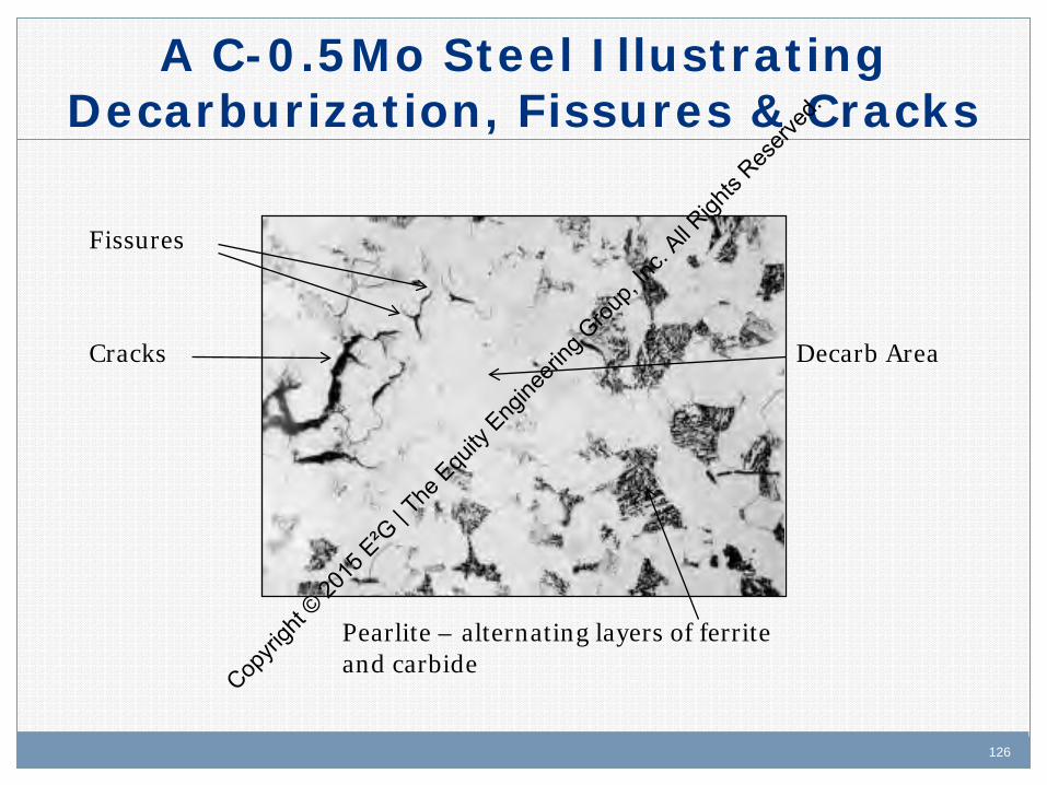
Description of Damage • HTHA refers to decarburization, fissuring and cracking
resulting from exposure to hydrogen at elevated temperatures and pressures. – H reacts with carbides in steel to form methane, CH4,
which cannot diffuse out of the steel.
– The loss of carbide causes an overall loss in strength and methane causes internal stress (very similar to creep).
– Methane pressure builds up, forming bubbles or cavities, microfissures and finally fissures that combine to form cracks.
– Failure occur when the cracks reduce the load carrying ability of the component.
Copyri
ght ©
2015
E²G
| The
Equ
ity E
ngine
ering
Grou
p, Inc
. All R
ights
Reserv
ed.
118 118
Affected Materials
CS
C-0.5Mo, Mn-0.5Mo
1Cr, 1.25Cr
2.25Cr
Copyri
ght ©
2015
E²G
| The
Equ
ity E
ngine
ering
Grou
p, Inc
. All R
ights
Reserv
ed.
119 119
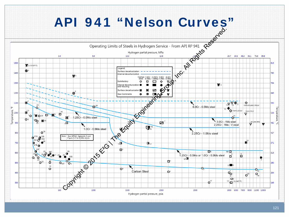
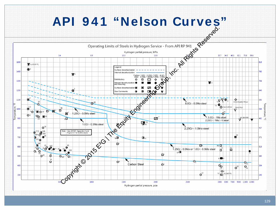
Critical Factors
• For specific material, HTHA f (temperature/hydrogen partial pressure/time/stress). − Higher temperatures generally more severe. − A temperature/hydrogen partial pressure safe operating envelope for
carbon and low alloy steels based on experience is found in ARI RP 941. These are referred to as the “Nelson Curves”.
− Service exposure time is cumulative. − Attack typically slow, appears to have incubation period before
properties are affected. May vary from hours to many years depending on operating conditions.
− Typically, both base metals and HAZ are affected. • 300 Series SS, as well as 5, 9, and 12 Cr alloys, are not susceptible
to HTHA at conditions normally seen in refinery units.
Copyri
ght ©
2015
E²G
| The
Equ
ity E
ngine
ering
Grou
p, Inc
. All R
ights
Reserv
ed.
120 120
What is Partial Pressure?
Partial Pressure = that part of the total pressure exerted by each component in a gaseous mixture. The effective partial pressure depends on the amount of the component (e.g., H2 gas) in the mixture.
Copyri
ght ©
2015
E²G
| The
Equ
ity E
ngine
ering
Grou
p, Inc
. All R
ights
Reserv
ed.
121 121
API 941 “Nelson Curves”
Copyri
ght ©
2015
E²G
| The
Equ
ity E
ngine
ering
Grou
p, Inc
. All R
ights
Reserv
ed.

122 122
Affected Units or Equipment
Hydroprocessing units, such as hydrotreaters (desulfurizers) and hydrocrackers.
Catalytic reformers. Hydrogen plants/pressure swing absorption units.
Copyri
ght ©
2015
E²G
| The
Equ
ity E
ngine
ering
Grou
p, Inc
. All R
ights
Reserv
ed.

123 123
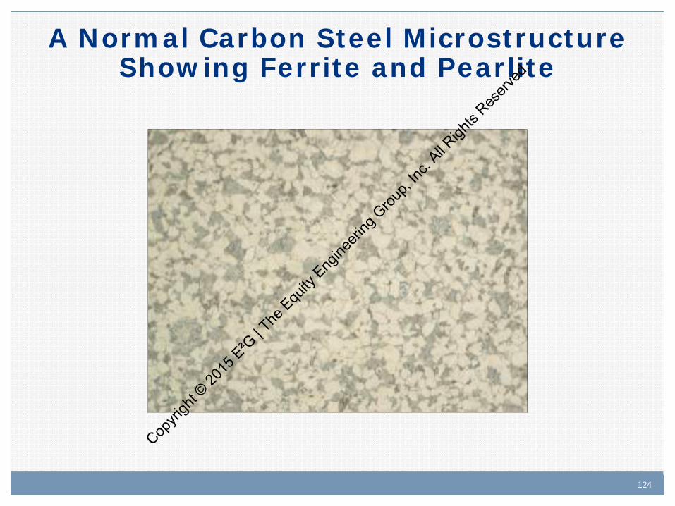
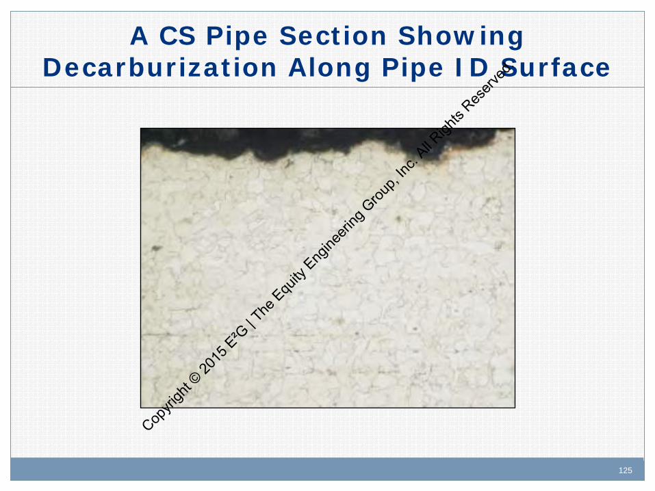
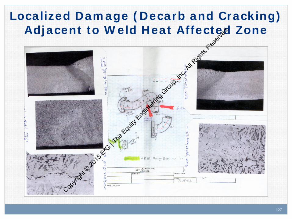
Appearance or Morphology of Damage
Damage moves from ID through the wall. Surface decarburization often observed. Early stages of damage (bubbles / voids) can be
detected with scanning electron microscopy (SEM) 15,000X. May resemble creep damage.
Advanced stages (fissuring and cracking) can be found by metallography. The damage is typically intergranular.
In rare cases, blisters are observed.
Copyri
ght ©
2015
E²G
| The
Equ
ity E
ngine
ering
Grou
p, Inc
. All R
ights
Reserv
ed.
124 124
A Normal Carbon Steel Microstructure Showing Ferrite and Pearlite
Copyri
ght ©
2015
E²G
| The
Equ
ity E
ngine
ering
Grou
p, Inc
. All R
ights
Reserv
ed.
125 125
A CS Pipe Section Showing Decarburization Along Pipe ID Surface
Copyri
ght ©
2015
E²G
| The
Equ
ity E
ngine
ering
Grou
p, Inc
. All R
ights
Reserv
ed.
126 126
A C-0.5Mo Steel Illustrating Decarburization, Fissures & Cracks
Fissures
Decarb Area
Pearlite – alternating layers of ferrite and carbide
Cracks
Copyri
ght ©
2015
E²G
| The
Equ
ity E
ngine
ering
Grou
p, Inc
. All R
ights
Reserv
ed.
127 127
Localized Damage (Decarb and Cracking) Adjacent to Weld Heat Affected Zone
Copyri
ght ©
2015
E²G
| The
Equ
ity E
ngine
ering
Grou
p, Inc
. All R
ights
Reserv
ed.
128 128
Prevention/Mitigation
Use alloy steels with higher levels of Cr and Mo to increase carbide stability. – Note C-0.5 Mo design curve was eliminated in 1990 4th
Edition of API 941 and should not be used for new equipment.
Add a safety factor of 25-50°F (14-28°C) to temperature during design.
300 Series SS overlay and/or roll bond clad material will reduce the pp H2; not used in design, but for inspection/FFS.
Copyri
ght ©
2015
E²G
| The
Equ
ity E
ngine
ering
Grou
p, Inc
. All R
ights
Reserv
ed.
129 129
API 941 “Nelson Curves”
Copyri
ght ©
2015
E²G
| The
Equ
ity E
ngine
ering
Grou
p, Inc
. All R
ights
Reserv
ed.

130 130
Inspection and Monitoring Inspection
– Advanced stages of damage in many cases appear to be localized, challenging the ability of inspection.
– Ultrasonic techniques (AUBT) consisting of a combination of backscatter, velocity ratio, and spectral analysis have been the most successful in finding fissuring and/or serious cracking.
– FMR can only detect fissuring and decarburization near the surface. Most equipment has decarburized surfaces due to the various heat treatments used during fabrication. Selective sample removal may be an option.
– VT for blisters on ID may indicate potential HTHA, but HTHA does not require blisters.
Operations: – Be aware of process creep that can result in higher operating
temperatures. Cop
yrigh
t © 20
15 E
²G | T
he E
quity
Eng
ineeri
ng G
roup,
Inc. A
ll Righ
ts Res
erved
.

131 131
Miniature Sample for HTHA Analysis
Copyri
ght ©
2015
E²G
| The
Equ
ity E
ngine
ering
Grou
p, Inc
. All R
ights
Reserv
ed.
132 132
Key References
API RP 941 – Steels for Hydrogen Service at Elevated Temperatures and Pressures in Petroleum Refineries and Petrochemical Plants
Copyri
ght ©
2015
E²G
| The
Equ
ity E
ngine
ering
Grou
p, Inc
. All R
ights
Reserv
ed.

133
Copyri
ght ©
2015
E²G
| The
Equ
ity E
ngine
ering
Grou
p, Inc
. All R
ights
Reserv
ed.
134
API RP 571 Overview: Damage Mechanisms in the
Refining Industry
Influence of Damage Mechanisms on
Current Initiatives Copyri
ght ©
2015
E²G
| The
Equ
ity E
ngine
ering
Grou
p, Inc
. All R
ights
Reserv
ed.

135 135
Current Initiatives
Risk Based Inspection (RBI) Integrity Operating Windows (IOWs) Fitness for Service (FFS) Fixed Equipment Mechanical Integrity (FEMI)
Copyri
ght ©
2015
E²G
| The
Equ
ity E
ngine
ering
Grou
p, Inc
. All R
ights
Reserv
ed.

136 136
Risk Based Inspection (RBI)
API 580/581 – Risk Based Inspection/ Risk Based Inspection Technology, Second Editions 11/2009 & 9/2008
Evaluate equipment’s ability to resist relevant damage mechanisms over a specified interval
Risk determined based on assumptions of future operation
RBI used to develop effective inspection plans to mitigate risk to an acceptable level
Copyri
ght ©
2015
E²G
| The
Equ
ity E
ngine
ering
Grou
p, Inc
. All R
ights
Reserv
ed.

137 137
RBI/Damage Mechanisms
Crude/Vacuum Unit – Sulfidation: Damage uniform. Enables prediction of
remaining life through measured or estimated corrosion rates.
– Naphthenic acid: Damage localized. Assessment is subjective with reliance on experience.
– Ammonium chloride: Damage localized. Assessment is subjective with reliance on experience.
Copyri
ght ©
2015
E²G
| The
Equ
ity E
ngine
ering
Grou
p, Inc
. All R
ights
Reserv
ed.
138 138
RBI/Damage Mechanisms
Hydroprocessing – Ammonium Bisulfide: Damage localized. Assessment is
subjective with reliance on experience – HTHA: Damage localized. RBI best suited for high level
screening rather than typical assessment. Will likely require detailed engineering review outside of the RBI study to better quantify damage potential
Copyri
ght ©
2015
E²G
| The
Equ
ity E
ngine
ering
Grou
p, Inc
. All R
ights
Reserv
ed.
139 139
Integrity Operating Windows (IOWs)
API 584 Integrity Operating Windows, First Edition May 2014
IOWs intended to place limits on those variables that directly influence corrosion
Knowledge of existing damage mechanisms critical in setting limits – Limits influenced by materials of construction – Unit operations
Feeds into overall mechanical integrity program for vessels and piping
Copyri
ght ©
2015
E²G
| The
Equ
ity E
ngine
ering
Grou
p, Inc
. All R
ights
Reserv
ed.

140 140
Integrity Operating Windows (IOWs)
Note: If they are already established at the time of RBI implementation, IOWs can be used to: – Protect the integrity of the RBI analysis by ensuring that
assumptions, e.g. temperature and sulfur content, remain valid
– Alert FE stakeholders if the RBI premise has been violated which might require changes to the inspection plan
Copyri
ght ©
2015
E²G
| The
Equ
ity E
ngine
ering
Grou
p, Inc
. All R
ights
Reserv
ed.
141 141
IOWs/Damage Mechanisms
Crude/Vacuum Unit -typical IOW controls include: – Sulfidation Feed and stream sulfur levels Operating temperatures
– Naphthenic Acid TAN in feed and relevant bottoms and side streams Sulfur in feed and relevant bottoms and side streams
– Ammonium Chloride Salt deposition temperature Wash water injection rates
Copyri
ght ©
2015
E²G
| The
Equ
ity E
ngine
ering
Grou
p, Inc
. All R
ights
Reserv
ed.

142 142
IOWs/Damage Mechanisms
Hydroprocessing – typical IOW controls include: – Ammonium Bisulfide Concentration of NH4HS Velocity (wall shear stress) Wash water injection rates
– HTHA Operating temperature Hydrogen partial pressure
Copyri
ght ©
2015
E²G
| The
Equ
ity E
ngine
ering
Grou
p, Inc
. All R
ights
Reserv
ed.

143 143
Fitness for Service (FFS)
API 579 Fitness for Service, 2nd Edition 6/2007. FFS provides methodology to evaluate existing
damage to determine if component is suitable for continued service.
Must understand the damage mechanism that created the problem and how damage will progress.
Assessments address various DM including general thinning, localized thinning, pitting, brittle fracture, blistering, etc.
Copyri
ght ©
2015
E²G
| The
Equ
ity E
ngine
ering
Grou
p, Inc
. All R
ights
Reserv
ed.
144 144
Fitness for Service/Damage Mechanisms
Crude/Vacuum Unit – Sulfidation: general thinning – Naphthenic acid: local thinning – Ammonium chloride: pitting
Hydroprocessing – Ammonium Bisulfide: local thinning – HTHA: not well addressed by current technology, but
methodologies being developed
Copyri
ght ©
2015
E²G
| The
Equ
ity E
ngine
ering
Grou
p, Inc
. All R
ights
Reserv
ed.
145 145
Fixed Equipment Incident Investigation
API 585 – Pressure Equipment Integrity Incident Investigation, First Edition April 2014
Must understand damage mechanisms to: – Identify factors contributing to failure, – Recommend effective solutions, – Modify inspection plans.
Copyri
ght ©
2015
E²G
| The
Equ
ity E
ngine
ering
Grou
p, Inc
. All R
ights
Reserv
ed.

146 146
Summary
Industry documents and practices dealing with mechanical integrity of refining equipment (e.g., IOWs, RBI, FFS)place heavy reliance on understanding damage mechanisms.
API 571 provides guidance on the DM influencing refining equipment and directly supports the FEMI initiative
Copyri
ght ©
2015
E²G
| The
Equ
ity E
ngine
ering
Grou
p, Inc
. All R
ights
Reserv
ed.

147
Shaker Heights, OH Houston, TX Victoria, TX
Alberta, Canada Abu Dhabi, UAE
www.equityeng.com
Copyri
ght ©
2015
E²G
| The
Equ
ity E
ngine
ering
Grou
p, Inc
. All R
ights
Reserv
ed.