residential oil hydronic heating system -...
TRANSCRIPT
Homeowner’s Book And Installation Manual QXM8 Series
Models : QXM8-065F1-OL/085F1-OL/120F1-OL/150F1-OLModels : QXM8-065F1-OL/085F1-OL/120F1-OL/150F1-OLModels : QXM8-065F1-OL/085F1-OL/120F1-OL/150F1-OLModels : QXM8-065F1-OL/085F1-OL/120F1-OL/150F1-OL
QXW8-120F1-OL QXW8-120F1-OL QXW8-120F1-OL QXW8-120F1-OL
RReessiiddeennttiiaall OOiill HHyyddrroonniicc HHeeaattiinngg SSyysstteemm
COMFORMS TO UL-732
COMFORMS TO CSA B140.3-R1998
Residential Residential Residential Residential Oil Oil Oil Oil Hydronic Heating SystemHydronic Heating SystemHydronic Heating SystemHydronic Heating System
QXM8QXM8QXM8QXM8 SeriesSeriesSeriesSeries 2222
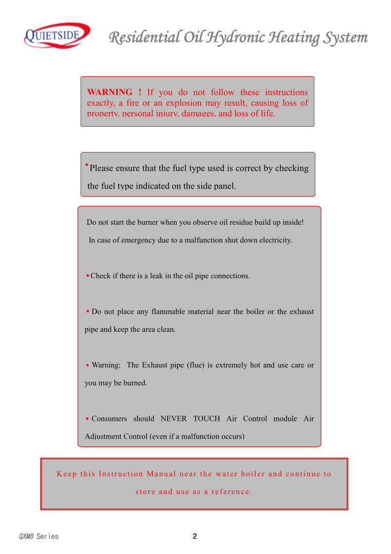
K e e p t h i s In s t r u c t i on M a nu a l n e a r t h e wa t e r b o i l e r an d c o n t i n u e t o
s to r e a nd u s e as a r e f e re n c e .
WARNING ! If you do not follow these instructionsexactly, a fire or an explosion may result, causing loss ofproperty, personal injury, damages, and loss of life.
Please ensure that the fuel type used is correct by checking
the fuel type indicated on the side panel.
Do not start the burner when you observe oil residue build up inside!
In case of emergency due to a malfunction shut down electricity.
Check if there is a leak in the oil pipe connections.
Do not place any flammable material near the boiler or the exhaust
pipe and keep the area clean.
Warning: The Exhaust pipe (flue) is extremely hot and use care or
you may be burned.
Consumers should NEVER TOUCH Air Control module Air
Adjustment Control (even if a malfunction occurs)
Residential Residential Residential Residential Oil Oil Oil Oil Hydronic Heating SystemHydronic Heating SystemHydronic Heating SystemHydronic Heating System
3333 QXM8QXM8QXM8QXM8 Series Series Series Series
The printed material or words in red are related to yoursafey. Please read carefully before starting the systeminstallation and operation.
▣ Please read through this informative manual
and pay special attention to the following:● Identifying the Components · · · · · · · · · · · · · 4
● Safety Issues · · · · · · · · · · · · · · · · · · 7
● Advantages of QXM8 Hydronic Heating System · · · · · · 10
● Needs to be later in manual after installation · · · · · · · · · 13
● Instal lat ion · · · · · · · · · · · · · · · · · · 14
● Oil Piping Connections · · · · · · · · · · · · · · 18
● I ns t a l l a t ion o f t he F lue · · · · · · · · · · · · · 1 9
● Hydronic Ins ta l la t io n · · · · · · · · · · · · · · 22
● Using The Thermostat · · · · · · · · · · · · · · · · 28
● Routine Maintenance · · · · · · · · · · · · · · · · 34
● Dimensional Drawing of the Unit · · · · · · · · · · 35
● Wiring Diagrams · · · · · · · · · · · · · · · · · 38
● Troubleshooting · · · · · · · · · · · · · · · · · 40
● Exploded Views · · · · · · · · · · · · · · · · · 41
● Parts List· · · · · · · · · · · · · · · · · · · · 46
● Specificat ions · · · · · · · · · · · · · · · · · 51
QX
M8
QX
M8
QX
M8
QX
M8,
QX
W8
Seri
es,Q
XW
8 Se
ries
,QX
W8
Seri
es,Q
XW
8 Se
ries
for buying this QUIETSIDE hydronic heating system to use it
Please read this manual carefully before installing and operating the boiler
Residential Residential Residential Residential Oil Oil Oil Oil Hydronic Heating SystemHydronic Heating SystemHydronic Heating SystemHydronic Heating System
QXM8QXM8QXM8QXM8 SeriesSeriesSeriesSeries 4444
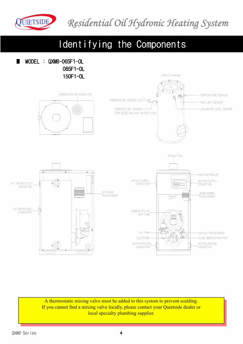
Identifying the ComponentsIdentifying the ComponentsIdentifying the ComponentsIdentifying the Components
A thermostatic mixing valve must be added to this system to prevent scalding.If you cannot find a mixing valve locally, please contact your Quietside dealer or
local specialty plumbing supplier.
■■■■ M M M MODELODELODELODEL : : : : QXM8-065F1-OLQXM8-065F1-OLQXM8-065F1-OLQXM8-065F1-OL
085F1-OL 085F1-OL 085F1-OL 085F1-OL
150F1-OL 150F1-OL 150F1-OL 150F1-OL
Residential Residential Residential Residential Oil Oil Oil Oil Hydronic Heating SystemHydronic Heating SystemHydronic Heating SystemHydronic Heating System
5555 QXM8QXM8QXM8QXM8 Series Series Series Series
Identifying the ComponentsIdentifying the ComponentsIdentifying the ComponentsIdentifying the Components
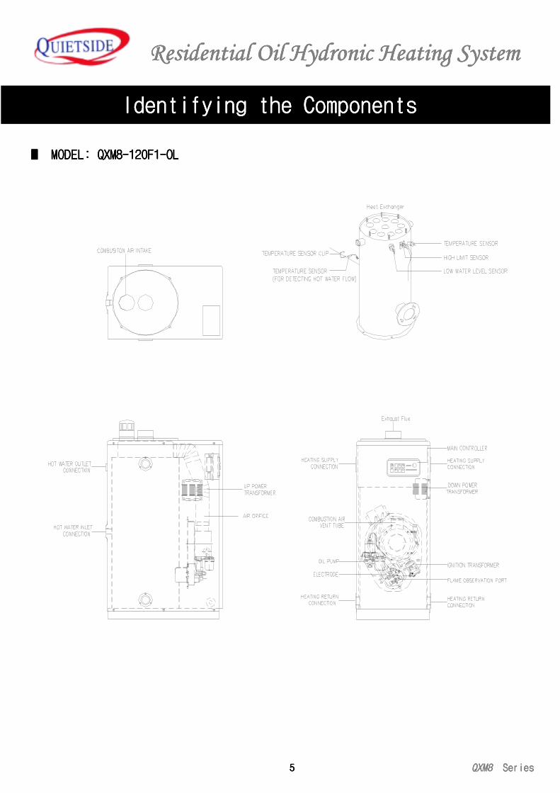
■■■■ M M M MODELODELODELODEL: : : : QXM8-120F1-OLQXM8-120F1-OLQXM8-120F1-OLQXM8-120F1-OL
Residential Residential Residential Residential Oil Oil Oil Oil Hydronic Heating SystemHydronic Heating SystemHydronic Heating SystemHydronic Heating System
QXM8QXM8QXM8QXM8 SeriesSeriesSeriesSeries 6666
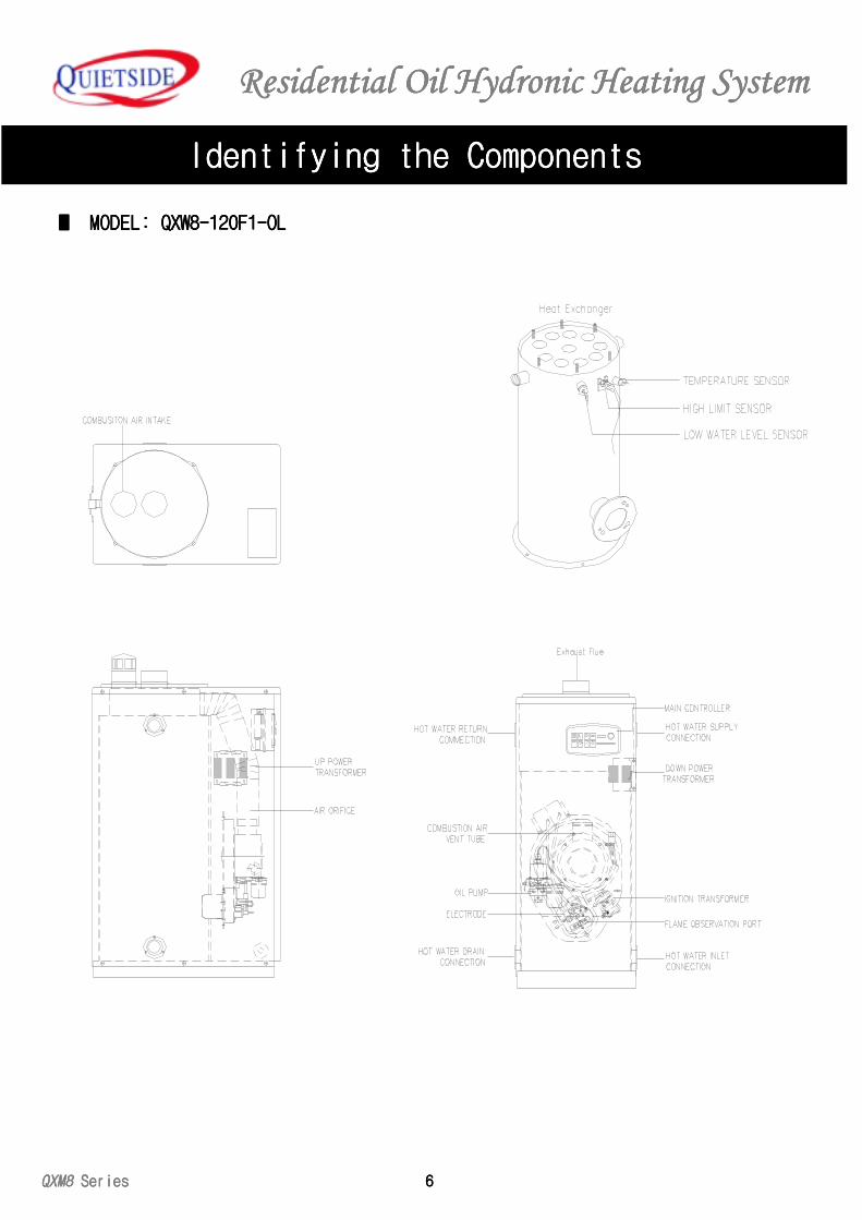
■■■■ M M M MODELODELODELODEL: : : : QXW8-120F1-OLQXW8-120F1-OLQXW8-120F1-OLQXW8-120F1-OL
Identifying the ComponentsIdentifying the ComponentsIdentifying the ComponentsIdentifying the Components
Residential Residential Residential Residential Oil Oil Oil Oil Hydronic Heating SystemHydronic Heating SystemHydronic Heating SystemHydronic Heating System
7777 QXM8QXM8QXM8QXM8 Series Series Series Series
Safety IssuesSafety IssuesSafety IssuesSafety Issues
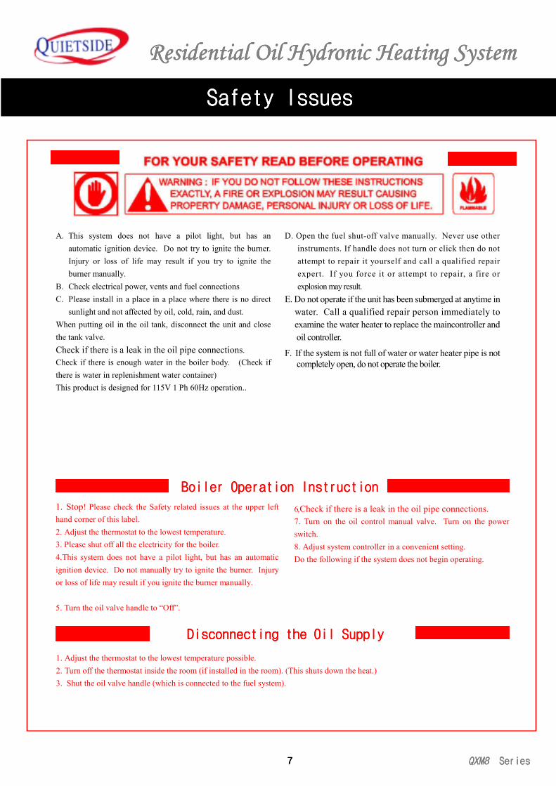
A. This system does not have a pilot light, but has anautomatic ignition device. Do not try to ignite the burner.Injury or loss of life may result if you try to ignite theburner manually.
B. Check electrical power, vents and fuel connectionsC. Please install in a place in a place where there is no direct
sunlight and not affected by oil, cold, rain, and dust.When putting oil in the oil tank, disconnect the unit and closethe tank valve.Check if there is a leak in the oil pipe connections.Check if there is enough water in the boiler body. (Check ifthere is water in replenishment water container)This product is designed for 115V 1 Ph 60Hz operation..
D. Open the fuel shut-off valve manually. Never use other instruments. If handle does not turn or click then do not attempt to repair it yourself and call a qualified repair expert. If you force it or attempt to repair, a fire or explosion may result.E. Do not operate if the unit has been submerged at anytime in water. Call a qualified repair person immediately to examine the water heater to replace the maincontroller and oil controller.
F. If the system is not full of water or water heater pipe is not completely open, do not operate the boiler.
Boiler Operation InstructionBoiler Operation InstructionBoiler Operation InstructionBoiler Operation Instruction
1. Stop! Please check the Safety related issues at the upper lefthand corner of this label.2. Adjust the thermostat to the lowest temperature.3. Please shut off all the electricity for the boiler.4.This system does not have a pilot light, but has an automaticignition device. Do not manually try to ignite the burner. Injuryor loss of life may result if you ignite the burner manually. 5. Turn the oil valve handle to “Off”.
6, Check if there is a leak in the oil pipe connections.7. Turn on the oil control manual valve. Turn on the powerswitch.8. Adjust system controller in a convenient setting.Do the following if the system does not begin operating.
Disconnecting the Disconnecting the Disconnecting the Disconnecting the Oil SupplyOil SupplyOil SupplyOil Supply
1. Adjust the thermostat to the lowest temperature possible.2. Turn off the thermostat inside the room (if installed in the room). (This shuts down the heat.)3. Shut the oil valve handle (which is connected to the fuel system).
Residential Residential Residential Residential Oil Oil Oil Oil Hydronic Heating SystemHydronic Heating SystemHydronic Heating SystemHydronic Heating System
QXM8QXM8QXM8QXM8 SeriesSeriesSeriesSeries 8888
Safety IssuesSafety IssuesSafety IssuesSafety Issues
1. Ignition failureIf the boiler ignition fails, the oil supply will be automatically
shut down. The inspection light on the indoor thermostat andboiler control will light up.
2. Fire DetectionIf the first ignition fails and subsequent attempt also fails, then
oil supply will be automatically shut down. The inspection lighton the indoor thermostat and boiler control will light up.
3. Power InterruptionInterruptionInterruptionInterruption If power was disconnected for at least two hours thenrestart the boiler by using the Turbo button.
4. Overheat ProtectionOverheat ProtectionOverheat ProtectionOverheat ProtectionWhen heat reciprocator is overheated then the oil supplywill shut down. The inspection light on the indoor thermostatand boiler control will light up. Press the reset button to re-start the boiler.
5, 5, 5, 5, Low Water-Level SafetyLow Water-Level SafetyLow Water-Level SafetyLow Water-Level Safety Check hot water level periodically to prevent water flowproblems and dry pipes. In such cases, the system operationwill automatically terminate and The inspection light on theindoor thermostat and boiler control will light up.
6. Freeze ProtectionProtectionProtectionProtectionDuring the winter months an internal sensor system willautomatically detect low water temperature and prevent freezing ofthe internal system by initiating a safety heating cycle. Warning:When oil supply ceases, a circulating pump will automatically startoperation to prevent pipes from freezing. (this is only applicable tothe models with the circulating pump fitted)
7. Short-Circuit ProtectionShort-Circuit ProtectionShort-Circuit ProtectionShort-Circuit ProtectionIf there is a short circuit inside the electrical circuit then theinternal glass fuse will blow and automatically shut down the oilsupply.
8. 8. 8. 8. Lightning ProtectionLightning ProtectionLightning ProtectionLightning ProtectionAll of our models are specially grounded to prevent lightningdamage.
9. Thermostat Control FailureThermostat Control FailureThermostat Control FailureThermostat Control FailureIf thermostat is not functioning normally, the oil supply will beautomatically shut down
10. Sticking Guard deviceWhen Boiler is not used for a long period of time, to prevent burnermotor and rotation pump sticking the device will initiate operationevery 24hours for 30 seconds. (Do not disconnect the unit or thisfeature will not operate.)
Device Safety and Physical safety Device Safety and Physical safety Device Safety and Physical safety Device Safety and Physical safety
Residential Residential Residential Residential Oil Oil Oil Oil Hydronic Heating SystemHydronic Heating SystemHydronic Heating SystemHydronic Heating System
9999 QXM8QXM8QXM8QXM8 Series Series Series Series
Safety IssuesSafety IssuesSafety IssuesSafety Issues
During the winter, to prevent freezing, do not disconnect the unit.Other than heating or for hot water, DO NOT USE the unit for dryinglaundry, cooking, and other purposes, or a fire may result.Check if there is any oil leak or oil seepage in the oil tank, oil pipe, and boiler(inside and outside).Have the system checked annually by a professional inspector. This willensure proper maintenance and prolong long life and efficient operation of thesystem.
Only use the oil type prescribed on the side panel of the OUIETSIDE Boiler.Do not touch the unit with wet hands. Do not clean the unit by pouring waterdirectly into it. This may cause electric shock.
Residential Oil Hydronic Heating SystemResidential Oil Hydronic Heating SystemResidential Oil Hydronic Heating SystemResidential Oil Hydronic Heating System
QXM8 Series 10
THE QXM8QUIETSIDE VARIABLE-CAPACITY, MULTI-PURPOSE
80%+ HYDRONIC HEATING SYSTEM
This product is a heating and domestic hot water supply system. QXM8 Boiler has two independently operating unique hotwater heating functions. First is the heating function. Hot water at a high temperature is circulated through a radiator,radiator panel, or a fancoil unit for heating the home. This boiler solves all your family’s heating needs for the winter. Thesecond feature is the domestic hot water supply for the home. This water can be used for bath, shower, dishes, and laundry.When using QXM8 for domestic hot water, the system will operate as a ‘Super water heater’ to provide for all your hot waterneeds. (Water heating will stop only when you shut down the hot water valve or faucet.) The heating water for the home andthe circuit for heating domestic water operate independently and have two different temperature ranges.
The water temperature of the domestic hot wateris not set at the factory. This temperature can attain a maximum of 176DegF. A MIXING VALVE MUST BE FITTED TO THE SYSTEM TO PREVENT BURNS AND SCALDS. Please beadvised again that adjustment valve selection is the customer’s choice. Please consult with QUIETSIDE dealer or with aqualified contractor for more details.
Thermostats
The Roomcon-7 is not suitable for a multipurpose system. Your QUIETSIDE Installation contractor will determine theRoomcon-7’s suitability and if it is not suitable, install an adaptor control for controlling the QUIETSIDE boiler.
In the winter months, QXM8 will place first priority in household water heating than for heating the house. If you turn on ahot water faucet anywhere in the house, the water for heating will be diverted to heat the domestic hot water. When the hotwater faucet is turned off, boiler will again revert to the heating mode. (This is the same priority in the summer.)
This boiler has a special stainless steel exhaust system called SCF-8. This promotes efficient heating and a cleaner exhaustsystem inside the boiler. First, the combustion air blower pulls air directly from the outside via the air intake and delivers it tothe heat exchanger. This process minimizes carbon monoxide production. Exhaust gas is vented out through the exhaustchamber and through the flue to the outside. Moreover, the QUIETSIDE sealed combustion system prevents recirculation ofexhaust discharge making the, QXM8 is one of the most efficient, safe, and clean boilers in the world.
Advantages of QXM8 Hydronic Heating System
How Does My Quietside QXM8 Work?How Does My Quietside QXM8 Work?How Does My Quietside QXM8 Work?How Does My Quietside QXM8 Work?
Burns from Scalding.Burns from Scalding.Burns from Scalding.Burns from Scalding.
The Sealed-The Sealed-The Sealed-The Sealed-Combustion(flue)Venting ProcessCombustion(flue)Venting ProcessCombustion(flue)Venting ProcessCombustion(flue)Venting Process
Domestic Hot Water PriorityDomestic Hot Water PriorityDomestic Hot Water PriorityDomestic Hot Water Priority
Residential Residential Residential Residential OilOilOilOil Hydronic Heating System Hydronic Heating System Hydronic Heating System Hydronic Heating System
11 QXM8 Series
Advantages of QXM Hydronic Heating System
1. Boiler Controller (located in the Boiler Front Panel)This control device offers other control function and allows the homeowner to visually check the functional condition of the boiler.Through this control section, you may control the heating circuit water temperature independently by controlling the main heater watertemperature. Heating your house with water temperature adjustments is recommended rather than with air heating method. If youlower the water temperature (turn the knob to the left to lower and to the right to higher), boiler will use less fuel for combustion and thehouse will heat from room to room in a uniform fashion. This is appropriate for the fall or early spring season.
2. Continuous-Discharge Auto Ignition TypeContinuous-Discharge Auto Ignition TypeContinuous-Discharge Auto Ignition TypeContinuous-Discharge Auto Ignition TypeDirect ignition method to use less fuel and save money on costs.
3. Combustion Safety ProtectionIf the burner does not ignite or the flame does not stay due to oil shortage, Flame Sensor Device will completely shut downthe boiler.
4. Excessive Wind Pressure Safety ProtectionExcessive Wind Pressure Safety ProtectionExcessive Wind Pressure Safety ProtectionExcessive Wind Pressure Safety Protection When there is a power outage, oil is suppressed and the boiler shuts down automatically
1. Continuous Hot WaterContinuous Hot WaterContinuous Hot WaterContinuous Hot Water
Whenever you need hot water! Hot water is always available. The QUIETSIDE model QXM8 has an activation system toheat hot water on demand.
2. Timer ModeTimer ModeTimer ModeTimer Mode
The timer mode can save energy when no one is home. 1. Press the control device to select the program while away fromhome. 2. Press the ‘on’ button. 3. Leave. Then the machine will automatically shut down for the designated time period.Upon return, select the turbo button to enable the boiler to heat up to the set temperature quickly. Lastly, press the Winter todeactivate the program.
NOTE: Turbo mode is not recommended if you have a floor heating system since it may overheat the floor as the watertemperature is 176 DegF during this mode.
3. Continuous-Discharge Ignition (C.D.I.)Continuous-Discharge Ignition (C.D.I.)Continuous-Discharge Ignition (C.D.I.)Continuous-Discharge Ignition (C.D.I.)
QXM8,and QXW units do not use an unnecessary pilot burner, but is designed to use direct ignition to save fuel and money.4. 4. 4. 4. Combustion Safety ProtectionCombustion Safety ProtectionCombustion Safety ProtectionCombustion Safety Protection
After you press the on switch and the unit does not ignite, due to oil shortage or system malfunction problem. The automaticflame sensor shuts down the system operation.
5. 5. 5. 5. Safety Protection Safety Protection Safety Protection Safety Protection During Power OutagesDuring Power OutagesDuring Power OutagesDuring Power Outages
When power supply shorts or system switch turns off, oil supply is automatically shut down and the system is off until powersupply is restored.
6. 6. 6. 6. Proportional Temperature ControlProportional Temperature ControlProportional Temperature ControlProportional Temperature Control
This control continually analyzeses the water flow and condition along with the capacity to maintain the temperature ofheating hot water.
7. 7. 7. 7. SCF-8 Coaxial Flue Kit SCF-8 Coaxial Flue Kit SCF-8 Coaxial Flue Kit SCF-8 Coaxial Flue Kit (QXM8,QXW )
This device exhausts the combustion gases and increases by 2% of the combustion efficiency by heating the combustion airbefore it enters the unit. It is easy and convenient to install, if you just drill a hole, diameter 4-1/4” on one of the wallsadjacent to the unit. The flue is constructed from type 304 Stainless Steel for long life, and is supplied with all the necessaryconnectors and clamps.
Quietside QXM8 Product Features and FunctionsQuietside QXM8 Product Features and FunctionsQuietside QXM8 Product Features and FunctionsQuietside QXM8 Product Features and Functions
Other Features and Control FunctionsOther Features and Control FunctionsOther Features and Control FunctionsOther Features and Control Functions
Residential Oil Hydronic Heating SystemResidential Oil Hydronic Heating SystemResidential Oil Hydronic Heating SystemResidential Oil Hydronic Heating System
QXM8 Series 12
1. Burner Safety Device (Flame Detection)If flame is not ignited on the second try, oil supply is automatically shut down.
2. Safety Protection on Power RestorationSafety Protection on Power RestorationSafety Protection on Power RestorationSafety Protection on Power RestorationWhen the power comes back on, water heater will automatically activate and return to normal operation. A manual reset is not required.
3. Safety Protection for Ignition-Failure (Flame Detection)Safety Protection for Ignition-Failure (Flame Detection)Safety Protection for Ignition-Failure (Flame Detection)Safety Protection for Ignition-Failure (Flame Detection)In case of ignition failure, oil supply is automatically shut down.
4. Overheat Protection (High-Limit)Overheat Protection (High-Limit)Overheat Protection (High-Limit)Overheat Protection (High-Limit)In case of heat exchanger overheating, the oil supply is shut down and the unit automatically shuts down.
5. Low-Water Level SafetyLow-Water Level SafetyLow-Water Level SafetyLow-Water Level SafetyThe unit senses the water level in the heat exchanger, to guard against pump and heat exchanger damage in case the water level reaches adangerous level. If this happens the device shuts down the boiler operation.
6. Thermostat Safety ProtectionThermostat Safety ProtectionThermostat Safety ProtectionThermostat Safety ProtectionThe thermostat has an internal self-evaluation function. If automatic temerature control internal detector malfunctions then oil supply isautomatically shut down.
7. Freeze Protection (unit must be connected to Freeze Protection (unit must be connected to Freeze Protection (unit must be connected to Freeze Protection (unit must be connected to 120 volt power source and/or oil supply)120 volt power source and/or oil supply)120 volt power source and/or oil supply)120 volt power source and/or oil supply)When the water temperature falls to an extreme level, boiler automatically operates for a short period of time to guard againstthe danger of water freezing up, which may damage the system. When the oil supply is not connected, the circulation pumpwill operate (if fitted)
8. Short Circuit Safety ProtectionShort Circuit Safety ProtectionShort Circuit Safety ProtectionShort Circuit Safety ProtectionIn case of a short circuit, a small and exchangeable (glass) fuse blows to automatically stop the oil supply to the burner.
9. Boiling (steaming) PreventionBoiling (steaming) PreventionBoiling (steaming) PreventionBoiling (steaming) Prevention
If any malfunction or adverse effect causes internal water temperature to rise over 212o F, then the overheat warning indicator lights up aswell as automatic shut down of the boiler occurring.
10. Lightning and Static Electricity ProtectionLightning and Static Electricity ProtectionLightning and Static Electricity ProtectionLightning and Static Electricity ProtectionThe boiler is grounded inside and out to protect against static electricity and lightning.
11. Sticking Guard Device If boiler is not in operation for a prolonged period of time, the device activates the boiler for 30 seconds every 24 hours to prevent burnermotor and circulation pump from sticking (do not disconnect the unit or this safety cannot activate)
Advantages of QXM Hydronic Heating System
Operating Safety and ProtectionOperating Safety and ProtectionOperating Safety and ProtectionOperating Safety and Protection
Residential Residential Residential Residential OilOilOilOil Hydronic Heating System Hydronic Heating System Hydronic Heating System Hydronic Heating System
13 QXM8 Series
Warning: When you want to shut down the boiler for a few days, it isrecommended that you select freeze guard mode. This is moreeffective for freeze prevention. When you select this mode, do notdisconnect the boiler power source.
■ After attaching and fixing the tank shut off valve, fill the oil tank.■ Check to see if any blockage exists in the exhaust pipe and air
intake pipe. Connect the machine to 120V power source andopen the oil tank valve.
■ Ensure that the thermostat is set correctly.■ Selct hot water and heating mode. Press the power button to
initiate the operation light to come on and to activate the boilerin heating and hot water modes.
■ If hot water level is low inside the system, the “Check” indicatorlight comes on and boiler shuts down automatically. Open themanual hot water supply valve to fill the system tank. Check tomake sure manual air valve is open.
■ If “Check” light stays on and different indicators turn on at theboiler controller, call the authorized QUIETSIDE technician.
■ Set the heater temperature to match customer’s systemrequirements. (Inside the boiler control.) Set Roomcon-7thermostat to inside temperature and start the boiler.
■ When using hot water while boiler is on, space heatingautomatically shuts down and hot water is supplied to the faucet.
■ When you turn the faucet off, the unit automatically returns to heating mode.■ When using hot water without heating during other seasons, hot water will come out from the faucet.■ When using hot water without heating, press “summer” switch in the control for the most economical operation. ■ In the summer mode, the water heater does not shut off even if you turn off the faucet after using the hot water.
■ Diconnect all power to the boiler.■ Open manual drain valve to drain all the water inside the unit to prevent freezing during winter.■ Close the hot water supply valve (Inlet valve) and open one or more faucets to drain water from domestic hot water system..■ Close the Inlet oil supply valve
Needs to be later in manual after installation
Before UsingBefore UsingBefore UsingBefore Using
Notes for IgnitionNotes for IgnitionNotes for IgnitionNotes for Ignition
Shutting Down the Boiler forShutting Down the Boiler forShutting Down the Boiler forShutting Down the Boiler forProlongedProlongedProlongedProlonged PeriodsPeriodsPeriodsPeriods
Residential Oil Hydronic Heating SystemResidential Oil Hydronic Heating SystemResidential Oil Hydronic Heating SystemResidential Oil Hydronic Heating System
QXM8 Series 14
Installation
■ If the installation is done by unqualified person who is not a trained professional (in applicable cases a certified professional) , all the warranties are null and void. ■ QUIETSIDE Corporation is not responsible for problems and damage caused by a faulty installation, lack of installation ability, or failure to use manufacturer provided materials or instructions in this manual.
■ Boiler installer must provide the homeowner instructions about system operation, safety instructions, warranties, maintenance schedule, and service and repair contacts. ■ After completeing installation, installer must provide homeowner with a proper certificate of guarantee.
■ QUIETSIDE QXM8 and QXW8 Boilers have a low operation noise level and are designed to allow if required for installationin the kitchen, laundry, or bathroom.
■ The size of the boiler room must be at least 88 square feet. (example: 4ft x 9ft x 8ft).■ Do not store flammable materials or explosives near the boiler. ■ the temperature inside the boiler room, especially the floor
cannot fall below +48℉℉℉℉ or above +105℉℉℉℉ (normal airtemperature should be above +50℉℉℉℉ )
■ Boiler cannot be installed outside the house.■ Boiler must be installed on firm, flat, and non-flammable material floor.■ Take care to check the vent system to be used. The individual vent system places limitations on the location of the boiler.
This system is specially packaged and shipped to prevent damagethat can happen during the normal handling and shipment. Do notdrop or throw the boiler or it may cause serious internal damage.If you store the system horizontally damage could occur. Unitshould not be stored in locations subject to freezing as final testingprocedure leaves water inside the heat exchanger.
■ For easy installation, ensure that the following are easily available tothe installtion. Oil supply, Water supply, heating pipe/domestic waterpipes and 110-120 V A/C electricity supply connector.
Keep boiler room clean. Use pollution resistant material such as paintor tiles. Boiler operation problems will be reduced and has a directeffect on the purity of exhaust fumes.
■ When using SCF-8 sealed combustion vents in boiler installation:
Install the boiler as close to the outside wall as possible.
Air intake opening should be facing “clean” areas for unpolluted air flow.(For example, areas with contruction site dust, paint, glue fumes, etcshould be avoided.)
■ Minimum distance must be maintained from the wall, floor, and ceiling:- Front Space: 40-inch (for subsequent inspection).- Back Space: 2-inch (non-combustible and combustible materials) 6- inch (for combustible materials)- Ceiling: 20-inch (for non-combustibles) 24-inch (for combustibles)- Side: 2-inch (for non-combustibles) 6-inch (for combustibles)
Shipping from FactoryShipping from FactoryShipping from FactoryShipping from Factory
Choosing the Best LocationChoosing the Best LocationChoosing the Best LocationChoosing the Best Location
Above measurements are the minimum needed. For inspection problemsor repair, exchanging parts, and maintenance, more space may be needed.
Residential Residential Residential Residential OilOilOilOil Hydronic Heating System Hydronic Heating System Hydronic Heating System Hydronic Heating System
15 QXM8 Series
Installation
■ Use pipes and materials that meet the local construction regulations and industry requirements.■ All pipes should be flushed and wiped clean before attaching to the boiler.■ Install a shut off valve for maintenance inspection and for
convenient repair if required. Do not use torch heat within12 inches from the system connections. It is recommended to useunions and O rings to make leak bfree connections at the unit.
■ Use ¾ type L copper or PEX for heating pipes. Do not use aluminum, plastic, steel or zinc steel material.
■ Use care when connecting inlet or supply pipes, or seriousdamage to the heat exchanger may result. This will not becovered under the warranty. Use the same size of supplyheating water pipe and return water pipes.Use ½ inch pipes for domestic water pipes. If there is no localregulation then use copper pipes without any lead.
■ Select and install proper size (volume) expansion tank ■ Hot water pipe should be as short as possible and minimize rounded parts and connectors.
MPORTANT : MAXIMUM PRESSURE ALLOWED ATTHE HEAT EXCHANGER IS 49.8 PSI.
NSURE THAT THIS PRESSURE IS NOT EXCEEDED INPRESSURE TESTING CONNECTIONS OR FILLINGTHE BOILER. FIT A PRESSURE REDUCING VALVETO TEMPER THE PRESSURE BELOW 15 PSI.
It is dangerous to use combustible fuel near gasoline, othercombustible materials or places of storage, operation, repair ofequipments operated by engines, or cars. Combustible gas is heavyand moves along the floor, it is possible to explode or combust byignition device or mainburner flames. Some state regulationsrequire at least 18-inch space from the floor in order to operate thegas equipment. This greatly reduces the danger when using gasequipment.
Do not place combustible materials, pressurized containers, andflammables on top of or near the water heater.
Do not store open containers with combustibles or store near thewater heater in the same room.
■ It is possible to stand the boiler directly on the floor,however if the boiler room could become wet due to anunexpected incident, it is advised to place synthetic floorpadding of 2-4 inches below the boiler. This preventswater damage to the boiler equipment. If you place thesystem in water, it creates highly humid environment andwill cause early malfunction of electronic parts inside.
■ Check your local construction regulations for ceiling, wallstructure, boiler room exits, and window sizes required.
■ Please check to see if the fuel matches the type and quality of thefuel designated on the boiler front panel. If it is different, call theservice center, fuel dealer, and the equipment suppliersimmediately.
■ Proper installation of air intake and exhaust vent is crucial. Please follow the instruction manual■ Air intake and the exhaust vent must be installed in the equipment room.■ Do not install reverse flow damper or exhaust Guard
hood near exhaust pipes. This could cause the unit tomalfunction.
SEE PAGE 19 AND 20 FOR DETAILED FLUEINSTALLATION INFORMATION
How to double-check t he f uelHow to double-check t he f uelHow to double-check t he f uelHow to double-check t he f uel
Installation of the FlueInstallation of the FlueInstallation of the FlueInstallation of the Flue
Installation of the Water PipingInstallation of the Water PipingInstallation of the Water PipingInstallation of the Water Piping
■ Disconnect the unit and close the tank valve before filling the oil tank.■ Store in a shade with no oil, flames, rain, and dust.■ Take care not to contaminate the oil with dust and water when
refilling oil. Water and dust cause ignition problems and boilermalfunction including shortening of the life of the boiler.
■ Close the oil tank caps tightly.
Residential Oil Hydronic Heating SystemResidential Oil Hydronic Heating SystemResidential Oil Hydronic Heating SystemResidential Oil Hydronic Heating System
QXM8 Series 16
Installation
For safe boiler operation, supply the system with sufficient amount ofcombustible air and ventilation according to the national or stategovernment construction regulation’s relevant rules. When the airsupply is insufficient, there is a danger of yellow fumes, carbonizedmaterial or charcoal soot being formed, or it may cause suffication.Do not obstruct the combustion and ventilation airflow.
Operate the boiler in places with ventilation to the outside, adequate airsupply to prevent improper operation, fire, explosion, and suffication.
If mineral or scale deposit accumulates it diminishes the boilerefficiency, increases the cost of operation, and the amount of fuelconsumed. Therefore, the scale accumulation is not covered by thewarranty. Steps should be taken to minimize scale and keep theheat exchanger clean.
Install temperature and pressure relief valves in the marked location.Follow relief valve and local code regulations. Select the appropriatesize valve for the boiler capacity.
Check the relief valve metal tag with the standard prescribed in thewater heater instruction panel. Do not exceed the standard operationpressure as prescribed on the water heater instruction panel. Also, therelief valve hourly rate of BTU Class temperature evaporation emissionamount must not be below the standard water input amount. Do notinstall any valve between relief valve and the tank. Do not obstruct therelief valve.
Do not install reduction cuffing or other restraining units on the waterdrain pipe. Prevent usable water loss by adjusting the length of the drainpipe near appropriate drain location during the drain valve operation.
Drain pipe must be sized to handle the complete
volume of the water inside the unit. Do not perforate the drain pipe or plug it. ■ The unit requires a large amount of air for combustion, thus must beequipped with specified exhaust device. In a location with poorventilation, low air flow and improper combustion can causeintereference with the normal operation of the water heater.
■ The boiler is designed for AC 115V 60Hz then there must be at least24” of space between the water heater and other electronic appliances.
■ Read the SCF-8 and SCF-2 combustion pipe Flue deviceusage instructions.Exhaust flue must be type 304stainless steel, internally insulated,or some anti corrosive metal. (It is recommended to use the Flueincluded with this product for maximum performance.)
Direct the flue to slope downward. (away from the boiler) toprevent rainwater, condensate, etc to seep into the boiler andcause damage.
Do not obstruct the exhaust airflow from the boiler.Keep the water heater area clean and do not keep combustibles,gasoline, and other combustiable gas or liquid near the system.
■ use ball type shutdown valves. Do not use a gate valve. Gate valvescannot control the water flow or efficiency.
■ When using the system as a water heater, do not leave the heatingpipe detached. This will cause damage to heat exchanger andinvalidates the manufacturer warranty.
■ All exposed pipes must be fitted with insulation.
■ After connecting the pipes properly, check for leaks and repair ifnecessary.
■ Check for oil pressure in the supply and if the pressure is over 249psi then install a pressure reducing valve in the inlet oil supply line.Std operating pressure is 114 psi.
■ Install the special pressure controller pump if the water flow pressureis below 4.3 psi.
■ Before installing the new boiler, flush and clean the pipes with water.
Precautions for InstallationPrecautions for InstallationPrecautions for InstallationPrecautions for Installation
Residential Residential Residential Residential OilOilOilOil Hydronic Heating System Hydronic Heating System Hydronic Heating System Hydronic Heating System
17 QXM8 Series
Installation
It is dangerous to use combustible fuel near gasoline, other combustible materials or places
of storage, operation, repair of equipments operated by engines or cars. Combustible gas is
heavy and moves along the floor, it is possible to explode or combust by ignition device or
mainburner flames. Some state regulations require at least 18-inch space from the floor in
order to operate the gas equipments. This greatly reduces the danger when using gas
equipments.
Do not place combustible materials, pressurized containers, and flammables on top of ornear the water heater. Do not store open containers with combustibles or store near the water heater in the sameroom.
Do not install the boiler on top of carpeted floor. This has a danger for fire. Install the boiler
on metal or wood placemats that are 3 inches larger than the machine itself. To install on top
of carpets or cloth, cover the entire floor with metal sheeting or wood.
Residential Oil Hydronic Heating SystemResidential Oil Hydronic Heating SystemResidential Oil Hydronic Heating SystemResidential Oil Hydronic Heating System
QXM8 Series 18
Oil piping Connections
Before attaching the oil pipe, clean and dry the inside the pipe. Install the dust leg (sometimes called drip leg) to remove the dust orother contaminants inside the oil supply pipe inside the pipes. The dustleg must be easy to maintain and installed at a place that will not freeze.Install according to oil supply service recommendations. The boiler life and efficiency decrease if there is too much soot depositsinside the boiler. Thus, clean the inside of the boiler at least once a year.Our company is not liable for any problems caused by not cleaning thedeposits.
■ Please check to see if the fuel matches the type and qualifty of the fueldesignated on the boiler front panel.
Inspect the oil valve to check if excessive pressure was applied due toimproper oil pipe testing or for supply system malfunction.
Check if the air is circulating from the outside into the Input adjuster andcheck if safety circulation valve is obstructed. These are part of oilsupply system and not part of the boiler. The ventilation pipe could beobstructed by ice formation or heavy snow. Install the proper manual operation, main cut off valve according to thelocal regulations.
It is important to prevent contamination of the oil circuit. Contaminationcan cause operational problems, fire, or explosions. You must use certifiedparts for the supply pipe.
It is possible that the water might mix in when you fill the oil tank or water mightform naturally for long term tank reserves. If this happens, open the water releasevalve to take the water out and then as oil comes out, close the valve.
It is dangerous to completely open the contamination release valve becauseexcess oil may leak out. Only small amount of water is formed so that youdon’t have to open the valve all the way.
■ Install a metal pipe and/or metal flexy pipe approved for sds oilusage.MAXIMUM FRICTION LOSS DUE TO THE OIL PIPE IS 3FEET.■ Do not test for leaks using an air pump without shutting down theboiler pipe circulation. This action will nullify the warranty.
■ Oil supply pipe must be at least ½” in diameter. This model usesvaying input capacities so size the pipe according to the capacity,pipe length and the number of bends. If you do not install the oilsupply pipe with the proper fuel volume the efficiency isdiminished and the water supply temperature falls when the homeuse hot water setting is selected.
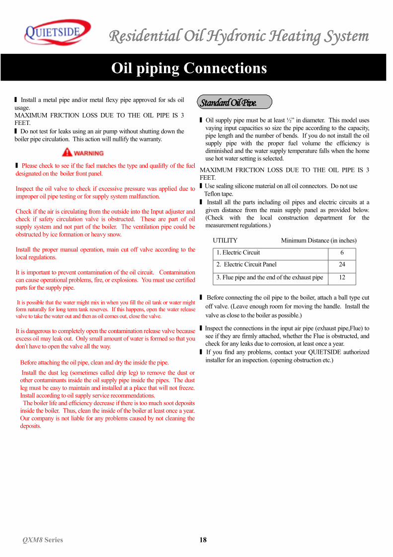
MAXIMUM FRICTION LOSS DUE TO THE OIL PIPE IS 3FEET.■ Use sealing silicone material on all oil connectors. Do not use Teflon tape.■ Install all the parts including oil pipes and electric circuits at a
given distance from the main supply panel as provided below.(Check with the local construction department for themeasurement regulations.)
UTILITY Minimum Distance (in inches)
1. Electric Circuit 6
2. Electric Circuit Panel 24
3. Flue pipe and the end of the exhaust pipe 12
■ Before connecting the oil pipe to the boiler, attach a ball type cutoff valve. (Leave enough room for moving the handle. Install thevalve as close to the boiler as possible.)
■ Inspect the connections in the input air pipe (exhaust pipe,Flue) tosee if they are firmly attached, whether the Flue is obstructed, andcheck for any leaks due to corrosion, at least once a year.
■ If you find any problems, contact your QUIETSIDE authorizedinstaller for an inspection. (opening obstruction etc.)
Standard Oil PipeStandard Oil PipeStandard Oil PipeStandard Oil Pipe....
Residential Residential Residential Residential OilOilOilOil Hydronic Heating System Hydronic Heating System Hydronic Heating System Hydronic Heating System
19 QXM8 Series
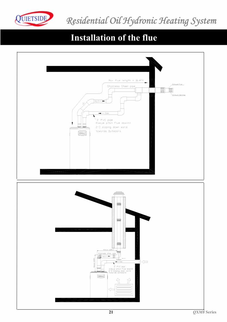
Installation of the flue
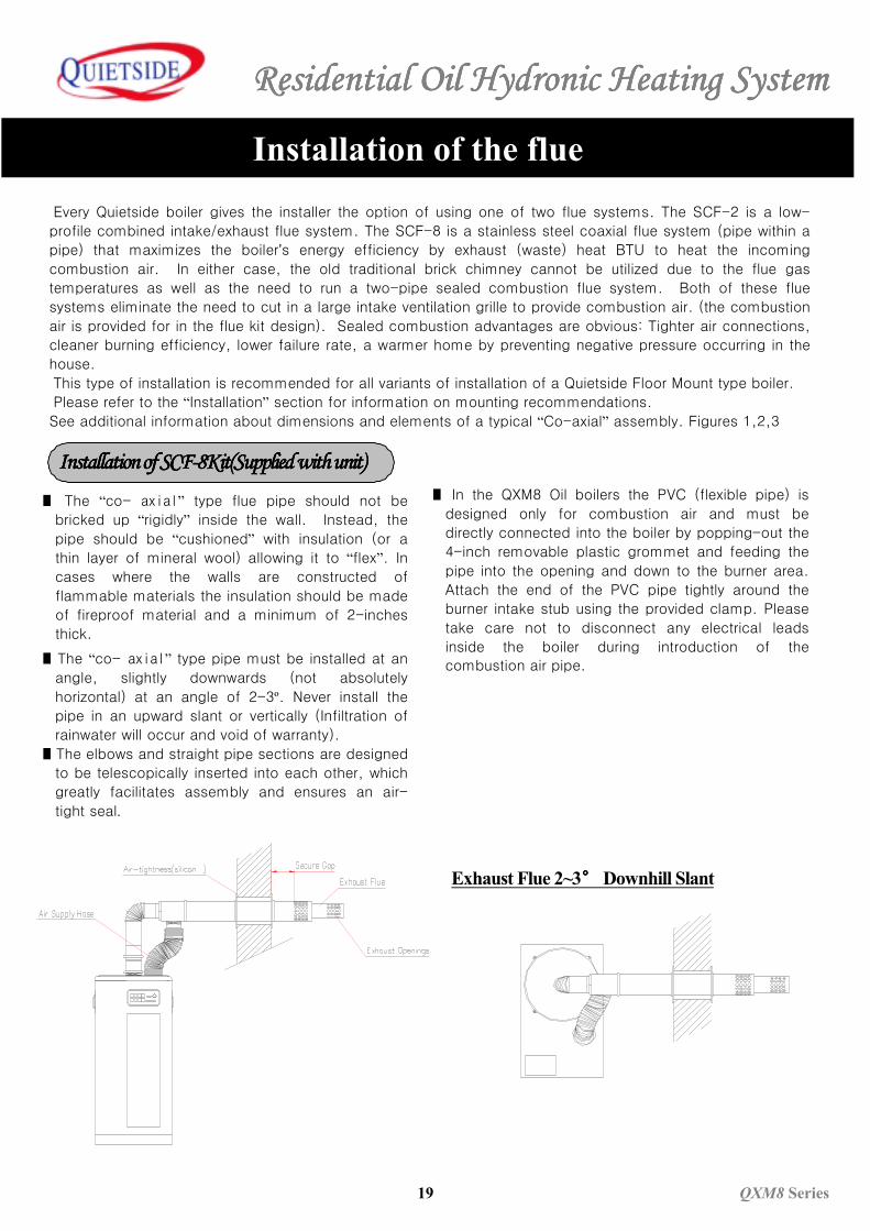
Exhaust Flue 2~3°°°° Downhill Slant
Every Quietside boiler gives the installer the option of using one of two flue systems. The SCF-2 is a low-
profile combined intake/exhaust flue system. The SCF-8 is a stainless steel coaxial flue system (pipe within a
pipe) that maximizes the boiler’s energy efficiency by exhaust (waste) heat BTU to heat the incoming
combustion air. In either case, the old traditional brick chimney cannot be utilized due to the flue gas
temperatures as well as the need to run a two-pipe sealed combustion flue system. Both of these flue
systems eliminate the need to cut in a large intake ventilation grille to provide combustion air. (the combustion
air is provided for in the flue kit design). Sealed combustion advantages are obvious: Tighter air connections,
cleaner burning efficiency, lower failure rate, a warmer home by preventing negative pressure occurring in the
house.
This type of installation is recommended for all variants of installation of a Quietside Floor Mount type boiler.
Please refer to the “Installation” section for information on mounting recommendations.
See additional information about dimensions and elements of a typical “Co-axial” assembly. Figures 1,2,3
■ The “co- axial” type flue pipe should not be
bricked up “rigidly” inside the wall. Instead, the
pipe should be “cushioned” with insulation (or a
thin layer of mineral wool) allowing it to “flex”. In
cases where the walls are constructed of
flammable materials the insulation should be made
of fireproof material and a minimum of 2-inches
thick.
■ The “co- axial” type pipe must be installed at an
angle, slightly downwards (not absolutely
horizontal) at an angle of 2-3º. Never install the
pipe in an upward slant or vertically (Infiltration of
rainwater will occur and void of warranty).
■ The elbows and straight pipe sections are designed
to be telescopically inserted into each other, which
greatly facilitates assembly and ensures an air-
tight seal.
Installation of SCF- Installation of SCF- Installation of SCF- Installation of SCF-8Kit(8Kit(8Kit(8Kit(SuppliedSuppliedSuppliedSupplied with unit) with unit) with unit) with unit)■ In the QXM8 Oil boilers the PVC (flexible pipe) is
designed only for combustion air and must be
directly connected into the boiler by popping-out the
4-inch removable plastic grommet and feeding the
pipe into the opening and down to the burner area.
Attach the end of the PVC pipe tightly around the
burner intake stub using the provided clamp. Please
take care not to disconnect any electrical leads
inside the boiler during introduction of the
combustion air pipe.
Residential Oil Hydronic Heating SystemResidential Oil Hydronic Heating SystemResidential Oil Hydronic Heating SystemResidential Oil Hydronic Heating System
QXM8 Series 20
Installation of the flue
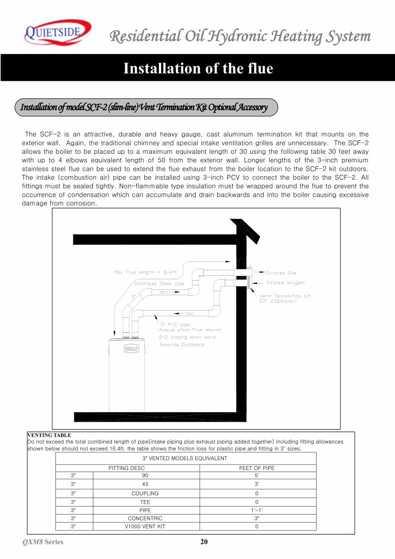
The SCF-2 is an attractive, durable and heavy gauge, cast aluminum termination kit that mounts on the
exterior wall. Again, the traditional chimney and special intake ventilation grilles are unnecessary. The SCF-2
allows the boiler to be placed up to a maximum equivalent length of 30 using the following table 30 feet away
with up to 4 elbows equivalent length of 50 from the exterior wall. Longer lengths of the 3-inch premium
stainless steel flue can be used to extend the flue exhaust from the boiler location to the SCF-2 kit outdoors.
The intake (combustion air) pipe can be installed using 3-inch PCV to connect the boiler to the SCF-2. All
fittings must be sealed tightly. Non-flammable type insulation must be wrapped around the flue to prevent the
occurrence of condensation which can accumulate and drain backwards and into the boiler causing excessive
damage from corrosion.
Installation of model Installation of model Installation of model Installation of model SCF-2 SCF-2 SCF-2 SCF-2 (slim-line) (slim-line) (slim-line) (slim-line) Vent Termination Kit Vent Termination Kit Vent Termination Kit Vent Termination Kit OptionalOptionalOptionalOptional Accessory Accessory Accessory Accessory
VENTING TABLEDo not exceed the total combined length of pipe(intake piping plus exhaust piping added together) including fitting allowances
shown below should not exceed 16.4ft. the table shows the friction loss for plastic pipe and fitting in 3" sizes.
3” VENTED MODELS EQUIVALENT
PITTING DESC FEET OF PIPE
3” 90 5’3” 45 3’
3” COUPLING 0
3” TEE 0
3” PIPE 1’-1’3” CONCENTRIC 3”3” V1000 VENT KIT 0
Residential Residential Residential Residential OilOilOilOil Hydronic Heating System Hydronic Heating System Hydronic Heating System Hydronic Heating System
21 QXM8 Series
Installation of the flue
Residential Oil Hydronic Heating SystemResidential Oil Hydronic Heating SystemResidential Oil Hydronic Heating SystemResidential Oil Hydronic Heating System
QXM8 Series 22
Hydronic Installation
■ An Experienced heating/airconditioning technician, correctly certified must install the boiler. ■ Boiler must be started by a certified technician or factory experienced technician and any failure to follow the safety procedures
in instsallation may cause extremely negative effects on the expected life of the boiler, and the safe and proper operation of thesystem. Pay attention to the recommended items in the installation instructions and verify how to operate the system at theoptimal level. .
■ For pump installation follow the instructions provided for recommended installation. There are many examples of installationmethods, however if you do not consult with a QUIETSIDE Corporation Representative before installation then it is highlyimportant that you follow the installation instruction for 100% proper operation guarantee.
■ Boiler parts (valves, filter, etc) must be easily accessible and all connections must be detachable (use unions etc).■ When installing the central heating section, include the drain (flush) valve and/or automatic drainage.. All drain pipes must be
facing the floor.■ During the installation, be careful not to allow other materials such as lubricating oil, dust, sand, metal shavings, and excessive
silicone cement in the heating and hot water pipe. After finishing the boiler installation flush the the central heating system .(This ensures longer life-term of the boiler equipement and reduces malfunctions.) When it’s a new system, conduct a watercirculation test and at this time, use extreme caution to not exceed maximum operation pressure for each device. Caution: Themaximum boiler pressure for QXM8,QXW8 is 49.8 psig.
■ The system does not require a safety pressure relief valve on the water heater since this system produces hot water as requiredby continuously circulating water. (For Dual Function Boilers)
■ In special cases, these additional devices are necessary. (it is not dangerous but it can be inconvenient without these devices.):- In an installation including a thermostat heater valve, additionally install a relief release valve. (The release valve or Pressure
sustaining differential valve) While installing this relief release valve, it creates a continuous, adjustable, and usable differentialpressure between the boiler input and return parts. This guarantees proper operation of the thermostat. (Effective valve oper-ation , controller accuracy, circulation noise reduction.)
- A Pressure reducing valve must be installed when the water pressure in the house exceeds the maximum pressure, 87 psig. (thiscauses faucet noise if the pressure is over the standard 44 psig.) This is recommended for the entire system although the boilerdoes not require the pressure reducer even with faucet water pressure is over 160psig.
An A.S.M.E. grade pressure relief valve or top air pressure setting of 55 psi T&P MUST BE INSTALLED. Do notinstall any shut off valve or plug the line between the valve and the boiler or the valve and the drain. If you do notadhere to these recommendations, Quietside are not responsible for any serious damage or injuries that may occur..
Residential Residential Residential Residential OilOilOilOil Hydronic Heating System Hydronic Heating System Hydronic Heating System Hydronic Heating System
23 QXM8 Series
Hydronic Installation
Check List1 . Check the oil type. (Indicated on the boiler nameplate – located on the top panel of the boiler.2. Check to see if the Boiler drain valve is open.3. Check if the ground is connected.4. Check to make sure the power supply is a 15 Amp 120 V AC circuit. 5. Check for proper installation, whether all water circulator pipes are standard size and meet the local construction
regulations. 6. Vent out all air from the pipes at that time.7. Check if proper venting pipe, slope, and arrangement for the QXM8,QXW8 boiler has been installed.8. Install Roomcon-7 indoor automatic temperature control.9. Check the electric connections in the unit and check for leaks in the waterside connections.
1. Shut off the faucet after filling all the pipes connecting to the boiler.2. Use automatic system to fill the boiler with water (provided by installator) and wait until the circulation pipe system water
pressure reaches the maximum pressure. (The maximum pressure to fill the water through the valve is 30 psi forQXM8,QXW8 boiler. )
3. Wait until water is full.4. Connect the boiler to 120 V power source. Set the thermostat in the boiler to “on.”5. Use the following troubleshooting measures if indicator lights up as having a problem. After all the corrections and
adjustments are made, restart the boiler. Reconnecting the boiler by turning off the power switch to restart the boiler may benecessary.
6. First turn off the boiler if there is a water leak. Shut off all valves. Inspect and test all connectors and exchange as needed,tighten, or repair them. Before opening the valve, check to see if all the structure and parts are in its correct place.Attention: If there is air in the hot water pipes, then corrosion occurs in the boiler, whole circulation heating system muchfaster. Be careful and take sufficient time before going to the next step and completely remove all the air from the pipes.
Preparation for Test OperationPreparation for Test OperationPreparation for Test OperationPreparation for Test Operation
Trial OperationTrial OperationTrial OperationTrial Operation
Residential Oil Hydronic Heating SystemResidential Oil Hydronic Heating SystemResidential Oil Hydronic Heating SystemResidential Oil Hydronic Heating System
QXM8 Series 24
Hydronic Installation
1. Fill the water using automatic pressure reducer valve or maual refill valve. (Installation dealer will offer one or more types ofthe valves.)2. Eliminate all waste material by cleaning out the existing pipe system. (oil, dirt, metal filings, pipe dope, etc)3. Start operating the pump.4. Release the air from the piping system.5. Do not use chemical detergent or additive that stops leaks in the system. Such acts will damage the system and are notcovered under the warranty.
To prevent SCALDS AND BURNS INSTALL A MIXING VALVE IN THE DOMESTIC HOT WATER SYSTEM.
Mixing Valve has these functions and features:■ It maintains water temperature at the faucet.(accuracy within2ºF ) (User selects the water temperature.)■ It insures safe water temperature through inserting burn Guard device.■ Eliminate scale and build up inside the boiler before installation.■ Wire mesh insertion device and check valve increases the life-span of the system and solves problems.
Factory Setting 109℉
Temperature Control Range 95-131℉
Maximum Water Temperature 176℉
Input water temperature range 41-77℉
Temperature Stablization ± 2℉
Maximum Oil Density 1.06 gpm Max static pressure 145 psig
Mixing valve is temperature sensitive. During the installation, take care not to expose the valve to extreme temperatures. Todo this, install the valve as the last part of the installation. (Conduct oil leakage test and clean before installation)
Set temperature and ensure that the valve setting cannot be tampered with.
Thermostatic Mixing Valve Thermostatic Mixing Valve Thermostatic Mixing Valve Thermostatic Mixing Valve (Anti-Scald T & P Valve)(Anti-Scald T & P Valve)(Anti-Scald T & P Valve)(Anti-Scald T & P Valve)
Filling the SystemFilling the SystemFilling the SystemFilling the System
InstallationInstallationInstallationInstallation
Residential Residential Residential Residential OilOilOilOil Hydronic Heating System Hydronic Heating System Hydronic Heating System Hydronic Heating System
25 QXM8 Series
Hydronic Installation
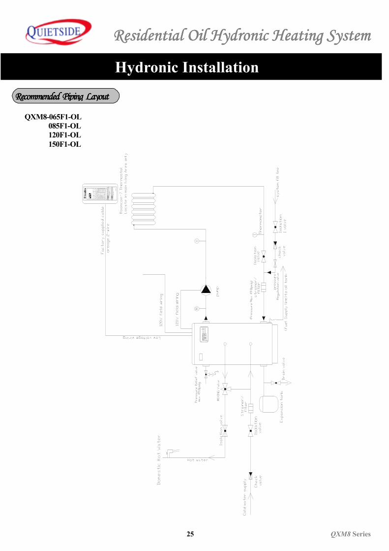
Recommended Piping LayoutRecommended Piping LayoutRecommended Piping LayoutRecommended Piping Layout
QXM8-065F1-OL 085F1-OL 120F1-OL 150F1-OL
41°
4
95° F
F
INST
ION
CONT
INUO
US
POW
EROP
ERAT
ION
CONT
RIL
THER
MAL
HOT
WAT
ER
GOIN
G O
UTTI
MER
REPE
AT
ROOM
CON
7
REPE
AT T
IMER
TEM
P CO
NTR
OL2.
50H
r
Residential Oil Hydronic Heating SystemResidential Oil Hydronic Heating SystemResidential Oil Hydronic Heating SystemResidential Oil Hydronic Heating System
QXM8 Series 26
Hydronic Installation
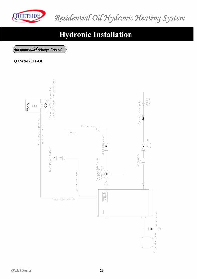
QXW8-120F1-OL
Recommended Piping LayoutRecommended Piping LayoutRecommended Piping LayoutRecommended Piping LayoutRO
OMCO
N-1
5
Residential Residential Residential Residential OilOilOilOil Hydronic Heating System Hydronic Heating System Hydronic Heating System Hydronic Heating System
27 QXM8 Series
Hydronic Installation
■ Keep these items to prevent temperature control malfunctioning at the mixing valve.■ Loosen the bolt that holds the red control handle with a key on the valve. (Included by the manufacturer)Separate the control handle from the locked safety device and place it on the valve to completely remove the control handle.■ Open the hot water and cold water compartment entrances completely and set the temperature to the most useful watertemperature. (Turn counterclockwise for hot water and clockwise for lower temperature). When you set the temperature; set thewater flow in the valve to minimum 1.06 gpm; and hot water that is going out of the valve should maintain the temperature forabout 2-3 minutes.■ Release the controller handle and reattach the handle to the lock safety device.■ Tighten the controller handle with the key provided by the manufacturer.
Although properly installed thermostat device does not have to be serviced separately, it needs to be inspected every sixmonths. (Clean the wire filter when neccessary)
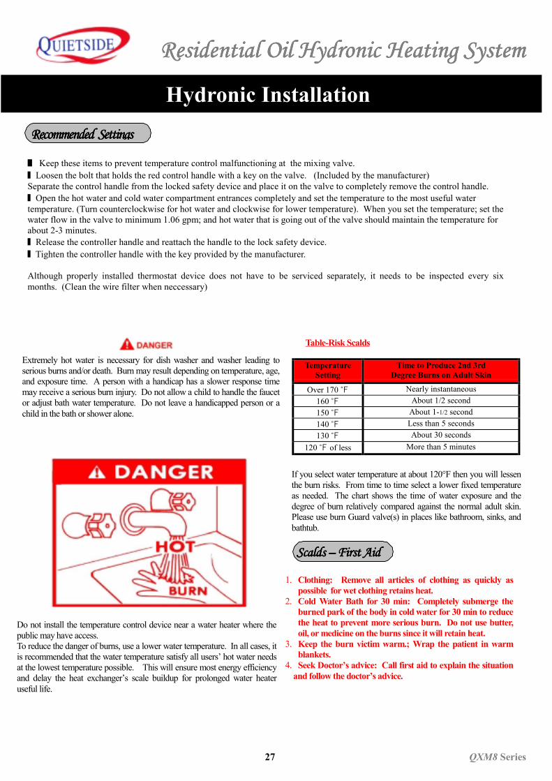
Extremely hot water is necessary for dish washer and washer leading toserious burns and/or death. Burn may result depending on temperature, age,and exposure time. A person with a handicap has a slower response timemay receive a serious burn injury. Do not allow a child to handle the faucetor adjust bath water temperature. Do not leave a handicapped person or achild in the bath or shower alone.
Do not install the temperature control device near a water heater where thepublic may have access.To reduce the danger of burns, use a lower water temperature. In all cases, itis recommended that the water temperature satisfy all users’ hot water needsat the lowest temperature possible. This will ensure most energy efficiencyand delay the heat exchanger’s scale buildup for prolonged water heateruseful life.
Table-Risk Scalds
1. Clothing: Remove all articles of clothing as quickly aspossible for wet clothing retains heat.
2. Cold Water Bath for 30 min: Completely submerge theburned park of the body in cold water for 30 min to reducethe heat to prevent more serious burn. Do not use butter,oil, or medicine on the burns since it will retain heat.
3. Keep the burn victim warm.; Wrap the patient in warmblankets.
4. Seek Doctor’s advice: Call first aid to explain the situationand follow the doctor’s advice.
If you select water temperature at about 120°F then you will lessenthe burn risks. From time to time select a lower fixed temperatureas needed. The chart shows the time of water exposure and thedegree of burn relatively compared against the normal adult skin.Please use burn Guard valve(s) in places like bathroom, sinks, andbathtub.
Scalds Scalds Scalds Scalds –––– First Aid First Aid First Aid First Aid
Recommended Recommended Recommended Recommended Setting Setting Setting Settingssss
TemperatureSetting
Time to Produce 2nd 3rdDegree Burns on Adult Skin
Over 170 ℉ Nearly instantaneous160 ℉ About 1/2 second150 ℉ About 1-1/2 second140 ℉ Less than 5 seconds130 ℉ About 30 seconds
120 ℉ of less More than 5 minutes
Residential Oil Hydronic Heating SystemResidential Oil Hydronic Heating SystemResidential Oil Hydronic Heating SystemResidential Oil Hydronic Heating System
QXM8 Series 28
Using The Thermostat
■ Do not install near heat source or these places: (lights, TV, fireplace, space heater, sunlight,etc.)
■ Do not install where there may be exposure to external elements.(Staircase, porch, exits, or near the outside wall.)
■ Do not install in an area blocked off from the rest of the house.
■ In a multi-level house, install on the first floor
■ Install about four to five feet above the floor.■ Install the system in a place where it is out of reach for children.
.
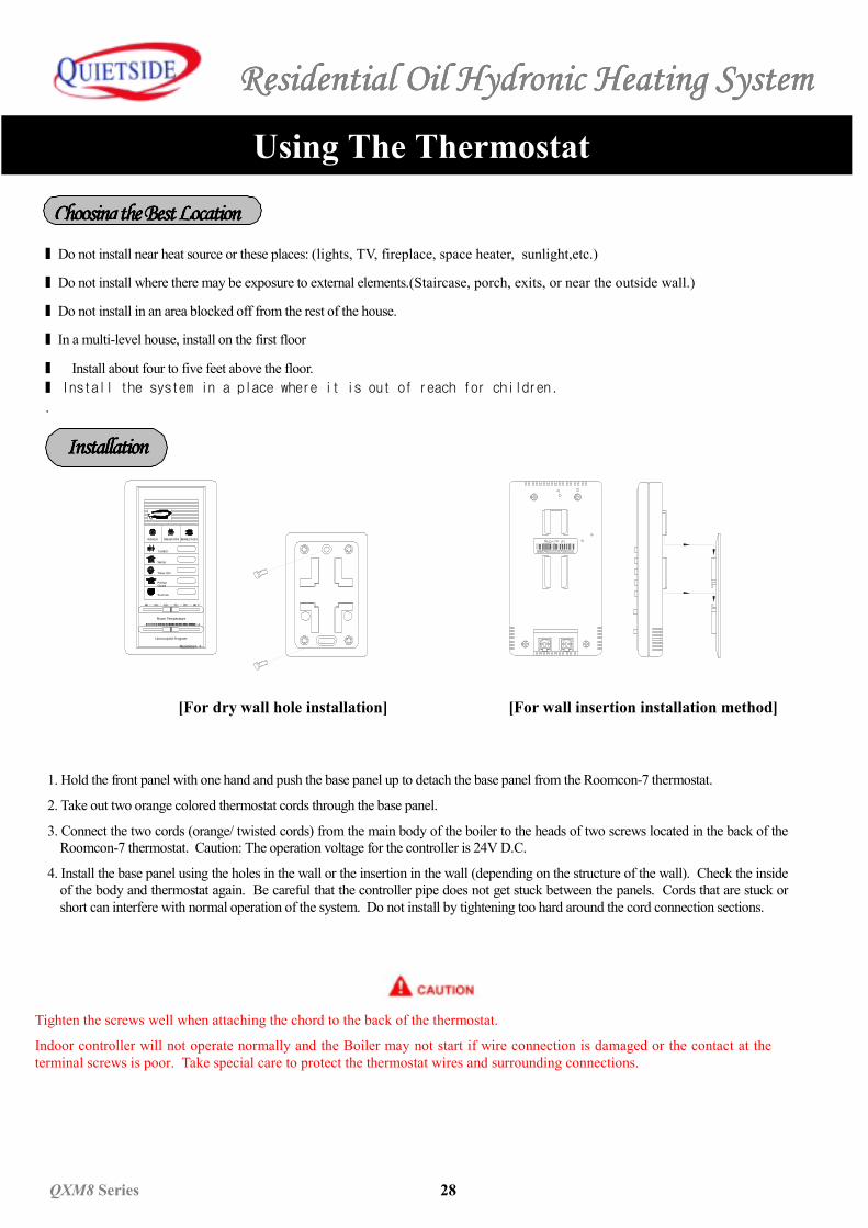
[For dry wall hole installation]
Tighten the screws well when attaching the chord to the back of the thermostat.
Indoor controller will not operate normally and the Boiler may not start if wire connection is damaged or the contact at theterminal screws is poor. Take special care to protect the thermostat wires and surrounding connections.
1. Hold the front panel with one hand and push the base panel up to detach the base panel from the Roomcon-7 thermostat.
2. Take out two orange colored thermostat cords through the base panel.
3. Connect the two cords (orange/ twisted cords) from the main body of the boiler to the heads of two screws located in the back of theRoomcon-7 thermostat. Caution: The operation voltage for the controller is 24V D.C.
4. Install the base panel using the holes in the wall or the insertion in the wall (depending on the structure of the wall). Check the insideof the body and thermostat again. Be careful that the controller pipe does not get stuck between the panels. Cords that are stuck orshort can interfere with normal operation of the system. Do not install by tightening too hard around the cord connection sections.
TURBO
Summer
Room Temperature
Unoccupied Program
4 Hr02.5
RoomCon 7
40 °F9060 70
QUIETSIDE
Winter
FreezeGuard
50 80
Timer ON
검 사 필UNIK
MADE IN KOREA
인
검
InstallationInstallationInstallationInstallation
Choosing the Best LocationChoosing the Best LocationChoosing the Best LocationChoosing the Best Location
[For wall insertion installation method]
Residential Oil Hydronic Heating System
29292929 QXM8QXM8QXM8QXM8 Series Series Series Series
``
Using the ThermostatUsing the ThermostatUsing the ThermostatUsing the Thermostat
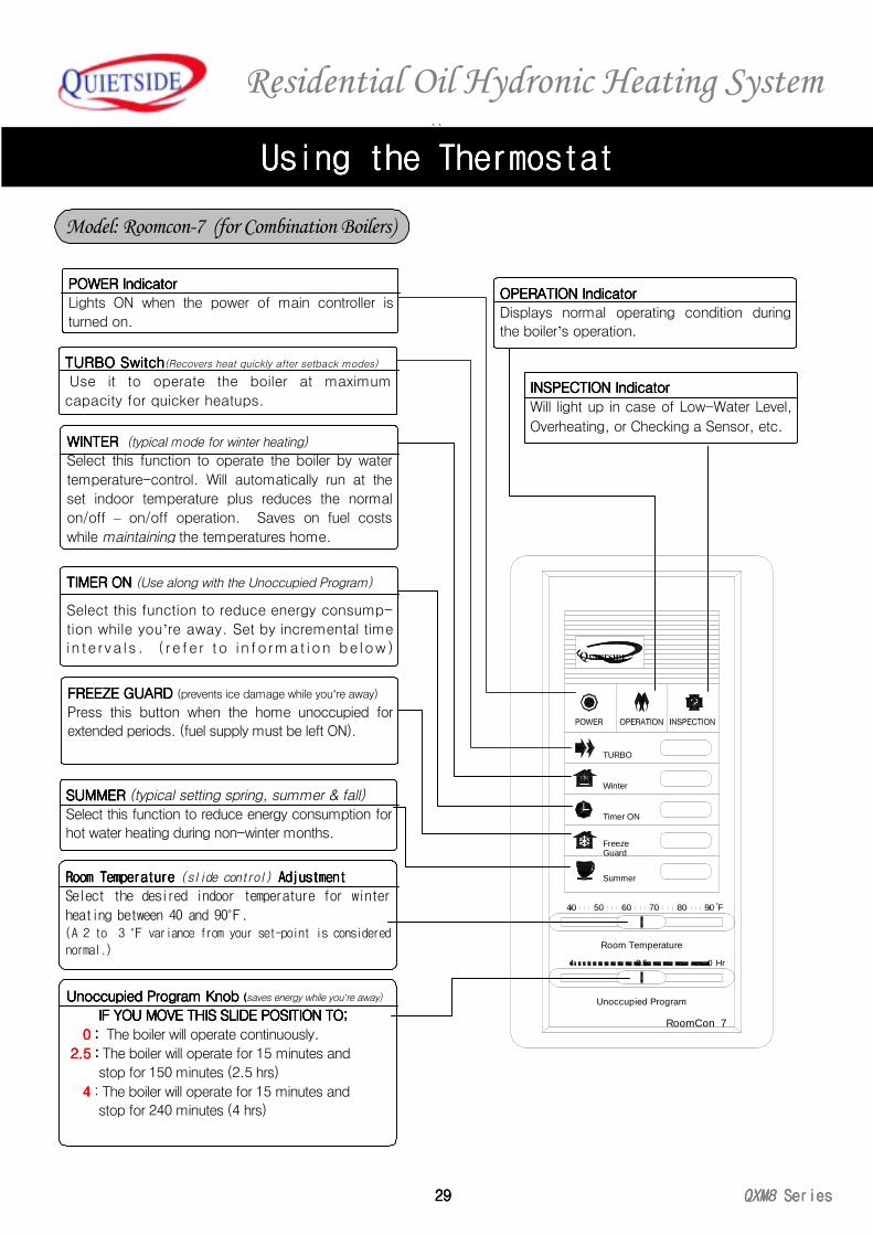
INSPECTION IndicatorINSPECTION IndicatorINSPECTION IndicatorINSPECTION Indicator
Will light up in case of Low-Water Level,
Overheating, or Checking a Sensor, etc.
TURBO TURBO TURBO TURBO SwitchSwitchSwitchSwitch(Recovers heat quickly after setback modes)
Use it to operate the boiler at maximum
capacity for quicker heatups.
POWER IndicatorPOWER IndicatorPOWER IndicatorPOWER Indicator
Lights ON when the power of main controller is
turned on.
WINTER WINTER WINTER WINTER (typical mode for winter heating)
Select this function to operate the boiler by water
temperature-control. Will automatically run at the
set indoor temperature plus reduces the normal
on/off – on/off operation. Saves on fuel costs
while maintaining the temperatures home.
TIMER ONTIMER ONTIMER ONTIMER ON (Use along with the Unoccupied Program)
Select this function to reduce energy consump-
tion while you’re away. Set by incremental time
in terva ls . ( r e fer to in format ion be low)
OPERATION IndicatorOPERATION IndicatorOPERATION IndicatorOPERATION Indicator
Displays normal operating condition during
the boiler’s operation.
FREEZE GUARDFREEZE GUARDFREEZE GUARDFREEZE GUARD (prevents ice damage while you’re away)
Press this button when the home unoccupied for
extended periods. (fuel supply must be left ON).
SUMMER SUMMER SUMMER SUMMER (typical setting spring, summer & fall)
Select this function to reduce energy consumption for
hot water heating during non-winter months.
Room Room Room Room Temperature Temperature Temperature Temperature (slide control) Adjustment Adjustment Adjustment Adjustment
Select the desired indoor temperature for winter
heating between 40 and 90℉.(A 2 to 3 ℉ variance from your set-point is considered
normal.)
Unoccupied Program KnobUnoccupied Program KnobUnoccupied Program KnobUnoccupied Program Knob ((((saves energy while you’re away)
IF YOU MOVE THISIF YOU MOVE THISIF YOU MOVE THISIF YOU MOVE THIS SLIDE POSITION TO SLIDE POSITION TO SLIDE POSITION TO SLIDE POSITION TO;;;;
0 0 0 0 :::: The boiler will operate continuously.
2.5 2.5 2.5 2.5 :::: The boiler will operate for 15 minutes and
stop for 150 minutes (2.5 hrs)
4444 : The boiler will operate for 15 minutes and
stop for 240 minutes (4 hrs)
TURBO
Summer
Room Temperature
Unoccupied Program
4 Hr02.5
RoomCon 7
40 °F9060 70
QUIETSIDE
Winter
FreezeGuard
50 80
Timer ON
Model: Roomcon-7 (for Combination Boilers)
Residential Oil Hydronic Heating System
QXM8QXM8QXM8QXM8 SeriesSeriesSeriesSeries 30303030
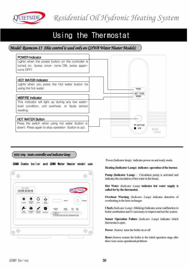
QXM8 QXM8 QXM8 QXM8 Combo boiler andCombo boiler andCombo boiler andCombo boiler and QXW8 QXW8 QXW8 QXW8 Water HeaterWater HeaterWater HeaterWater Heater model usemodel usemodel usemodel use Power (Indicator lamp): indicates power on and ready mode.
Heating (Indicator Lamp): indicates operation of the burner.
Pump (Indicator Lamp) : Circulation pump is activated andindicates the circulation of hot water in the house.
Hot Water (Indicator Lamp) indicates hot water supply iscalled for by the thermostat.
Overheat Warning (Indicator Lamp) indicates detection ofoverheating in the heat exchanger.
Check (Indicator Lamp) (blinking) Indicates some malfunction inboiler combustion and it’s necessary to inspect and test the system.
Sensor Operation Failure (Indicator Lamp) indicates whichthermostat is open.
Power (button) turns the boiler on or off
Reset (button) restarts the boiler to the initial operation stage afterthere were some operational problems
Using the ThermostatUsing the ThermostatUsing the ThermostatUsing the Thermostat
Model: Roomcon-15 (this control is used only on QXW8 Water Heater Models)Model: Roomcon-15 (this control is used only on QXW8 Water Heater Models)Model: Roomcon-15 (this control is used only on QXW8 Water Heater Models)Model: Roomcon-15 (this control is used only on QXW8 Water Heater Models)
KDC-104p M KDC-104p M KDC-104p M KDC-104p Main controller and indicator lampain controller and indicator lampain controller and indicator lampain controller and indicator lamp
UIETSIDEQ
HOT WATER IndicatorHOT WATER IndicatorHOT WATER IndicatorHOT WATER Indicator
Lights when you press the Hot water button forusing the hot water.
POWER IndicatorPOWER IndicatorPOWER IndicatorPOWER Indicator
Lights when the power button on the controller is
turned on. (press once- turns ON, press again-
turns OFF)
MISFIRE IndicatorMISFIRE IndicatorMISFIRE IndicatorMISFIRE Indicator
This indicator will light up during any low water-
level condition, unit overheat, or faulty sensor
reading.
HOT WATER HOT WATER HOT WATER HOT WATER ButtonButtonButtonButton
Press the switch when using hot water (button is
down) Press again to stop operation (button is up).
Residential Oil Hydronic Heating SystemResidential Oil Hydronic Heating SystemResidential Oil Hydronic Heating SystemResidential Oil Hydronic Heating System
31313131 QXM8QXM8QXM8QXM8 Series Series Series Series
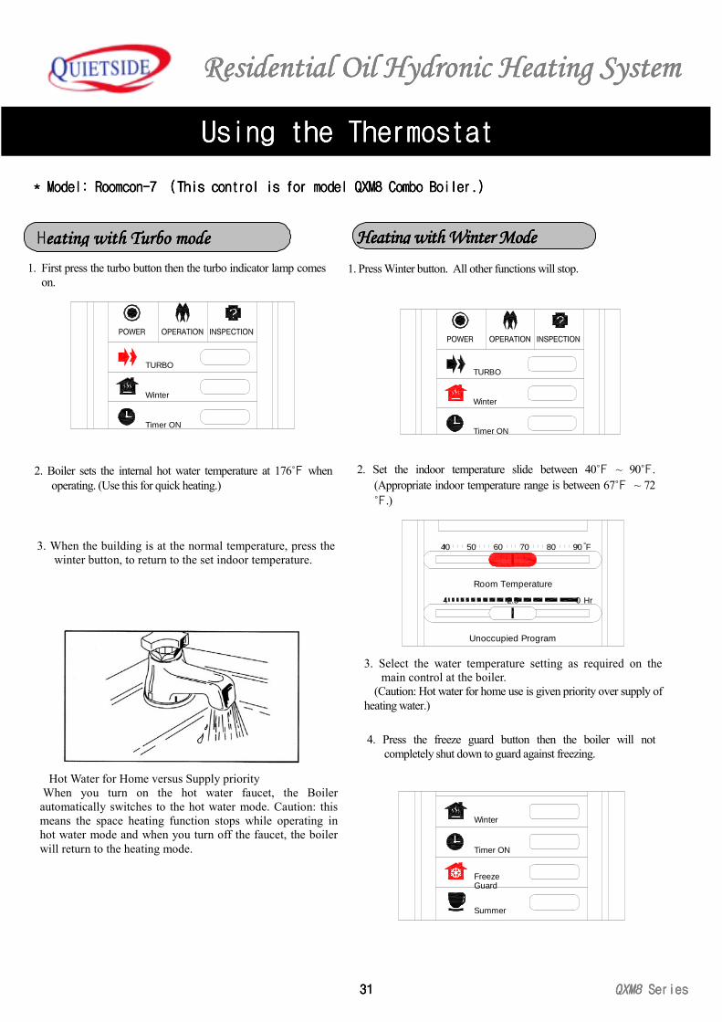
2. Boiler sets the internal hot water temperature at 176℉ whenoperating. (Use this for quick heating.)
3. When the building is at the normal temperature, press thewinter button, to return to the set indoor temperature.
Hot Water for Home versus Supply priority When you turn on the hot water faucet, the Boilerautomatically switches to the hot water mode. Caution: thismeans the space heating function stops while operating inhot water mode and when you turn off the faucet, the boilerwill return to the heating mode.
1. First press the turbo button then the turbo indicator lamp comeson.
TURBO
Timer ON
Winter
Timer ON
Summer
GuardFreeze
Winter
1. Press Winter button. All other functions will stop.
2. Set the indoor temperature slide between 40℉ ~ 90℉.(Appropriate indoor temperature range is between 67℉ ~ 72℉.)
3. Select the water temperature setting as required on themain control at the boiler.
(Caution: Hot water for home use is given priority over supply ofheating water.)
4. Press the freeze guard button then the boiler will notcompletely shut down to guard against freezing.
TURBO
Timer ON
Winter
60
Unoccupied Program
Room Temperature
4
40 50
2.5
70 80
Hr0
F90°
* * * * Model: Roomcon-Model: Roomcon-Model: Roomcon-Model: Roomcon-7777 (This (This (This (This controlcontrolcontrolcontrol is for model is for model is for model is for model QXM8 QXM8 QXM8 QXM8 Combo Boiler.Combo Boiler.Combo Boiler.Combo Boiler.))))
Using the ThermostatUsing the ThermostatUsing the ThermostatUsing the Thermostat
Heating with Turbo modeeating with Turbo modeeating with Turbo modeeating with Turbo mode HHHHeating with Winter Modeeating with Winter Modeeating with Winter Modeeating with Winter Mode
Residential Oil Hydronic Heating SystemResidential Oil Hydronic Heating SystemResidential Oil Hydronic Heating SystemResidential Oil Hydronic Heating System
QXM8QXM8QXM8QXM8 SeriesSeriesSeriesSeries 32323232
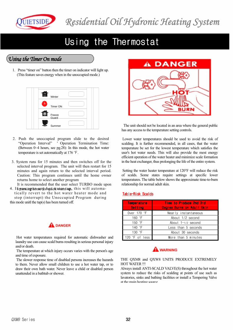
1. Press “timer on” button then the timer on indicator will light up.(This feature saves energy when in the unoccupied mode.)
2. Push the unoccupied program slide to the desired“Operation Interval” ' Operation Termination Time:(Between 0~4 hours, see pg.28): In this mode, the hot watertemperature is set automatically at 176 ℉.
3. System runs for 15 minutes and then switches off for theselected interval program. The unit will then restart for 15minutes and again return to the selected interval period.Caution: This program continues until the home ownerreturns home to select another programIt is recommended that the user select TURBO mode uponreturning home for quick warm up.4. I f you open any hot water tap, this will automa-
t ica l ly r ever t to the ho t wa te r hea ter mo de andstop (interrupt) the Unoccupied Program dur ing
this mode unitl the tap(s) has been turned off.
Timer ON
Summer
GuardFreeze
Winter
Hot water temperatures required for automatic dishwasher andlaundry use can cause scald burns resulting in serious personal injuryand/or death. The temperature at which injury occurs varies with the person's ageand time of exposure. The slower response time of disabled persons increases the hazardsto them. Never allow small children to use a hot water tap, or todraw their own bath water. Never leave a child or disabled personunattended in a bathtub or shower.
The unit should not be located in an area where the general publichas any access to the temperature setting controls.
Lower water temperatures should be used to avoid the risk ofscalding. It is further recommended, in all cases, that the watertemperature be set for the lowest temperature which satisfies theuser's hot water needs. This will also provide the most energyefficient operation of the water heater and minimize scale formationin the heat exchanger, thus prolonging the life of the entire system.
Setting the water heater temperature at 120°F will reduce the riskof scalds. Some states require settings at specific lowertemperatures. The table below shows the approximate time-to-burnrelationship for normal adult skin.
Table-Risk ScaldsTable-Risk ScaldsTable-Risk ScaldsTable-Risk Scalds
THE QXM8 and QXW8 UNITS PRODUCE EXTREMELYHOT WATER !!!Always install ANTI-SCALD VALVE(S) throughout the hot watersystem to reduce the risks of scalding at points of use such aslavatories, sinks and bathing facilities or install a Tempering Valveat the main heating source.
Using the ThermostatUsing the ThermostatUsing the ThermostatUsing the Thermostat
Using the Timer Using the Timer Using the Timer Using the Timer On modeOn modeOn modeOn mode
TemperatureTemperatureTemperatureTemperature
SettingSettingSettingSetting
Time to Produce 2nd 3rdTime to Produce 2nd 3rdTime to Produce 2nd 3rdTime to Produce 2nd 3rd
Degree Burns on Adult SkinDegree Burns on Adult SkinDegree Burns on Adult SkinDegree Burns on Adult Skin
Over 170 ℉ Nearly instantaneous
160 ℉ About 1/2 second
150 ℉ About 1-1/2 second
140 ℉ Less than 5 seconds
130 ℉ About 30 seconds
120 ℉ of less More than 5 minutes
Residential Oil Hydronic Heating SystemResidential Oil Hydronic Heating SystemResidential Oil Hydronic Heating SystemResidential Oil Hydronic Heating System
33333333 QXM8QXM8QXM8QXM8 Series Series Series Series
Using the ThermostatUsing the ThermostatUsing the ThermostatUsing the Thermostat
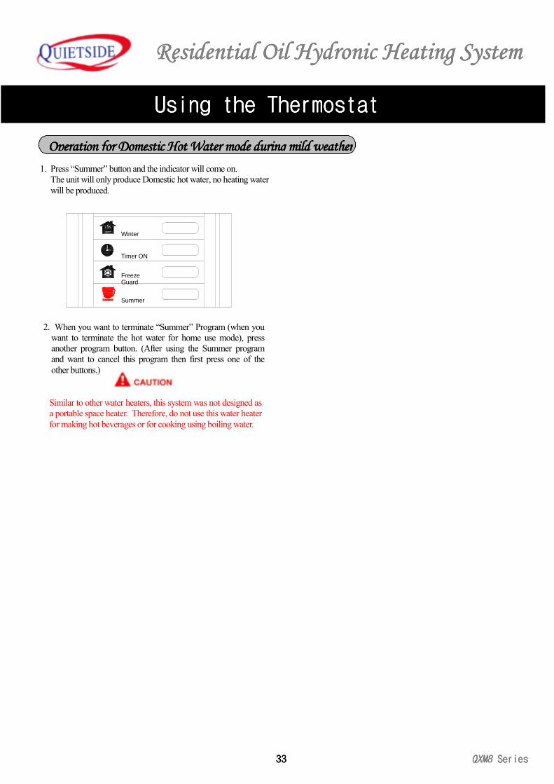
1. Press “Summer” button and the indicator will come on.The unit will only produce Domestic hot water, no heating waterwill be produced.
2. When you want to terminate “Summer” Program (when youwant to terminate the hot water for home use mode), pressanother program button. (After using the Summer programand want to cancel this program then first press one of theother buttons.)
Similar to other water heaters, this system was not designed asa portable space heater. Therefore, do not use this water heaterfor making hot beverages or for cooking using boiling water.
Timer ON
Summer
GuardFreeze
Winter
Operation for Domestic Hot Water mode during mild weatherOperation for Domestic Hot Water mode during mild weatherOperation for Domestic Hot Water mode during mild weatherOperation for Domestic Hot Water mode during mild weather
Residential Oil Hydronic Heating SystemResidential Oil Hydronic Heating SystemResidential Oil Hydronic Heating SystemResidential Oil Hydronic Heating System
QXM8QXM8QXM8QXM8 SeriesSeriesSeriesSeries 34343434
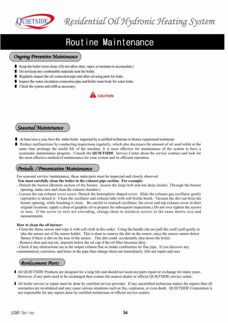
■ All QUIETSIDE Products are designed for a long life and should not need any parts repair or exchange for many years.However, if any parts need to be exchanged then contact the nearest dealer or official QUIETSIDE service center.
■ All boiler service or repair must be done by certified service provider. If any uncertified technician makes the repairs then allwarranties are invalidated and may cause serious situations such as fire, explosion, or even death. QUIETSIDE Corporation isnot responsible for any repairs done by certified technicians or official service centers.
■ Keep the boiler room clean. (Do not allow dust, vapor, or moisture to accumulate.)■ Do not keep any combustible materials near the boiler.■ Regularly inspect the oil connection pipe and other oil using parts for leaks.■ Inspect the water circulation connection pipe and boiler main body for water leaks.■ Check the system and refill as necessary.
■ At least once a year, have the entire boiler inspected by a certified technician or factory experienced technician.■ Reduce malfunctions by conducting inspections regularly, which also decreases the amount of oil used while at the
same time prolongs the useful life of the machine. It is most effective for maintenance of the system to have asystematic maintenance program. Consult the QUIETSIDE Service Center about the service contract and look forthe most effective method of maintenance for your system and its efficient operation.
For seasonal service/ maintenance, these main parts must be inspected and closely observed: You must carefully clean the boiler in the exhaust pipe section. For example:- Detach the burner.(Bottom section of the burner, loosen the large bolt and nut deep inside). Through the burner
opening, make sure and clean the exhaust chamber.)- Loosen the top exhaust cover screw. Detach the hemisphere shaped cover. Slide the exhaust gas oscillator gently
(upwards) to detach it. Clean the oscillator and exhaust tube with soft bristle brush. Vacuum the dirt out from theburner opening, while brushing it clean. Be careful to reattach oscillator, the cover and top exhaust cover in theiroriginal locations. (apply a drop of graphite oil to prepare for subsequent inspections.) Do not over tighten the screwsor nuts. If the screw or nuts are corroding, change them to stainless screws in the same metric size andmeasurements.
How to clean the oil burner:- Clean the flame sensor and wipe it with soft cloth in this order: Using the handle (do not pull the cord!) pull gently to
take the sensor out of the sensor holder. This is done to remove the dirt on the sensor, since the sensor cannot detectflames if there is dirt on the lens of the sensor . This dirt could accidentally shut down the boiler.
- Remove dust and rust etc. deposits below the oil cup if the oil filter becomes dirty.- Check if any obstructions are at the output exhaust flue or intake combustion air flue pipe. If you discover anycontamination, corrosion, and holes in the pipe then change them out immediately. (Do not repair and use)
Routine MaintenanceRoutine MaintenanceRoutine MaintenanceRoutine Maintenance
Ongoing Preventive MaintenanceOngoing Preventive MaintenanceOngoing Preventive MaintenanceOngoing Preventive Maintenance
Seasonal MaintenanceSeasonal MaintenanceSeasonal MaintenanceSeasonal Maintenance
Periodic / Preventative MaintenancePeriodic / Preventative MaintenancePeriodic / Preventative MaintenancePeriodic / Preventative Maintenance
Replacement PartsReplacement PartsReplacement PartsReplacement Parts
Residential Residential Residential Residential Oil Oil Oil Oil Hydronic Heating SystemHydronic Heating SystemHydronic Heating SystemHydronic Heating System
35353535 QXM8QXM8QXM8QXM8 Series Series Series Series
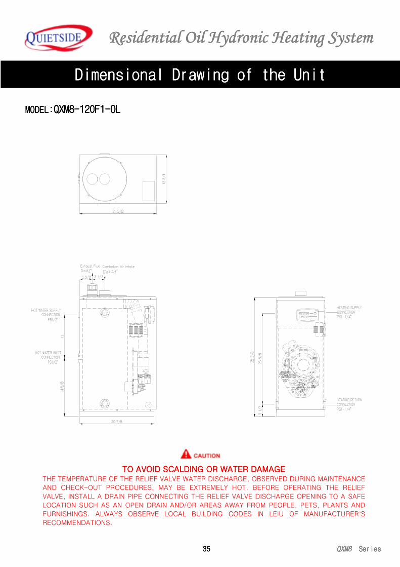
MODELMODELMODELMODEL::::QXM8-120F1-OLQXM8-120F1-OLQXM8-120F1-OLQXM8-120F1-OL
Dimensional Drawing of the UnitDimensional Drawing of the UnitDimensional Drawing of the UnitDimensional Drawing of the Unit
TO AVOID SCALDING OR WATER DAMAGETO AVOID SCALDING OR WATER DAMAGETO AVOID SCALDING OR WATER DAMAGETO AVOID SCALDING OR WATER DAMAGETHE TEMPERATURE OF THE RELIEF VALVE WATER DISCHARGE, OBSERVED DURING MAINTENANCE
AND CHECK-OUT PROCEDURES, MAY BE EXTREMELY HOT. BEFORE OPERATING THE RELIEF
VALVE, INSTALL A DRAIN PIPE CONNECTING THE RELIEF VALVE DISCHARGE OPENING TO A SAFE
LOCATION SUCH AS AN OPEN DRAIN AND/OR AREAS AWAY FROM PEOPLE, PETS, PLANTS AND
FURNISHINGS. ALWAYS OBSERVE LOCAL BUILDING CODES IN LEIU OF MANUFACTURER’SRECOMMENDATIONS.
Residential Residential Residential Residential Oil Oil Oil Oil Hydronic Heating SystemHydronic Heating SystemHydronic Heating SystemHydronic Heating System
QXM8 QXM8 QXM8 QXM8 Series Series Series Series 36363636
Dimensional Drawing of the UnitDimensional Drawing of the UnitDimensional Drawing of the UnitDimensional Drawing of the Unit
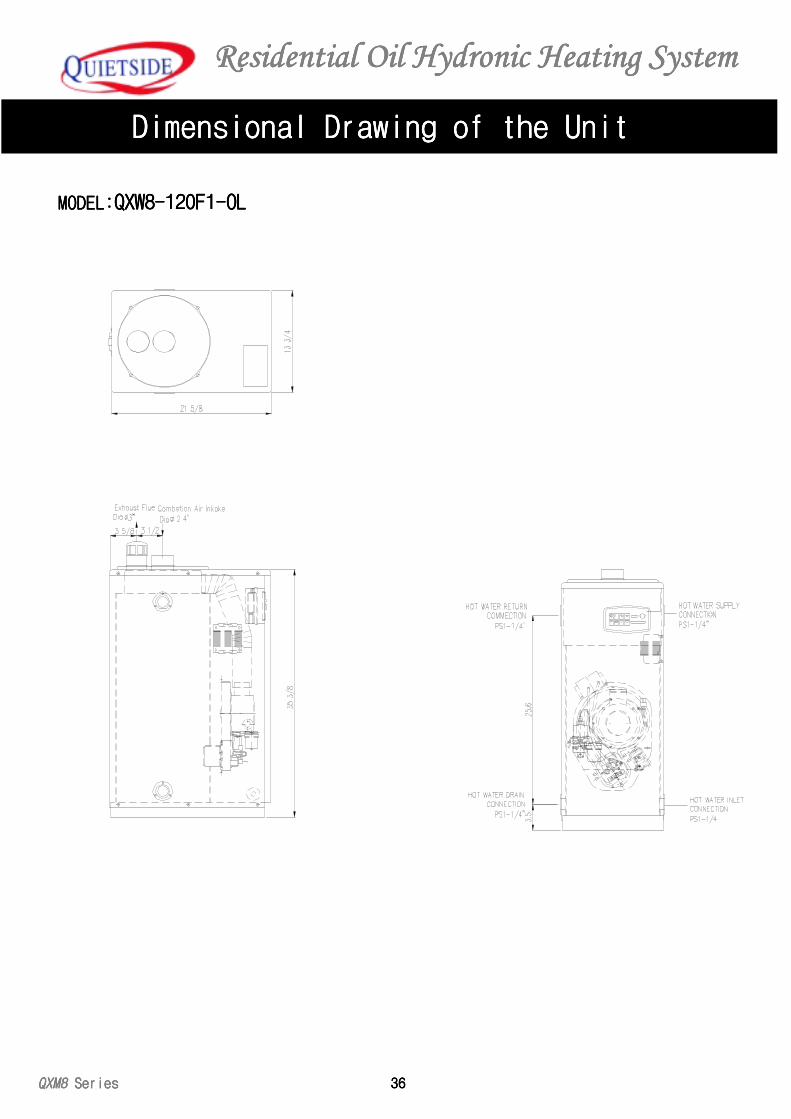
MODELMODELMODELMODEL::::QXW8-120F1-OLQXW8-120F1-OLQXW8-120F1-OLQXW8-120F1-OL
Residential Residential Residential Residential Oil Oil Oil Oil Hydronic Heating SystemHydronic Heating SystemHydronic Heating SystemHydronic Heating System
37373737 QXM8QXM8QXM8QXM8 Series Series Series Series
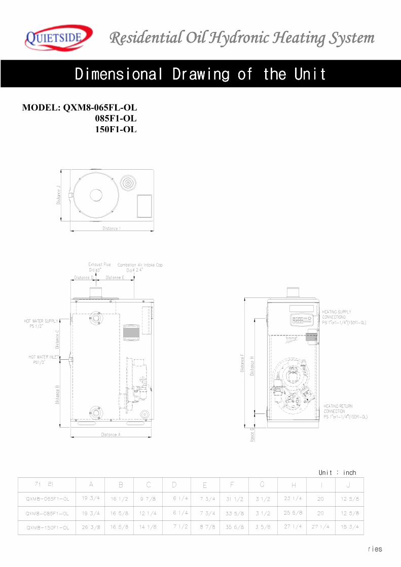
Dimensional Drawing of the UnitDimensional Drawing of the UnitDimensional Drawing of the UnitDimensional Drawing of the Unit
MODEL: QXM8-065FL-OL 085F1-OL 150F1-OL
unit: inch
Unit : inch
Residential Residential Residential Residential Oil Oil Oil Oil Hydronic Heating SystemHydronic Heating SystemHydronic Heating SystemHydronic Heating System
QXM8 QXM8 QXM8 QXM8 Series Series Series Series 38383838
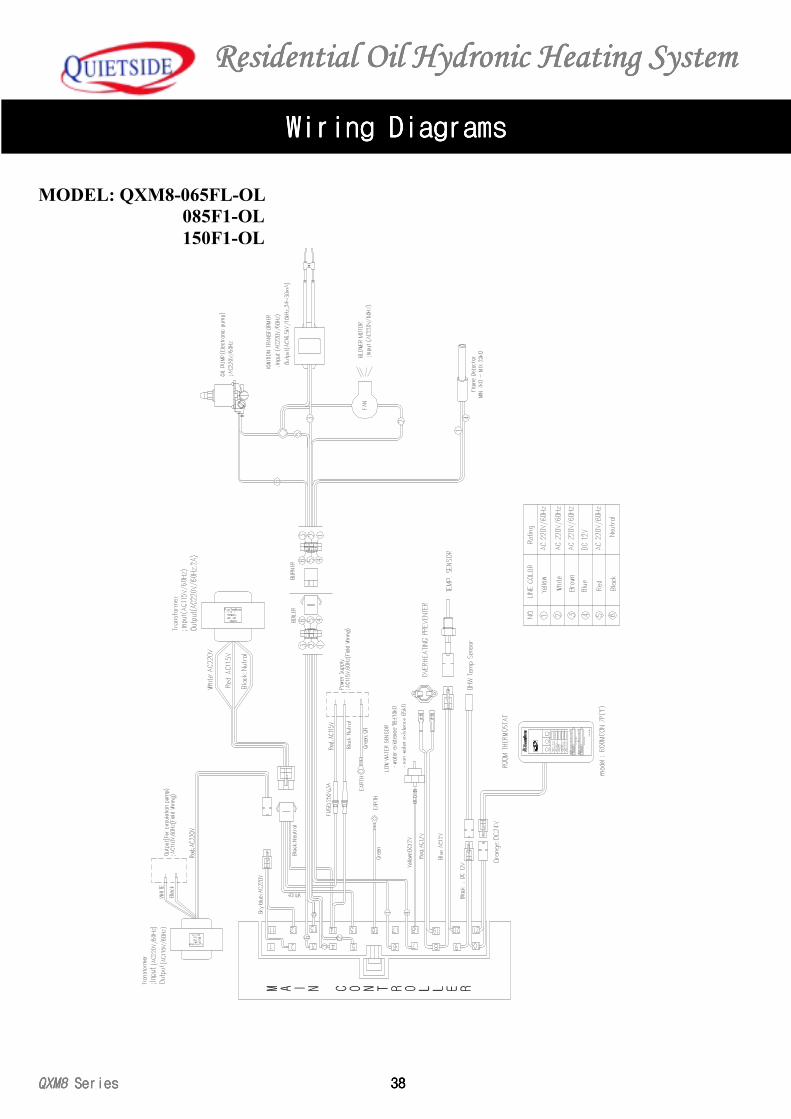
Wiring DiagramWiring DiagramWiring DiagramWiring Diagramssss
MODEL: QXM8-065FL-OL 085F1-OL 150F1-OL
95°
F
HOT
WAT
ER
GOIN
G O
UTTI
MER
41°
F
ROOM
CON
7
REPE
AT T
IMER
2.5
TEM
P CO
NTR
OL
40H
r
THER
MAL
CON
TINU
OUS
POW
EROP
ERAT
ION
REPE
ATCO
NTR
IL
INST
ION
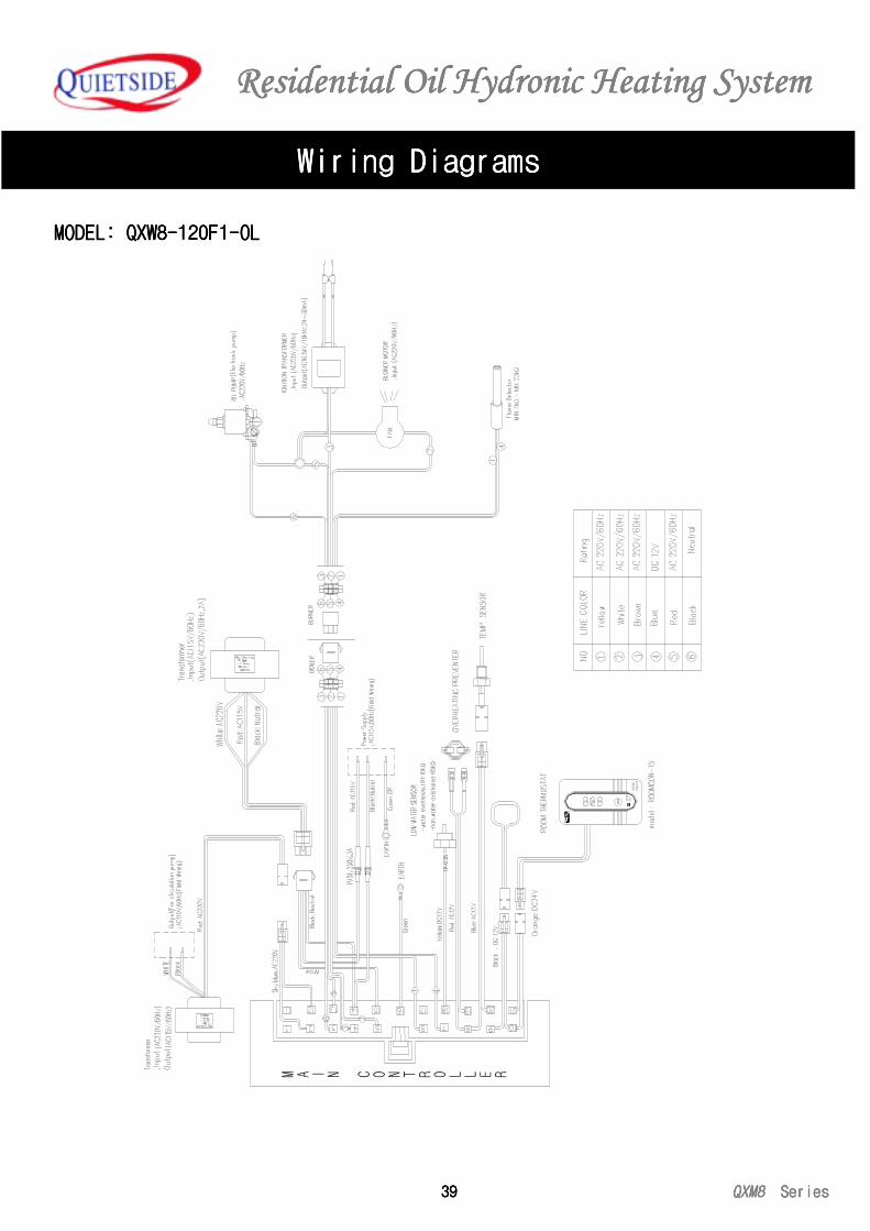
Residential Residential Residential Residential Oil Oil Oil Oil Hydronic Heating SystemHydronic Heating SystemHydronic Heating SystemHydronic Heating System
39393939 QXM8QXM8QXM8QXM8 Series Series Series Series
Wiring DiagramWiring DiagramWiring DiagramWiring Diagramssss
MODEL: QXW8-120F1-OLMODEL: QXW8-120F1-OLMODEL: QXW8-120F1-OLMODEL: QXW8-120F1-OL
CON
-15
ROO
M
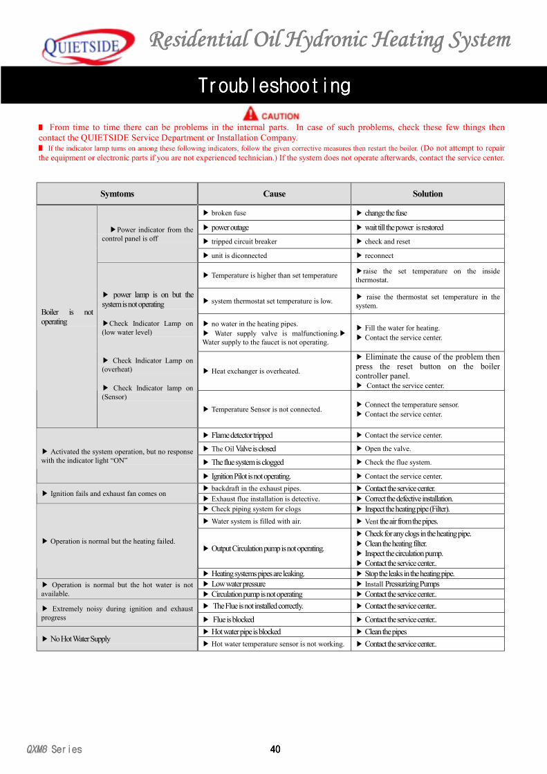
Residential Residential Residential Residential Oil Oil Oil Oil Hydronic Heating SystemHydronic Heating SystemHydronic Heating SystemHydronic Heating System
QXM8 QXM8 QXM8 QXM8 Series Series Series Series 40404040
TroubleshootingTroubleshootingTroubleshootingTroubleshooting
■ From time to time there can be problems in the internal parts. In case of such problems, check these few things thencontact the QUIETSIDE Service Department or Installation Company.■ If the indicator lamp turns on among these following indicators, follow the given corrective measures then restart the boiler. (Do not attempt to repairthe equipment or electronic parts if you are not experienced technician.) If the system does not operate afterwards, contact the service center.
Symtoms Cause Solution
▶ broken fuse ▶ change the fuse
▶ power outage ▶ wait till the power is restored
▶ tripped circuit breaker ▶ check and reset▶Power indicator from the
control panel is off
▶ unit is diconnected ▶ reconnect
▶ Temperature is higher than set temperature ▶raise the set temperature on the insidethermostat.
▶ system thermostat set temperature is low. ▶ raise the thermostat set temperature in thesystem.
▶ no water in the heating pipes.▶ Water supply valve is malfunctioning.▶Water supply to the faucet is not operating.
▶ Fill the water for heating.▶ Contact the service center.
▶ Heat exchanger is overheated.
▶ Eliminate the cause of the problem thenpress the reset button on the boilercontroller panel.▶ Contact the service center.
Boiler is notoperating
▶ power lamp is on but thesystem is not operating
▶Check Indicator Lamp on(low water level)
▶ Check Indicator Lamp on(overheat)
▶ Check Indicator lamp on(Sensor)
▶ Temperature Sensor is not connected. ▶ Connect the temperature sensor.▶ Contact the service center.
▶ Flame detector tripped ▶ Contact the service center.
▶ The Oil Valve is closed ▶ Open the valve.
▶ The flue system is clogged ▶ Check the flue system.▶ Activated the system operation, but no responsewith the indicator light “ON”
▶ Ignition Pilot is not operating. ▶ Contact the service center.▶ backdraft in the exhaust pipes. ▶ Contact the service center.
▶ Ignition fails and exhaust fan comes on▶ Exhaust flue installation is detective. ▶ Correct the defective installation.▶ Check piping system for clogs ▶ Inspect the heating pipe (Filter).▶ Water system is filled with air. ▶ Vent the air from the pipes.
▶ Output Circulation pump is not operating.
▶ Check for any clogs in the heating pipe.▶ Clean the heating filter.▶ Inspect the circulation pump.▶ Contact the service center..
▶ Operation is normal but the heating failed.
▶ Heating systems pipes are leaking. ▶ Stop the leaks in the heating pipe.▶ Low water pressure ▶ Install Pressurizing Pumps▶ Operation is normal but the hot water is not
available. ▶ Circulation pump is not operating ▶ Contact the service center..▶ The Flue is not installed correctly. ▶ Contact the service center..▶ Extremely noisy during ignition and exhaust
progress ▶ Flue is blocked ▶ Contact the service center..▶ Hot water pipe is blocked ▶ Clean the pipes
▶ No Hot Water Supply▶ Hot water temperature sensor is not working. ▶ Contact the service center..
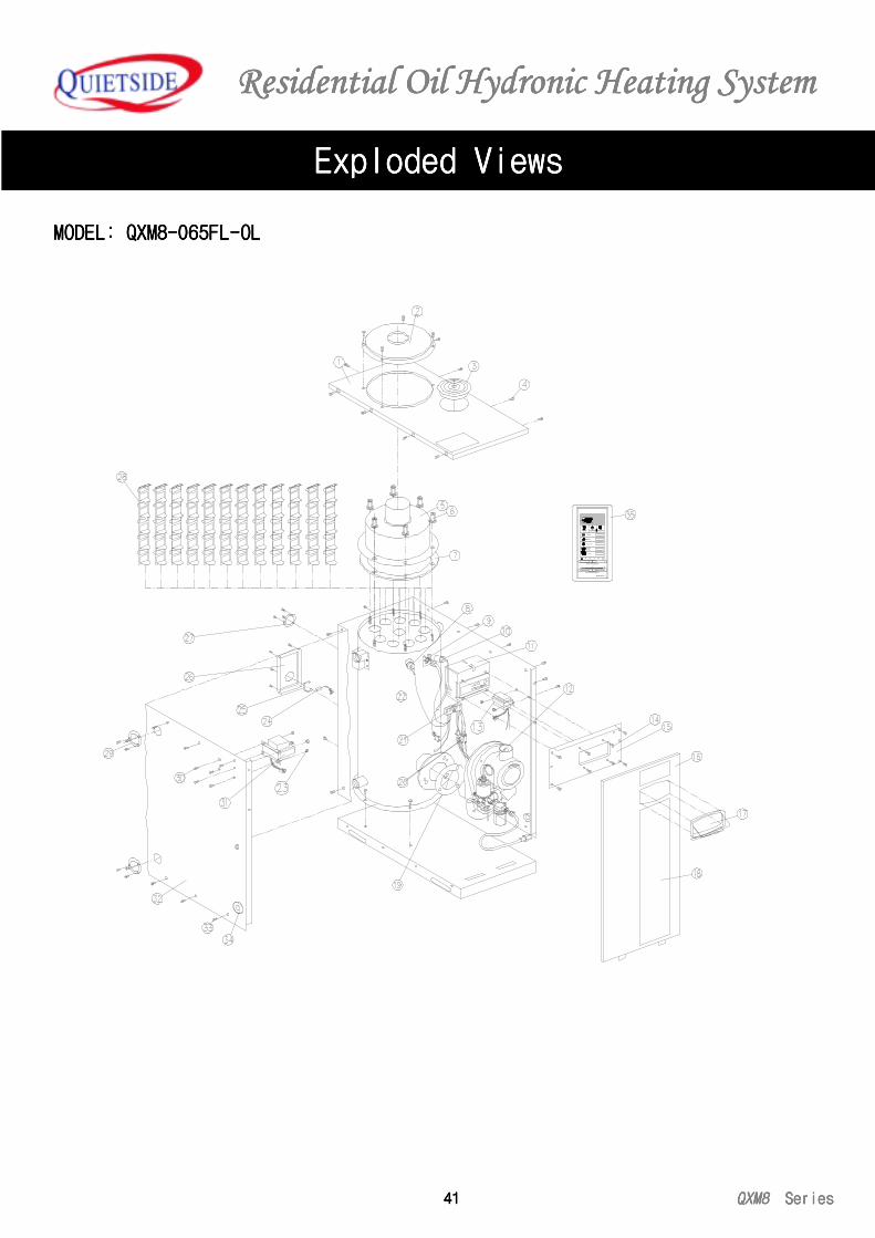
Residential Residential Residential Residential Oil Oil Oil Oil Hydronic Heating SystemHydronic Heating SystemHydronic Heating SystemHydronic Heating System
41414141 QXM8QXM8QXM8QXM8 Series Series Series Series
MODEL: QXM8-065FL-OLMODEL: QXM8-065FL-OLMODEL: QXM8-065FL-OLMODEL: QXM8-065FL-OL
Exploded ViewsExploded ViewsExploded ViewsExploded Views
80
RoomCon 7
Unoccupied Program
W int er
5040
4
60 70
2.5
Room Temperature
Summ er
Timer ON
FreezeGuard
TURBO
F90 °
Hr0
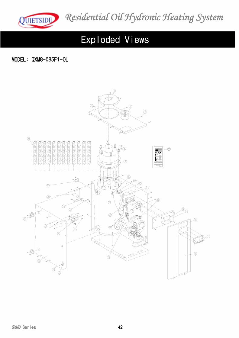
Residential Residential Residential Residential Oil Oil Oil Oil Hydronic Heating SystemHydronic Heating SystemHydronic Heating SystemHydronic Heating System
QXM8 QXM8 QXM8 QXM8 Series Series Series Series 42424242
Exploded ViewsExploded ViewsExploded ViewsExploded Views
MODEL: QXM8-085F1-OLMODEL: QXM8-085F1-OLMODEL: QXM8-085F1-OLMODEL: QXM8-085F1-OL
80
RoomCon 7
Unoccupied Program
Winter
5040
4
60 70
2.5
Room Temperature
Summer
Timer ON
FreezeGuard
TURBO
F90°
Hr0
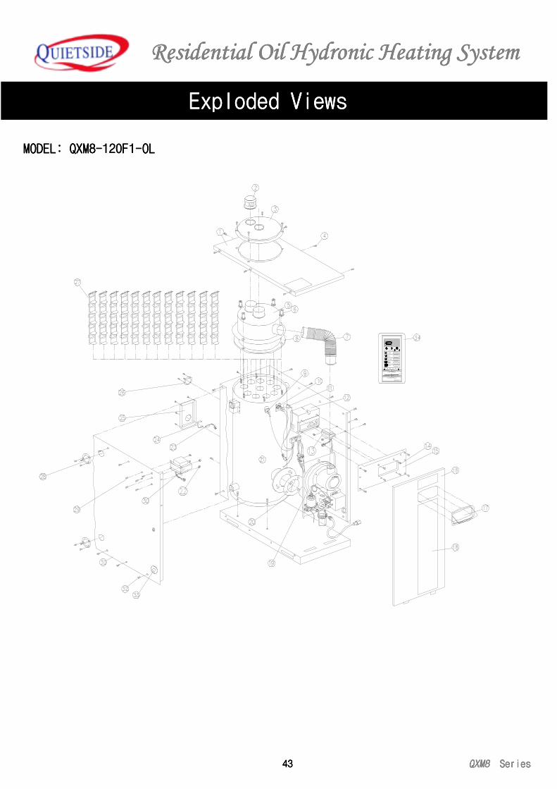
Residential Residential Residential Residential Oil Oil Oil Oil Hydronic Heating SystemHydronic Heating SystemHydronic Heating SystemHydronic Heating System
43434343 QXM8QXM8QXM8QXM8 Series Series Series Series
Exploded ViewsExploded ViewsExploded ViewsExploded Views
MODEL: QXM8-120F1-OLMODEL: QXM8-120F1-OLMODEL: QXM8-120F1-OLMODEL: QXM8-120F1-OL
80
Room Con 7
Unoccup ied P rogram
Winter
5040
4
60 70
2.5
Room Temp erature
Summer
Timer ON
FreezeGuard
TURBO
F90°
Hr0
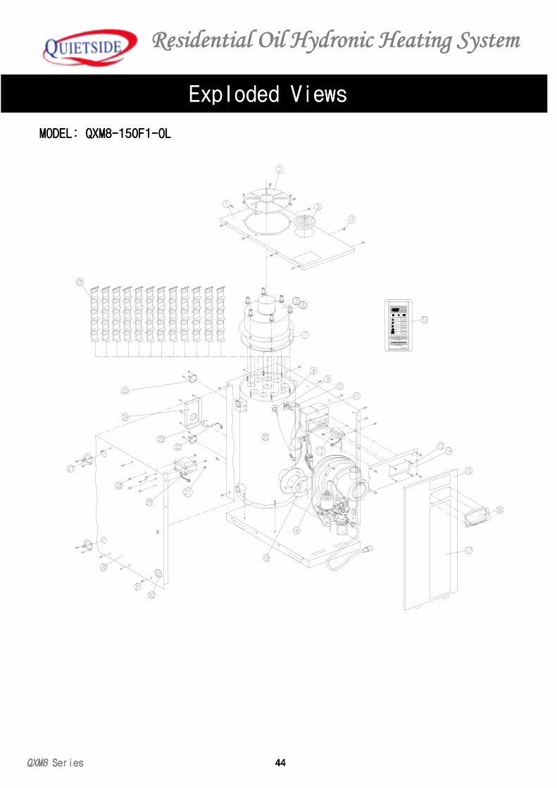
Residential Residential Residential Residential Oil Oil Oil Oil Hydronic Heating SystemHydronic Heating SystemHydronic Heating SystemHydronic Heating System
QXM8 QXM8 QXM8 QXM8 Series Series Series Series 44444444
80
RoomCon 7
Unoccupied Program
Winter
5040
4
60 70
2.5
Room Temperature
Summer
Timer ON
FreezeGuard
TURBO
F90°
Hr0
MODEL: QXM8-150F1-OLMODEL: QXM8-150F1-OLMODEL: QXM8-150F1-OLMODEL: QXM8-150F1-OL
Exploded ViewsExploded ViewsExploded ViewsExploded Views
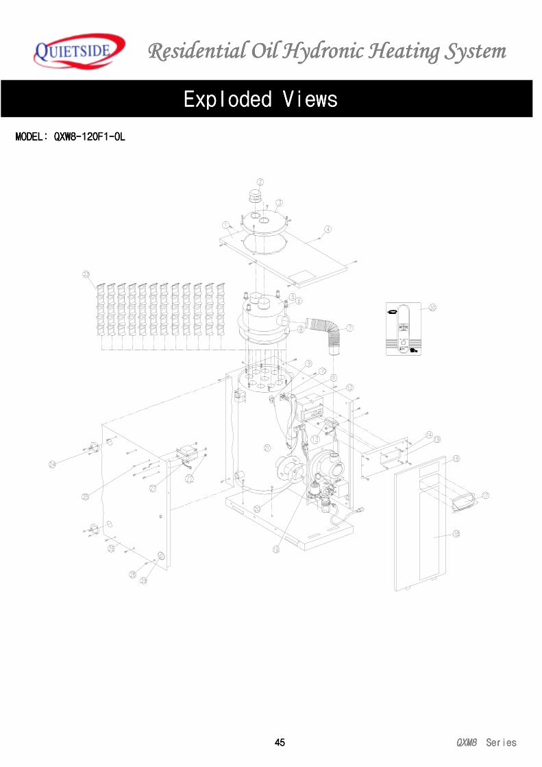
Residential Residential Residential Residential Oil Oil Oil Oil Hydronic Heating SystemHydronic Heating SystemHydronic Heating SystemHydronic Heating System
45454545 QXM8QXM8QXM8QXM8 Series Series Series Series
Exploded ViewsExploded ViewsExploded ViewsExploded Views
UIETSIDEQ
MODEL: QXW8-120F1-OLMODEL: QXW8-120F1-OLMODEL: QXW8-120F1-OLMODEL: QXW8-120F1-OL
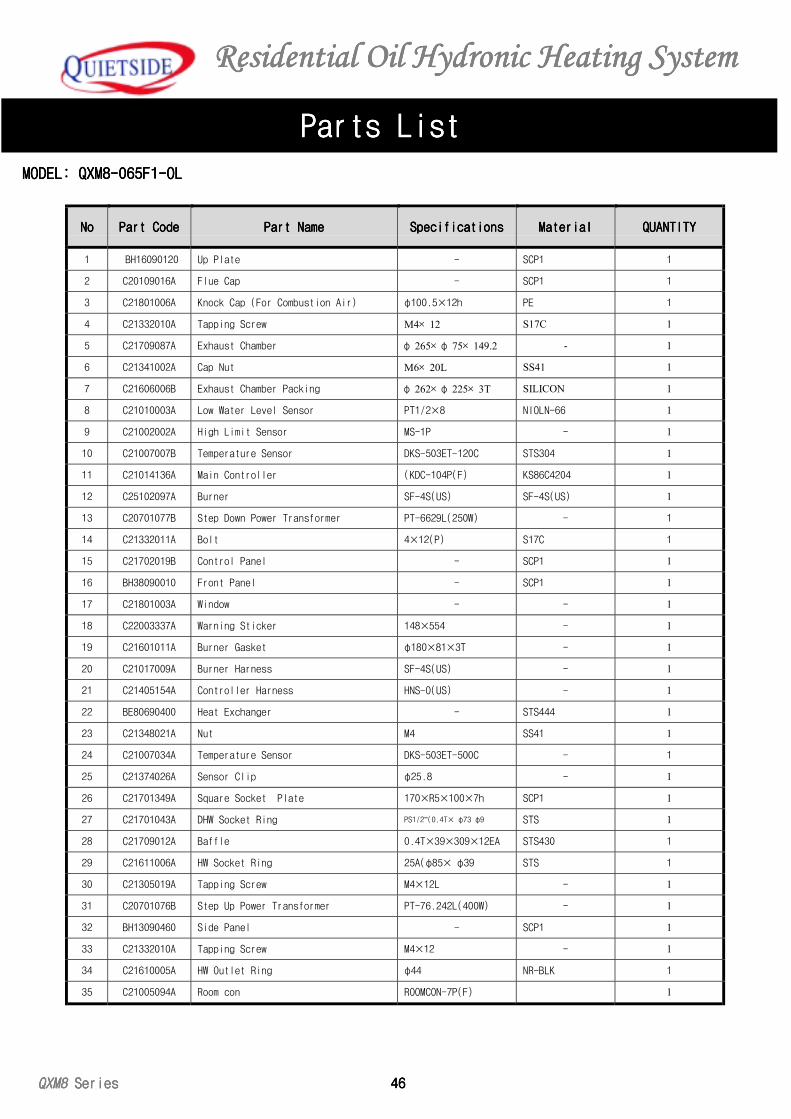
Residential Residential Residential Residential Oil Oil Oil Oil Hydronic Heating SystemHydronic Heating SystemHydronic Heating SystemHydronic Heating System
QXM8 QXM8 QXM8 QXM8 Series Series Series Series 46464646
Parts ListParts ListParts ListParts List
MODEL: QXM8-065F1-OLMODEL: QXM8-065F1-OLMODEL: QXM8-065F1-OLMODEL: QXM8-065F1-OL
NoNoNoNo Part CodePart CodePart CodePart Code Part NamePart NamePart NamePart Name SpecificationsSpecificationsSpecificationsSpecifications MaterialMaterialMaterialMaterial QUANTITYQUANTITYQUANTITYQUANTITY
1 BH16090120 Up Plate - SCP1 1
2 C20109016A Flue Cap - SCP1 1
3 C21801006A Knock Cap (For Combustion Air) φ100.5×12h PE 1
4 C21332010A Tapping Screw M4× 12 S17C 1
5 C21709087A Exhaust Chamber φ 265× φ 75× 149.2 - 1
6 C21341002A Cap Nut M6× 20L SS41 1
7 C21606006B Exhaust Chamber Packing φ 262× φ 225× 3T SILICON 1
8 C21010003A Low Water Level Sensor PT1/2×8 NIOLN-66 1
9 C21002002A High Limit Sensor MS-1P - 1
10 C21007007B Temperature Sensor DKS-503ET-120C STS304 1
11 C21014136A Main Controller (KDC-104P(F) KS86C4204 1
12 C25102097A Burner SF-4S(US) SF-4S(US) 1
13 C20701077B Step Down Power Transformer PT-6629L(250W) - 1
14 C21332011A Bolt 4×12(P) S17C 1
15 C21702019B Control Panel - SCP1 1
16 BH38090010 Front Panel - SCP1 1
17 C21801003A Window - - 1
18 C22003337A Warning Sticker 148×554 - 1
19 C21601011A Burner Gasket φ180×81×3T - 1
20 C21017009A Burner Harness SF-4S(US) - 1
21 C21405154A Controller Harness HNS-O(US) - 1
22 BE80690400 Heat Exchanger - STS444 1
23 C21348021A Nut M4 SS41 1
24 C21007034A Temperature Sensor DKS-503ET-500C - 1
25 C21374026A Sensor Clip φ25.8 - 1
26 C21701349A Square Socket Plate 170×R5×100×7h SCP1 1
27 C21701043A DHW Socket Ring PS1/2”(0.4T× φ73 φ9 STS 1
28 C21709012A Baffle 0.4T×39×309×12EA STS430 1
29 C21611006A HW Socket Ring 25A(φ85× φ39 STS 1
30 C21305019A Tapping Screw M4×12L - 1
31 C20701076B Step Up Power Transformer PT-76.242L(400W) - 1
32 BH13090460 Side Panel - SCP1 1
33 C21332010A Tapping Screw M4×12 - 1
34 C21610005A HW Outlet Ring φ44 NR-BLK 1
35 C21005094A Room con ROOMCON-7P(F) 1
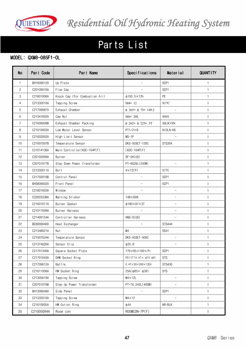
Residential Residential Residential Residential Oil Oil Oil Oil Hydronic Heating SystemHydronic Heating SystemHydronic Heating SystemHydronic Heating System
47474747 QXM8QXM8QXM8QXM8 Series Series Series Series
Parts ListParts ListParts ListParts ListMODEL: QXM8-085F1-OLMODEL: QXM8-085F1-OLMODEL: QXM8-085F1-OLMODEL: QXM8-085F1-OL
NoNoNoNo Part CodePart CodePart CodePart Code Part NamePart NamePart NamePart Name SpecificationsSpecificationsSpecificationsSpecifications MaterialMaterialMaterialMaterial QUANTITYQUANTITYQUANTITYQUANTITY
1 BH16090120 Up Plate - SCP1 1
2 C20109016A Flue Cap - SCP1 1
3 C21801006A Knock Cap (For Combustion Air) φ100.5×12h PE 1
4 C21332010A Tapping Screw M4× 12 S17C 1
5 C21709087A Exhaust Chamber φ 265× φ 75× 149.2 - 1
6 C21341002A Cap Nut M6× 20L SS41 1
7 C21606006B Exhaust Chamber Packing φ 262× φ 225× 3T SILICON 1
8 C21010003A Low Water Level Sensor PT1/2×8 NIOLN-66 1
9 C21002002A High Limit Sensor MS-1P - 1
10 C21007007B Temperature Sensor DKS-503ET-120C STS304 1
11 C21014136A Main Controller(KDC-104P(F) (KDC-104P(F) 1
12 C25102099A Burner SF-5H(US) 1
13 C20701077B Step Down Power Transformer PT-6629L(250W) - 1
14 C21332011A Bolt 4×12(P) S17C 1
15 C21702019B Control Panel - SCP1 1
16 BH38090020 Front Panel - SCP1 1
17 C21801003A Window - - 1
18 C22003338A Warning Sticker 148×608 - 1
19 C21601011A Burner Gasket φ180×81×3T - 1
20 C21017009A Burner Harness - - 1
21 C21405154A Controller Harness HNS-O(US) - 1
22 BE80690400 Heat Exchanger - STS444 1
23 C21348021A Nut M4 SS41 1
24 C21007034A Temperature Sensor DKS-503ET-500C - 1
25 C21374026A Sensor Clip φ25.8 - 1
26 C21701349A Square Socket Plate 170×R5×100×7h SCP1 1
27 C21701043A DHW Socket Ring PS1/2”(0.4T× φ73 φ9) STS 1
28 C21709012A Baffle 0.4T×39×309×12EA STS430 1
29 C21611006A HW Socket Ring 25A(φ85× φ39) STS 1
30 C21305019A Tapping Screw M4×12L - 1
31 C20701076B Step Up Power Transformer PT-76.242L(400W) - 1
32 BH13090460 Side Panel - SCP1 1
33 C21332010A Tapping Screw M4×12 - 1
34 C21610005A HW Outlet Ring φ44 NR-BLK 1
35 C21005094A Room con ROOMCON-7P(F) 1
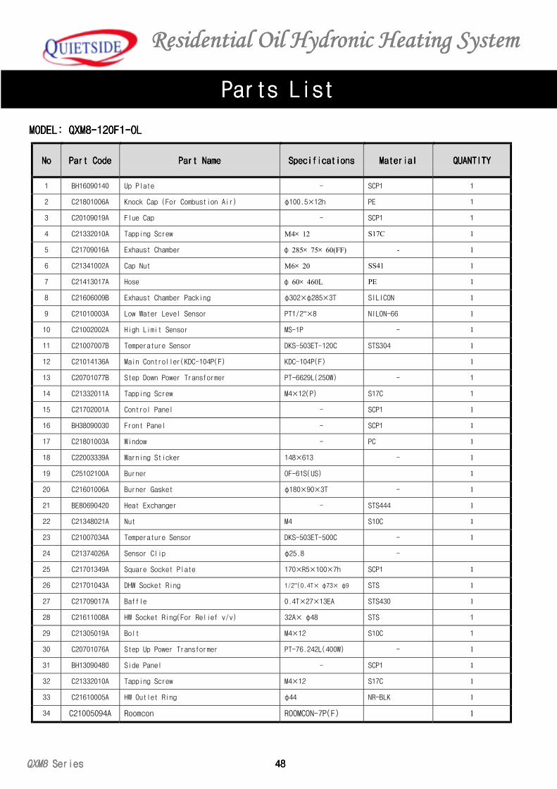
Residential Residential Residential Residential Oil Oil Oil Oil Hydronic Heating SystemHydronic Heating SystemHydronic Heating SystemHydronic Heating System
QXM8 QXM8 QXM8 QXM8 Series Series Series Series 48484848
Parts ListParts ListParts ListParts List
NoNoNoNo Part CodePart CodePart CodePart Code Part NamePart NamePart NamePart Name SpecificationsSpecificationsSpecificationsSpecifications MaterialMaterialMaterialMaterial QUANTITYQUANTITYQUANTITYQUANTITY
1 BH16090140 Up Plate - SCP1 1
2 C21801006A Knock Cap (For Combustion Air) φ100.5×12h PE 1
3 C20109019A Flue Cap - SCP1 1
4 C21332010A Tapping Screw M4× 12 S17C 1
5 C21709016A Exhaust Chamber φ 285× 75× 60(FF) - 1
6 C21341002A Cap Nut M6× 20 SS41 1
7 C21413017A Hose φ 60× 460L PE 1
8 C21606009B Exhaust Chamber Packing φ302×φ285×3T SILICON 1
9 C21010003A Low Water Level Sensor PT1/2”×8 NILON-66 1
10 C21002002A High Limit Sensor MS-1P - 1
11 C21007007B Temperature Sensor DKS-503ET-120C STS304 1
12 C21014136A Main Controller(KDC-104P(F) KDC-104P(F) 1
13 C20701077B Step Down Power Transformer PT-6629L(250W) - 1
14 C21332011A Tapping Screw M4×12(P) S17C 1
15 C21702001A Control Panel - SCP1 1
16 BH38090030 Front Panel - SCP1 1
17 C21801003A Window - PC 1
18 C22003339A Warning Sticker 148×613 - 1
19 C25102100A Burner OF-61S(US) 1
20 C21601006A Burner Gasket φ180×90×3T - 1
21 BE80690420 Heat Exchanger - STS444 1
22 C21348021A Nut M4 S10C 1
23 C21007034A Temperature Sensor DKS-503ET-500C - 1
24 C21374026A Sensor Clip φ25.8 -
25 C21701349A Square Socket Plate 170×R5×100×7h SCP1 1
26 C21701043A DHW Socket Ring 1/2”(0.4T× φ73× φ9 STS 1
27 C21709017A Baffle 0.4T×27×13EA STS430 1
28 C21611008A HW Socket Ring(For Relief v/v) 32A× φ48 STS 1
29 C21305019A Bolt M4×12 S10C 1
30 C20701076A Step Up Power Transformer PT-76.242L(400W) - 1
31 BH13090480 Side Panel - SCP1 1
32 C21332010A Tapping Screw M4×12 S17C 1
33 C21610005A HW Outlet Ring φ44 NR-BLK 1
34 C21005094A Roomcon ROOMCON-7P(F) 1
MODEL: QXM8-120F1-OLMODEL: QXM8-120F1-OLMODEL: QXM8-120F1-OLMODEL: QXM8-120F1-OL
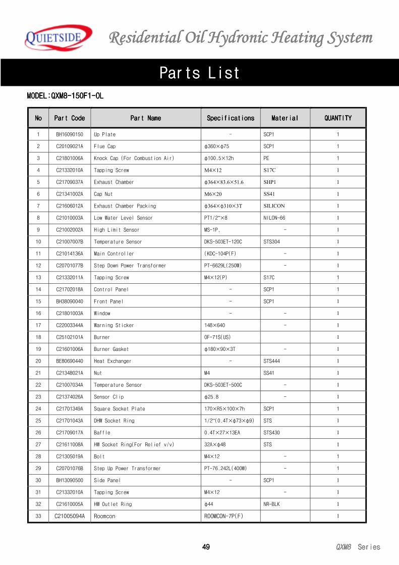
Residential Residential Residential Residential Oil Oil Oil Oil Hydronic Heating SystemHydronic Heating SystemHydronic Heating SystemHydronic Heating System
49494949 QXM8QXM8QXM8QXM8 Series Series Series Series
Parts ListParts ListParts ListParts List
NoNoNoNo Part CodePart CodePart CodePart Code Part NamePart NamePart NamePart Name SpecificationsSpecificationsSpecificationsSpecifications MaterialMaterialMaterialMaterial QUANTITYQUANTITYQUANTITYQUANTITY
1 BH16090150 Up Plate - SCP1 1
2 C20109021A Flue Cap φ360×φ75 SCP1 1
3 C21801006A Knock Cap (For Combustion Air) φ100.5×12h PE 1
4 C21332010A Tapping Screw M4×12 S17C 1
5 C21709037A Exhaust Chamber φ364×83.6×51.6 SHP1 1
6 C21341002A Cap Nut M6×20 SS41 1
7 C21606012A Exhaust Chamber Packing φ364×φ310×3T SILICON 1
8 C21010003A Low Water Level Sensor PT1/2”×8 NILON-66 1
9 C21002002A High Limit Sensor MS-1P, - 1
10 C21007007B Temperature Sensor DKS-503ET-120C STS304 1
11 C21014136A Main Controller (KDC-104P(F) - 1
12 C20701077B Step Down Power Transformer PT-6629L(250W) - 1
13 C21332011A Tapping Screw M4×12(P) S17C 1
14 C21702018A Control Panel - SCP1 1
15 BH38090040 Front Panel - SCP1 1
16 C21801003A Window - - 1
17 C22003344A Warning Sticker 148×640 - 1
18 C25102101A Burner OF-71S(US) 1
19 C21601006A Burner Gasket φ180×90×3T - 1
20 BE80690440 Heat Exchanger - STS444 1
21 C21348021A Nut M4 SS41 1
22 C21007034A Temperature Sensor DKS-503ET-500C - 1
23 C21374026A Sensor Clip φ25.8 - 1
24 C21701349A Square Socket Plate 170×R5×100×7h SCP1 1
25 C21701043A DHW Socket Ring 1/2”(0.4T×φ73×φ9) STS 1
26 C21709017A Baffle 0.4T×27×13EA STS430 1
27 C21611008A HW Socket Ring(For Relief v/v) 32A×φ48 STS 1
28 C21305019A Bolt M4×12 - 1
29 C20701076B Step Up Power Transformer PT-76.242L(400W) - 1
30 BH13090500 Side Panel - SCP1 1
31 C21332010A Tapping Screw M4×12 - 1
32 C21610005A HW Outlet Ring φ44 NR-BLK 1
33 C21005094A Roomcon ROOMCON-7P(F) 1
MODELMODELMODELMODEL:QXM8-150F1-OL:QXM8-150F1-OL:QXM8-150F1-OL:QXM8-150F1-OL
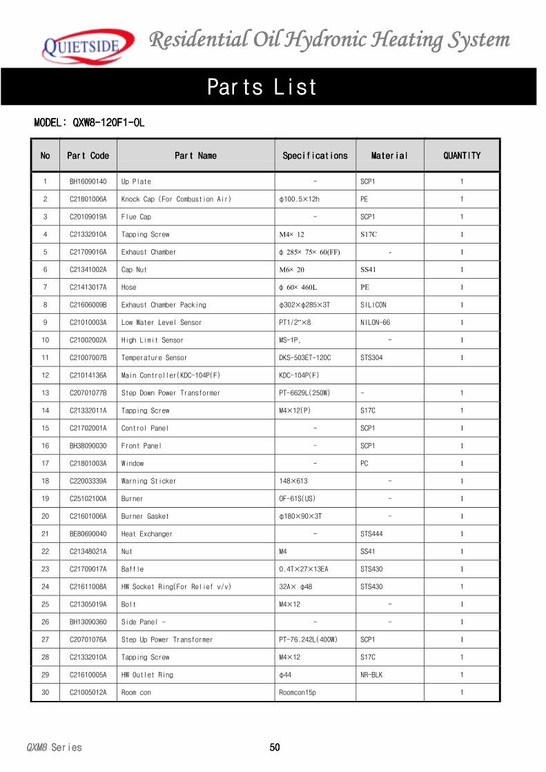
Residential Residential Residential Residential Oil Oil Oil Oil Hydronic Heating SystemHydronic Heating SystemHydronic Heating SystemHydronic Heating System
QXM8 QXM8 QXM8 QXM8 Series Series Series Series 50505050
Parts ListParts ListParts ListParts List
NoNoNoNo Part CodePart CodePart CodePart Code Part NamePart NamePart NamePart Name SpecificationsSpecificationsSpecificationsSpecifications MaterialMaterialMaterialMaterial QUANTITYQUANTITYQUANTITYQUANTITY
1 BH16090140 Up Plate - SCP1 1
2 C21801006A Knock Cap (For Combustion Air) φ100.5×12h PE 1
3 C20109019A Flue Cap - SCP1 1
4 C21332010A Tapping Screw M4× 12 S17C 1
5 C21709016A Exhaust Chamber φ 285× 75× 60(FF) - 1
6 C21341002A Cap Nut M6× 20 SS41 1
7 C21413017A Hose φ 60× 460L PE 1
8 C21606009B Exhaust Chamber Packing φ302×φ285×3T SILICON 1
9 C21010003A Low Water Level Sensor PT1/2”×8 NILON-66 1
10 C21002002A High Limit Sensor MS-1P, - 1
11 C21007007B Temperature Sensor DKS-503ET-120C STS304 1
12 C21014136A Main Controller(KDC-104P(F) KDC-104P(F)
13 C20701077B Step Down Power Transformer PT-6629L(250W) - 1
14 C21332011A Tapping Screw M4×12(P) S17C 1
15 C21702001A Control Panel - SCP1 1
16 BH38090030 Front Panel - SCP1 1
17 C21801003A Window - PC 1
18 C22003339A Warning Sticker 148×613 - 1
19 C25102100A Burner OF-61S(US) - 1
20 C21601006A Burner Gasket φ180×90×3T - 1
21 BE80690040 Heat Exchanger - STS444 1
22 C21348021A Nut M4 SS41 1
23 C21709017A Baffle 0.4T×27×13EA STS430 1
24 C21611008A HW Socket Ring(For Relief v/v) 32A× φ48 STS430 1
25 C21305019A Bolt M4×12 - 1
26 BH13090360 Side Panel - - - 1
27 C20701076A Step Up Power Transformer PT-76.242L(400W) SCP1 1
28 C21332010A Tapping Screw M4×12 S17C 1
29 C21610005A HW Outlet Ring φ44 NR-BLK 1
30 C21005012A Room con Roomcon15p 1
MODEL: QXW8-120F1-OLMODEL: QXW8-120F1-OLMODEL: QXW8-120F1-OLMODEL: QXW8-120F1-OL
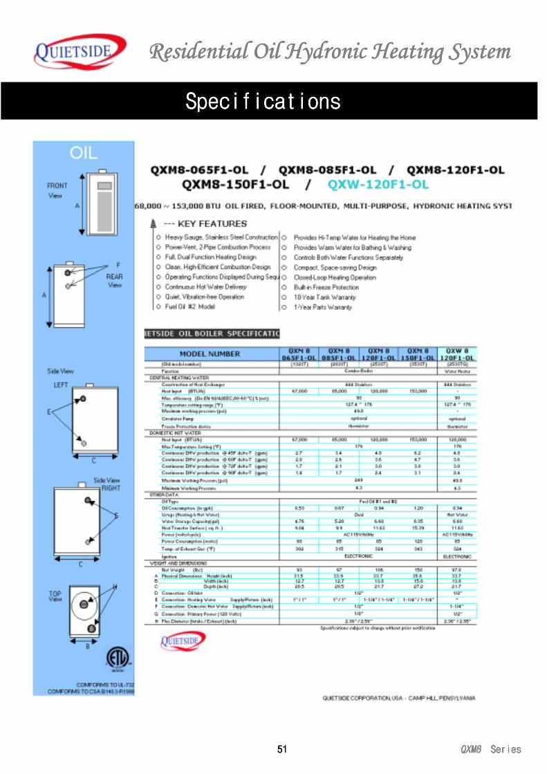
Residential Residential Residential Residential Oil Oil Oil Oil Hydronic Heating SystemHydronic Heating SystemHydronic Heating SystemHydronic Heating System
51515151 QXM8QXM8QXM8QXM8 Series Series Series Series
SpecificationsSpecificationsSpecificationsSpecifications

Printed in Korea 2002 Part No. . C22005123A Rev.1.0
QUIETSIDE CORPORATIONQUIETSIDE CORPORATIONQUIETSIDE CORPORATIONQUIETSIDE CORPORATION
North American Sales Office:
2865 Pellisier Place Whittier, CA 90601
Regional Distribution Office:
4410, Industrial Park Rd. Camp Hill, PA 17011
www.quietside.com
COMFORMS TO UL-732COMFORMS TO UL-732COMFORMS TO UL-732COMFORMS TO UL-732
COMFORMS TO CSA B140.3-R1998COMFORMS TO CSA B140.3-R1998COMFORMS TO CSA B140.3-R1998COMFORMS TO CSA B140.3-R1998