residual current protection unit … abb sace division rcq020 resi dual current protection unit...
TRANSCRIPT

2
ABB SACE Division RCQ020 residual current protection unit 1SDH000708R0001 L5047 EN
RESIDUAL CURRENT PROTECTION UNIT RCQ020/A and RCQ020/P

INDEX
1. SAFETY NOTES..................................................................................................................................................... 21.1. Notes for dielectric strength tests...................................................................................................... 2
2. OVERVIEW ............................................................................................................................................................. 32.1. General considerations ..................................................................................................................... 3
2.1.1. Functional basics .................................................................................................................... 32.1.2. Available versions ................................................................................................................... 3
2.2. References ........................................................................................................................................ 4
3. USER INTERFACE ................................................................................................................................................ 53.1. Front view ......................................................................................................................................... 5
3.1.1. RCQ020/A .............................................................................................................................. 53.1.2. RCQ020/P .............................................................................................................................. 63.1.3. Amperometric selector ............................................................................................................ 63.1.4. Chronometric selector ............................................................................................................. 63.1.5. Signalling LEDs ...................................................................................................................... 7
3.1.5.1. FAULT LED ............................................................................................................... 73.1.5.1.1. RCQ020/A .................................................................................................... 73.1.5.1.2. RCQ020/P .................................................................................................... 7
3.1.6. Dip-switch ............................................................................................................................... 83.1.7. Push-buttons ........................................................................................................................... 83.1.8. Test connector ........................................................................................................................ 83.1.9. Ledbar ..................................................................................................................................... 8
3.2. Rear view .......................................................................................................................................... 93.2.1. RCQ020/A .............................................................................................................................. 93.2.2. RCQ020/P ............................................................................................................................ 103.2.3. Power supply ........................................................................................................................ 10
3.2.3.1. RCQ020/A ............................................................................................................... 103.2.3.2. RCQ020/P ............................................................................................................... 11
3.2.4. Residual current sensor ........................................................................................................ 113.2.5. Opening devices ................................................................................................................... 133.2.6. RCQ020 inputs and outputs ................................................................................................. 133.2.7. Positive Safety ...................................................................................................................... 14
4. MOUNTING AND INSTALLATION OPERATIONS ..................................................................................... 154.1. Mounting instructions ...................................................................................................................... 15
5. APPLICATION SCENARIOS ............................................................................................................................. 165.1. RCQ020 main connections ............................................................................................................. 16
5.1.1. Standard connection ............................................................................................................. 165.1.1.1. RCQ020/A ............................................................................................................... 165.1.1.2. RCQ020/P ............................................................................................................... 16
5.1.2. Positive Safety wiring ............................................................................................................ 175.1.2.1. RCQ020/A ............................................................................................................... 175.1.2.2. RCQ020/P ............................................................................................................... 17
5.1.3. Selectivity .............................................................................................................................. 185.1.3.1. Amperometric and chronometric selectivity ............................................................. 185.1.3.2. Zone selectivity ........................................................................................................ 18
6. TECHNICAL SPECIFICATIONS ...................................................................................................................... 196.1. Electrical charcteristics ................................................................................................................... 19
6.1.1. Overall data .......................................................................................................................... 196.1.1.1. RCQ020/A ............................................................................................................... 196.1.1.2. RCQ020/P ............................................................................................................... 19
6.1.2. Power supply ........................................................................................................................ 196.1.2.1. RCQ020/A ............................................................................................................... 196.1.2.2. RCQ020/P ............................................................................................................... 19
1
ABB SACE Division RCQ020 residual current protection unit 1SDH000708R0001 L5047 EN

6.1.3. Output relays performances ................................................................................................. 206.1.4. Protection trip characteristics ................................................................................................ 206.1.5. International standards ......................................................................................................... 21
6.2. Mechanical characteristics .............................................................................................................. 216.3. Environment conditions ................................................................................................................... 22
7. TROUBLESHOOTING ........................................................................................................................................ 23
8. ELECTRICAL SCHEMES .................................................................................................................................. 24
1
ABB SACE Division RCQ020 residual current protection unit 1SDH000708R0001 L5047 EN
1 SAFETY NOTES
Read this manual carefully and completely before installing, setting up and operating the RCQ020 unit.
This device should be used by qualified competent personnel only.
If there are doubts about safe use, the unit should be placed out of service to protect it against unintentional use.
Safe use must be assumed to be impossible if:
1. there are visible damages to the unit2. the unit is not operating (for example in the test condition)3. the unit has suffered damages during the transport
Before performing any actions or substitutions, be sure that the operation area has been placed in a safe condition, by removing all the supplies and dangerous voltages.
1.1. Notes for dielectric strength tests
WARNING: This symbol identifies informations on practices, actions and circumstances which may result on injuries or harms to personnel, damage to the unit or economic losses.
WARNING: Dielectric strength tests on the inputs and outputs of the devices considered in this document are not permitted.In case of dielectric tests on the switchboard, disconnect all the wirings from the RCQ020 clamps.
28
ABB SACE Division RCQ020 residual current protection unit 1SDH000708R0001 L5047 2/28

2 OVERVIEW
2.1. General considerations
The RCQ020 is a switchboard residual current protection unit that matches with Low Voltage Tmax (T1 to T7), Emax X1 and XTmax circuit breakers; it performs the residual current protection.
A general system involving the RCQ020 consists of:
• a power supply source
• a residual current sensor (tipically a toroidal current transformer)
• any type of electro-mechanical actuators to force the main circuit breaker opening, such as opening (SOR) or undervoltage (UVR) releases
Furthermore, the RCQ020 unit provides different inputs to command the remote opening of the circuit breaker or perform the positive safety function, ensuring the system is placed in a safe condition even in case of malfunctions or failures.
Figure 1 shows the functional scheme of the system so far described.
Figure 1. Block diagram of the system involving RCQ020 unit
2.1.1. Functional basics
The residual current sensor is placed across the AC main power line: normally, the sum of the vectors related to the current flowing in each conductor is zero, but in case of a leakage current towards ground an unbalancing is produced.
This unbalancing is read by the RCQ020 unit and compared with the residual operating current threshold, In: if the residual current is greater than the 80% of the threshold for at least the non operating time t, the RCQ020 will active the connected coil switch to open the circuit breaker.
Both In and t values can be set by the users, as explained in the following chapter of this document.
The tripped condition lasts until the protection unit is reset, except if the RESET dip-switch is set in AUTO position (see Figure 2 and Figure 3).
2.1.2. Available versions
The RCQ020 family consists of different versions.
The version named RCQ020/A is characterized by a power stage workimg with an AC auxiliary supply source
(see par. 3.2.3.1).
The version named RCQ020/P is supplied by a three-phase plus neutral system
(see par. 3.2.3.2).
From now on, each reference to the RCQ020 unit is intended as common reference to RCQ020/A and RCQ020/P.
28
ABB SACE Division RCQ020 residual current protection unit 1SDH000708R0001 L5047 3/28
2.2. References
This document describes how to install, configure and use the RCQ020 unit.
Detailed informations about the circuit breakers mentioned hereafter can be found considering the following documentation:
• ABB SACE Tmax technical catalog (doc. 1SDC210015D0903)
• ABB SACE X1 technical catalog (doc. 1SDC20009D0902)
• ABB SACE XTmax technical catalog (doc. 1SDC210033D0901)
28
ABB SACE Division RCQ020 residual current protection unit 1SDH000708R0001 L5047 4/28

3 USER INTERFACE
3.1. Front view
3.1.1. RCQ020/A
The front view of the RCQ020/A is shown in Figure 2.
Figure 2. RCQ020/A front view
28
ABB SACE Division RCQ020 residual current protection unit 1SDH000708R0001 L5047 5/28

3.1.2. RCQ020/P
The front view of the RCQ020/A is shown in Figure 3.
Figure 3. RCQ020/P front view
3.1.3. Amperometric selector
This rotary selector manages the level of the residual current threshold In, i.e. the value of the fault current that will force the trip of the protection unit.
All the available values are reported in Table 1.
Table 1. Amperometric selection
3.1.4. Chronometric selector
This rotary selector allows to set the non operating time t of the RCQ020, i.e. the delay before the trip.
The non operating time value can be one of those described in Table 2.
Table 2. Chronometric selection
Trip threshold current, In [A]0.03 0.05 0.1 0.3 0.5 1 3 5 10 30
Non operating time, t [s]0 0.1 0.2 0.3 0.5 0.7 1 2 3 5
Note 1: If the current threshold In is 30mA, the istantaneous time setting will be automatically selected (the chronometric selector position won’t be further considered).
28
ABB SACE Division RCQ020 residual current protection unit 1SDH000708R0001 L5047 6/28

3.1.5. Signalling LEDs
Table 3. Signalling Leds
3.1.5.1 FAULT LED
The FAULT LED is active (ON) or blinking if a malfunction or faulty condition is currently present.
If this is the case, the RCQ020 disables the Positive Safety output because its functionality couldn’t be guaranteed (see par. 3.2.6).
3.1.5.1.1 RCQ020/A
Table 4. FAULT LED behavior for RCQ020/A
3.1.5.1.2 RCQ020/P
Table 5. FAULT LED behavior for RCQ020/P
LED Status Meaning
POWERON (Green) Power supply present and in the correct range
OFF Power supply absent or out of range
FAULTON/Blinking (Red)
Unit not working or not properly configured (see Table 4 and Table 5)
OFF No malfunction or faulty condition is currently present
TRIPPED
ON (Yellow) Residual current protection took place
Blinking Remote opening is active
OFF No residual current protection took place
FAULT LED behavior PTN CODE Meaning
1 blink every 2 seconds PTN1 Internal error
2 blinks every 2 seconds PTN2 Sensor not connected
3 blinks every 2 seconds PTN3 Low power, supply under the low power threshold (see Note 2)
4 blinks every 2 seconds PTN4 Backup protection operation (see Note 3)
Permanently ON PTN0 Watchdog
FAULT LED behavior PTN CODE Meaning
1 blink every 2 seconds PTN1 Internal error
2 blinks every 2 seconds PTN2 Sensor not connected
3 blinks every 2 seconds PTN3 Power supply malfunction
4 blinks every 2 seconds PTN4 Backup protection operation (see Note 3)
Permanently ON PTN0 Watchdog
WARNING: In case an internal error or watchdog condition is detected, contact the ABB SACE customer service.
Note 2: The low power threshold is between 70% and 80% of the rated value.
Note 3: In case the Positive Safety connection is performed (see Figure 10), the backup protection signalling is available; it signals that a residual current is still measured by the RCQ020 even if the Trip Protection output has been activated to open the circuit.
28
ABB SACE Division RCQ020 residual current protection unit 1SDH000708R0001 L5047 7/28
3.1.6. Dip-switch
The RCQ020 is provided with a three-way dip switch selector whose behavior is described in Table 5.
Table 6. Description of the dip switch
3.1.7. Push-buttons
Table 7. Push-buttons description
3.1.8. Test connector
The connector on the front of the unit should be used by ABB skilled personnel only for programming and maintenance purposes.
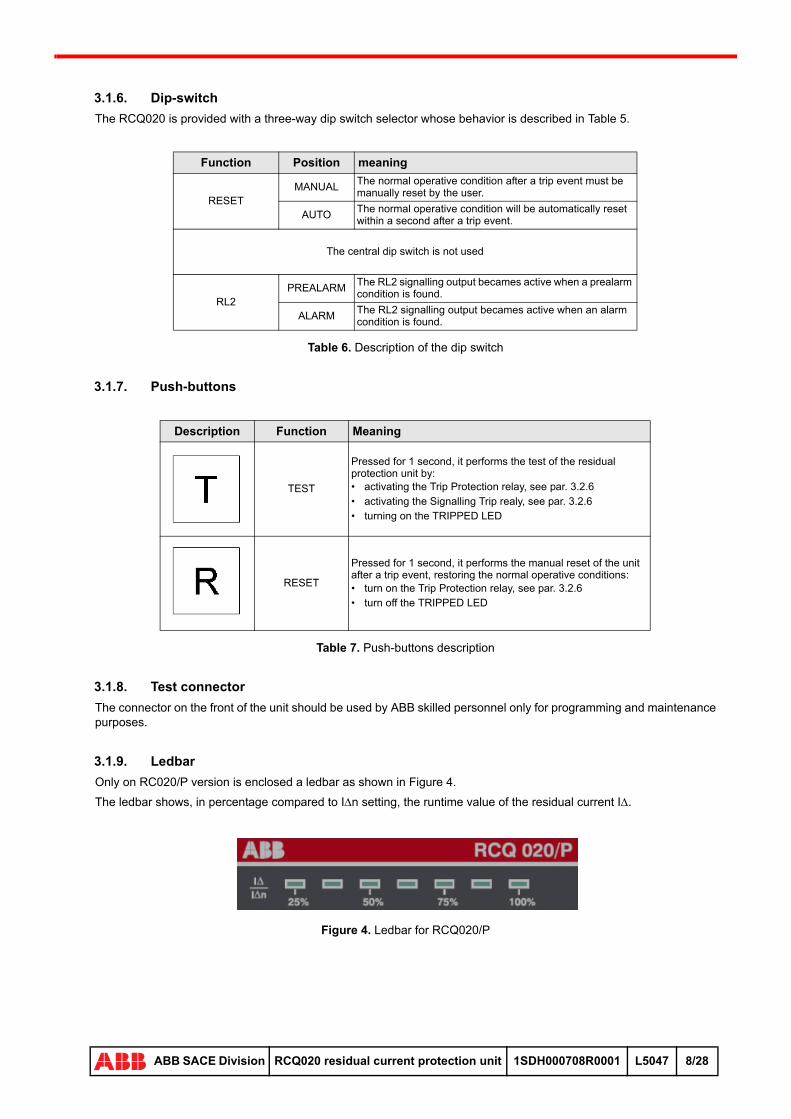
3.1.9. Ledbar
Only on RC020/P version is enclosed a ledbar as shown in Figure 4.
The ledbar shows, in percentage compared to In setting, the runtime value of the residual current I.
Figure 4. Ledbar for RCQ020/P
Function Position meaning
RESETMANUAL
The normal operative condition after a trip event must be manually reset by the user.
AUTOThe normal operative condition will be automatically reset within a second after a trip event.
The central dip switch is not used
RL2PREALARM
The RL2 signalling output becames active when a prealarm condition is found.
ALARMThe RL2 signalling output becames active when an alarm condition is found.
Description Function Meaning
TEST
Pressed for 1 second, it performs the test of the residual protection unit by:• activating the Trip Protection relay, see par. 3.2.6• activating the Signalling Trip realy, see par. 3.2.6• turning on the TRIPPED LED
RESET
Pressed for 1 second, it performs the manual reset of the unit after a trip event, restoring the normal operative conditions:• turn on the Trip Protection relay, see par. 3.2.6• turn off the TRIPPED LED
28
ABB SACE Division RCQ020 residual current protection unit 1SDH000708R0001 L5047 8/28

3.2. Rear view
On the rear of the unit the following connectors are provided:
• power supply
• residual current sensor
• signalling and protection relays
• inputs
3.2.1. RCQ020/A
The rear view of the RCQ020/A is shown in Figure 5.
Figure 5. RCQ020/A rear view
28
ABB SACE Division RCQ020 residual current protection unit 1SDH000708R0001 L5047 9/28
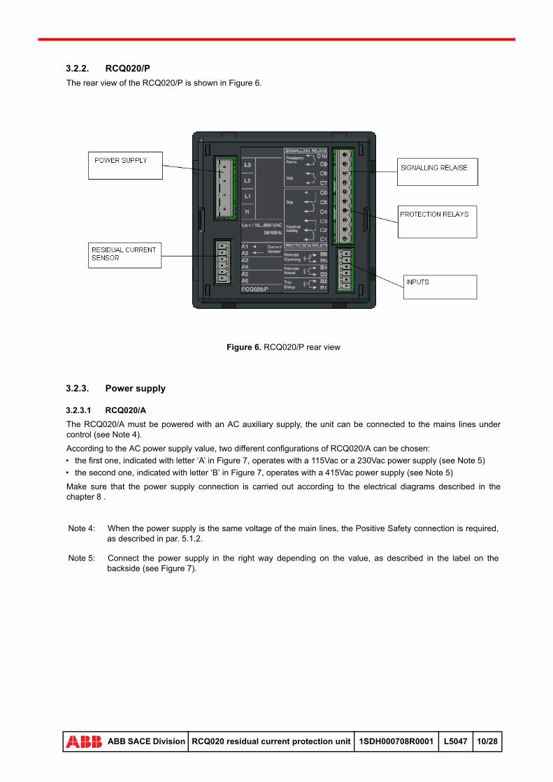
3.2.2. RCQ020/P
The rear view of the RCQ020/P is shown in Figure 6.
Figure 6. RCQ020/P rear view
3.2.3. Power supply
3.2.3.1 RCQ020/A
The RCQ020/A must be powered with an AC auxiliary supply, the unit can be connected to the mains lines under control (see Note 4).
According to the AC power supply value, two different configurations of RCQ020/A can be chosen:
• the first one, indicated with letter ‘A’ in Figure 7, operates with a 115Vac or a 230Vac power supply (see Note 5)
• the second one, indicated with letter ‘B’ in Figure 7, operates with a 415Vac power supply (see Note 5)
Make sure that the power supply connection is carried out according to the electrical diagrams described in the chapter 8 .
Note 4: When the power supply is the same voltage of the main lines, the Positive Safety connection is required, as described in par. 5.1.2.
Note 5: Connect the power supply in the right way depending on the value, as described in the label on the backside (see Figure 7).
28
ABB SACE Division RCQ020 residual current protection unit 1SDH000708R0001 L5047 10/28

Figure 7. Power supply connection for RCQ020/A 115/230Vac and 415Vac versions
3.2.3.2 RCQ020/P
The RCQ020/P must be powered with a three-phase plus neutral supply system collected from the main lines under control (see Note 6).
The way to connect the unit is showed in Figure 8.
Make sure that the power supply connection is carried out according to the electrical diagrams described in the chapter 8 .
Figure 8. Power supply connection for RCQ020/P
3.2.4. Residual current sensor
The residual current sensor detects any imbalance between the currents flowing in the live conductors.
It consists of a closed type toroidal transformer of different sections according to the sensitivity required by the application.
The following table sums up the transformers coupling with the RCQ020.
Nota 6: Connect the supply source as shown on backside label. The label is reproduced on Figure 8.
28
ABB SACE Division RCQ020 residual current protection unit 1SDH000708R0001 L5047 11/28

Table 8. RCQ020 and toroidal residual current sensors
The connection pins 1-2 of the residual current sensor must be left disconnected.
Be careful that the main lines are placed in the centre of the residual current sensor, as shown in the following figure.
Figure 9. Position and fasten the conductors within the residual current sensor
Figure 10. RCQ020 sensors dimensions
Mount the sensor as near as possible to the differential protection unit; the connection cable would be shorter than 15m.
To install the sensor, follow the instructions depicted in Figure 11.
TypeMaximum
ratedcurrent, In
Minimum operativecurrent threshold
InUn Uimp Icw Iw
Connection pins
RCQ020 Residual current sensor
Closed 60mm
250A 30mA
1000Vac 8KVac42KA
for1s
42KAfor
0,5 s
20KAfor1 s
A1-A2(see Figure 5 and Figure 6)
3-4Closed 110mm
400A 30mA
Closed 185mm
800A 100mA
28
ABB SACE Division RCQ020 residual current protection unit 1SDH000708R0001 L5047 12/28

Figure 11. RCQ020 rings mounting instructions
Mount the toroidal transformer (3) across the live conductors of the plant. Fasten the sensor to the bracket (5, 6, 7, 8), then connect it to the differential protection unit.
Be sure that the measuring cables aren’t too close from the power supply lines or any other power conductors and devices that could create noises or interferences.
Use shielded paired cable (BELDEN 3105A type) to connect the sensor and the RCQ020.
Shield must be grounded by RCQ020 side.
The cable resistance must be less than 3.
3.2.5. Opening devices
The Table 9 sums up the available opening devices mating with the RCQ020.
Table 9. Opening devices coupling with the RCQ020
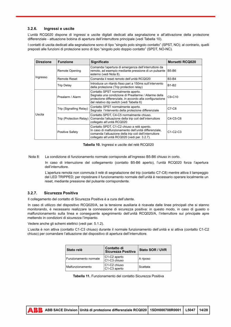
3.2.6. RCQ020 inputs and outputs
The RCQ020 provides different input / output ports for signalling and protection purposes.
For a complete description of the RCQ020 inputs and outputs see Table 10.
The outputs dedicated to signalling have a “single pole single throw” (SPST, NO) contact type, while those for protection are “single pole double throw” (SPDT, NO-NC) contact type.
CB SOR DELAY UVR DELAYT1 Instantaneous Instantaneous
T2 Instantaneous Instantaneous
T3 Instantaneous Instantaneous
T4 Instantaneous Instantaneous
T5 Instantaneous Instantaneous
T6 Instantaneous Instantaneous
T7 Instantaneous 100 ms
X1 Instantaneous 100 ms
XT1 Instantaneous Instantaneous
XT2 Instantaneous Instantaneous
XT3 Instantaneous Instantaneous
XT4 Instantaneous Instantaneous
Note 7: In case of voltages greater than 250Vac, call the ABB SACE customer service.
28
ABB SACE Division RCQ020 residual current protection unit 1SDH000708R0001 L5047 13/28

Table 10. RCQ020 input/output ports
3.2.7. Positive Safety
The wiring of the Positive Safety output must be performed by the user.
It is necessary whenever the RCQ020/A power supply is obtained from the lines under control: in this way, if a fault happens on the main lines and the protection unit turns off, the circuit breaker will be forced to open and the plant will be put in a safe condition.
See the electrical schemes for details (see par. 5.1.2).
The Positive Safety output is not active (C1-C3 is a close contact) during the normal operation and became active (C1-C2 is a close contact) to force the actuation of the opening device.
Table 11. Positive Safety contact operation
Direction Name Description RCQ020 IO clamps
Input
Remote OpeningCommand the circuit breaker opening in case of emergency, by connecting for example an emergency push-button (see Note 8).
B5-B6
Remote Reset Command the remote reset of the RCQ020 B3-B4
Trip DelayAdd a fixed delay of 150ms to the non-operating time selected via rotary selector
B1-B2
Output
Prealarm / AlarmNormally open SPST contact.Indicate a Prealarm / Alarm condition in the RCQ020, according to the dip-switch position (see Table 6)
C9-C10
Trip (Signalling Relay)Normally open SPST contact.Indicate the trip of the RCQ020.
C7-C8
Trip (Protection Relay)SPDT contact, C4-C5 normally close.Command the actuation of the trip coil of the main circuit breaker
C4-C5-C6
Positive Safety
SPDT contact, C1-C2 close when the protection unit is off.Command the actuation of the trip coil of the main circuit breaker when the RCQ020 can’t secure the protection issue (see par. 3.2.7).
C1-C2-C3
Note 8: The normal operation condition is when the B5-B6 input is short circuited.
If the connection between the Remote Opening input and the emergency push-button is interrupted (B5-B6 open) the RCQ020 will force the opening of the main circuit breaker.
The remote opening won’t lead to the activation of the Signalling trip relay (C7-C8) while the TRIPPED LED will start blinking. To restore the normal condition it is necessary to reset the unit by means of the RESET push-button.
Relay status Positive Safety Output SOR / UVR status
Normal operationC1-C2 openC1-C3 close
Steady
MalfunctionC1-C2 closeC1-C3 open
Tripped
28
ABB SACE Division RCQ020 residual current protection unit 1SDH000708R0001 L5047 14/28
4 MOUNTING AND INSTALLATION OPERATIONS
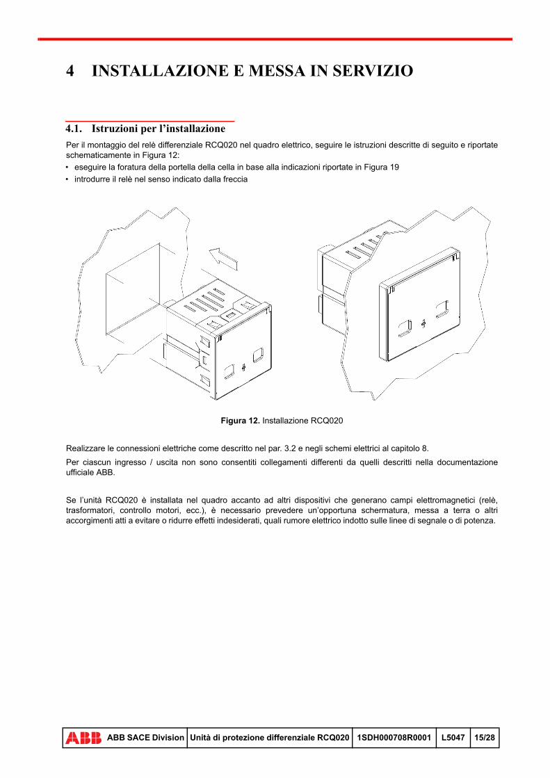
4.1. Mounting instructions
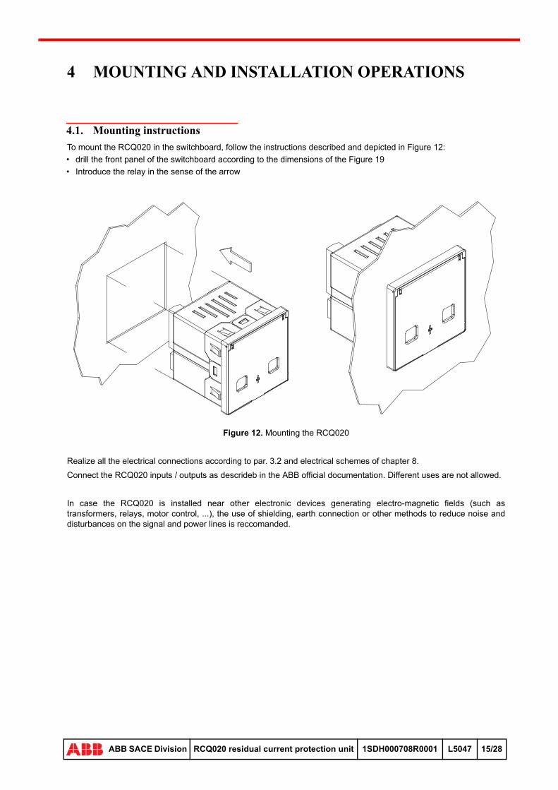
To mount the RCQ020 in the switchboard, follow the instructions described and depicted in Figure 12:
• drill the front panel of the switchboard according to the dimensions of the Figure 19
• Introduce the relay in the sense of the arrow
Figure 12. Mounting the RCQ020
Realize all the electrical connections according to par. 3.2 and electrical schemes of chapter 8.
Connect the RCQ020 inputs / outputs as descrideb in the ABB official documentation. Different uses are not allowed.
In case the RCQ020 is installed near other electronic devices generating electro-magnetic fields (such as transformers, relays, motor control, ...), the use of shielding, earth connection or other methods to reduce noise and disturbances on the signal and power lines is reccomanded.
28
ABB SACE Division RCQ020 residual current protection unit 1SDH000708R0001 L5047 15/28

5 APPLICATION SCENARIOS
5.1. RCQ020 main connections
This section of the manual concerns with the description of the application scenarios involving the RCQ020, focusing on the available connections with the Tmax, Emax X1 and XTmax circuit breakers.
5.1.1. Standard connection
5.1.1.1 RCQ020/A
The standard applicative scenario of RCQ020/A consists of:
• auxiliary power supply
• current sensor
• an electromechanical actuator, such as SOR or UVR, to control the circuit breaker opening
Figure 13. Standard connection for RCQ020/A versions
5.1.1.2 RCQ020/P
The standard applicative scenario of RCQ020/P consists of:
• three-phase plus neutral power supply
• current sensor
• an electromechanical actuator, such as SOR or UVR, to control the circuit breaker opening
Figure 14. Standard connection for RCQ020/P
28
ABB SACE Division RCQ020 residual current protection unit 1SDH000708R0001 L5047 16/28
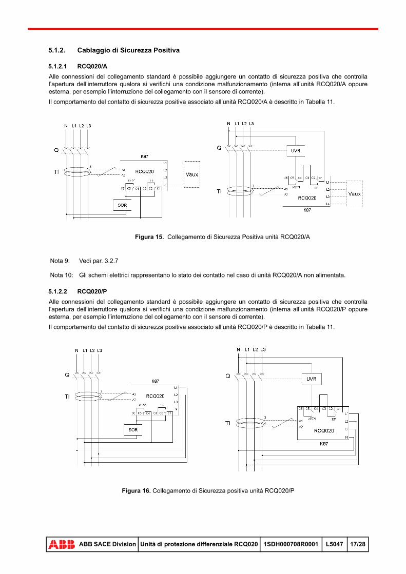
5.1.2. Positive Safety wiring
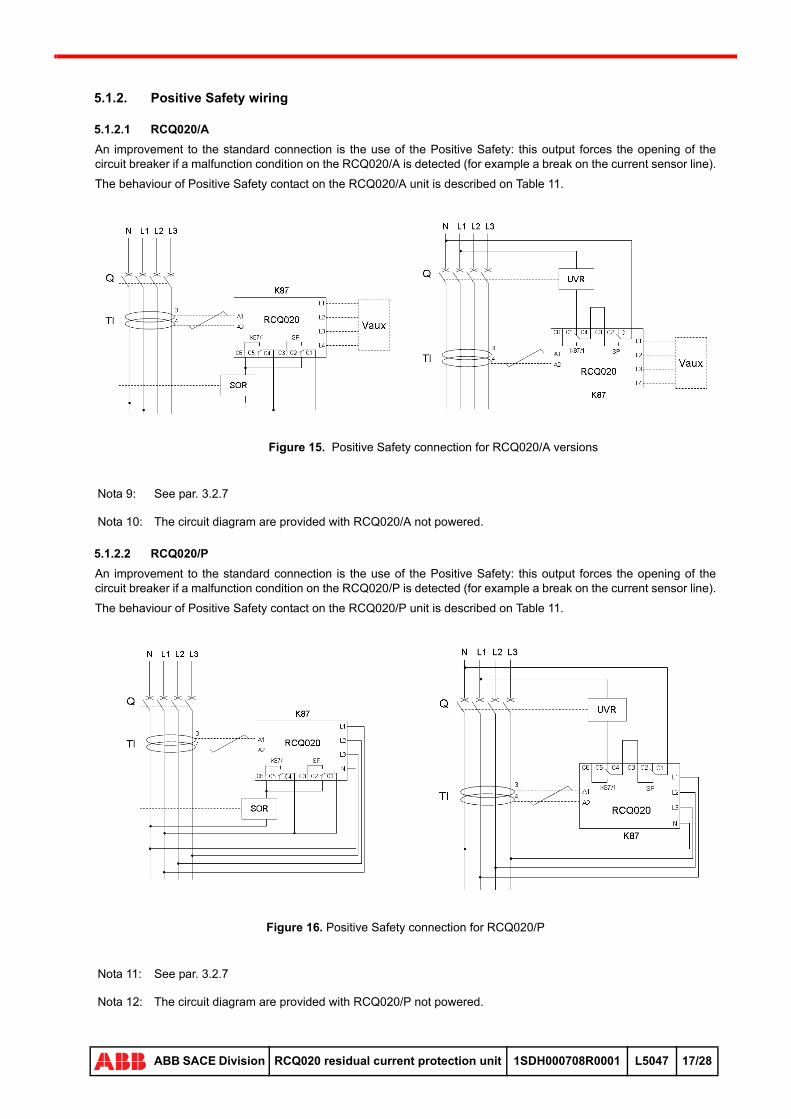
5.1.2.1 RCQ020/A
An improvement to the standard connection is the use of the Positive Safety: this output forces the opening of the circuit breaker if a malfunction condition on the RCQ020/A is detected (for example a break on the current sensor line).
The behaviour of Positive Safety contact on the RCQ020/A unit is described on Table 11.
Figure 15. Positive Safety connection for RCQ020/A versions
5.1.2.2 RCQ020/P
An improvement to the standard connection is the use of the Positive Safety: this output forces the opening of the circuit breaker if a malfunction condition on the RCQ020/P is detected (for example a break on the current sensor line).
The behaviour of Positive Safety contact on the RCQ020/P unit is described on Table 11.
Figure 16. Positive Safety connection for RCQ020/P
Nota 9: See par. 3.2.7
Nota 10: The circuit diagram are provided with RCQ020/A not powered.
Nota 11: See par. 3.2.7
Nota 12: The circuit diagram are provided with RCQ020/P not powered.
28
ABB SACE Division RCQ020 residual current protection unit 1SDH000708R0001 L5047 17/28
5.1.3. Selectivity
5.1.3.1 Amperometric and chronometric selectivity
The selectivity function between different RCQ020 units requires a proper use of:
• amperometric selection
• non operating time (chronometric selection) and total break time (residual cureent protection unit delay plus actuator switching time), see Figure 17 and Figure 18
The following general rules must be considered to assure the selectivity of the network:
• the amperometric selection for the upstream circuit breaker must be 1.4 times greater than the one of the downstream circuit breaker
• the chronometric selection of the upstream circuit breaker must be greater than the total breaking time of the downstream one
5.1.3.2 Zone selectivity
The zone selectivity differs form the standard selectivity because it allows to set the same non operating time on both upstream and downstream circuit breakers.
Connecting the Prealarm / Alarm output of the downstream RCQ020 with the Trip Delay input of the upstream one, the non operating time of the latter is delayed by a fixed time of 150ms.
In this way, it is possible to optimize the operative time within the network.
Note 13: To perform the zone selectivity, put the RL2 dip switch in Alarm position (see Figure 2 and Figure 3).
Note 14: Up to 20 outputs can be connected to each Trip Delay input.
Note 15: The maximum available distance between the upstream and the downstream devices is 250 m.
Note 16: This function doesn’t work with a non operating time of t=0.
28
ABB SACE Division RCQ020 residual current protection unit 1SDH000708R0001 L5047 18/28

6 TECHNICAL SPECIFICATIONS
6.1. Electrical charcteristics
6.1.1. Overall data
6.1.1.1 RCQ020/A
Table 12. General electrical characteristics RCQ020/A
6.1.1.2 RCQ020/P
Table 13. General electrical characteristic RCQ020/P
6.1.2. Power supply
6.1.2.1 RCQ020/A
RCQ020/A unit can be powered by one of the following auxiliary supply:
Table 14. RCQ020/A supply
6.1.2.2 RCQ020/P
RCQ020/P unit can be powered with the following range of three-phase plus neutral system supply:
Table 15. RCQ020/P supply range
RCQ020/P unit is able to operate also if it’s supplied with a three-phase, singlephase with or without neutral systems.
Characteristic Value
Inrush current @ 115Vac 500mA for 50ms
Inrush current @ 230Vac 150mA for 50ms
Inrush current @ 415Vac 100mA for 50ms
Rated power max 2W
Characteristic Value
Inrush current @ 110Vac 300mA for 5ms
Inrush current @ 690Vac 2A for 5ms
Rated power @ 115Vac single phase max 3W
Rated power @ 230Vac single phase max 3W
Rated power @ 600Vac single phase max 4W
Rated voltage (Ue) Ue range Frequency Frequency range115Vac
-20% ... +10% 50/60Hz ± 10%230Vac
415Vac
Tensione nominale (Ue) Frequenza Tolleranza frequenza110 - 690 Vac 50/60Hz ± 10%
28
ABB SACE Division RCQ020 residual current protection unit 1SDH000708R0001 L5047 19/28
6.1.3. Output relays performances
The outputs of the RCQ020, whose mean has already been described in par 3.2.6, consist of monostable electro-mechanical relays; the main features of these relays are pointed out in Table 16.
Table 16. RCQ020 outputs performances
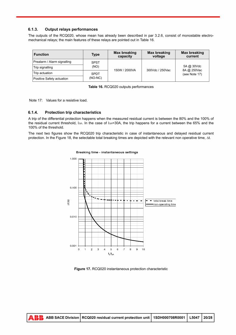
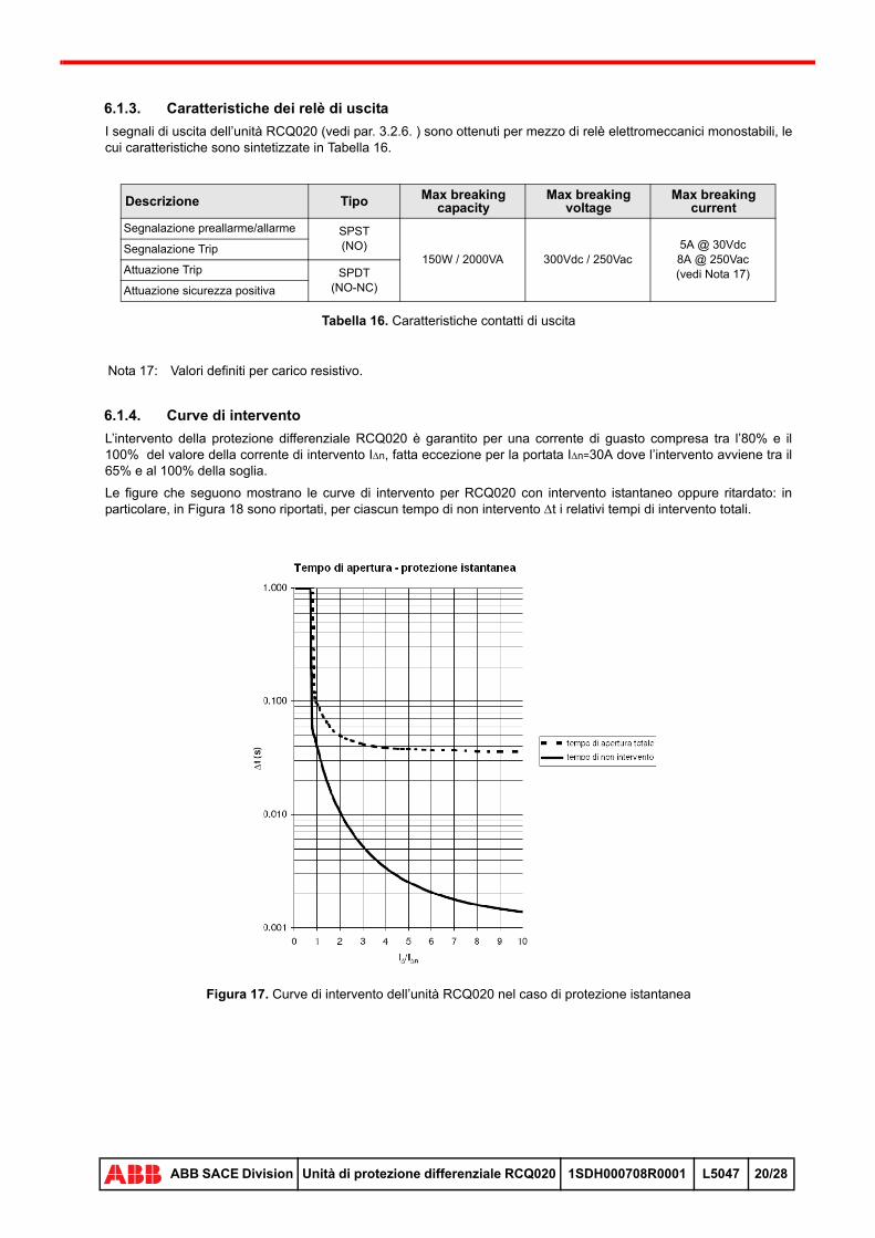
6.1.4. Protection trip characteristics
A trip of the differential protection happens when the measured residual current is between the 80% and the 100% of the residual current threshold, In. In the case of In=30A, the trip happens for a current between the 65% and the 100% of the threshold.
The next two figures show the RCQ020 trip characteristic in case of instantaneous and delayed residual current protection. In the Figure 18, the selectable total breaking times are depicted with the relevant non operative time, t.
Figure 17. RCQ020 instantaneous protection characteristic
Function Type Max breaking capacity
Max breaking voltage
Max breaking current
Prealarm / Alarm signalling SPST(NO)
150W / 2000VA 300Vdc / 250Vac5A @ 30Vdc8A @ 250Vac(see Note 17)
Trip signalling
Trip actuation SPDT(NO-NC)Positive Safety actuation
Note 17: Values for a resistive load.
28
ABB SACE Division RCQ020 residual current protection unit 1SDH000708R0001 L5047 20/28
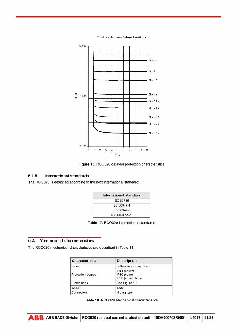
Figure 18. RCQ020 delayed protection characteristics
6.1.5. International standards
The RCQ020 is designed according to the next international standard:
Table 17. RCQ020 international standards
6.2. Mechanical characteristics
The RCQ020 mechanical characteristics are described in Table 18.
Table 18. RCQ020 Mechanical characteristics
International standars
IEC 60755
IEC 60947-1
IEC 60947-2
IEC 60947-5-1
Characteristic Description
Case Self-extinguishing resin
Protection degreeIP41 (cover)IP30 (case)IP20 (connectors)
Dimensions See Figure 19
Weight 420g
Connectors N plug type
28
ABB SACE Division RCQ020 residual current protection unit 1SDH000708R0001 L5047 21/28

Figure 19. RCQ020 dimensions (all the values are in mm)
6.3. Environment conditions
Table 19. Environment conditions
Characteristic Range
Operative temperature -25°C ... +70°C
Storage temperature -40°C ... +90°C
Relative humidity 5% ... 98% with condensation
Altitude 0m ... 2000m
WARNING: Perform the RCQ020 trip test once a month in order to verify the effectiveness of the protection chain.
28
ABB SACE Division RCQ020 residual current protection unit 1SDH000708R0001 L5047 22/28
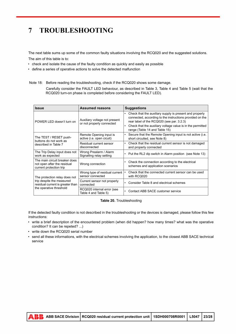
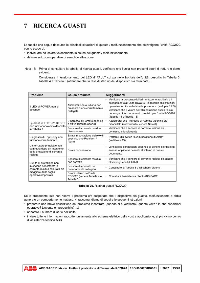
7 TROUBLESHOOTING
The next table sums up some of the common faulty situations involving the RCQ020 and the suggested solutions.
The aim of this table is to:
• check and isolate the cause of the faulty condition as quickly and easily as possible
• define a series of operative actions to solve the detected malfunction
Table 20. Troubleshooting
If the detected faulty condition is not described in the troubleshooting or the devices is damaged, please follow this few instructions:
• write a brief description of the encountered problem (when did happen? how many times? what was the operative condition? It can be repeted? ...)
• write down the RCQ020 serial number
• send all these informations, with the electrical schemes involving the application, to the closest ABB SACE technical service
Note 18: Before reading the troubleshooting, check if the RCQ020 shows some damage.
Carefully consider the FAULT LED behaviour, as described in Table 3, Table 4 and Table 5 (wait that the RCQ020 turn-on phase is completed before considering the FAULT LED).
Issue Assumed reasons Suggestions
POWER LED doesn’t turn onAuxiliary voltage not present or not properly connected
• Check that the auxiliary supply is present and properly connected, according to the instructions provided on the rear label of the RCQ020 (see par. 3.2.3)
• Check that the auxiliary voltage value is in the permitted range (Table 14 and Table 15)
The TEST / RESET push-buttons do not work as described in Table 7
Remote Opening input is active (i.e. open cicuit)
• Secure that the Remote Opening input is not active (i.e. short circuited, see Note 8)
Residual current sensor disconnected
• Check that the residual current sensor is not damaged and properly connected
The Trip Delay input does not work as expected
Wrong Prealarm / Alarm Signalling relay setting
• Put the RL2 dip switch in Alarm position (see Note 13)
The main circuit breaker does not open after the residual current protection trip
Wrong connection• Check the connection according to the electrical
schemes and application scenarios
The protection relay does not trip despite the measured residual current is greater than the operative threshold
Wrong type of residual current sensor connected
• Check that the connected current sensor can be used with RCQ020
Current sensor not properly connected
• Consider Table 8 and electrical schemes
RCQ020 internal error (see Table 4 and Table 5)
• Contact ABB SACE customer service
28
ABB SACE Division RCQ020 residual current protection unit 1SDH000708R0001 L5047 23/28

8 ELECTRICAL SCHEMES
All the electrical schemes are depicted with the following assumptions:
• no power supply is applied to the electrical circuits
• the differential protection is in the normal operative condition (no trip nor alarm /prealarm)
A detailed description of the connections can be found in Table 10.
Figure 20. RCQ020/A connections with SOR type actuators
Figure 21. RCQ020/P connections with SOR type actuators
28
ABB SACE Division RCQ020 residual current protection unit 1SDH000708R0001 L5047 24/28

Figure 22. RCQ020/A connections with UVR type actuators
Figure 23. RCQ020/P connections with UVR type actuators
28
ABB SACE Division RCQ020 residual current protection unit 1SDH000708R0001 L5047 25/28

Figure 24. RCQ020/A 115Vac power supply connection
Figure 25. RCQ020/A 230Vac power supply connection
28
ABB SACE Division RCQ020 residual current protection unit 1SDH000708R0001 L5047 26/28
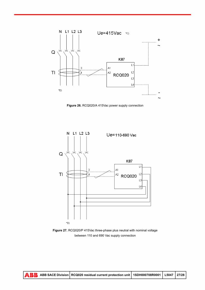
Figure 26. RCQ020/A 415Vac power supply connection
Figure 27. RCQ020/P 415Vac three-phase plus neutral with nominal voltage
between 110 and 690 Vac supply connection
28
ABB SACE Division RCQ020 residual current protection unit 1SDH000708R0001 L5047 27/28
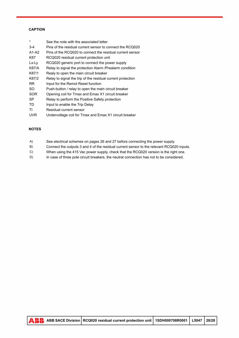
CAPTION
NOTES
* See the note with the associated letter
3-4 Pins of the residual current sensor to connect the RCQ020
A1-A2 Pins of the RCQ020 to connect the residual current sensor
K87 RCQ020 residual current protection unit
Lx-Ly RCQ020 generic port to connect the power supply
K87/A Relay to signal the protection Alarm /Prealarm condition
K87/1 Realy to open the main circuit breaker
K87/2 Relay to signal the trip of the residual current protection
RR Input for the Remot Reset function
SO Push-button / relay to open the main circuit breaker
SOR Opening coil for Tmax and Emax X1 circuit breaker
SP Relay to perform the Positive Safety protection
TD Input to enable the Trip Delay
TI Residual current sensor
UVR Undervoltage coil for Tmax and Emax X1 circuit breaker
A) See electrical schemes on pages 26 and 27 before connecting the power supply.B) Connect the outputs 3 and 4 of the residual current sensor to the relevant RCQ020 inputs.C) When using the 415 Vac power supply, check that the RCQ020 version is the right one.D) In case of three pole circuit breakers, the neutral connection has not to be considered.
28
ABB SACE Division RCQ020 residual current protection unit 1SDH000708R0001 L5047 28/28

2
ABB SACE Division Unità di protezione differenziale RCQ020 1SDH000708R0001 L5047 IT
UNITA’ DI PROTEZIONE DIFFERENZIALE RCQ020/A e RCQ020/P

INDICE
1. NOTE SULLA SICUREZZA ................................................................................................................................. 21.1. Note per prove di rigidità dielettrica .................................................................................................. 2
2. INTRODUZIONE ................................................................................................................................................... 32.1. Descrizione generale ........................................................................................................................ 3
2.1.1. Principio di funzionamento ...................................................................................................... 32.1.2. Versioni disponibili .................................................................................................................. 3
2.2. Riferimenti ......................................................................................................................................... 4
3. INTERFACCIA UTENTE ..................................................................................................................................... 53.1. Vista frontale ..................................................................................................................................... 5
3.1.1. RCQ020/A .............................................................................................................................. 53.1.2. RCQ020/P .............................................................................................................................. 63.1.3. Selettore Amperometrico ........................................................................................................ 63.1.4. Selettore Cronometrico ........................................................................................................... 63.1.5. LED di segnalazione ............................................................................................................... 7
3.1.5.1. LED di FAULT ........................................................................................................... 73.1.5.1.1. RCQ020/A .................................................................................................... 73.1.5.1.2. RCQ020/P .................................................................................................... 7
3.1.6. Dip-switch ............................................................................................................................... 83.1.7. Pulsanti ................................................................................................................................... 83.1.8. Connettore di Test .................................................................................................................. 83.1.9. Barra LED ............................................................................................................................... 9
3.2. Vista posteriore ................................................................................................................................. 93.2.1. RCQ020/A .............................................................................................................................. 93.2.2. RCQ020/P ............................................................................................................................ 103.2.3. Alimentazione ....................................................................................................................... 10
3.2.3.1. RCQ020/A ............................................................................................................... 103.2.3.2. RCQ020/P ............................................................................................................... 11
3.2.4. Sensore di guasto a terra ..................................................................................................... 123.2.5. Dispositivi di apertura ........................................................................................................... 133.2.6. Ingressi e uscite .................................................................................................................... 143.2.7. Sicurezza Positiva ................................................................................................................ 14
4. INSTALLAZIONE E MESSA IN SERVIZIO ..................................................................................................... 54.1. Istruzioni per l’installazione ............................................................................................................. 15
5. SCENARI APPLICATIVI .................................................................................................................................... 165.1. Connessioni unità RCQ020 ............................................................................................................ 16
5.1.1. Collegamento standard ......................................................................................................... 165.1.1.1. RCQ020/A ............................................................................................................... 165.1.1.2. RCQ020/P ............................................................................................................... 16
5.1.2. Cablaggio di Sicurezza Positiva ........................................................................................... 175.1.2.1. RCQ020/A ............................................................................................................... 175.1.2.2. RCQ020/P ............................................................................................................... 17
5.1.3. Selettività .............................................................................................................................. 185.1.3.1. Selettività amperometrica e cronometrica ............................................................... 185.1.3.2. Selettività di Zona .................................................................................................... 18
6. SPECIFICHE TECNICHE .................................................................................................................................. 196.1. Caratteristiche elettriche ................................................................................................................. 19
6.1.1. Dati generali .......................................................................................................................... 196.1.1.1. RCQ020/A ............................................................................................................... 196.1.1.2. RCQ020/P ............................................................................................................... 19
6.1.2. Alimentazione ....................................................................................................................... 196.1.2.1. RCQ020/A ............................................................................................................... 196.1.2.2. RCQ020/P ............................................................................................................... 19
1
ABB SACE Division Unità di protezione differenziale RCQ020 1SDH000708R0001 L5047 IT
6.1.3. Caratteristiche dei relè di uscita ............................................................................................ 206.1.4. Curve di intervento ................................................................................................................ 206.1.5. Standard internazionali di riferimento ................................................................................... 21
6.2. Caratteristiche meccaniche ............................................................................................................. 216.3. Condizioni ambientali ...................................................................................................................... 22
7. RICERCA GUASTI .............................................................................................................................................. 23
8. SCHEMI ELETTRICI .......................................................................................................................................... 24
1
ABB SACE Division Unità di protezione differenziale RCQ020 1SDH000708R0001 L5047 IT
1 NOTE SULLA SICUREZZA
Leggere attentamente e completamente il presente manuale prima dell’installazione e messa in servizio dell’unità RCQ020.
L’utilizzo del dispositivo dovrebbe essere riservato esclusivamente a personale qualificato e competente.
In caso di dubbi sull’utilizzo in sicurezza, l’unità deve essere messa fuori servizio e garantita contro un uso non intenzionale.
Si deve supporre che non sia possibile un uso sicuro se:
1. l’unità presenta danni visibili2. l’unità non funziona (ad esempio con l’autotest o mediante unità di test)3. l’unità ha subito danni durante il trasporto
Prima di effettuare qualsiasi azione e/o sostituzione, accertarsi di aver messo in sicurezza l’area di intervento, per esempio rimuovendo tutte le alimentazioni connesse ed eventuali altre tensioni pericolose.
1.1. Note per prove di rigidità dielettrica
ATTENZIONE: Questo simbolo identifica informazioni riguardanti pratiche, azioni o circostanze che possono scaturire in ferite o lesioni del personale, danni all’unità o perdite economiche.
ATTENZIONE: Non sono ammesse prove di rigidità dielettrica sugli ingressi e sulle uscite del dispositivo.In caso di prove dielettriche sul quadro, disconnettere tutti i cablaggi relativi ai morsetti dell’unità RCQ020.
28
ABB SACE Division Unità di protezione differenziale RCQ020 1SDH000708R0001 L5047 2/28

2 INTRODUZIONE
2.1. Descrizione generale
L’unità RCQ020 è un relè differenziale da quadro, abbinabile ad interruttori di bassa tensione della serie Tmax (da T1 a T7), Emax X1 e XTmax; pertanto, implementa la funzione di protezione da guasto a terra.
In generale, il sistema deve prevedere:
• una sorgente di alimentazione
• un sensore di guasto a terra (tipicamente un trasformatore toroidale)
• attuatori elettromeccanici per l’apertura dell’interruttore, ad esempio bobine di apertura (SOR) o di minima tensione (UVR)
L’unità RCQ020 è inoltre provvista di ingressi per comandare l’apertura da remoto oppure implemetare la funzione di sicurezza positiva che, in caso di malfunzionamento o guasto, garantisce la messa in sicurezza dell’impianto.
La Figura 1 schematizza sinteticamente il sistema fin qui descritto.
Figura 1. Schema a blocchi del sistema
2.1.1. Principio di funzionamento
Il sensore di guasto a terra è attraversato dai conduttori di linea: la somma vettoriale delle correnti circolanti sui conduttori è normalmente nulla; in presenza di una dispersione verso terra di uno o più conduttori, si ha uno sbilanciamento della somma, pari all’entità del guasto a terra.
Tale sbilanciamento è letto dall’unità RCQ020 e confrontato con la soglia di corrente operativa In: in caso venga rilevata una corrente residua superiore all’80% della soglia impostata per un tempo minimo pari al tempo di non intervento t, RCQ020 attiva l’intervento dell’attuatore elettromeccanico per comandare l’apertura dell’interruttore.
La condizione di intervento permane fino a che l’unità non viene resettata, tranne il caso in cui il dip-switch RESET si trovi nella posizione AUTO (vedi Figura 2 e Figura 3).
2.1.2. Versioni disponibili
La gamma delle unità di protezione RCQ020 comprende differenti versioni.
La versione denominata RCQ020/A prevede l’impiego di una sorgente di alimentazione ausiliaria in AC
(vedi par. 3.2.3.1).
La versione denominata RCQ020/P viene alimentata tramite un sistema trifase con neutro
(vedi par. 3.2.3.2).
D’ora in avanti, qualunque riferimento a RCQ020 va inteso come riferimento comune sia a RCQ020/A che
a RCQ020/P.
28
ABB SACE Division Unità di protezione differenziale RCQ020 1SDH000708R0001 L5047 3/28

2.2. Riferimenti
Il presente manuale descrive come installare, configurare e utilizzare l’unità RCQ020.
Per informazioni relative agli interruttori cui l’unità RCQ020 può essere collegata, consultare la seguente documentazione:
• Catalogo tecnico ABB SACE Tmax (doc. 1SDC210015D0903)
• Catalogo tecnico ABB SACE X1 (doc. 1SDC20009D0902)
• Catalogo tecnico ABB SACE XTmax (doc. 1SDC210033D0901)
28
ABB SACE Division Unità di protezione differenziale RCQ020 1SDH000708R0001 L5047 4/28
3 INTERFACCIA UTENTE
3.1. Vista frontale
3.1.1. RCQ020/A
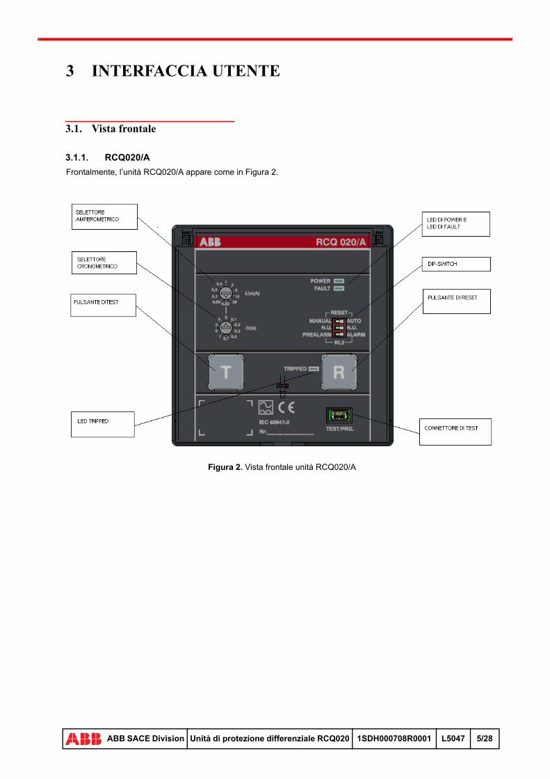
Frontalmente, l’unità RCQ020/A appare come in Figura 2.
Figura 2. Vista frontale unità RCQ020/A
28
ABB SACE Division Unità di protezione differenziale RCQ020 1SDH000708R0001 L5047 5/28
3.1.2. RCQ020/P
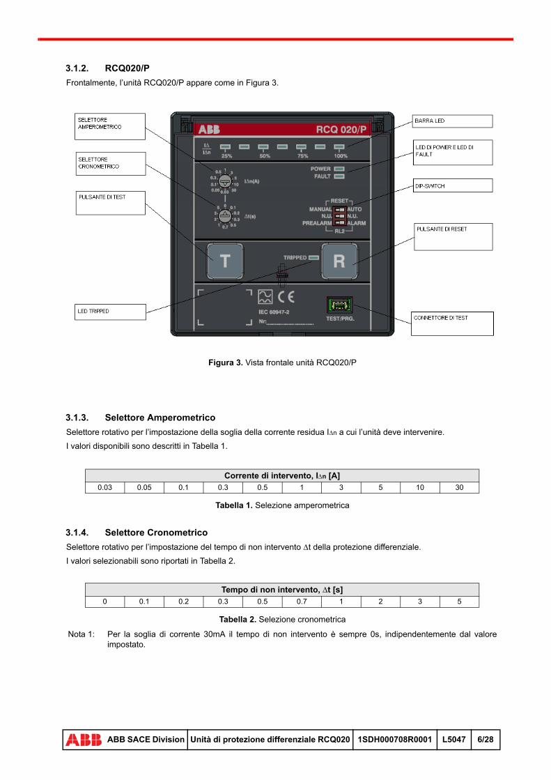
Frontalmente, l’unità RCQ020/P appare come in Figura 3.
Figura 3. Vista frontale unità RCQ020/P
3.1.3. Selettore Amperometrico
Selettore rotativo per l’impostazione della soglia della corrente residua In a cui l’unità deve intervenire.
I valori disponibili sono descritti in Tabella 1.
Tabella 1. Selezione amperometrica
3.1.4. Selettore Cronometrico
Selettore rotativo per l’impostazione del tempo di non intervento t della protezione differenziale.
I valori selezionabili sono riportati in Tabella 2.
Tabella 2. Selezione cronometrica
Corrente di intervento, In [A]0.03 0.05 0.1 0.3 0.5 1 3 5 10 30
Tempo di non intervento, t [s]0 0.1 0.2 0.3 0.5 0.7 1 2 3 5
Nota 1: Per la soglia di corrente 30mA il tempo di non intervento è sempre 0s, indipendentemente dal valore impostato.
28
ABB SACE Division Unità di protezione differenziale RCQ020 1SDH000708R0001 L5047 6/28
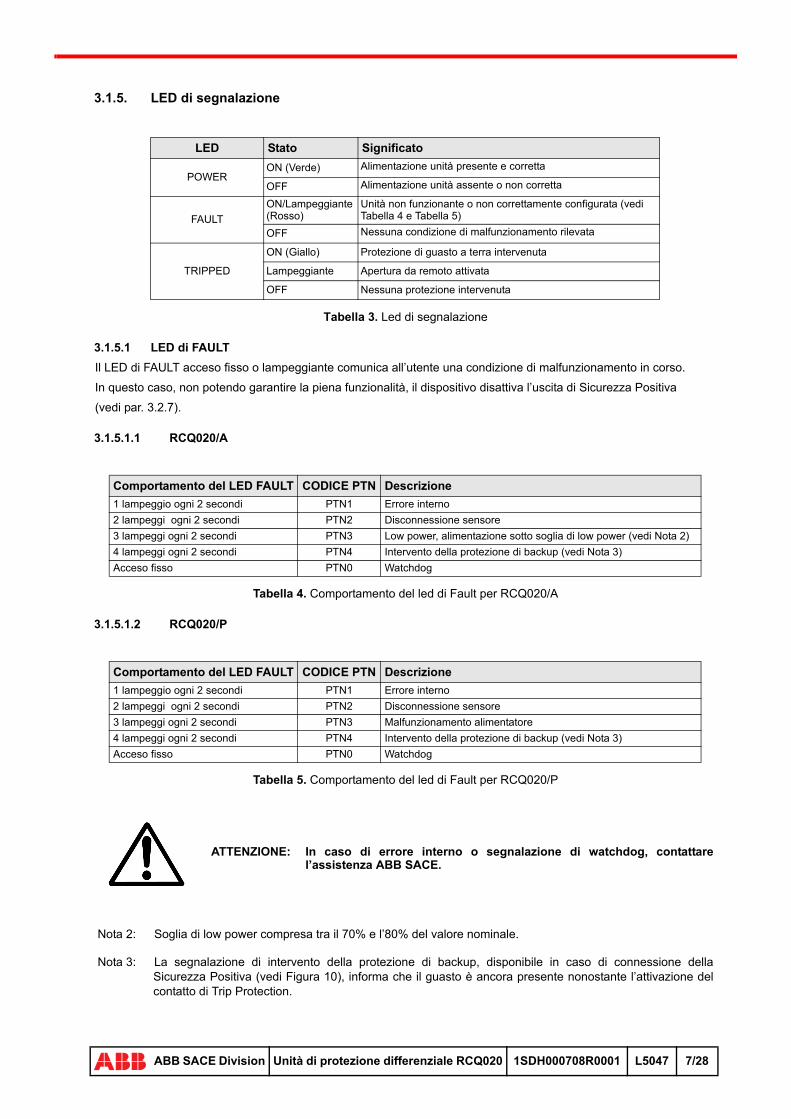
3.1.5. LED di segnalazione
Tabella 3. Led di segnalazione
3.1.5.1 LED di FAULT
Il LED di FAULT acceso fisso o lampeggiante comunica all’utente una condizione di malfunzionamento in corso.
In questo caso, non potendo garantire la piena funzionalità, il dispositivo disattiva l’uscita di Sicurezza Positiva
(vedi par. 3.2.7).
3.1.5.1.1 RCQ020/A
Tabella 4. Comportamento del led di Fault per RCQ020/A
3.1.5.1.2 RCQ020/P
Tabella 5. Comportamento del led di Fault per RCQ020/P
LED Stato Significato
POWERON (Verde) Alimentazione unità presente e corretta
OFF Alimentazione unità assente o non corretta
FAULT
ON/Lampeggiante (Rosso)
Unità non funzionante o non correttamente configurata (vedi Tabella 4 e Tabella 5)
OFF Nessuna condizione di malfunzionamento rilevata
TRIPPED
ON (Giallo) Protezione di guasto a terra intervenuta
Lampeggiante Apertura da remoto attivata
OFF Nessuna protezione intervenuta
Comportamento del LED FAULT CODICE PTN Descrizione
1 lampeggio ogni 2 secondi PTN1 Errore interno
2 lampeggi ogni 2 secondi PTN2 Disconnessione sensore
3 lampeggi ogni 2 secondi PTN3 Low power, alimentazione sotto soglia di low power (vedi Nota 2)
4 lampeggi ogni 2 secondi PTN4 Intervento della protezione di backup (vedi Nota 3)
Acceso fisso PTN0 Watchdog
Comportamento del LED FAULT CODICE PTN Descrizione
1 lampeggio ogni 2 secondi PTN1 Errore interno
2 lampeggi ogni 2 secondi PTN2 Disconnessione sensore
3 lampeggi ogni 2 secondi PTN3 Malfunzionamento alimentatore
4 lampeggi ogni 2 secondi PTN4 Intervento della protezione di backup (vedi Nota 3)
Acceso fisso PTN0 Watchdog
ATTENZIONE: In caso di errore interno o segnalazione di watchdog, contattare l’assistenza ABB SACE.
Nota 2: Soglia di low power compresa tra il 70% e l’80% del valore nominale.
Nota 3: La segnalazione di intervento della protezione di backup, disponibile in caso di connessione della Sicurezza Positiva (vedi Figura 10), informa che il guasto è ancora presente nonostante l’attivazione del contatto di Trip Protection.
28
ABB SACE Division Unità di protezione differenziale RCQ020 1SDH000708R0001 L5047 7/28
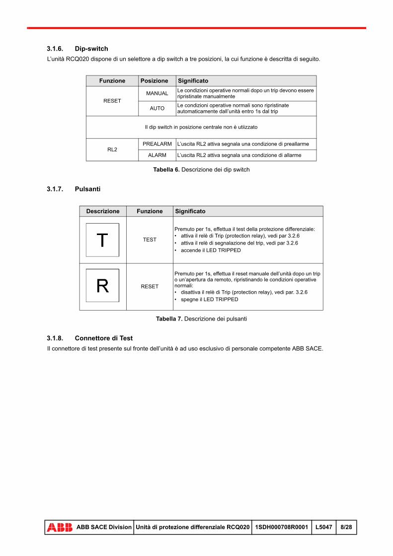
3.1.6. Dip-switch
L’unità RCQ020 dispone di un selettore a dip switch a tre posizioni, la cui funzione è descritta di seguito.
Tabella 6. Descrizione dei dip switch
3.1.7. Pulsanti
Tabella 7. Descrizione dei pulsanti
3.1.8. Connettore di Test
Il connettore di test presente sul fronte dell’unità è ad uso esclusivo di personale competente ABB SACE.
Funzione Posizione Significato
RESET
MANUALLe condizioni operative normali dopo un trip devono essere ripristinate manualmente
AUTOLe condizioni operative normali sono ripristinate automaticamente dall’unità entro 1s dal trip
Il dip switch in posizione centrale non è utiizzato
RL2PREALARM L’uscita RL2 attiva segnala una condizione di preallarme
ALARM L’uscita RL2 attiva segnala una condizione di allarme
Descrizione Funzione Significato
TEST
Premuto per 1s, effettua il test della protezione differenziale:• attiva il relè di Trip (protection relay), vedi par 3.2.6• attiva il relè di segnalazione del trip, vedi par 3.2.6• accende il LED TRIPPED
RESET
Premuto per 1s, effettua il reset manuale dell’unità dopo un trip o un’apertura da remoto, ripristinando le condizioni operative normali:• disattiva il relè di Trip (protection relay), vedi par. 3.2.6• spegne il LED TRIPPED
28
ABB SACE Division Unità di protezione differenziale RCQ020 1SDH000708R0001 L5047 8/28
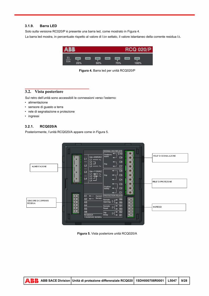
3.1.9. Barra LED
Solo sulla versione RC020/P è presente una barra led, come mostrato in Figura 4.
La barra led mostra, in percentuale rispetto al valore di In settato, il valore istantaneo della corrente residua I.
Figura 4. Barra led per unità RCQ020/P
3.2. Vista posteriore
Sul retro dell’unità sono accessibili le connessioni verso l’esterno:
• alimentazione
• sensore di guasto a terra
• rele di segnalazione e protezione
• ingressi
3.2.1. RCQ020/A
Posteriormente, l’unità RCQ020/A appare come in Figura 5.
Figura 5. Vista posteriore unità RCQ020/A
28
ABB SACE Division Unità di protezione differenziale RCQ020 1SDH000708R0001 L5047 9/28

3.2.2. RCQ020/P
Posteriormente, l’unità RCQ020/P appare come in Figura 6.
Figura 6. Vista posteriore unità RCQ020/P
3.2.3. Alimentazione
3.2.3.1 RCQ020/A
L’unità RCQ020/A deve essere alimentata con una tensione ausiliaria alternata, eventualmente derivata dalla tensione di linea dell’impianto monitorato (vedi Nota 4).
Dipendentemente dal valore di alimentazione AC, sono disponibili due differenti versioni dell’unità RCQ020/A:
• la prima, indicata come ‘A’ in Figura 7, funziona a 115Vac oppure a 230Vac (vedi Nota 5)
• la seconda, indicata come ‘B’ in Figura 7, opera a 415Vac (vedi Nota 5)
Effettuare le connessioni dell’alimentazione come riportato negli schemi elettrici al capitolo 8 .
Nota 4: Se la tensione ausiliaria è derivata dalla stessa linea di alimentazione che si sta monitorando, è necessario realizzare la connessione di sicurezza positiva, come descritto nel par. 5.1.2
Nota 5: Collegare l’alimentazione nel modo corrispondente all’alimentazione selezionata, come da etichetta sul lato posteriore dell’unità e riportata in Figura 7.
28
ABB SACE Division Unità di protezione differenziale RCQ020 1SDH000708R0001 L5047 10/28
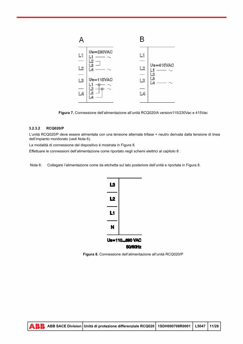
Figura 7. Connessione dell’alimentazione all’unità RCQ020/A versioni115/230Vac e 415Vac
3.2.3.2 RCQ020/P
L’unità RCQ020/P deve essere alimentata con una tensione alternata trifase + neutro derivata dalla tensione di linea dell’impianto monitorato (vedi Nota 6).
La modalità di connessione del dispositivo è mostrata in Figura 8.
Effettuare le connessioni dell’alimentazione come riportato negli schemi elettrici al capitolo 8 .
Figura 8. Connessione dell’alimentazione all’unità RCQ020/P
Nota 6: Collegare l’alimentazione come da etichetta sul lato posteriore dell’unità e riportata in Figura 8.
28
ABB SACE Division Unità di protezione differenziale RCQ020 1SDH000708R0001 L5047 11/28

3.2.4. Sensore di guasto a terra
Il sensore di guasto a terra consente di rilevare lo sbilanciamento delle correnti circolanti nei conduttori attivi di linea.
Il sensore è un trasformatore toroidale di tipo chiuso, disponibile in diversi diametri a seconda della sensibilità richiesta dall’applicazione.
Di seguito sono elencati i trasformatori abbinabili all’unità RCQ020.
Tabella 8. RCQ020 e sensori toroidali di corrente residua
I morsetti 1-2 del sensore di corrente residua devono essere lasciati scollegati.
Prestare attenzione al posizionamento dei cavi all’interno del toroide: questi ultimi devono essere disposti al centro del toroide, come illustrato nella figura che segue.
Figura 9. Disposizione e fissaggio dei cavi all’interno del toroide
Figura 10. Dimensioni toroidi per RCQ020
TipoCorrentenominalemax, In
Sogliadi interventominima, In
Un Uimp Icw IwMorsetti di collegamento
RCQ020 Sensore di corrente residua
Chiuso 60mm
250A 30mA
1000Vac 8KVac42KAper1s
42KAper
0,5 s
20KAper1 s
A1-A2(vedi Figura 5
e Figura 6)3-4
Chiuso 110mm
400A 30mA
Chiuso 185mm
800A 100mA
28
ABB SACE Division Unità di protezione differenziale RCQ020 1SDH000708R0001 L5047 12/28

E’ opportuno installare il sensore il più vicino possibile al relè; in ogni caso è consigliata l’installazione ad una distanza massima di 15m.
Per installare un toroide, procedere secondo le indicazioni di Fig. 11.
Figura 11. Montaggio tori RCQ020
Montare il trasformatore toroidale (3) sulle connessioni di alimentazione dell’impianto. Fissare il toroide al supporto (5, 6, 7, 8). Infine collegare il trasformatore al relè differenziale.
Accertarsi che il cavo di misura sia collocato a distanza rispetto al cavo di alimantazione e, in generale, ai conduttori di potenza o altre apparecchiature che possano indurre disturbi.
Utilizzare un cavo bifilare schermato con conduttori intrecciati (tipo BELDEN 3105A). Lo schermo va messo a terra lato unità RCQ020.
La resistenza del cavo deve essere inferiore a 3.
3.2.5. Dispositivi di apertura
In Tabella 9 vengono descritti i dispositivi di apertura abbinabili all’unità RCQ020.
Tabella 9. Dispositivi di apertura abbinabili all’unità RCQ020
CB RITARDO CON SOR RITARDO CON UVRT1 Istantaneo Istantaneo
T2 Istantaneo Istantaneo
T3 Istantaneo Istantaneo
T4 Istantaneo Istantaneo
T5 Istantaneo Istantaneo
T6 Istantaneo Istantaneo
T7 Istantaneo 100ms
X1 Istantaneo 100ms
XT1 Istantaneo Istantaneo
XT2 Istantaneo Istantaneo
XT3 Istantaneo Istantaneo
XT4 Istantaneo Istantaneo
Nota 7: Per applicazioni con tensioni superiori a 250Vac contattare l’assistenza ABB SACE.
28
ABB SACE Division Unità di protezione differenziale RCQ020 1SDH000708R0001 L5047 13/28
3.2.6. Ingressi e uscite
L’unità RCQ020 dispone di ingressi e uscite digitali dedicati alla segnalazione e all’attivazione della protezione differenziale - attuazione bobina di apertura dell’interruttore principale (vedi Tabella 10).
I contatti di uscita dedicati alla segnalazione sono di tipo “singolo polo singolo contatto” (SPST, NO); al contrario, quelli preposti alle funzioni di protezione sono di tipo “singolo polo doppio contatto” (SPDT, NO-NC).
Tabella 10. Ingressi e uscite del relè RCQ020
3.2.7. Sicurezza Positiva
Il collegamento del contatto di Sicurezza Positiva è a cura dell’utente.
In caso di utilizzo del dispositivo RCQ020/A, se la tensione ausiliaria è ricavata dalle linee principali che si stanno monitorando, è necessario realizzare la connessione di sicurezza positiva: in questo modo, in caso di guasto o malfunzionamento sulla linea e conseguente spegnimento dell’unità RCQ020/A, l’interruttore sui principale apre mettendo in condizioni di sicurezza l’impianto.
Vedere anche gli schemi elettrici (vedi par. 5.1.2).
L’uscita è non attiva (contatto C1-C3 chiuso) durante il normale funzionamento dell’unità e si attiva (contatto C1-C2 chiuso) per comandare l’attuazione del dispositivo di apertura dell’interruttore.
Tabella 11. Funzionamento del contatto Sicurezza Positiva
Direzione Funzione Significato Morsetti RCQ020
Ingresso
Remote OpeningComanda l’apertura di emergenza dell’interruttore da remoto, ad esempio mediante pressione di un pulsante esterno (vedi Nota 8).
B5-B6
Remote Reset Comanda il reset remoto dell’unità RCQ020 B3-B4
Trip DelayIntroduce un ritardo fisso pari a 150ms sull’intervento della protezione (Trip protection relay)
B1-B2
Uscita
Prealarm / Alarm
Contatto SPST normalmente aperto.Segnala una condizione di Preallarme / Allarme della protezione differenziale, in accordo alla configurazione del relativo dip switch (vedi Tabella 6)
C9-C10
Trip (Signalling Relay)Contatto SPST normalmente aperto.Segnala l’intervento della protezione differenziale
C7-C8
Trip (Protection Relay)Contatto SPDT, C4-C5 normalmente chiuso.Comanda l’attuazione della trip coil dell’interruttore collegato all’unità RCQ020
C4-C5-C6
Positive Safety
Contatto SPDT, C1-C2 chiuso a relé spento.In caso di malfunzionamento dell’unità differenziale, comanda l’attuazione della trip coil dell’interruttore collegato all’unità RCQ020 (vedi par. 3.2.7).
C1-C2-C3
Nota 8: La condizione di funzionamento normale corrisponde all’ingresso B5-B6 chiuso in corto.
In caso di interruzione del collegamento (contatto B5-B6 aperto), l’unità RCQ020 forza l’apertura dell’interruttore.
L’apertura remota non commuta il relè di segnalazione del trip (contatto C7-C8) mentre attiva il lampeggio del LED TRIPPED; per rirpistinare il funzionamento normale dell’unità è necessario operare localmente un reset, mediante pressione del pulsante corrispondente.
Stato relè Contatto di Sicurezza Positiva Stato SOR / UVR
Funzionamento normaleC1-C2 apertoC1-C3 chiuso
A riposo
MalfunzionamentoC1-C2 chiusoC1-C3 aperto
Scattata
28
ABB SACE Division Unità di protezione differenziale RCQ020 1SDH000708R0001 L5047 14/28
4 INSTALLAZIONE E MESSA IN SERVIZIO
4.1. Istruzioni per l’installazione
Per il montaggio del relè differenziale RCQ020 nel quadro elettrico, seguire le istruzioni descritte di seguito e riportate schematicamente in Figura 12:
• eseguire la foratura della portella della cella in base alla indicazioni riportate in Figura 19
• introdurre il relè nel senso indicato dalla freccia
Figura 12. Installazione RCQ020
Realizzare le connessioni elettriche come descritto nel par. 3.2 e negli schemi elettrici al capitolo 8.
Per ciascun ingresso / uscita non sono consentiti collegamenti differenti da quelli descritti nella documentazione ufficiale ABB.
Se l’unità RCQ020 è installata nel quadro accanto ad altri dispositivi che generano campi elettromagnetici (relè, trasformatori, controllo motori, ecc.), è necessario prevedere un’opportuna schermatura, messa a terra o altri accorgimenti atti a evitare o ridurre effetti indesiderati, quali rumore elettrico indotto sulle linee di segnale o di potenza.
28
ABB SACE Division Unità di protezione differenziale RCQ020 1SDH000708R0001 L5047 15/28

5 SCENARI APPLICATIVI
5.1. Connessioni unità RCQ020
Questa sezione del manuale è dedicata alla descrizione degli scenari applicativi previsti per l’unità RCQ020, con particolare riferimento alle possibili connessioni con gli interruttori della serie Tmax, Emax X1 e XTmax.
5.1.1. Collegamento standard
5.1.1.1 RCQ020/A
L’applicazione standard dell’unità RCQ020/A prevede la connessione di:
• sorgente di alimentazione ausiliaria
• sensore di corrente
• attuatore elettromeccanico, tipo SOR oppure UVR, per comandare l’apertura dell’interruttore
Figura 13. Collegamento standard unità RCQ020/A
5.1.1.2 RCQ020/P
L’applicazione standard dell’unità RCQ020/P prevede la connessione di:
• sistema di alimentazione trifase + neutro
• sensore di corrente
• attuatore elettromeccanico, tipo SOR oppure UVR, per comandare l’apertura dell’interruttore
Figura 14. Collegamento standard unità RCQ020/P
28
ABB SACE Division Unità di protezione differenziale RCQ020 1SDH000708R0001 L5047 16/28
5.1.2. Cablaggio di Sicurezza Positiva
5.1.2.1 RCQ020/A
Alle connessioni del collegamento standard è possibile aggiungere un contatto di sicurezza positiva che controlla l’apertura dell’interruttore qualora si verifichi una condizione malfunzionamento (interna all’unità RCQ020/A oppure esterna, per esempio l’interruzione del collegamento con il sensore di corrente).
Il comportamento del contatto di sicurezza positiva associato all’unità RCQ020/A è descritto in Tabella 11.
Figura 15. Collegamento di Sicurezza Positiva unità RCQ020/A
5.1.2.2 RCQ020/P
Alle connessioni del collegamento standard è possibile aggiungere un contatto di sicurezza positiva che controlla l’apertura dell’interruttore qualora si verifichi una condizione malfunzionamento (interna all’unità RCQ020/P oppure esterna, per esempio l’interruzione del collegamento con il sensore di corrente).
Il comportamento del contatto di sicurezza positiva associato all’unità RCQ020/P è descritto in Tabella 11.
Figura 16. Collegamento di Sicurezza positiva unità RCQ020/P
Nota 9: Vedi par. 3.2.7
Nota 10: Gli schemi elettrici rappresentano lo stato dei contatto nel caso di unità RCQ020/A non alimentata.
28
ABB SACE Division Unità di protezione differenziale RCQ020 1SDH000708R0001 L5047 17/28
5.1.3. Selettività
5.1.3.1 Selettività amperometrica e cronometrica
La funzione di selettività tra RCQ020 è ottenuta mediante un’opportuna configurazione di:
• seleziona amperometrica
• selezione cronometrica e tempo totale di apertura (tempo di intervento della protezione di corrente residua più ritardo di commutazione dell’attuatore elettromeccanico), vedi Figura 17 e Figura 18
Per assicurare il corretto funzionamento del sistema, è necessario seguire le seguenti regole generali sulla selettività:
• la selezione amperometrica del relè a monte deve essere 1,4 volte maggiore rispetto a quella del relè a valle
• la selezione cronometrica del relè a monte deve essere maggiore del tempo totale di apertura di quello a valle
5.1.3.2 Selettività di Zona
La selettività di zona differisce da quella descritta in precedenza per il fatto che è possibile selezionare lo stesso tempo di non intervento per il dispositivo a monte e per quello a valle.
Infatti, connettendo l’uscita di Prealarm / Alarm del relè a valle all’ingresso di Trip delay di quello a monte, il tempo di non intervento di quest’ultimo risulta ritardato di 150ms.
In questo modo, la funzione di selettività di zona consente di ottimizzare il tempo di intervento rispetto alla semplice selettività.
Nota 11: Vedi par. 3.2.7
Nota 12: Gli schemi elettrici rappresentano lo stato dei contatto nel caso di unità RCQ020/P non alimentata.
Nota 13: Per utilizzare la funzione di selettività di zona è necessario impostare il dip switch RL2 su Alarm (vedi Figura 2 e Figura 3).
Nota 14: Per ciascun ingresso di trip delay è possibile collegare fino a 20 uscite Prealarm / Alarm.
Nota 15: La lunghezza massima del collegamento tra il dispositivo a monte e quello a valle è di 250m.
Nota 16: Funzione non disponibile per settaggio t=0.
28
ABB SACE Division Unità di protezione differenziale RCQ020 1SDH000708R0001 L5047 18/28

6 SPECIFICHE TECNICHE
6.1. Caratteristiche elettriche
6.1.1. Dati generali
6.1.1.1 RCQ020/A
Tabella 12. Caratteristiche elettriche generali unità RCQ020/A
6.1.1.2 RCQ020/P
Tabella 13. Caratteristiche elettriche generali RCQ020/P
6.1.2. Alimentazione
6.1.2.1 RCQ020/A
L’unità RCQ020/A è in grado di operare correttamente con i seguenti valori di tensione AC di alimentazione ausiliaria:
Tabella 14. Alimentazioni unità RCQ020/A
6.1.2.2 RCQ020/P
L’unità RCQ020/P è in grado di operare correttamente con i seguenti valori di tensione AC di alimentazione trifase + neutro:
Tabella 15. Alimentazioni unità RCQ020/P
L’unità RCQ020/P è in grado di funzionare anche se alimentata con sistemi trifase, monofase con e senza neutro.
Caratteristica Descrizione
Corrente di inrush @ 115Vac 500mA per 50ms
Corrente di inrush @ 230Vac 150mA per 50ms
Corrente di inrush @ 415Vac 100mA per 50ms
Potenza nominale max 2W
Caratteristica Descrizione
Corrente di inrush @ 110Vac 300mA per 5ms
Corrente di inrush @ 690Vac 2A per 5ms
Potenza nominale @ 115Vac monofase max 3W
Potenza nominale @ 230Vac monofase max 3W
Potenza nominale @ 600Vac monofase max 4W
Tensione nominale (Ue) Tolleranza Ue Frequenza Tolleranza frequenza115 Vac
-20% ... +10% 50/60Hz ± 10%230 Vac
415 Vac
Tensione nominale (Ue) Frequenza Tolleranza frequenza110 - 690 Vac 50/60Hz ± 10%
28
ABB SACE Division Unità di protezione differenziale RCQ020 1SDH000708R0001 L5047 19/28
6.1.3. Caratteristiche dei relè di uscita
I segnali di uscita dell’unità RCQ020 (vedi par. 3.2.6. ) sono ottenuti per mezzo di relè elettromeccanici monostabili, le cui caratteristiche sono sintetizzate in Tabella 16.
Tabella 16. Caratteristiche contatti di uscita
6.1.4. Curve di intervento
L’intervento della protezione differenziale RCQ020 è garantito per una corrente di guasto compresa tra l’80% e il 100% del valore della corrente di intervento In, fatta eccezione per la portata In=30A dove l’intervento avviene tra il 65% e al 100% della soglia.
Le figure che seguono mostrano le curve di intervento per RCQ020 con intervento istantaneo oppure ritardato: in particolare, in Figura 18 sono riportati, per ciascun tempo di non intervento t i relativi tempi di intervento totali.
Figura 17. Curve di intervento dell’unità RCQ020 nel caso di protezione istantanea
Descrizione Tipo Max breaking capacity
Max breaking voltage
Max breaking current
Segnalazione preallarme/allarme SPST(NO)
150W / 2000VA 300Vdc / 250Vac5A @ 30Vdc8A @ 250Vac(vedi Nota 17)
Segnalazione Trip
Attuazione Trip SPDT(NO-NC)Attuazione sicurezza positiva
Nota 17: Valori definiti per carico resistivo.
28
ABB SACE Division Unità di protezione differenziale RCQ020 1SDH000708R0001 L5047 20/28
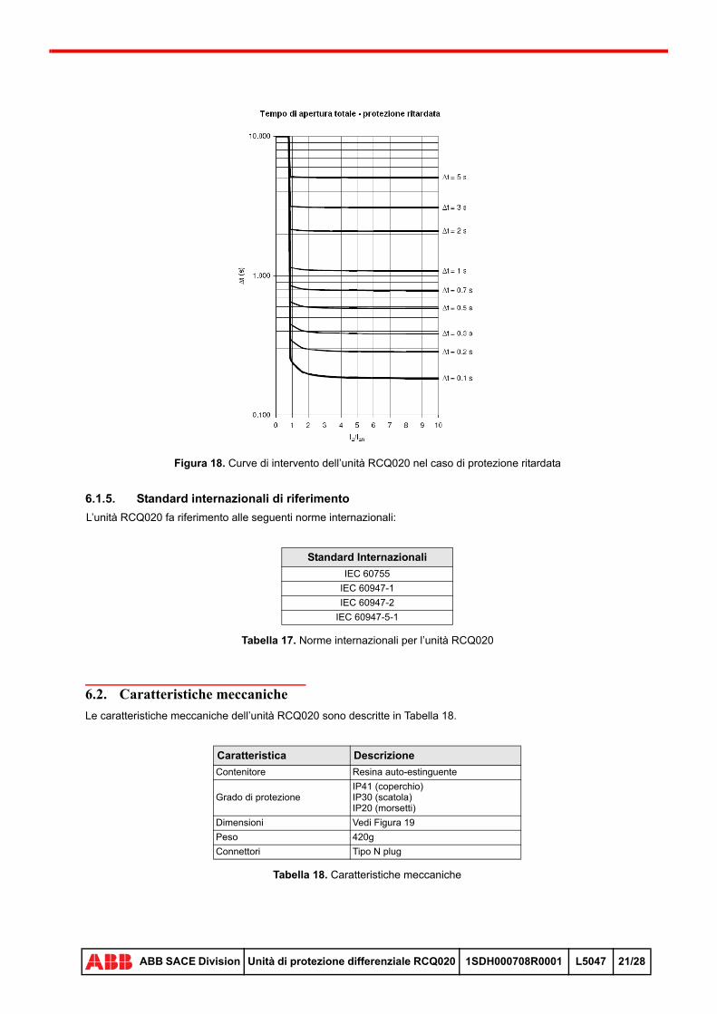
Figura 18. Curve di intervento dell’unità RCQ020 nel caso di protezione ritardata
6.1.5. Standard internazionali di riferimento
L’unità RCQ020 fa riferimento alle seguenti norme internazionali:
Tabella 17. Norme internazionali per l’unità RCQ020
6.2. Caratteristiche meccaniche
Le caratteristiche meccaniche dell’unità RCQ020 sono descritte in Tabella 18.
Tabella 18. Caratteristiche meccaniche
Standard Internazionali
IEC 60755
IEC 60947-1
IEC 60947-2
IEC 60947-5-1
Caratteristica Descrizione
Contenitore Resina auto-estinguente
Grado di protezioneIP41 (coperchio)IP30 (scatola)IP20 (morsetti)
Dimensioni Vedi Figura 19
Peso 420g
Connettori Tipo N plug
28
ABB SACE Division Unità di protezione differenziale RCQ020 1SDH000708R0001 L5047 21/28

Figura 19. Dimensioni dell’unità RCQ020
6.3. Condizioni ambientali
Tabella 19. Condizioni ambientali
Caratteristica Intervallo di applicabilità
Temperatura operativa -25°C ... +70°C
Temperatura di immagazzinamento -40°C ... +90°C
Umidità relativa 5% ... 98% con condensazione
Altitudine 0m ... 2000m
ATTENZIONE: Effettuare un trip test su RCQ020 una volta al mese, per assicurarsi del buono stato di funzionamento della catena di protezione.
28
ABB SACE Division Unità di protezione differenziale RCQ020 1SDH000708R0001 L5047 22/28
7 RICERCA GUASTI
La tabella che segue riassume le principali situazioni di guasto / malfunzionamento che coinvolgono l’unità RCQ020, con lo scopo di:
• individuare ed isolare velocemente la causa del guasto / malfunzionamento
• definire soluzioni operative di semplice attuazione
Tabella 20. Ricerca guasti RCQ020
Se la precedente lista non risolve il problema e/o sospettate che il dispositivo sia guasto, malfunzionante o abbia generato un comportamento inatteso, vi raccomandiamo di seguire le seguenti istruzioni:
• preparare una breve descrizione del problema incontrato (quando si è verificato? quante volte? In che condizioni operative? L’evento è riproducibile? ...)
• annotare il numero di serie dell’unità
• inviare tutte le informazioni raccolte, unitamente allo schema elettrico della vostra applicazione, al più vicino centro di assistenza tecnica ABB
Nota 18: Prima di consultare la tabella di ricerca guasti, verificare che l’unità non presenti segni di rottura o danni evidenti.
Considerare il funzionamento del LED di FAULT sul pannello frontale dell’unità, descritto in Tabella 3, Tabella 4 e Tabella 5 (attendere che la fase di start up del dispositivo sia terminata).
Problema Causa presunta Suggerimenti
Il LED di POWER non si accende
Alimentazione ausiliaria non presente o non correttamente collegata
• Verificare la presenza dell’alimentazione ausiliaria e il collegamento all’unità RCQ020, in accordo alle istruzioni operative fornite sull’etichetta posteriore (vedi par 3.2.3)
• Verificare che il valore dell’alimentazione ausiliaria sia nel range di funzionamento previsto per l’unità RCQ020 (Tabella 14 e Tabella 15)
I pulsanti di TEST e/o RESET non funzionano come descritto in Tabella 7
L’ingresso di Remote opening è attivo (circuito aperto)
• Assicurarsi che l’ingresso di Remote Opening sia disabilitato (cortocircuito, vedere Nota 8)
Sensore di corrente residua disconnesso
• Verificare che il sensore di corrente residua sia connesso e funzionante
L’ingresso di Trip Delay non funziona correttamente
Errata impostazione del relè di segnalazione Prealarm / Alarm
• Portare il dip switch RL2 in posizione di Alarm (vedi Nota 13)
L’interruttore principale non commuta dopo un intervento della protezione di corrente residua
Errata connessione• verificare le connessioni secondo gli schemi elettrici e gli
scenari applicativi descritti all’interno di questo documento
L’unità di protezione non interviene nonostante la corrente residua misurata sia maggiore della soglia operativa impostata
Sensore di corrente residua non corretto
• Verificare che il sensore di corrente residua sia adatto all’impiego con RCQ020
Sensore di corrente non correttamente collegato
• Consultare la Tabella 8 e gli schemi elettrici
Errore interno nell’unità RCQ020 (vedere Tabella 4 e Tabella 5)
• Contattare l’assistenza clienti ABB SACE
28
ABB SACE Division Unità di protezione differenziale RCQ020 1SDH000708R0001 L5047 23/28

8 SCHEMI ELETTRICI
Gli schemi elettrici cono rappresentati nelle seguenti condizioni:
• circuiti in assenza di tensione
• relè differenziale non intervenuto e non in preallarme
Per la descrizione dettagliata dei collegamenti fare riferimento alla Tabella 10.
Figura 20. Collegamento dell’unità RCQ020/A in presenza di attuatori SOR
Figura 21. Collegamento dell’unità RCQ020/P in presenza di attuatori SOR
28
ABB SACE Division Unità di protezione differenziale RCQ020 1SDH000708R0001 L5047 24/28
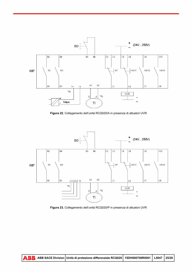
Figura 22. Collegamento dell’unità RCQ020/A in presenza di attuatori UVR
Figura 23. Collegamento dell’unità RCQ020/P in presenza di attuatori UVR
28
ABB SACE Division Unità di protezione differenziale RCQ020 1SDH000708R0001 L5047 25/28

Figura 24. Collegamento dell’alimentazione del dispositivo RCQ020/A per tensione nominale di 115Vac
Figura 25. Collegamento dell’alimentazione del dispositivo RCQ020/A per tensione nominale di 230Vac
28
ABB SACE Division Unità di protezione differenziale RCQ020 1SDH000708R0001 L5047 26/28

Figura 26. Collegamento dell’alimentazione del dispositivo RCQ020/A per tensione nominale di 415Vac
Figura 27. Collegamento del dispositivo RCQ020/P ad un sistema trifase + neutro
con tensione nominale tra 110 e 690 Vac
28
ABB SACE Division Unità di protezione differenziale RCQ020 1SDH000708R0001 L5047 27/28

LEGENDA
NOTE
* Vedere nota indicata dalla lettera
3-4 Morsetti di collegamento al sensore di corrente lato sensore
A1-A2 Morsetti di collegamento al sensore di corrente lato relè
K87 Relè differenziale RCQ020
Lx-Ly Generica porta del relè per il collegamento dell’alimentazione ausiliaria
K87/A Contatto per la segnalazione elettrica di Allarme/Preallarme
K87/1 Contatti di apertura dell’interruttore
K87/2 Contatto per la segnalazione elettrica di relè differenziale intervenuto
RR Contatto per l’abilitazione del Reset Remoto
SO Pulsante o contatto per l’apertura dell’interruttore
SOR Sganciatore di apertura
SP Contatto per l’abilitazione della Sicurezza Positiva
TD Contatto per l’abilitazione del Trip Delay
TI Sensore di corrente
UVR Sganciatore di minima tensione
A) Per la connessione dell’alimentazione fare riferimento agli schemi elettrici alle pagine 26 e 27.B) Collegare le uscite 3 e 4 del sensore di corrente ai corrispondenti ingressi del’unità RCQ020.C) Per il collegamento della tensione nominale 415Vac, è necessario utilizzare la versione corretta di
RCQ020.D) Nel caso di impianti tripolari, non considerare il collegamento del neutro.
28
ABB SACE Division Unità di protezione differenziale RCQ020 1SDH000708R0001 L5047 28/28