resolver input module plot no 43 sector 35, hsiidc operation … · 2014-12-17 · dvp10rc-e2...
TRANSCRIPT
DVP10RC-E2Resolver Input Module Operation Manual
www.deltaww.com2014-11-14
Industrial Automation HeadquartersDelta Electronics, Inc. Taoyuan Technology CenterNo.18, Xinglong Rd., Taoyuan City, Taoyuan County 33068, TaiwanTEL: 886-3-362-6301 / FAX: 886-3-371-6301
AsiaDelta Electronics (Jiangsu) Ltd.Wujiang Plant 31688 Jiangxing East Road, Wujiang Economic Development ZoneWujiang City, Jiang Su Province, P.R.C. 215200TEL: 86-512-6340-3008 / FAX: 86-769-6340-7290
Delta Greentech (China) Co., Ltd.238 Min-Xia Road, Pudong District, ShangHai, P.R.C. 201209TEL: 86-21-58635678 / FAX: 86-21-58630003 Delta Electronics (Japan), Inc.Tokyo Office 2-1-14 Minato-ku Shibadaimon, Tokyo 105-0012, JapanTEL: 81-3-5733-1111 / FAX: 81-3-5733-1211
Delta Electronics (Korea), Inc.1511, Byucksan Digital Valley 6-cha, Gasan-dong, Geumcheon-gu, Seoul, Korea, 153-704TEL: 82-2-515-5303 / FAX: 82-2-515-5302
Delta Electronics Int’l (S) Pte Ltd.4 Kaki Bukit Ave 1, #05-05, Singapore 417939TEL: 65-6747-5155 / FAX: 65-6744-9228
Delta Electronics (India) Pvt. Ltd.Plot No 43 Sector 35, HSIIDC Gurgaon, PIN 122001, Haryana, India TEL : 91-124-4874900 / FAX : 91-124-4874945
AmericasDelta Products Corporation (USA)Raleigh OfficeP.O. Box 12173,5101 Davis Drive, Research Triangle Park, NC 27709, U.S.A.TEL: 1-919-767-3800 / FAX: 1-919-767-8080
Delta Greentech (Brasil) S.A.Sao Paulo OfficeRua Itapeva, 26 - 3° andar Edificio Itapeva One-Bela Vista01332-000-São Paulo-SP-BrazilTEL: 55 11 3568-3855 / FAX: 55 11 3568-3865
EuropeDeltronics (The Netherlands) B.V.Eindhoven OfficeDe Witbogt 20, 5652 AG Eindhoven, The NetherlandsTEL : +31-40-2592850 / FAX : +31-40-2592851
DVP-0001820-01
*We reserve the right to change the information in this manual without prior notice.

i
DVP10RC-E2 Resolver Input Module
Operation Manual
Table of Contents Chapter 1 Introduction
1.1 Specifications ............................................................................1-2
1.2 Dimensions ...............................................................................1-3
1.3 Profile ......................................................................................1-3
1.4 Arrangement of the I/O Terminals ................................................1-4
1.5 Wiring I/O Terminals ..................................................................1-4
1.6 LED Indicators and Troubleshooting..............................................1-4
Chapter 2 Control Registers
2.1 Table of Control Registers ...........................................................2-2
2.2 Functions..................................................................................2-6
2.2.1 Adjusting an Angle ...............................................................2-6
2.2.2 Rotational Speed..................................................................2-7
2.2.3 Counting the Number of Revolutions .......................................2-7
2.2.4 Forward/Backward Rotation ...................................................2-8
2.2.5 Cam Output ........................................................................2-8
2.2.6 Using Y0 and Y1 as High-speed Output Terminals .....................2-9
2.2.7 Controlling a Brake by Means of Y10/Y11 .............................. 2-10
2.2.8 Automatically Bringing out a Gliding Angle List ....................... 2-12
2.2.9 Offset Angle Percentage...................................................... 2-13
2.3 Descriptions of D9900~D9999 ................................................... 2-14

i i

Chapter 1 Introduction Table of Contents 1.1 Specifications ............................................................................1-2 1.2 Dimensions ...............................................................................1-3 1.3 Profile ......................................................................................1-3 1.4 Arrangement of the I/O Terminals ................................................1-4 1.5 Wiring I/O Terminals ..................................................................1-4 1.6 LED Indicators and Troubleshooting ..............................................1-4
1-1
DVP10RC-E2 Resolver Input Module Operat ion Manual
Thanks for using the resolver input module DVP10RC-E2. To ensure that the product is correctly installed and operated, users need to read the operation manual carefully before they use DVP10RC-E2. The operation manual provides functional specifications, and introduces installation, basic operation and
setting, and the usage of DVP10RC-E2. DVP10RC-E2 is an OPEN-TYPE device. It should be installed in a control cabinet free of airborne dust,
humidity, electric shock and vibration. To prevent non-maintenance staff from operating DVP10RC-E2, or to prevent an accident from damaging DVP10RC-E2, the control cabinet in which DVP10RC-E2 is installed should be equipped with a safeguard. For example, the control cabinet in which DVP10RC-E2 is installed can be unlocked with a special tool or key. DO NOT touch any terminal when DVP10RC-E2 is powered up.
In order to prevent the product from being damaged, or prevent staff from being hurt, users need to read the operation manual carefully, and follow the instructions in the manual.
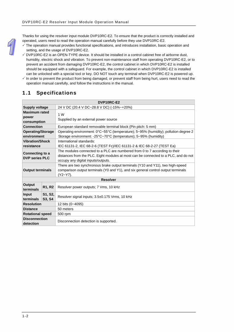
1.1 Specifications
DVP10RC-E2 Supply voltage 24 V DC (20.4 V DC~28.8 V DC) (-15%~+20%) Maximum rated power consumption
1 W Supplied by an external power source
Connection European standard removable terminal block (Pin pitch: 5 mm) Operating/Storage environment
Operating environment: 0°C~55°C (temperature); 5~95% (humidity); pollution degree 2 Storage environment: -25°C~70°C (temperature); 5~95% (humidity)
Vibration/Shock resistance
International standards: IEC 61131-2, IEC 68-2-6 (TEST Fc)/IEC 61131-2 & IEC 68-2-27 (TEST Ea)
Connecting to a DVP series PLC
The modules connected to a PLC are numbered from 0 to 7 according to their distances from the PLC. Eight modules at most can be connected to a PLC, and do not occupy any digital inputs/outputs.
Output terminals There are two synchronous brake output terminals (Y10 and Y11), two high-speed comparison output terminals (Y0 and Y1), and six general control output terminals (Y2~Y7).
Resolver Output terminals R1, R2 Resolver power outputs; 7 Vms, 10 kHz
Input terminals
S1, S2, S3, S4 Resolver signal inputs; 3.5±0.175 Vrms, 10 kHz
Resolution 12 bits (0~4095) Distance 50 meters Rotational speed 500 rpm Disconnection detection Disconnection detection is supported.
1-2

Chapter 1 In t roduct ion
1.2 Dimensions
7062
10698
78
90
61.511
0
Unit:mm
0 1 2 3 4 5 6 7
1011
1.3 Profile
Model namePOWE LED indicator, RUN LED indicator, and ERROR LED indicator
I/O terminal number
Removable terminal block
Mounting hole
Mounting groove(35 mm)
Extension port
Clip
Extension port
10RC-E20 1 2 3 4 5 6 7
1011
0 1 2 3 4 5 6 7
1011
Output LED indicator
1-3

DVP10RC-E2 Resolver Input Module Operat ion Manual
1.4 Arrangement of the I/O Terminals
D-D+SG0V24V
DVP10RC-E2 (1RI/10DO)
R2R1
Y3Y2Y1Y0ZPUP Y11Y10Y7Y6Y5Y4
D-D+ R2R1D-D+ R2R1D-D+ R2R1D-D+ R2R1D-D+ R2R1D-D+ R2R1D-D+ R2R1 S2 S4 S3 S1
1.5 Wiring I/O Terminals
Wiring input terminals
Wiring output terminals
ZP
Y0
UP
+
NPN output
DC power supplyDC load
1.6 LED Indicators and Troubleshooting
LED indicators
LED indicator Color Description
POWER Green The POWER LED indicator indicates whether there is power supplied to the CPU board.
RUN Green The RUN LED indicator indicates whether the module is running. ERROR Red The ERROR LED indicator indicates whether an error occrus.
Y0~Y7, and Y10~Y11 Red An output LED indicator indicates whether there is an output signal.
1-4

Chapter 1 In t roduct ion
RUN LED indicator and ERROR LED indicator RUN LED indicator
ERROR LED indicator Description Remedy
OFF ON
1. The external power supplied to the module is abnormal.
2. An input signal received by the resolver connected is abnormal. (The resolver used is disconnected.)
3. A rotational speed exceeds the range which can be resolved by the resolver connected.
Check external wiring.
ON Blinking Abnormal start Check whether the resolver connected rotates.
ON OFF The module is in a normal state. No remedy is needed.
1-5

DVP10RC-E2 Resolver Input Module Operat ion Manual
1-6
MEMO

Chapter 2 Control Registers Table of Contents 2.1 Table of Control Registers............................................................2-2 2.2 Functions..................................................................................2-6
2.2.1 Adjusting an Angle ...............................................................2-6 2.2.2 Rotational Speed..................................................................2-7 2.2.3 Counting the Number of Revolutions .......................................2-7 2.2.4 Forward/Backward Rotation ...................................................2-8 2.2.5 Cam Output ........................................................................2-8 2.2.6 Using Y0 and Y1 as High-speed Output Terminals .....................2-9 2.2.7 Controlling a Brake by Means of Y10/Y11 .............................. 2-10 2.2.8 Automatically Bringing out a Gliding Angle List ....................... 2-12 2.2.9 Offset Angle Percentage...................................................... 2-13
2.3 Descriptions of D9900~D9999 ................................................... 2-14
2-1

DVP10RC-E2 Resolver Input Module Operat ion Manual
2.1 Table of Control Registers
CR# Attribute Communication address Name Description Default
value
#0 R O H1000 Model code
The model code of a resolver input module is defined by the module’s system. DVP10RC-E2’s model code=H’0026
--
#1 R O H1001 Firmware version Hexadecimal value Current firmware version
--
#3 R X H1003 State flag Current state of DVP10RC-E2 --
#4 R X H1004 Digital value of a resolver
K0~K4095 --
#5 R X H1005 Angle of a resolver K0~K3599 (Unit: 0.1 degrees) -- #6 R X H1006 Angle of rotation K0~K3599 (Unit: 0.1 degrees) -- #7 R X H1007 Rotational speed Unit: rpm --
#8 R X H1008 Number of revolutionsK0~K32767 (Unit: Revolution) If the value in CR#8 overflows, it will become zero.
K0
#9 R X H1009
States of the output terminals on DVP10RC-E2 (1: ON; 0: OFF)
Bit 0~bit 7: Y0~Y7 Bit 8: Y10 Bit 9: Y11 Bit 10~bit 15: Reserved
--
#10 R O H100A Angular offset K-3599~K3599 (Unit: 0.1 degrees) K0
#11 R/W O H100B Target value for the adjustment of an angle
K0~K3599 (Unit: 0.1 degrees) K0
#13 R/W X H100D Mode of controlling a brake by means of Y10 and Y11
K0: No action K1: Inching mode K2: Continuous mode K3: Safe/Single mode
K0
#14 R/W O H100E Station period
K0~K1000 (Unit: 1 ms) Range: 1 ms~1000 ms K0: A system automatically brings out a station period according to a rotational speed.
K20
#15 R/W O H100F Station range K1~K100 (Unit: 0.1 degrees) K10
#16 R/W O H1010 Forward/Backward rotation
K0=Forward rotation K1=Backward rotation
K0
#17 R/W X H1011 Control command
K0: None K1: Stopping applying a brake (Y10 and Y11 are ON.) K2: Starting to apply a brake (Y10 and Y11 are OFF.) K3: Clearing the number of revolutions K4: Automatically bringing out a gliding angle list K5: Clearing an offset angle list K6: Clearing a gliding angle list K7: Adjusting an angle
K0
#20 R/W O H1014 Mode of communication
K0: MODBUS mode K1: DVP-F6SEG’s mode of communication
K1
#21 R/W O H1015 Communication station address
RS-485 communication address (1~254)
K1
2-2

Chapter 2 Contro l Regis ters
2-3
CR# Attribute Communication address Name Description Default
value
#22 R/W O H1016 Communication format
There are six types of communication rates (4,800~115,200 bps) b0: 4,800 bps b1: 9,600 bps (Default value) b2: 19,200 bps b3: 38,400 bps b4: 57,600 bps b5: 115,200 bps b6~b13: Reserved b14: The high eight bits in a CRC checksum is interchanged with the low eight bits in the CRC checksum. (Only effective in an RTU mode) b15=0: ASCII mode b15=1: RTU mode ASCII mode: 7 bits, even parity bit, 1 stop bit (7, E, 1) RTU mode: 8 bits, even parity bit, 1 stop bit (8, E, 1) Default value: H’0002.
See the description of C
R#22.
#23 R/W X H1017 Angle of advance K0~K3599 (Unit: 0.1 degrees) K1800#24 R/W X H1018 Angle of departure K0~K3599 (Unit: 0.1 degrees) K2500
#25 R/W O H1019 Way in which Y0 and Y1 operate
0: Angle comparison output terminals 1: High-speed output terminals
K0
#26 R/W O H101A
Start angle to which Y0 corresponds
K0~K3599 (Unit: 0.1 degrees) K0
#27 R/W O H101B
End angle to which Y0 corresponds
K0~K3599 (Unit: 0.1 degrees) K0
#28 R/W O H101C
Start angle to which Y1 corresponds
K0~K3599 (Unit: 0.1 degrees) K0
#29 R/W O H101D
End angle to which Y1 corresponds
K0~K3599 (Unit: 0.1 degrees) K0
#30 R/W O H101E Start angle to which Y2 corresponds
K0~K3599 (Unit: 0.1 degrees) K0
#31 R/W O H101F End angle to which Y2 corresponds
K0~K3599 (Unit: 0.1 degrees) K0
#32 R/W O H1020 Start angle to which Y3 corresponds
K0~K3599 (Unit: 0.1 degrees) K0
#33 R/W O H1021 End angle to which Y3 corresponds
K0~K3599 (Unit: 0.1 degrees) K0
#34 R/W O H1022 Start angle to which Y4 corresponds
K0~K3599 (Unit: 0.1 degrees) K0
#35 R/W O H1023 End angle to which Y4 corresponds
K0~K3599 (Unit: 0.1 degrees) K0
#36 R/W O H1024 Start angle to which Y5 corresponds
K0~K3599 (Unit: 0.1 degrees) K0
#37 R/W O H1025 End angle to which Y5 corresponds
K0~K3599 (Unit: 0.1 degrees) K0
#38 R/W O H1026 Start angle to which Y6 corresponds
K0~K3599 (Unit: 0.1 degrees) K0
#39 R/W O H1027 End angle to which Y6 corresponds
K0~K3599 (Unit: 0.1 degrees) K0
#40 R/W O H1028 Start angle to which Y7 corresponds
K0~K3599 (Unit: 0.1 degrees) K0

DVP10RC-E2 Resolver Input Module Operat ion Manual
2-4
CR# Attribute Communication address Name Description Default
value
#41 R/W O H1029 End angle to which Y7 corresponds
K0~K3599 (Unit: 0.1 degrees) K0
#42 R/W O H102A Minimum rotational speed
Range: 1~200 (Unit: rpm) K0
#43 R/W O H102B
Gliding angle corresponding to a minimum rotational speed
K0~K3599 (Unit: 0.1 degrees) K0
#44 R/W O H102C Maximum rotational speed
Range: 1~200 (Unit: rpm) K0
#45 R/W O H102D
Gliding angle corresponding to a maximum rotational speed
K0~K3599 (Unit: 0.1 degrees) K0
#48 R/W O H102E Offset angle percentage
K0 = 0% (No offset) K1 = 25% (Offset) K2 = 50% (Offset) K3 = 100% (Offset)
K2
#49 R/W O H1031 Stop angle K0~K3599 (Unit: 0.1 degrees) K0 #50 R/W O H1032 Gliding angle (10 rpm) K0~K3599 (Unit: 0.1 degrees) K0 #51 R/W O H1033 Gliding angle (20 rpm) K0~K3599 (Unit: 0.1 degrees) K0 #52 R/W O H1034 Gliding angle (30 rpm) K0~K3599 (Unit: 0.1 degrees) K0 #53 R/W O H1034 Gliding angle (40 rpm) K0~K3599 (Unit: 0.1 degrees) K0 #54 R/W O H1035 Gliding angle (50 rpm) K0~K3599 (Unit: 0.1 degrees) K0 #55 R/W O H1036 Gliding angle (60 rpm) K0~K3599 (Unit: 0.1 degrees) K0 #56 R/W O H1037 Gliding angle (70rpm) K0~K3599 (Unit: 0.1 degrees) K0 #57 R/W O H1038 Gliding angle (80 rpm) K0~K3599 (Unit: 0.1 degrees) K0 #58 R/W O H1039 Gliding angle (90 rpm) K0~K3599 (Unit: 0.1 degrees) K0
#59 R/W O H103A Gliding angle (100 rpm)
K0~K3599 (Unit: 0.1 degrees) K0
#60 R/W O H103B Gliding angle of braking (110 rpm)
K0~K3599 (Unit: 0.1 degrees) K0
#61 R/W O H103C Gliding angle (120 rpm)
K0~K3599 (Unit: 0.1 degrees) K0
#62 R/W O H103D Gliding angle (130 rpm)
K0~K3599 (Unit: 0.1 degrees) K0
#63 R/W O H103E Gliding angle (140 rpm)
K0~K3599 (Unit: 0.1 degrees) K0
#64 R/W O H103F Gliding angle (150 rpm)
K0~K3599 (Unit: 0.1 degrees) K0
#65 R/W O H1040 Gliding angle (160 rpm)
K0~K3599 (Unit: 0.1 degrees) K0
#66 R/W O H1041 Gliding angle (170 rpm)
K0~K3599 (Unit: 0.1 degrees) K0
#67 R/W O H1042 Gliding angle (180 rpm)
K0~K3599 (Unit: 0.1 degrees) K0
#68 R/W O H1043 Gliding angle (190 rpm)
K0~K3599 (Unit: 0.1 degrees) K0
#69 R/W O H1044 Gliding angle (200 rpm)
K0~K3599 (Unit: 0.1 degrees) K0
#70 R/W O H1046 Rotational speed of an offset angle
K1~k200 (Unit: rpm) K0
#71 R/W O H1047 Offset angle K0~K3599 (Unit: 0.1 degrees) K0

Chapter 2 Contro l Regis ters
2-5
CR# Attribute Communication address Name Description Default
value#100~ #119
R/W O H1064~ H1077
Number of revolutions set for Y0
K0~K32767 K0
#120~ #139
R/W O H1078~ H108B
Number of revolutions set for Y1
K0~K32767 K0
#140~ #159
R/W O H108C~ H109F
Start angle corresponding to the number of revolutions set for Y0
K0~K3599 (Unit: 0.1 degrees) K0
#160~ #179
R/W O H1080~ H10B3
Start angle corresponding to the number of revolutions set for Y1
K0~K3599 (Unit: 0.1 degrees) K0
#180~ #199
R/W O H10B4~ H10C7
End angle corresponding to the number of revolutions set for Y0
K0~K3599 (Unit: 0.1 degrees) K0
#200~ #219
R/W O H10C8~ H10DB
End angle corresponding to the number of revolutions set for Y1
K0~K3599 (Unit: 0.1 degrees) K0
Symbols: O: The register is a retentive register. X: The register is not a retentive register. R: User can read the data in the control register by means of the instruction FROM, or RS-485
communication. (Only 03 (reading) is supported.) W: Users can write data to the control register by means of the instruction TO.
※ CR#3: State flag Bit Description 1 0
Bit 0 External power supply flag Abnormal Normal Bit 1 Abnormal start Abnormal Normal
Bit 2 An input signal received by the resolver connected is abnormal. (The resolver used is disconnected.)
Abnormal Normal
Bit 3 A rotational speed exceeds the range which can be resolved by the resolver connected.
Abnormal Normal
Bit 4 Station judgment flag Static Not static Bit 5~bit 15 Reserved -- --
DVP10RC-E2 Resolver Input Module Operat ion Manual
2.2 Functions
2.2.1 Adjusting an Angle
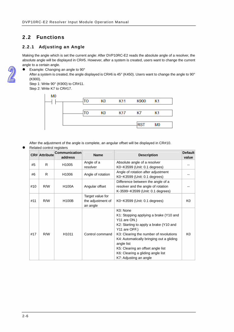
Making the angle which is set the current angle: After DVP10RC-E2 reads the absolute angle of a resolver, the absolute angle will be displayed in CR#5. However, after a system is created, users want to change the current angle to a certain angle. Example: Changing an angle to 90°
After a system is created, the angle displayed is CR#6 is 45° (K450). Users want to change the angle to 90° (K900). Step 1: Write 90° (K900) to CR#11. Step 2: Write K7 to CR#17.
After the adjustment of the angle is complete, an angular offset will be displayed in CR#10. Related control registers
CR# Attribute Communication address Name Description Default
value
#5 R H1005 Angle of a resolver
Absolute angle of a resolver K0~K3599 (Unit: 0.1 degrees)
--
#6 R H1006 Angle of rotation Angle of rotation after adjustment K0~K3599 (Unit: 0.1 degrees)
--
#10 R/W H100A Angular offset Difference between the angle of a resolver and the angle of rotation K-3599~K3599 (Unit: 0.1 degrees)
--
#11 R/W H100B Target value for the adjustment of an angle
K0~K3599 (Unit: 0.1 degrees) K0
#17 R/W H1011 Control command
K0: None K1: Stopping applying a brake (Y10 and Y11 are ON.) K2: Starting to apply a brake (Y10 and Y11 are OFF.) K3: Clearing the number of revolutions K4: Automatically bringing out a gliding angle list K5: Clearing an offset angle list K6: Clearing a gliding angle list K7: Adjusting an angle
K0
2-6
Chapter 2 Contro l Regis ters
2.2.2 Rotational Speed
DVP10RC-E2 can detect the current rotational speed of a resolver. When the angle of the resolver is the angle of advance, DVP10RC-E2 starts to detect the rotational speed of the resolver. DVP10RC-E2 applies the brake connected when the angle of the resolver is the angle of departure. The current rotational speed of the resolver is displayed in CR#7. Related control registers
CR# Attribute Communication address Name Description Default
value#7 R H1007 Rotational speed Unit: rpm --
#23 R/W H1017 Angle of advance K0~K3599 (Unit: 0.1 degrees) K1800#24 R/W H1018 Angle of departure K0~K3599 (Unit: 0.1 degrees) K2500
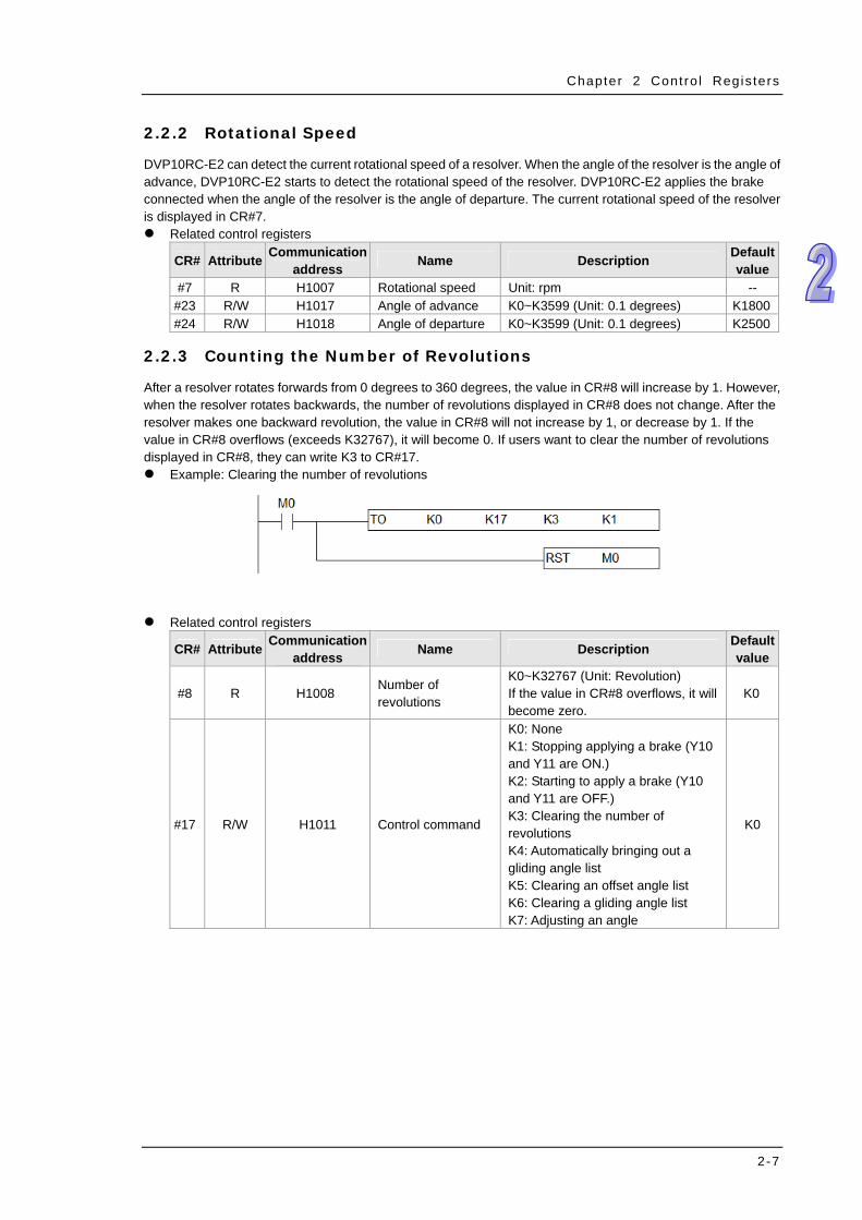
2.2.3 Counting the Number of Revolutions
After a resolver rotates forwards from 0 degrees to 360 degrees, the value in CR#8 will increase by 1. However, when the resolver rotates backwards, the number of revolutions displayed in CR#8 does not change. After the resolver makes one backward revolution, the value in CR#8 will not increase by 1, or decrease by 1. If the value in CR#8 overflows (exceeds K32767), it will become 0. If users want to clear the number of revolutions displayed in CR#8, they can write K3 to CR#17. Example: Clearing the number of revolutions
Related control registers
CR# Attribute Communication address Name Description Default
value
#8 R H1008 Number of revolutions
K0~K32767 (Unit: Revolution) If the value in CR#8 overflows, it will become zero.
K0
#17 R/W H1011 Control command
K0: None K1: Stopping applying a brake (Y10 and Y11 are ON.) K2: Starting to apply a brake (Y10 and Y11 are OFF.) K3: Clearing the number of revolutions K4: Automatically bringing out a gliding angle list K5: Clearing an offset angle list K6: Clearing a gliding angle list K7: Adjusting an angle
K0
2-7

DVP10RC-E2 Resolver Input Module Operat ion Manual
2.2.4 Forward/Backward Rotation
The system controlled by DVP10RC-E2 generally rotate forwards (0°90°180°270°0°). If it needs to rotate backwards, users have to write 1 to CR#16, otherwise problems may occur in other related control.
0o
90o
180o
270o
Forward rotation Backward rotation0o
90o
180o
270o
Related control register
CR# Attribute Communication address Name Description Default
value
#16 R H1010 Forward/Backward rotation
K0=Forward rotation K1=Backward rotation
K0
2.2.5 Cam Output
Users can set angle ranges for Y0~Y7. If the angle of a resolver is in the range of θA~θB, the output terminal corresponding to the angle range will be ON. If the angle of a resolver is not in the range of θA~θB, the output terminal corresponding to the range will be OFF. If the users want to use Y0 and Y1 as angle comparison output terminals, they have to write K0 to CR#25.
ON
A B
Related control registers
CR# Attribute Communication address Name Description Default
value
#25 R/W H1019 Way in which Y0 and Y1 operate
0: Angle comparison output terminals 1: High-speed output terminals
K0
#26 R/W H101A Start angle to which Y0 corresponds
K0~K3599 (Unit: 0.1 degrees) K0
#27 R/W H101B End angle to which Y0 corresponds
K0~K3599 (Unit: 0.1 degrees) K0
#28 R/W H101C Start angle to which Y1 corresponds
K0~K3599 (Unit: 0.1 degrees) K0
2-8
Chapter 2 Contro l Regis ters
CR# Attribute Communication address Name Description Default
value
#29 R/W H101D End angle to which Y1 corresponds
K0~K3599 (Unit: 0.1 degrees) K0
#30 R/W H101E Start angle to which Y2 corresponds
K0~K3599 (Unit: 0.1 degrees) K0
#31 R/W H101F End angle to which Y2 corresponds
K0~K3599 (Unit: 0.1 degrees) K0
#32 R/W H1020 Start angle to which Y3 corresponds
K0~K3599 (Unit: 0.1 degrees) K0
#33 R/W H1021 End angle to which Y3 corresponds
K0~K3599 (Unit: 0.1 degrees) K0
#34 R/W H1022 Start angle to which Y4 corresponds
K0~K3599 (Unit: 0.1 degrees) K0
#35 R/W H1023 End angle to which Y4 corresponds
K0~K3599 (Unit: 0.1 degrees) K0
#36 R/W H1024 Start angle to which Y5 corresponds
K0~K3599 (Unit: 0.1 degrees) K0
#37 R/W H1025 End angle to which Y5 corresponds
K0~K3599 (Unit: 0.1 degrees) K0
#38 R/W H1026 Start angle to which Y6 corresponds
K0~K3599 (Unit: 0.1 degrees) K0
#39 R/W H1027 End angle to which Y6 corresponds
K0~K3599 (Unit: 0.1 degrees) K0
#40 R/W H1028 Start angle to which Y7 corresponds
K0~K3599 (Unit: 0.1 degrees) K0
#41 R/W H1029 End angle to which Y7 corresponds
K0~K3599 (Unit: 0.1 degrees) K0
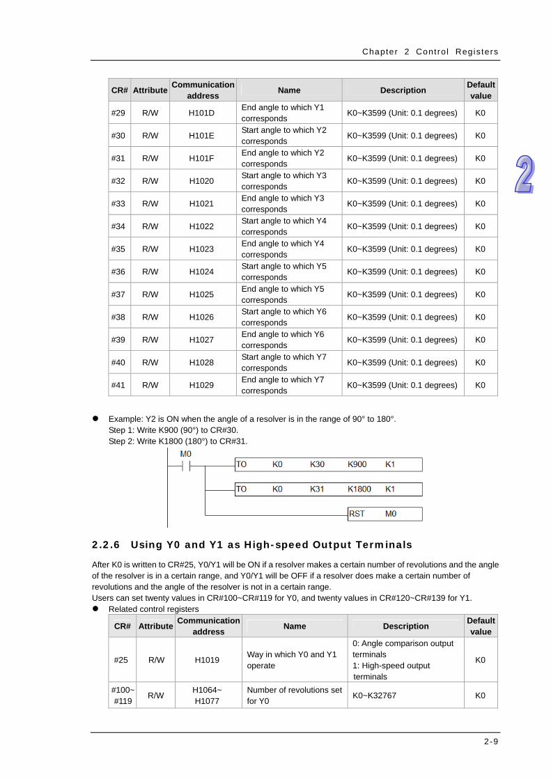
Example: Y2 is ON when the angle of a resolver is in the range of 90° to 180°. Step 1: Write K900 (90°) to CR#30. Step 2: Write K1800 (180°) to CR#31.
2.2.6 Using Y0 and Y1 as High-speed Output Terminals
After K0 is written to CR#25, Y0/Y1 will be ON if a resolver makes a certain number of revolutions and the angle of the resolver is in a certain range, and Y0/Y1 will be OFF if a resolver does make a certain number of revolutions and the angle of the resolver is not in a certain range. Users can set twenty values in CR#100~CR#119 for Y0, and twenty values in CR#120~CR#139 for Y1. Related control registers
CR# Attribute Communicationaddress Name Description Default
value
#25 R/W H1019 Way in which Y0 and Y1 operate
0: Angle comparison output terminals 1: High-speed output terminals
K0
#100~ #119
R/W H1064~ H1077
Number of revolutions set for Y0
K0~K32767 K0
2-9

DVP10RC-E2 Resolver Input Module Operat ion Manual
2-10
CR# Attribute Communication address Name Description Default
value #120~ #139
R/W H1078~ H108B
Number of revolutions set for Y1
K0~K32767 K0
#140~ #219
R/W H108C~ H10DB
Angle corresponding to the number of revolutions set for Y0/Y1
K0~K3599 (Unit: 0.1 degrees)
K0
Example: If the resolver connected makes ten revolutions, and the angle of the resolver is in the range of 0° to 30°, Y0 will be ON. If the resolver connected makes twenty revolutions, and the angle of the resolver is in the range of 30° to 60°, Y0 will be ON. If the resolver connected makes forty revolutions, and the angle of the resolver is in the range of 60° to 90°, Y0 will be ON. If the resolver connected makes forty-six revolutions, and the angle of the resolver is in the range of 90° to 160°, Y0 will be ON.
Number of revolutions set for Y0
Start angle corresponding to the number of revolutions set for Y0
End angle corresponding to the number of revolutions set for Y0
10 0° 30° 20 30° 60° 40 60° 90° 46 90° 160°
2.2.7 Controlling a Brake by Means of Y10/Y11
Description: A brake is controlled by Y10 and Y11. Y10 and Y11 are ON or OFF simultaneously. Output terminal State Control
Y10/Y11 OFF Applying a brake Y10/Y11 ON Not applying a brake

Chapter 2 Contro l Regis ters
CR#13: Mode of controlling a brake by means of Y10 and Y11 No action (K0): The brake connected is applied. Y10 and Y11 are OFF continuously. Inching mode (K1): Y10 and Y11 are ON continuously. Continuous mode (K2): The brake connected is not applied initially. Y10 and Y11 are ON continuously.
If K2 is written to CR#17, the brake connected will be applied (Y10 and Y11 will be OFF) according to the stop angle, the gliding angle, and the offset angle which are set by users after the angle of advance appears again. When the punching machine used stops, Y10 and Y11 are OFF. If the users write K1 to CR#17, the application of the brake connected will be stopped, Y10 and Y11 will be ON, and DVP10RC-E2 will wait for the next brake command.
Safe/Single mode (K3): Y10 are Y11 are ON initially. The brake connected will be applied automatically (Y10 and Y11 will be OFF) according to the stop angle, the gliding angle, and the offset angle which are set by users after the angle of advance appears again. When the punching machine used stops, Y10 and Y11 are OFF. If the users write K1 to CR#17, the application of the brake connected will be stopped, Y10 and Y11 will be ON, and the brake connected will be applied automatically after the angle of advance appears again.
CR#13 Mode of controlling a brake States of Y10 and Y11
K0 No action The brake connected is applied (Y10 and Y11 are OFF continuously).
K1 Inching mode The brake connected is not applied (Y10 and Y11 are ON continuously).
K2 Continuous mode
Initial states: Y10 and Y11 are ON (The brake connected is not applied). Writing K2 to CR#17: The brake connected is applied (Y10 and Y11 are OFF) according to the stop angle, the gliding angle, and the offset angle which are set by users. Writing K1 to CR#17: The application of the brake connected is stopped (Y10 and Y11 are ON).
K3 Safe/Single mode
The brake connected is applied automatically (Y10 and Y11 are OFF) according to the stop angle, the gliding angle, and the offset angle which are set by users. Initial states: Y10 are Y11 are ON (The brake connected is not applied). Writing K1 to CR#17: The application of the brake connected is stopped (Y10 and Y11 are ON).
Related control registers
CR# Attribute Communication address Name Description Default
value
#13 R/W H100D Mode of controlling a brake by means of Y10 and Y11
K0: No action K1: Inching mode K2: Continuous mode K3: Safe/Single mode
K0
#17 R/W H1011 Control command
K0: None K1: Stopping applying a brake (Y10 and Y11 are ON.) K2: Starting to apply a brake (Y10 and Y11 are OFF.) K3: Clearing the number of revolutions K4: Automatically bringing out a gliding angle list K5: Clearing an offset angle list K6: Clearing a gliding angle list K7: Adjusting an angle
K0
2-11

DVP10RC-E2 Resolver Input Module Operat ion Manual
CR# Attribute Communication address Name Description Default
value
#48 R/W H102E Offset angle percentage
K0 = 0% (No offset) K1 = 25% (Offset) K2 = 50% (Offset) K3 = 100% (Offset)
K2
#49 R/W H1031 Stop angle K0~K3599 (Unit: 0.1 degrees) K0 #50~ #69
R/W H1032 H1045
Gliding angle (10~200 rpm)
K0~K3599 (Unit: 0.1 degrees) K0
#70 R/W H1032 Rotational speed of an offset angle
K1~k200 (Unit: rpm) K0
#71 R H1033 Offset angle K0~K3599 (Unit: 0.1 degrees) K0
Angle at which a brake is applied Angel at which a brake is applied=Stop angle-Gliding angle-Offset angle Example: The stop angle set in CR#49 is 100 degrees, the gliding angle set in CR#50 is 10 degrees, the gliding angle set in CR#51 is 20 degrees, and the offset angle set in CR71 is 0 degrees. 10 rpm: The angle at which the brake connected is applied is 90 degrees. 20 rpm: The angle at which the brake connected is applied is 80 degrees. Users have to set gliding angle, a stop angle, and an offset angle according to the system used.
2.2.8 Automatically Bringing out a Gliding Angle List
Description: If users want to control a brake, they have to write twenty gliding angles to CR#50~CR#69. However, twenty gliding angles can be brought into CR#50~CR#69 easily if the users follow the steps below. Step 1: Write K6 to CR#17. Step 2: The resolver connected completes one stroke at the rotational speed A. The rotational speed A is written to CR#42, and the difference between the angle at which the resolver connected needs to stop and the actual angle at which the resolver connected stops is written to CR#43. Step 3: The resolver connected completes one stroke at the rotational speed B. The rotational speed B is written to CR#44, and the difference between the angle at which the resolver connected needs to stop and the actual angle at which the resolver connected stops is written to CR#45. Step 4: Write K4 to CR#17. After the users complete the steps above, they can read the gliding angles in CR#50~CR#69.
Related control registers CR# Description #17 Control command #42 Rotational speed A #43 Gliding angle corresponding to the rotational speed A #44 Rotational speed B #45 Gliding angle corresponding to the rotational speed B
#50~#69 Gliding angle (10~200 rpm)
2-12
Chapter 2 Contro l Regis ters
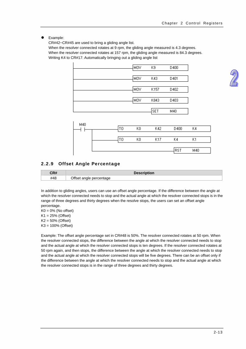
Example: CR#42~CR#45 are used to bring a gliding angle list. When the resolver connected rotates at 9 rpm, the gliding angle measured is 4.3 degrees. When the resolver connected rotates at 157 rpm, the gliding angle measured is 84.3 degrees. Writing K4 to CR#17: Automatically bringing out a gliding angle list
2.2.9 Offset Angle Percentage
CR# Description #48 Offset angle percentage
In addition to gliding angles, users can use an offset angle percentage. If the difference between the angle at which the resolver connected needs to stop and the actual angle at which the resolver connected stops is in the range of three degrees and thirty degrees when the resolve stops, the users can set an offset angle percentage. K0 = 0% (No offset) K1 = 25% (Offset) K2 = 50% (Offset) K3 = 100% (Offset) Example: The offset angle percentage set in CR#48 is 50%. The resolver connected rotates at 50 rpm. When the resolver connected stops, the difference between the angle at which the resolver connected needs to stop and the actual angle at which the resolver connected stops is ten degrees. If the resolver connected rotates at 50 rpm again, and then stops, the difference between the angle at which the resolver connected needs to stop and the actual angle at which the resolver connected stops will be five degrees. There can be an offset only if the difference between the angle at which the resolver connected needs to stop and the actual angle at which the resolver connected stops is in the range of three degrees and thirty degrees.
2-13
DVP10RC-E2 Resolver Input Module Operat ion Manual
2-14
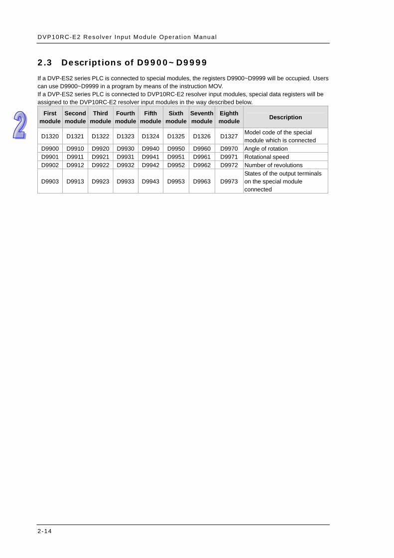
2.3 Descriptions of D9900~D9999
If a DVP-ES2 series PLC is connected to special modules, the registers D9900~D9999 will be occupied. Users can use D9900~D9999 in a program by means of the instruction MOV. If a DVP-ES2 series PLC is connected to DVP10RC-E2 resolver input modules, special data registers will be assigned to the DVP10RC-E2 resolver input modules in the way described below.
First module
Second module
Third module
Fourth module
Fifth module
Sixth module
Seventh module
Eighth module Description
D1320 D1321 D1322 D1323 D1324 D1325 D1326 D1327Model code of the special module which is connected
D9900 D9910 D9920 D9930 D9940 D9950 D9960 D9970 Angle of rotation D9901 D9911 D9921 D9931 D9941 D9951 D9961 D9971 Rotational speed D9902 D9912 D9922 D9932 D9942 D9952 D9962 D9972 Number of revolutions
D9903 D9913 D9923 D9933 D9943 D9953 D9963 D9973States of the output terminals on the special module connected