response om english rev ta-10 - itc the point of care
TRANSCRIPT
Operator’s Manual English
TABLE OF CONTENTS INTENDED USE.............................................................. 2 SUMMARY AND EXPLANATION.................................... 2 PRINCIPLES OF OPERATION ....................................... 2 ATTENTION LABEL ........................................................ 4 SPECIFICATIONS........................................................... 5 GETTING STARTED....................................................... 5 SETTING SUPERVISOR OPTIONS ............................. 11 SETTING OUTPUT OPTIONS ...................................... 18 SETTING PROGRAM OPTIONS .................................. 20 CUSTOMIZING THE PRINTED HEADING ................... 21 OPERATION ................................................................. 21 QUALITY CONTROL (QC)............................................ 27 OPERATING PRECAUTIONS....................................... 29 LIMITATIONS................................................................ 29 RESULTS MANAGEMENT ........................................... 30 DEFAULT SETTINGS ................................................... 32 TROUBLESHOOTING .................................................. 33 SYSTEM TESTS ........................................................... 35 MAINTENANCE ............................................................ 38 SPECIFICATIONS FOR PERIPHERALS ...................... 39 SAFETY STANDARDS ................................................. 41 INDEX ........................................................................... 42
This manual is published by International Technidyne Corporation (ITC) for use with the HEMOCHRON Response V2.00 or above. Questions or comments regarding the contents of this manual can be directed to the address at the back of this manual or to your ITC representative.
HEMOCHRON® and RxDx® are registered trademarks of ITC.
idms™ is a trademark of ITC.
Celite® is registered trademark of Celite Corporation.
©2000, 2001, 2002, 2003, 2004. This document is the copyright of ITC and must not be copied or reproduced in any form without prior consent. ITC reserves the right to make technical improvements to this equipment and documentation without prior notice as part of a continuous program of product development.
Printed From ITC Intranet
2
INTENDED USE The HEMOCHRON® Response Whole Blood Coagulation System is a dual-well microprocessor-controlled coagulation testing instrument with an integral test type barcode reader, RS232 communication interface capability, and a printer. The system runs coagulation tests such as Activated Clotting Time (ACT), Activated Partial Thromboplastin Time (APTT), Prothrombin Time (PT) and other specialty tests that are currently available from ITC.
SUMMARY AND EXPLANATION Events that lead to formation of a blood clot are simplified in coagulation theory into two interactive coagulation cascades. The Activated Clotting Time (ACT), Activated Partial Thromboplastin Time (APTT) and Prothrombin Time (PT) tests are general coagulation screening tests that are used to measure the functionality of these cascades.
The ACT test is the method of choice for monitoring heparin therapy. Administration of heparin to maintain hemostasis during cardiac surgery and cardiac angioplasty procedures can pose significant risk to the patient. Since individual patients can vary as much as twelve-fold in heparin sensitivity, overdosing heparin can result in dangerous bleeding and underdosing heparin can lead to thrombosis.
ACT is performed by adding a clotting activator such as Celite®, silica, kaolin, or glass particles to a blood sample and then measuring the length of time required for clot formation. The particular clotting activator that is used influences the time required for clot formation. Celite (diatomaceous earth) is the standard ACT reagent used for high level heparin monitoring because of its excellent activating properties. However, serine protease inhibitors such as aprotinin that may be administered to certain patients to decrease postoperative bleeding can prolong the Celite activated ACT. When aprotinin is on-board, a kaolin-activated ACT tube should be used.
The APTT test measures the intrinsic coagulation pathway and involves all coagulation factors except factors VII and III (tissue factor). The APTT test improves the earlier PTT test through use of a contact activating substance which standardizes activation of Factor XII to provide a more precise and sensitive assay for low level heparin monitoring.
The PT test measures the extrinsic coagulation pathway and is sensitive to coagulation factors VII, X, V, II, and fibrinogen. PT results may be abnormal in patients with liver disease or Vitamin K deficiency, and the test is widely used to monitor oral anticoagulant therapy.
Under clinical conditions, the coagulation cascade may be affected by either naturally occurring or administered procoagulants or anticoagulants. Endogenous changes in hemostasis, such as disseminated intravascular coagulation, can result in extreme clotting factor depletion. In order to determine which pathway is being affected, a panel of coagulation assays may be performed. Results of these tests are used to diagnose the hemostatic abnormality and to determine the appropriate therapeutic intervention.
PRINCIPLES OF OPERATION The patented HEMOCHRON clot detection module contains two test wells into which disposable unitized coagulation test tubes can be inserted. The test tubes (provided in a separately purchased test kit) contain reagents for a particular test and a precision magnet. Immediately after the sample is added to the test tube, the START button is pressed, the test tube is agitated, and the test tube is placed into the test well by the operator. There, it is automatically rotated at a controlled speed and incubated at 37 °C ±1.0 °C.
When a fibrin clot begins to form, it causes the magnet in the test tube to be displaced. Two magnetic detectors located in the test well continuously monitor the precise magnet position. When a specific displacement of the magnet occurs, the elapsed time between the beginning of the test and the clot endpoint is displayed as the coagulation time (in seconds). The instrument also emits an audible beep when clot formation occurs, indicating the end of the test.
The coagulation time is displayed on the LCD screen. The operator may choose to print the result (if automatic printing of results is not specified) or simply proceed to the next desired assay.
Printed From ITC Intranet
3
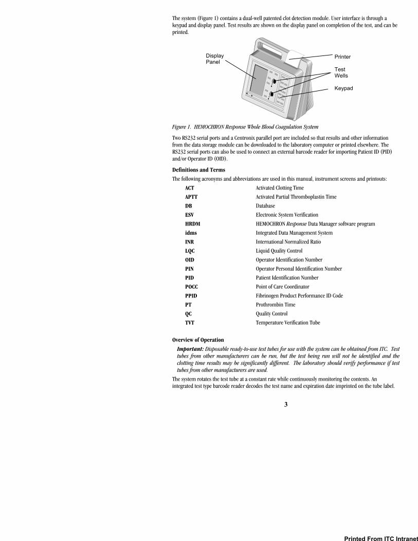
The system (Figure 1) contains a dual-well patented clot detection module. User interface is through a keypad and display panel. Test results are shown on the display panel on completion of the test, and can be printed.
Figure 1. HEMOCHRON Response Whole Blood Coagulation System
Two RS232 serial ports and a Centronix parallel port are included so that results and other information from the data storage module can be downloaded to the laboratory computer or printed elsewhere. The RS232 serial ports can also be used to connect an external barcode reader for importing Patient ID (PID) and/or Operator ID (OID).
Definitions and Terms
The following acronyms and abbreviations are used in this manual, instrument screens and printouts:
ACT Activated Clotting Time
APTT Activated Partial Thromboplastin Time
DB Database
ESV Electronic System Verification
HRDM HEMOCHRON Response Data Manager software program
idms Integrated Data Management System
INR International Normalized Ratio
LQC Liquid Quality Control
OID Operator Identification Number
PIN Operator Personal Identification Number
PID Patient Identification Number
POCC Point of Care Coordinator
PPID Fibrinogen Product Performance ID Code
PT Prothrombin Time
QC Quality Control
TVT Temperature Verification Tube
Overview of Operation
Important: Disposable ready-to-use test tubes for use with the system can be obtained from ITC. Test tubes from other manufacturers can be run, but the test being run will not be identified and the clotting time results may be significantly different. The laboratory should verify performance if test tubes from other manufacturers are used.
The system rotates the test tube at a constant rate while continuously monitoring the contents. An integrated test type barcode reader decodes the test name and expiration date imprinted on the tube label.
Printer Test Wells Keypad
Display Panel
Printed From ITC Intranet

4
After a clot forms, the instrument beeps and the clotting time is displayed on the display panel. The result is also stored in the system database with the date and time the test was performed, and the assay type. If entered, the PID and OID are stored with the test result.
Features
The system has a number of performance and convenience features:
• The system is portable for bedside use • A multi-test menu is resident on the system • Fresh whole blood or citrated whole blood can be used with the appropriate test tubes • A sample size of up to 2 mL of whole blood is required • Test name and expiration date are automatically read when ITC barcoded test tubes are used • Successful or errant results are automatically stamped with date and time • Results are available in minutes • Results are displayed appropriately as whole blood or plasma equivalent or INR (PT assay only) • Results of 600 patient tests and 300 QC tests can be stored for each well, with optional entry of
PID, OID, and user notes • Dose-response calculations are performed with the RxDx® module (if activated) • 504 operator identification codes can be stored with OID/PIN and permissions • Operator lockout can be configured by OID, valid OID, or PIN, using HRDM V3.0 or higher
software or the keypad • QC lockout can be configured at one or two levels by time interval • Stored results can be reviewed by test type, PID, OID, or date • Stored results can be downloaded to a personal computer • System self checks are automatically performed • An ESV tube is available to check test well operation and detector electronics • A Temperature Verification Tube (TVT) can be additionally used to check test well temperature • The display is illuminated for viewing in low light • The display can indicate the percentage of battery power remaining numerically or graphically • The user is alerted when the battery is low • The system includes an on-board printer • Two external serial ports and a Centronics parallel port are provided • Patient/QC test reports can be created using a personal computer and ITC data management
software programs
ATTENTION LABEL
An attention label on the rear of the HEMOCHRON Response instrument alerts users to accompanying documentation:
Before using the HEMOCHRON Response instrument, it is essential that the contents of this Operator’s Manual are read and understood by the operator.
Handle and open the container with care.
Printed From ITC Intranet
5
SPECIFICATIONS Specifications for the HEMOCHRON Response Whole Blood Coagulation System are listed below.
Dimensions and Weight
Depth 19 cm (7.5 in) Width 27 cm (10.5 in) Height 22 cm (8.7 in) Weight 2.90 kg (6.4 lbs)
Operation
Test Wells 2
Timing Range 22 seconds to 1500 seconds
Incubation Temperature 37 °C ±1.0 °C
Incubation Warm-Up Time 30 seconds to 90 seconds
Full-Charge Operating Time 8 hours (minimum)
Battery Life 500 recharges
Throughput (Full Charge) 49 test cycles (at 150 sec per test)
17 test cycles (> 500 sec per test)
AC/DC Power Module
Input Power 90 to 264 VAC, 50/60 Hz, 1.2 Amps maximum
Output Power +12 Volts DC, 3.5 Amps maximum (42 Watts, 144 BTU/hr)
Environmental
Ambient Temperature 15 to 30 °C
Note: For more technical information, refer to the HEMOCHRON Response Whole Blood Coagulation System Service Manual.
GETTING STARTED
Unpacking and Inspection
Before unpacking the system, determine the area where the system will be located. You will need a level and flat area that is approximately 30 cm (12 in) wide, 30 cm (12 in) deep, and 30 cm (12 in) high.
To Unpack the Instrument: 1. Unpack the carton. 2. Inspect each component for damage when unpacking. If damage is observed, contact your
shipper or service representative immediately. 3. Place the instrument where it is to be located. 4. Remove protective packaging. 5. Examine the packaging material to be sure that the power supply, connecting cables or other
components have been removed. The materials that are provided are listed on the following page. Note: Do not discard the packing material. It should be kept for shipping the instrument to ITC, if repair is necessary.
Printed From ITC Intranet
6
Materials Provided
RS232 Computer Interface Cable 1 Materials Required But Not Provided
Article Quantity
Electronic System Verification Tube 1
HEMOCHRON Test Tube Assays As Needed
HEMOCHRON Liquid Quality Control As Needed
Temperature Verification Tube As Needed
idms v7.1 or later (Integrated Data Management System) As Needed
Note: A power cord is provided only in those countries that provide 110 volt power.
Connecting External Components
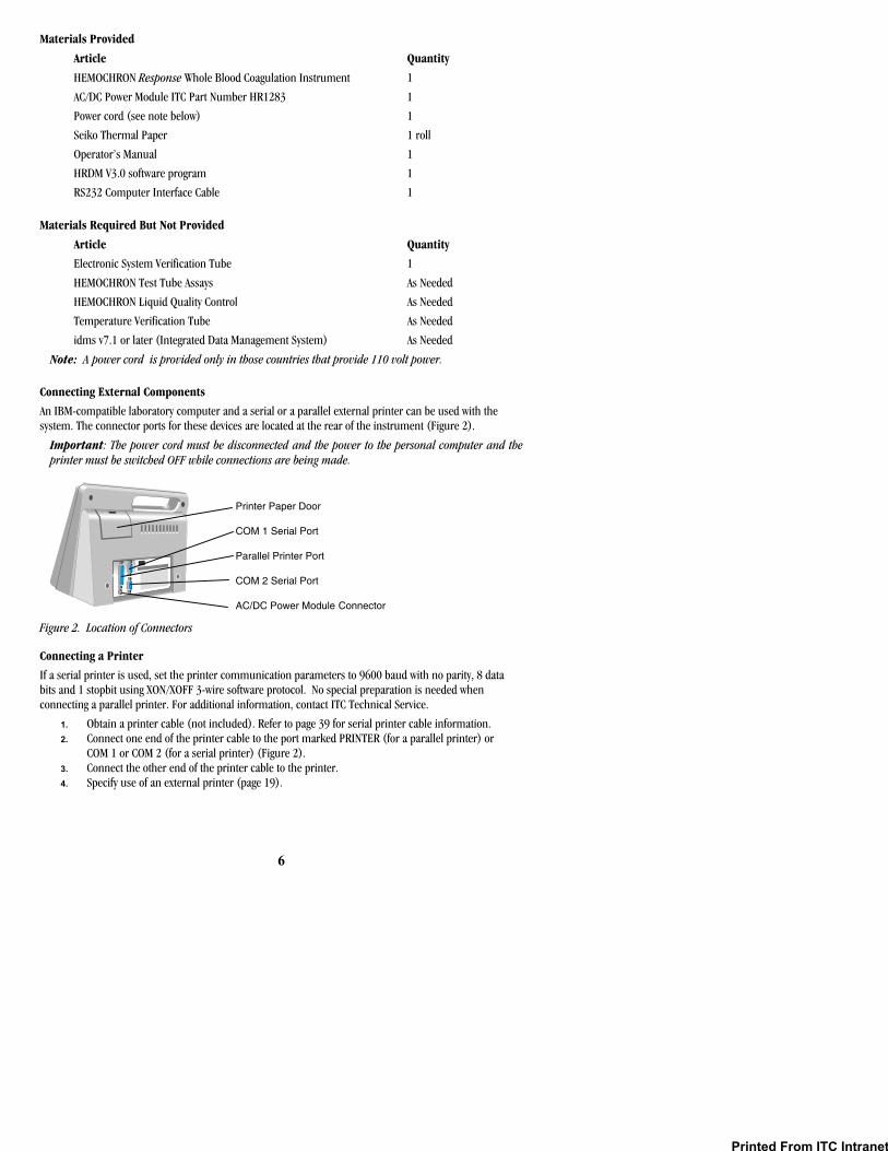
An IBM-compatible laboratory computer and a serial or a parallel external printer can be used with the system. The connector ports for these devices are located at the rear of the instrument (Figure 2).
Important: The power cord must be disconnected and the power to the personal computer and the printer must be switched OFF while connections are being made.
Figure 2. Location of Connectors
Connecting a Printer
If a serial printer is used, set the printer communication parameters to 9600 baud with no parity, 8 data bits and 1 stopbit using XON/XOFF 3-wire software protocol. No special preparation is needed when connecting a parallel printer. For additional information, contact ITC Technical Service.
1. Obtain a printer cable (not included). Refer to page 39 for serial printer cable information. 2. Connect one end of the printer cable to the port marked PRINTER (for a parallel printer) or
COM 1 or COM 2 (for a serial printer) (Figure 2). 3. Connect the other end of the printer cable to the printer. 4. Specify use of an external printer (page 19).
Article Quantity
HEMOCHRON Response Whole Blood Coagulation Instrument 1
AC/DC Power Module ITC Part Number HR1283 1
Power cord (see note below) 1
Seiko Thermal Paper 1 roll
Operator’s Manual 1
HRDM V3.0 software program 1
Printer Paper Door
COM 1 Serial Port
Parallel Printer Port
COM 2 Serial Port
AC/DC Power Module Connector
Printed From ITC Intranet

7
Connecting a Personal Computer
The system can be connected to a personal computer using a standard NULL modem cable.
1. Obtain an RS232 cable (provided). Refer to page 39 for cable information. 2. Connect one end of the cable to the port marked COM 1 or COM 2 (Figure 2). 3. Connect the other end of the cable to an unused serial communication port on the computer.
Note the location (COM 1 or COM 2) of the port. 4. Set the COM port location as described on page 19.
Connecting a Bar Code Reader
A bar code reader can be attached to the HEMOCHRON Response for use in entering parameters such as OID and PID.
Note: Refer to page 39 for information on connecting the bar code reader and configuring the cable.
1. Connect the cable to the port selected in Set Output Options. 2. Set the COM port location as described on page 19.
Note: Only one COM port can be designated for a bar code reader at a time.
Charging the Battery
The battery of the system must be charged before the system can be used.
1. Plug the AC/DC Power Module into an electrical service outlet. Caution: Ensure that the input voltage requirements of the AC/DC Power Module match the voltage used in the laboratory.
2. Connect the AC/DC Power Module cord to the Power connector (Figure 2). 3. Allow the battery to charge for at least 16 hours.
Note: The AC/DC Power Module can remain connected indefinitely.
Low Battery Warning
The battery supplies power whenever the system is operated without the AC/DC Power Module. The system will operate for at least eight hours on a fully charged battery.
The amount of charge remaining is displayed, either as a numerical percentage or as a bar indicator (page 19) whenever the battery is used to operate the system. CHARGE BATTERY is displayed and the battery power display blinks when the battery power drops to 30 percent of full charge. The system can still be used until the battery power drops to 10 percent.
BATTERY TOO WEAK TO RUN TESTS is displayed when the battery power drops to 10 percent of full charge. SHUTDOWN IN XX SECONDS is displayed beginning 30 seconds before the system is automatically shut down.
Loading Paper in the Internal Printer
Printer paper must be loaded if the internal printer is to be used.
Important: Red lines on the sides of the paper indicate an empty roll. As soon as red lines appear, replace the roll with a new roll to avoid a paper jam.
1. Open the paper door and remove the spent roll. 2. Unroll the end of the new roll and cut off the corners to form a pointed end. 3. Holding the roll of paper so the pointed end is pointing away from you and up, thread the pointed
end into the paper slot until it appears at the top of the printer. 4. Grasp the pointed end pull it upwards. 5. Place the new roll into the printer and close the door.
Printed From ITC Intranet
8
Prewarming
The test wells can be prewarmed to 37 °C ±1.0 °C on command. On completion, 3 short beeps are emitted.
Note: Refer to assay package inserts for prewarming requirements.
Automatic Shutdown
When operating from the battery, the system shuts down automatically after 15 minutes of inactivity. This 15-minute interval cannot be changed. When operating from the AC/DC Power Module, the system automatically shuts down after an interval of inactivity defined by the supervisor.
Note: The factory default setting is 60 minutes.
All stored data is retained after an automatic shutdown.
Test Termination
A test is terminated if clot formation is not detected within 1,500 seconds after starting the test. A FAULT >1500 message is then displayed and stored in the database, indicating the test result is outside of the specified range.
Note: Results that are greater than the specified time are beyond the sensitivity range of the test. They should be repeated immediately and, if confirmed, reported as greater than the maximum time.
A test is automatically terminated if after pressing START a test tube is not inserted into that well within 60 seconds or if a stable magnet is not detected in that well within 75 seconds.
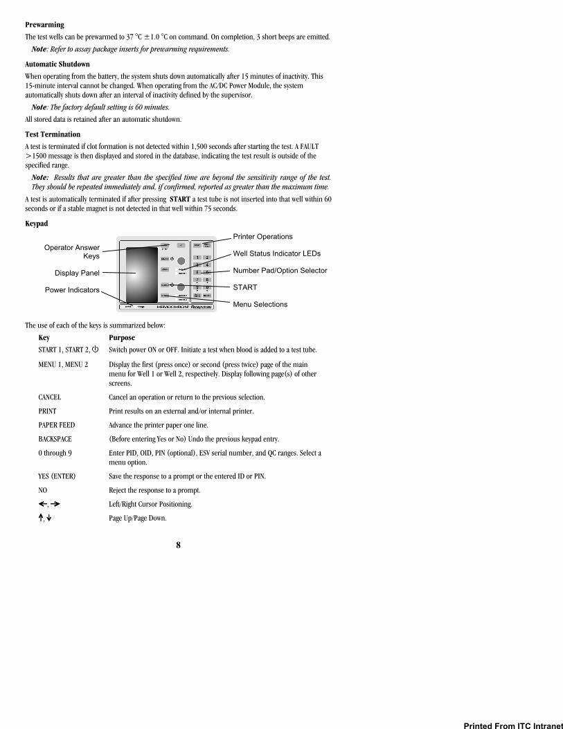
Keypad
The use of each of the keys is summarized below:
Key Purpose
START 1, START 2, Switch power ON or OFF. Initiate a test when blood is added to a test tube.
MENU 1, MENU 2 Display the first (press once) or second (press twice) page of the main menu for Well 1 or Well 2, respectively. Display following page(s) of other screens.
CANCEL Cancel an operation or return to the previous selection.
PRINT Print results on an external and/or internal printer.
PAPER FEED Advance the printer paper one line.
BACKSPACE (Before entering Yes or No) Undo the previous keypad entry.
0 through 9 Enter PID, OID, PIN (optional), ESV serial number, and QC ranges. Select a menu option.
YES (ENTER) Save the response to a prompt or the entered ID or PIN.
NO Reject the response to a prompt.
, Left/Right Cursor Positioning.
, Page Up/Page Down.
Printer Operations Well Status Indicator LEDs Number Pad/Option Selector START Menu Selections
Operator AnswerKeys
Display Panel
Power Indicators
Printed From ITC Intranet

9
Display Panel Operations such as running a test and prewarming a well can be carried out simultaneously on both wells. However, commands, prompts, and test results that appear on the display panel apply to a single well. The well for which commands are displayed is designated by the position of the divider bar (the bar in which the time and remaining battery power are displayed) (Figure 3).
Figure 3. Display Panel
Commands and results for Well 1 are shown in the upper portion of the of the display panel, while commands and results for Well 2 are shown in the lower portion of the display panel (Figure 4).
Figure 4. Display of Commands
Press the appropriate MENU key to display a menu of commands for the corresponding well. Press the appropriate START key to start a test in the corresponding well. During testing and other operations, the divider bar indicates the well for which results or prompts are displayed (Figure 5).
Figure 5. Display of Results
Well 1Commands
Divider Bar
Divider Bar
Well 2Commands
Well 1 TestResults and
Prompts
Divider Bar
Divider Bar
Well 2 TestResults and
Prompts
Divider Bar
Arrows
Printed From ITC Intranet

10
The arrows designate the operation that will be halted if the CANCEL key is pressed. If an operation is canceled, the arrows will point to the next operation that can be canceled. If an operation cannot be canceled, arrows are not displayed.
Note: Pressing CANCEL shuts down a test, removes any related menus, sets the assay to the default assay, sets the record type to Patient, resets the OID or PIN and resets all lockouts.
Operation for either well can be stopped by ensuring that the arrows point to the display for that well and then pressing CANCEL.
Note: For example, if PT FWB is run in Well 1, information and results for the test are displayed on the upper portion of the display panel. Then, if another test is run in Well 2 while PT FWB is being run in Well 1, the display will show information and results for the second test on the lower portion of the display panel and arrows will indicate that the Well 2 operation will be stopped if CANCEL is pressed.
Note: During operation, press 1 or 2 to point the arrows towards the display for the corresponding well. During display of a menu, press a MENU key to display the menu for the corresponding well.
When using the AC/DC Power Module, the display is fully illuminated for the flashlight time specified by the operator. While running on the battery, the display dims after one minute. Pressing any key or test completion restores the display. When the battery is used, the percentage of battery power remaining is displayed either as a numerical percentage or as a bar indicator, as specified during setting of Output Options.
Indicator LEDs
The indicator LEDs are illuminated as described below:
LED Purpose
Power The system is turned ON.
Charge The AC/DC Power Module is used.
Detect 1/2 The test tube magnet is in the detector zone in Well 1/Well 2.
Heater 1/2 Heat is applied to Well 1/Well 2.
Menus
Note: Some commands (such as Prewarm Well) are specific to a single well and the corresponding key (MENU 1 or MENU 2) must be used. Other commands (such as System OFF) apply to the entire system and either key can be used.
Whenever a menu has more than one page of commands, the page symbol is displayed on the right side of the display. Display subsequent pages by pressing a MENU key. Alternately, press the 0 key to display the next page of commands or press the 9 key to display the previous page of commands.
Press a MENU key once to display the first page of the main menu (Figure 6):
Figure 6. First Page of the Main Menu
Printed From ITC Intranet
11
Select a command by pressing the corresponding numeral key while the command is displayed. For example, if a PID or OID/PIN is to be entered using the ID Selects command, press 1.
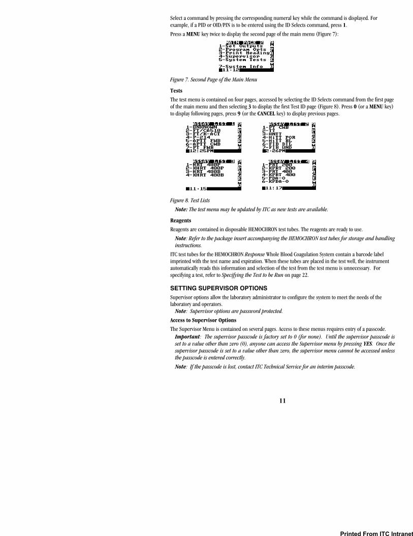
Press a MENU key twice to display the second page of the main menu (Figure 7):
Figure 7. Second Page of the Main Menu
Tests
The test menu is contained on four pages, accessed by selecting the ID Selects command from the first page of the main menu and then selecting 3 to display the first Test ID page (Figure 8). Press 0 (or a MENU key) to display following pages, press 9 (or the CANCEL key) to display previous pages.
Figure 8. Test Lists
Note: The test menu may be updated by ITC as new tests are available.
Reagents
Reagents are contained in disposable HEMOCHRON test tubes. The reagents are ready to use.
Note: Refer to the package insert accompanying the HEMOCHRON test tubes for storage and handling instructions.
ITC test tubes for the HEMOCHRON Response Whole Blood Coagulation System contain a barcode label imprinted with the test name and expiration. When these tubes are placed in the test well, the instrument automatically reads this information and selection of the test from the test menu is unnecessary. For specifying a test, refer to Specifying the Test to be Run on page 22.
SETTING SUPERVISOR OPTIONS Supervisor options allow the laboratory administrator to configure the system to meet the needs of the laboratory and operators.
Note: Supervisor options are password protected.
Access to Supervisor Options
The Supervisor Menu is contained on several pages. Access to these menus requires entry of a passcode. Important: The supervisor passcode is factory set to 0 (for none). Until the supervisor passcode is set to a value other than zero (0), anyone can access the Supervisor menu by pressing YES. Once the supervisor passcode is set to a value other than zero, the supervisor menu cannot be accessed unless the passcode is entered correctly.
Note: If the passcode is lost, contact ITC Technical Service for an interim passcode.
Printed From ITC Intranet
12
To Display the Supervisor Menu: 1. Display the second page of the main menu. 2. Press 4 to display the Enter Passcode prompt. Enter the passcode. 3. Press YES to accept. The first page of the Supervisor menu is displayed. 4. Press MENU once or twice to display the second or third page of the Supervisor menu.
Note: The next or previous pages can also be displayed by pressing 0 or 9.
Setting the Time
The time that a test is performed is automatically recorded with the test result. Specify the time format prior to setting the time.
Note: Use a 24-hour or a 12-hour format. 1. Display the first page of the Supervisor menu. 2. Press 1. The Time/Date Setup menu is displayed. 3. Press 1. The Set Time prompt is displayed with the current time. 4. Enter the correct time using the numeral keys. 5. Press YES to save the new time.
Note: Pressing CANCEL cancels the procedure without saving the new time.
Setting the Date
The date the test is performed is automatically recorded with the test result.
1. Display the first page of the Supervisor menu. 2. Press 1. The Time/Date Setup menu is displayed. 3. Press 2. The Set Date prompt is displayed with the current date. 4. Enter the correct date using the numeral keys.
Note: The date can be entered using either a MON/DAY/YEAR or a YEAR/MON/DAY format. 5. Press YES to save the new date.
Note: Pressing CANCEL cancels the procedure without saving the new date.
Specifying the Time Format
The time can be entered and reported in either 24-hour format or 12-hour format.
1. Display the first page of the Supervisor menu. 2. Press 1. The Time/Date Setup menu is displayed. 3. Press 3. The time formats are displayed. 4. Press 1 to select the 12-hour clock mode. Press 2 to select the 24-hour clock mode. 5. Press YES or CANCEL.
Note: The arrow points to the currently selected option.
Specifying the Reported Date Format
The date can be reported in either MON/DAY/YEAR format or YEAR/MON/DAY format. To Change the Date Format:
1. Display the first page of the Supervisor menu. 2. Press 1. The Time/Date Setup menu is displayed. 3. Press 4. The date formats are displayed. 4. Press 1 to select the MON/DAY/YEAR mode. Press 2 to select the YEAR/MON/DAY mode. 5. Press YES or CANCEL.
Note: The arrow points to the currently selected option.
Printed From ITC Intranet
13
Displaying the Clock
The time can be displayed on the separator bar of the display panel.
1. Display the first page of the Supervisor menu. 2. Press 5 to display the Clock line. ON will be displayed after the Clock line.
Note: Displaying the clock operates as a toggle. If clock is already specified (displayed as ON), it can be canceled by pressing 5 again to display OFF.
Specifying Auto Shutdown Time
When operated with the AC/DC Power Module, the maximum time that the instrument can remain inactive before it automatically shuts down can be specified; this is preset at the factory to 60 minutes.
Note: When the instrument is operated from the battery, it shuts down automatically after 15 minutes, regardless of the specified Auto Shutdown time.
1. Display the first page of the Supervisor menu. 2. Press 6 to display the Enter Auto Shutdown Time prompt. 3. Enter the time (1 to 999 minutes) that the instrument can remain inactive before it will
automatically shutdown. Or, enter 0 to disable this feature. 4. Press YES to save the new time interval and display the first page of the Supervisor menu.
Specifying the Default Assay
The instrument will automatically identify a test as the default assay if a test has not been otherwise specified by the barcode on the test tube or by the operator. If an illegible barcode is identified, the test will be labeled “Unknown”.
1. Display the first page of the Supervisor menu. 2. Press 7. The first page of the Assay List is displayed. 3. Select the desired test. If needed, press 9 or 0 to display another page of the Assay List. 4. Press YES to save the new default assay. 5. The Default Assay will appear on the display panel for each well until another test is selected.
Requiring Entry of PID
Entry of a PID can be required before a test can be run.
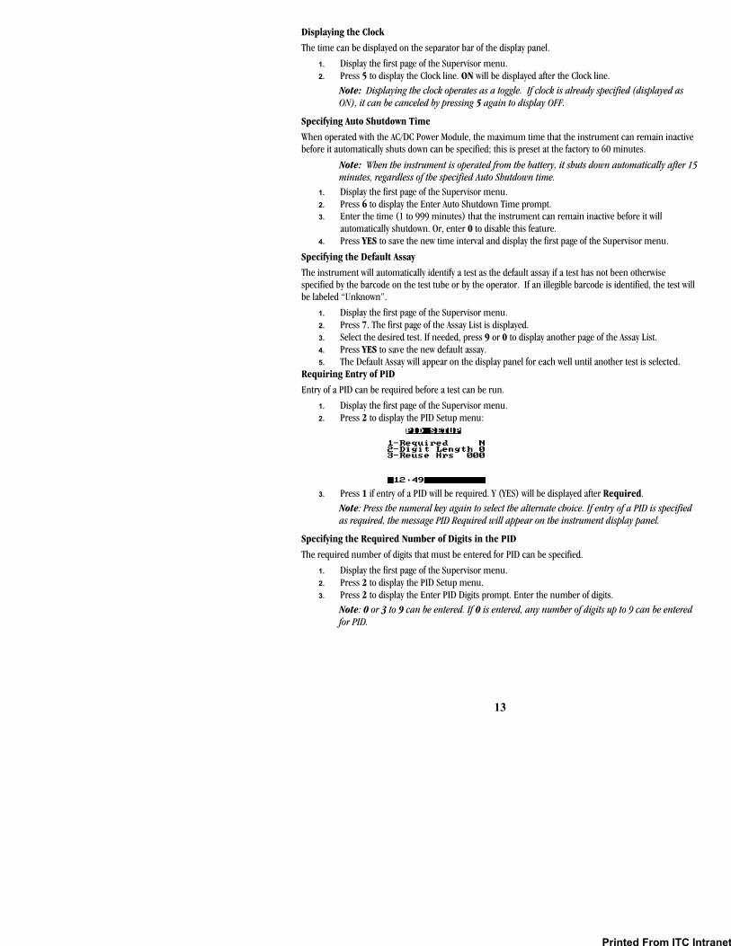
1. Display the first page of the Supervisor menu. 2. Press 2 to display the PID Setup menu:
3. Press 1 if entry of a PID will be required. Y (YES) will be displayed after Required.
Note: Press the numeral key again to select the alternate choice. If entry of a PID is specified as required, the message PID Required will appear on the instrument display panel.
Specifying the Required Number of Digits in the PID
The required number of digits that must be entered for PID can be specified.
1. Display the first page of the Supervisor menu. 2. Press 2 to display the PID Setup menu. 3. Press 2 to display the Enter PID Digits prompt. Enter the number of digits.
Note: 0 or 3 to 9 can be entered. If 0 is entered, any number of digits up to 9 can be entered for PID.
Printed From ITC Intranet
14
Specifying the Length of Time a PID will be Reused
After a PID is entered, it can be displayed as a default entry for a specified number of hours.
1. Display the first page of the Supervisor menu. 2. Press 2 to display the PID Setup menu. 3. Press 3 to display the Enter Reuse Hrs prompt. Enter the number of hours.
Note: 0 to 240 can be entered. If 0 is entered, the entered PID will not be reused.
Requiring Entry of an OID or PIN
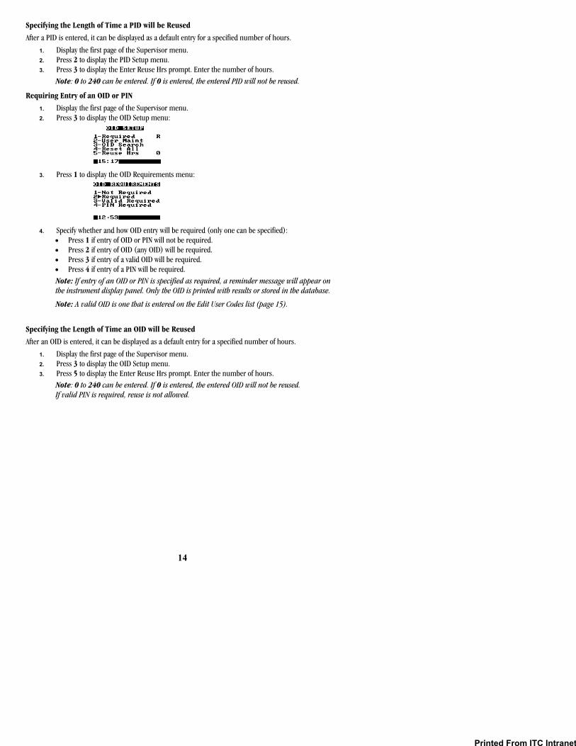
1. Display the first page of the Supervisor menu. 2. Press 3 to display the OID Setup menu:
3. Press 1 to display the OID Requirements menu:
4. Specify whether and how OID entry will be required (only one can be specified): • Press 1 if entry of OID or PIN will not be required. • Press 2 if entry of OID (any OID) will be required. • Press 3 if entry of a valid OID will be required. • Press 4 if entry of a PIN will be required. Note: If entry of an OID or PIN is specified as required, a reminder message will appear on the instrument display panel. Only the OID is printed with results or stored in the database.
Note: A valid OID is one that is entered on the Edit User Codes list (page 15).
Specifying the Length of Time an OID will be Reused
After an OID is entered, it can be displayed as a default entry for a specified number of hours.
1. Display the first page of the Supervisor menu. 2. Press 3 to display the OID Setup menu. 3. Press 5 to display the Enter Reuse Hrs prompt. Enter the number of hours.
Note: 0 to 240 can be entered. If 0 is entered, the entered OID will not be reused. If valid PIN is required, reuse is not allowed.
Printed From ITC Intranet
15
Specifying OID, PIN, and Test Permissions for an Operator
Note: HRDM V. 3.0 or higher software can be used to manage operator tables.
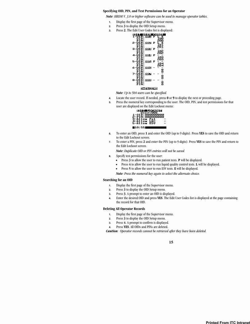
1. Display the first page of the Supervisor menu. 2. Press 3 to display the OID Setup menu. 3. Press 2. The Edit User Codes list is displayed:
Note: Up to 504 users can be specified.
4. Locate the user record. If needed, press 0 or 9 to display the next or preceding page. 5. Press the numeral key corresponding to the user. The OID, PIN, and test permissions for that
user are displayed on the Edit Lockout menu:
6. To enter an OID, press 1 and enter the OID (up to 9 digits). Press YES to save the OID and return to the Edit Lockout screen.
7. To enter a PIN, press 2 and enter the PIN (up to 9 digits). Press YES to save the PIN and return to the Edit Lockout screen. Note: Duplicate OID or PIN entries will not be saved.
8. Specify test permissions for the user: • Press 3 to allow the user to run patient tests. P will be displayed. • Press 4 to allow the user to run liquid quality control tests. L will be displayed. • Press 5 to allow the user to run ESV tests. E will be displayed. Note: Press the numeral key again to select the alternate choice.
Searching for an OID
1. Display the first page of the Supervisor menu. 2. Press 3 to display the OID Setup menu. 3. Press 3. A prompt to enter an OID is displayed. 4. Enter the desired OID and press YES. The Edit User Codes list is displayed at the page containing
the record for that OID.
Deleting All Operator Records
1. Display the first page of the Supervisor menu. 2. Press 3 to display the OID Setup menu. 3. Press 4. A prompt to confirm is displayed. 4. Press YES. All OIDs and PINs are deleted.
Caution: Operator records cannot be retrieved after they have been deleted.
Printed From ITC Intranet
16
Specifying QC Lockouts
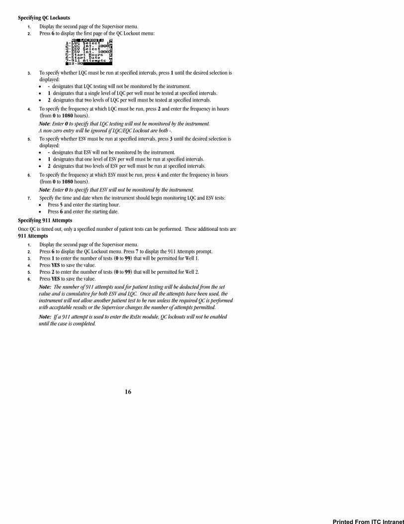
1. Display the second page of the Supervisor menu. 2. Press 6 to display the first page of the QC Lockout menu:
3. To specify whether LQC must be run at specified intervals, press 1 until the desired selection is displayed: • - designates that LQC testing will not be monitored by the instrument. • 1 designates that a single level of LQC per well must be tested at specified intervals. • 2 designates that two levels of LQC per well must be tested at specified intervals.
4. To specify the frequency at which LQC must be run, press 2 and enter the frequency in hours (from 0 to 1080 hours). Note: Enter 0 to specify that LQC testing will not be monitored by the instrument. A non-zero entry will be ignored if LQC/EQC Lockout are both -.
5. To specify whether ESV must be run at specified intervals, press 3 until the desired selection is displayed: • - designates that ESV will not be monitored by the instrument. • 1 designates that one level of ESV per well must be run at specified intervals. • 2 designates that two levels of ESV per well must be run at specified intervals.
6. To specify the frequency at which ESV must be run, press 4 and enter the frequency in hours (from 0 to 1080 hours). Note: Enter 0 to specify that ESV will not be monitored by the instrument.
7. Specify the time and date when the instrument should begin monitoring LQC and ESV tests: • Press 5 and enter the starting hour. • Press 6 and enter the starting date.
Specifying 911 Attempts
Once QC is timed out, only a specified number of patient tests can be performed. These additional tests are 911 Attempts
1. Display the second page of the Supervisor menu. 2. Press 6 to display the QC Lockout menu. Press 7 to display the 911 Attempts prompt. 3. Press 1 to enter the number of tests (0 to 99) that will be permitted for Well 1. 4. Press YES to save the value. 5. Press 2 to enter the number of tests (0 to 99) that will be permitted for Well 2. 6. Press YES to save the value.
Note: The number of 911 attempts used for patient testing will be deducted from the set value and is cumulative for both ESV and LQC. Once all the attempts have been used, the instrument will not allow another patient test to be run unless the required QC is performed with acceptable results or the Supervisor changes the number of attempts permitted.
Note: If a 911 attempt is used to enter the RxDx module, QC lockouts will not be enabled until the case is completed.
Printed From ITC Intranet

17
Suppressing Results Display During a QC Test
Display of the clotting time during a QC test (on the screen, printed result, and in the database) can be suppressed.
1. Display the second page of the Supervisor menu. 2. Press 6 to display the QC Lockout menu. Press MENU or 0 to display the second page. 3. Press 1 to hide the results. Y is displayed.
Note: Press the numeral key again to select the alternate choice.
Note: If QC Hide is enabled, a QC test result will be displayed as Pass/Fail without a clotting time. The actual test record with all results is stored and can be downloaded or accessed by turning off QC Hide.
Defining a User Note
Up to nine customized notes of up to 16 characters in length can be defined. Up to two of these notes can be selected and appended to a test record by the operator when the test is run.
Note: HRDM V. 3.0 or higher software can be used to enter notes on a PC and transfer them to the instrument.
1. Display the second page of the Supervisor menu. 2. Press 7. In response to the prompt, enter the number of the note (1 to 9) to be created or
changed. 3. The User Note screen is displayed, with the cursor positioned on the first character of the note
and the selection block positioned at the space:
4. Press 8 to move the selection block right one character, press 7 to move the selection block left one character, press 9 to move the selection block up one line, or press 0 to move the selection block down one line.
5. When the selection block is on the correct character, press YES to enter the selected character and move the cursor to the position for the next character.
6. Repeat Steps 4 and 5 for each character to be entered in the note. Note: The note can be edited after characters have been entered. Press NO to move the cursor one space to the right; press BACKSPACE to move the cursor one space to the left. When the cursor is at the desired position, press 2 to overwrite a character with a space, press 3 to insert a space before the selected character, or press 4 to delete the character at the selected position. Press 1 to clear the note.
7. When the note is completed, press CANCEL to save the note and exit the screen.
CursorSelection Block
Printed From ITC Intranet
18
Downloading Records
Patient and QC records can be downloaded to a personal computer from the system. ITC data management software programs can be installed on the personal computer to which the records are being downloaded to provide the reporting functions.
1. Connect the COM 1 or the COM 2 port of the HEMOCHRON Response to the personal computer. 2. Using the corresponding MENU key (MENU 1 for the COM 1 port, MENU 2 for the COM 2 port)
display the second page of the Supervisor menu. 3. Press 4. COMMANDER HR is displayed. 4. Refer to the HEMOCHRON Data Manager (HRDM V. 3.0 or higher) for additional information.
Changing the Language
The language can be specified. Choices are English, German, Italian, Spanish, French and Portuguese.
1. Display the second page of the Supervisor menu. 2. Press 5 to display the Select Languages menu. 3. Press the numeral key that corresponds to the language to be used. 4. Press YES or CANCEL to return to the previous menus.
Specifying the Supervisor Passcode
The Supervisor passcode may be changed.
1. Display the first page of the Supervisor menu. 2. Press 4. The Supervisor Passcode prompt is displayed with the current passcode. 3. Enter the new passcode. 4. Press YES to save the new passcode and return to the first page of the Supervisor menu. 5. Press CANCEL to return to the previous menus without saving.
Erasing Results
Results must be periodically erased to prevent overwriting the database.
Caution: Results cannot be retrieved after they have been erased from the database. Do not erase results until they have been printed or transmitted to the laboratory computer.
1. Display the second page of the Supervisor menu. 2. Press 1 (for patient records) or 2 (for QC records) to erase the current records from the
database. 3. Press YES to erase the records or NO to abort.
Specifying the Baud Rate
The speed at which data is transmitted to an external source via the COM Ports can be specified.
1. Verify that the external source is properly connected to either the COM 1 or the COM 2 port of the HEMOCHRON Response.
2. Using the corresponding MENU key (MENU 1 for the COM 1 port, MENU 2 for the COM 2 port) display the second page of the Supervisor menu.
3. Press 3 to display the Baud Rate menu and select the corresponding numeral key. 4. Press YES to save and return to the Supervisor menu.
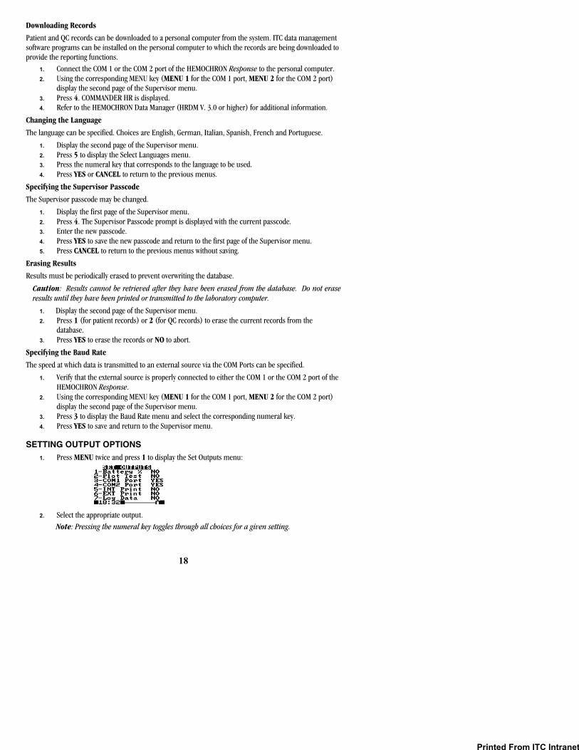
SETTING OUTPUT OPTIONS 1. Press MENU twice and press 1 to display the Set Outputs menu:
2. Select the appropriate output. Note: Pressing the numeral key toggles through all choices for a given setting.
Printed From ITC Intranet

19
Enabling Display of Remaining Battery Power
The amount of power remaining in the battery can be displayed either as a numerical percentage or as a bar indicator.
1. Press 1 in Set Outputs. YES is displayed after the Battery % line: 1 – Battery % - YES
2. Press 1 again to display a graph of remaining battery power. NO is displayed. Note: The battery power display disappears when the instrument is connected to an electrical outlet using the AC/DC Power Module.
Enabling Plotting of Test Data
Utilize this feature to indirectly observe the motion of the magnet during an assay. If plotting is enabled, two lines are displayed representing the magnet in the test tube. The position of the lines changes in accordance with the motion of the magnet until clot formation, when the lines cross.
1. Press 2 in Set Outputs. YES is displayed after the Plot Test line: 2 – Plot Test YES
Specifying the Device Connected to COM1 or COM2
If an external computer or a barcode reader is connected to the System, the COM port to which the device is connected must be specified. Only one COM port can be set to RDR at a given time.
1. Press 3 in Set Outputs to specify COM 1 or press 4 to specify COM 2. YES will be displayed, designating that an external computer is connected to the specified COM port:
3 – COM 1 Port YES
2. Press 3 or 4 a second time to designate that a barcode reader is connected to the specified COM port:
3 – COM 1 Port RDR
3. Press 3 or 4 a third time to designate that no device is connected to the specified COM port: 3 – COM 1 Port NO
Cycling through COM Port options resets the Baud Rate to 9600. Turning the device OFF or ON will set the Baud Rate to its initial setting.
Specifying Use of the Internal Printer
The internal printer is designed for printing single test results. The internal printer cannot be used for database printing. It can be deactivated to save power during battery operation.
1. Press 5 to select one of the three printer modes: 1 –No (No internal print) 2 –Yes (Permits printing of the last test result when the PRINT key is pressed) 3 –AUT (Automatically prints the test results when the test tube is removed)
Specifying Use of an External Printer
If the system is connected to an external parallel printer, this selection must be activated.
1. Press 6 in Set Outputs to specify connection to an external printer. YES will be displayed after the External Printer line:
6 – EXT Print YES Note: To print either database, an external printer must be used.
Note: The printer output is the IBM Layout (PC-8) standard.
Printed From ITC Intranet
20
Enabling Logging of Data
The data-logging feature is used to send raw data, obtained during an assay, to an external computer or printer. This feature is most useful for troubleshooting.
Note: An external printer or computer must be connected and enabled before the data-logging feature can be operated. Well 1 data are sent to COM 1 and Well 2 data are sent to COM 2.
1. Press 7 in Set Outputs to enable data logging. YES will be displayed after the Log Data line: 7 – Log Data YES
SETTING PROGRAM OPTIONS Program options allow the volume of audible signals and contrast, brightness, and illumination of the display to be adjusted. Settings range from 0% (lowest level) to 100% (highest level). Press 7 or 8 to increase or decrease the level by five percent. Press 9 or 0 to increase or decrease the level by one percent. Pressing and holding a key for more than one second causes it to auto-repeat.
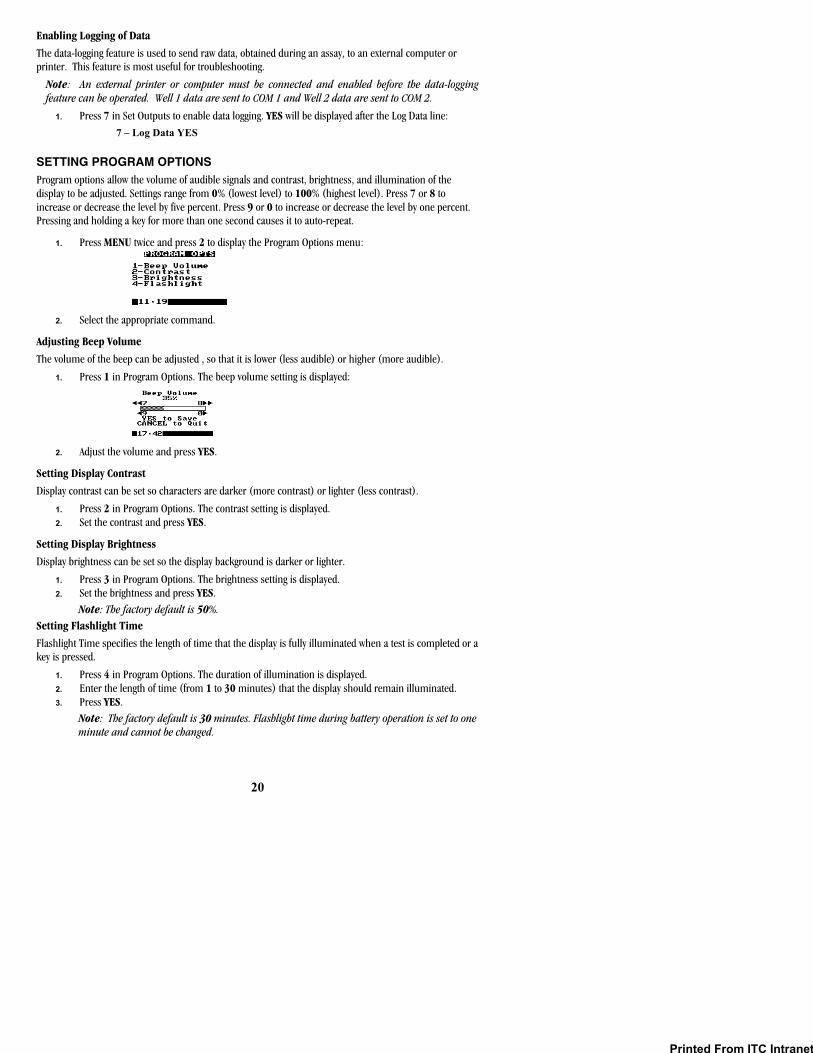
1. Press MENU twice and press 2 to display the Program Options menu:
2. Select the appropriate command.
Adjusting Beep Volume
The volume of the beep can be adjusted , so that it is lower (less audible) or higher (more audible).
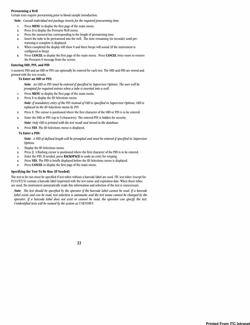
1. Press 1 in Program Options. The beep volume setting is displayed:
2. Adjust the volume and press YES.
Setting Display Contrast
Display contrast can be set so characters are darker (more contrast) or lighter (less contrast).
1. Press 2 in Program Options. The contrast setting is displayed. 2. Set the contrast and press YES.
Setting Display Brightness
Display brightness can be set so the display background is darker or lighter.
1. Press 3 in Program Options. The brightness setting is displayed. 2. Set the brightness and press YES.
Note: The factory default is 50%. Setting Flashlight Time
Flashlight Time specifies the length of time that the display is fully illuminated when a test is completed or a key is pressed.
1. Press 4 in Program Options. The duration of illumination is displayed. 2. Enter the length of time (from 1 to 30 minutes) that the display should remain illuminated. 3. Press YES.
Note: The factory default is 30 minutes. Flashlight time during battery operation is set to one minute and cannot be changed.
Printed From ITC Intranet

21
CUSTOMIZING THE PRINTED HEADING The heading at the top of each printout can be customized.
1. Press MENU twice and press 3 to display the Print Heading screen. The cursor is positioned on the first character of the heading and the selection block is positioned at the space:
2. Press 8 to move the selection block right one character, press 7 to move the selection block left one character, press 9 to move the selection block up one line, or press 0 to move the selection block down one line.
3. When the selection block is on the correct character, press YES to enter the selected character and move the cursor to the position for the next character.
4. Repeat Steps 2 and 3 for each character to be entered in the heading. Note: The heading can be edited after characters have been entered. Press NO to move the cursor one space to the right; press BACKSPACE to move the cursor one space to the left. When the cursor is at the desired position, press 2 to overwrite a character with a space, press 3 to insert a space before the selected character, or press 4 to delete the character at the selected position. Press 1 to clear the heading.
5. When the heading is completed, press CANCEL to save the heading and exit the screen.
OPERATION Tests can be run on the system any time after the battery has been charged. It is recommended, however, that the correct time and date are entered and configuration preferences are selected before tests are run.
Note: Refer to Setting Output Options, Setting Program Options, Customizing the Printed Heading and Setting Supervisor Options for instructions to enter the correct date and time and to configure the instrument.
Starting the Instrument
Press either START key. Self-test results are briefly displayed.
Note: OK is replaced by FAIL if a self-test fails. An alphanumeric code may also be displayed with the FAIL. The system will not operate on any FAIL condition except for PRINTER, COM1, COM2 or LPT1. Consult Troubleshooting if the self-tests do not pass or an error message is displayed.
After the self-test results are displayed, the instrument signals it is ready for operation by displaying operator instructions.
CursorSelection Block
Printed From ITC Intranet
22
Prewarming a Well Certain tests require prewarming prior to blood sample introduction.
Note: Consult individual test package inserts for the required prewarming time.
1. Press MENU to display the first page of the main menu. 2. Press 3 to display the Prewarm Well menu. 3. Press the numeral key corresponding to the length of prewarming time. 4. Insert the tube to be prewarmed into the well. The time remaining (in seconds) until pre-
warming is complete is displayed. 5. When completed the display will show 0 and three beeps will sound (if the instrument is
configured to beep). 6. Press CANCEL to display the first page of the main menu. Press CANCEL twice more to remove
the Prewarm 0 message from the screen.
Entering OID, PIN, and PID
A numeric PID and an OID or PIN can optionally be entered for each test. The OID and PID are stored and printed with the test results.
To Enter an OID or PIN:
Note: An OID or PIN must be entered if specified in Supervisor Options. The user will be prompted for required entries when a tube is inserted into a well.
1. Press MENU to display the first page of the main menu. 2. Press 1 to display the ID Selections menu.
Note: If mandatory entry of the PIN instead of OID is specified in Supervisor Options, OID is replaced in the ID Selections menu by PIN.
3. Press 1. The cursor is positioned where the first character of the OID or PIN is to be entered.
4. Enter the OID or PIN (up to 9 characters). The entered PIN is hidden for security. Note: Only OID is printed with the test result and stored in the database.
5. Press YES. The ID Selections menu is displayed.
To Enter a PID:
Note: A PID of defined length will be prompted and must be entered if specified in Supervisor Options.
1. Display the ID Selections menu. 2. Press 2. A flashing cursor is positioned where the first character of the PID is to be entered. 3. Enter the PID. If needed, press BACKSPACE to undo an entry for retyping. 4. Press YES. The PID is briefly displayed before the ID Selections menu is displayed. 5. Press CANCEL to display the first page of the main menu.
Specifying the Test To Be Run (If Needed)
The test to be run must be specified if test tubes without a barcode label are used. ITC test tubes (except for P214/P215) contain a barcode label imprinted with the test name and expiration date. When these tubes are used, the instrument automatically reads this information and selection of the test is unnecessary.
Note: The test should be specified by the operator if the barcode label cannot be read. If a barcode label exists and can be read, test selection is automatic and the test name cannot be changed by the operator. If a barcode label does not exist or cannot be read, the operator can specify the test. Unidentified tests will be named by the system as UNKNOWN.
Printed From ITC Intranet

23
To Specify the Test: 1. Display the ID Selections menu. Press 3 to display the first page of tests. 2. If the test is on the first list, select the test by pressing the corresponding numeral key. An arrow
will be displayed after the number of the selected test. 3. If the test is not displayed on the first page, display subsequent lists by pressing the MENU key
until the test is displayed. Then select the test by pressing the corresponding numeral key. 4. Press YES to save the test.
Note: Test selection is specific to a single well. Use MENU 1 or MENU 2 as appropriate. After the fibrinogen test is selected (by barcode or by manual entry), a prompt for entry of the PPID code will be displayed. The PPID code is found in the package insert that accompanies the fibrinogen test tubes.
To Display the RxDx menu: Note: The RxDx module is an additional feature of the Response system. Information can be requested from your local HEMOCHRON representative or ITC Customer Service on how the RxDx module can be activated.
1. Display the ID Selections menu.
2. Press 4 to display the RxDx menu. Refer to the HEMOCHRON Response RxDx Analysis Module Operator’s Manual for further instructions.
Designating an LQC
Important: A sample is designated as a patient sample by default. If an LQC is being run, it must be identified as such. Failure to select a QC tag for an LQC will result in storage of the result in the patient database.
Note: Refer to page 28 for procedure details.
Designating an ESV
Note: Refer to page 27 for procedure details.
Designating a Patient Sample
If a patient sample is to be run instead, the sample type must first be changed.
1. Press MENU once to display the first page of the main menu. 2. Press 2. The QC Selections menu is displayed. 3. Press 5. A prompt will confirm a patient test is being run: Patient Test 4. Run the test as described below.
Specimen Collection
Collect blood specimens according to NCCLS document H21-2, entitled Collection, Transport and Processing of Blood Specimens for Coagulation Testing and General Performance of Coagulation Assays.
Important: Collect blood specimens in a manner that prevents contamination with tissue thromboplastin, indwelling intravenous (I.V.) solutions, or alcohol cleansing solution. Discard samples that are not properly collected or contain visible clots or debris. Use a 23 gauge or larger needle if a syringe is used for blood collection. If a sample is expelled through the same needle, do it slowly to prevent hemolysis. Consult the individual test package insert for additional information concerning specimen collection and storage.
Printed From ITC Intranet
24
Starting the Test
Consult the individual test package insert to determine the volume of sample and appropriate test procedure to use.
1. Dispense the sample into the test tube and simultaneously press the START key. A beep will signal the start of the test and timing of the test begins.
2. Mix the contents of the test tube. Note: A test is automatically terminated if a tube is not detected within 60 seconds after pressing START.
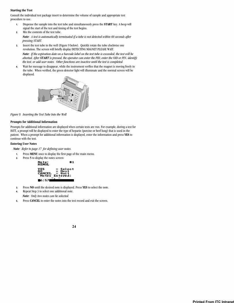
3. Insert the test tube in the well (Figure 9 below). Quickly rotate the tube clockwise one revolution. The screen will briefly display DETECTING MAGNET PLEASE WAIT. Note: If the expiration date on a barcode label on the test tube is exceeded, the test will be aborted. After START is pressed, the operator can enter the PID, enter the OID or PIN, identify the test, or add user notes. Other functions are inactive until the test is completed.
4. Wait for message to disappear, while the instrument verifies that the magnet is moving freely in the tube. When verified, the green detector light will illuminate and the normal screen will be displayed.
Figure 9. Inserting the Test Tube Into the Well
Prompts for Additional Information
Prompts for additional information are displayed when certain tests are run. For example, during a test for HiTT, a prompt will be displayed to enter the type of heparin (porcine or beef lung) that is used in the patient. When a prompt for additional information is displayed, enter the information and press YES to continue with the test.
Entering User Notes
Note: Refer to page 17 for defining user notes.
1. Press MENU once to display the first page of the main menu. 2. Press 5 to display the notes screen:
3. Press NO until the desired note is displayed. Press YES to select the note. 4. Repeat Step 3 to select one additional note.
Note: Only two notes can be selected. 5. Press CANCEL to enter the notes into the test record and exit the screen.
Printed From ITC Intranet
25
Aborting a Test
A test can be aborted once the timing has begun.
1. Press CANCEL. The instrument will display Hit YES to Abort. 2. Press YES to stop the test.
Note: The test can also be aborted by removing the tube after the test has been running for 15 seconds.
Results Display
While a test is running, the test name, temperature, PID (if entered), and the elapsed time after starting the test are displayed. If Test Plotting is enabled in configuration, a graphical representation of magnet movement will also appear on the display.
When clot formation is detected, the instrument beeps and the test name, clotting time (in seconds), and, where appropriate, plasma equivalent (in seconds) and/or INR results are displayed. The results will be displayed until the tube is removed from the well or until CANCEL or a START key is pressed.
Required Entry of OID or PIN
OID or PIN must be entered before running a test if specified in Supervisor Options. The instrument will begin running the test, but the results will not be displayed on the screen or stored in the database unless the OID or PIN is entered as specified.
A prompt will be displayed on the screen if entry of an OID or PIN is required.
To Enter a OID or PIN When Required: 1. Press START. The instrument will begin timing and prompt for entry of an OID or PIN. 2. Enter the OID or PIN and press YES. The test proceeds.
Note: An information message is displayed and the test is not completed if an OID or PIN is not entered as required.
Required Entry of PID
PID must be entered before running a test if specified in Supervisor Options (page 13). The instrument will begin running the test, but the results will not be displayed on the screen or stored in the database unless the PID is entered as specified.
A prompt will be displayed on the screen if entry of a PID is required.
To Enter a PID When Required: 1. Press START. The instrument will begin timing and prompt for entry of a PID. 2. Enter the PID and press YES. The test proceeds.
Note: An information message is displayed and the test is not completed if the entered PID does not contain the required number of digits (if specified in Supervisor Options).
Printing of Results
The date and time of the test, PID, OID, clotting time (in seconds), plasma equivalent, and INR results can be automatically printed when the test is completed.
Note: Results can also be printed at an external printer.
The results printing mode is selected during configuration of the system (page 19).
Note: An asterisk after the test name denotes that the test name was selected by the operator instead of being read by the barcode reader. A dollar sign ($) before a test result denotes that a patient test was run while QC was required.
Re-reading the Barcode
If a barcoded tube was used but the barcode was not successfully read at the beginning of the test, the system will attempt to read the barcode again at the end of the test.
Printed From ITC Intranet

26
Storage of Results
Patient and quality control test results are automatically stored when the test is completed. The OID, PID or QC tag, and date and time each test was run are stored with the results for each test.
Instrument Shutdown
To shut down the system, press either START key and hold it down. Or, select 7 - System Off from the first page of the main menu.
When using external power, the instrument will automatically shut down after it has remained inactive for 60 minutes or for the auto shutdown time specified by the supervisor.
When using battery power, the instrument will automatically shut down after it has remained inactive for 15 minutes.
Printed From ITC Intranet
27
QUALITY CONTROL (QC) The Joint Commission on Accreditation of Healthcare Organizations (JCAHO) recommends that medical and laboratory instrumentation be enrolled in a quality assurance program adequate in maintaining accurate and reliable performance of the equipment. Complete records of such quality control must be kept.
Routine quality control testing should be part of a comprehensive quality assurance program. This testing should include:
• Testing system performance using Electronic System Verification tube or LQC. • Testing test tube reagents in accordance with the Package Insert for each assay, using two levels of
liquid controls.
Self-Check
The HEMOCHRON Response instrument performs a “self-check” every time it is activated and a test is performed. When a test is initiated by pressing START, system checks are automatically performed and include:
• Verification of adequate battery power to complete a 1500 second test. • Verification that a tube has been inserted and that the test well is functioning properly. If any
rotation or temperature parameters are not appropriate, the test is terminated and an error message is displayed.
• For barcoded tubes, the test type and expiration data are read. The test type will be displayed on the screen. If the expiration date has passed, the test is aborted and an error message displayed. Once a barcode is read, the user cannot change the test type.
• Verification that the test well is warmed to 37± 1.0 ºC. If this temperature is not achieved or is exceeded, an appropriate error message will be displayed and testing is prohibited.
• Verification that the internal timers function correctly for each test. If the system timer and assay timer disagree at the end of a test, a real-time clock error message is displayed and the test result is not reported.
Operator Access to QC Procedures
If desired, operation of the instrument and running of quality control procedures can be restricted to operators authorized by the supervisor (page 15). If an unauthorized operator attempts to run a QC procedure, the message “Unauthorized Operator” is displayed.
Note: If QC Hide is enabled (page 17), a QC test result will be displayed as Pass/Fail without a clotting time.
QC Intervals
If desired, the maximum allowable time between running ESV and/or LQC (the QC interval) can be specified (page 16). If the specified QC interval is exceeded, the instrument will not run additional tests until QC is performed and the results are acceptable.
QC Using ESV
The instrument should be tested at two levels once during any shift in which the instrument is utilized. An ESV tube can be used to provide a three-level electronic verification of instrument performance, or LQC products can be used.
Note: The ESV tube and HEMOCHRON LQC products are available from ITC.
To Use the ESV Tube: 1. Press a START key to begin a test on a well. A beep will signal the start of the test. At the same
time, press the 100 second button on the ESV tube. 2. Insert the ESV tube into the test well. 3. A prompt is displayed if entry of an OID or PIN is required. Enter your OID or PIN and press YES. 4. A prompt is displayed to enter the serial number of the ESV tube. The serial number of the last
ESV used is displayed. Note: If needed, enter the ESV serial number (up to 9 characters) located on the back of the ESV tube. Press BACKSPACE to undo an entry for retyping.
Printed From ITC Intranet
28
5. When the correct ESV serial number is displayed, press YES. 6. Upon completion of the test and removal of the ESV tube from the well, the result is stored in the
database. Compare the result with the number of seconds selected in the first step. 7. Repeat, using the 300 second or 500 second button for the first well. Then, repeat the entire test
on the second well. Results are acceptable if within 10 seconds of the selected times. Note: Contact ITC if the results are not within range. The ESV may be manually tagged if the barcode label is not read.
QC Using Liquid Controls
The instrument can also be tested at any time using LQC products.
Note: HEMOCHRON LQC products are available from ITC. Refer to the LQC package insert for procedural description.
To Run LQC: 1. Press MENU to display the first page of the main menu. 2. Press 2 to display the QC Selections menu.
Note: If the current operator is not allowed (see Supervisor Options) to run LQC, an information message is displayed and the operator cannot proceed.
3. Press 1 or 2, corresponding to whether a normal or abnormal control is being run. The QC menu for the selected control level is displayed.
4. Press 1. The current lower limit for the control range is displayed with the cursor positioned where the first character of the new lower limit is to be entered.
5. If needed, enter the new lower limit (up to 4 characters). If needed, press BACKSPACE to undo an entry for retyping.
6. Press YES. The prompt Lower Stored is briefly displayed with the new lower limit value. 7. Press 2. Repeat Steps 5 and 6 for the upper limit. 8. Press 3. Enter the lot number for the control. 9. Press YES to accept the new entries. 10. Press CANCEL to return to previous menus. 11. Perform the test.
Mandatory QC Testing
A time interval can be specified from 1 to 1080 hours before either LQC and/or ESV tests must be run. Specifying a time interval of zero disables this feature. If a time interval is specified for LQC and/or ESV testing, the instrument will remind the operator when LQC or ESV is due.
Note: The required interval between QC tests is specified using the QC Lockout menu. Refer to Setting Supervisor Options for details. If LQC and ESV testing intervals coincide, only performance of LQC will be required. Performance of ESV will not be required until the next interval.
When the specified time interval has expired, the instrument will lock and indicate which controls must be run.
Note: The instrument can be unlocked by an authorized operator for a specified number of additional tests if the 911 Attempts option is enabled using the QC Lockout menu (page 16).
Additional Method to Verify Instrument Temperature
A Quality Control temperature evaluation of the HEMOCHRON Response instrument is performed automatically each time a test is run (see the Self-Check section on page 27). However, for purposes of your QC program, it may be preferred to additionally perform a temperature QC evaluation using the ITC Temperature Verification Tube to verify that a temperature of 37 °C ±1.0 °C is maintained. The Temperature Verification Tube can be obtained from ITC.
Printed From ITC Intranet
29
911 Attempts
The instrument can be unlocked by an authorized operator for a specified number of additional patient tests after the maximum time between controls has been exceeded. This option is available if the 911 Attempts option is enabled (page 16).
Note: The number of 911 Attempts that can be used to override mandatory QC is specified during setting of Supervisory Options. A dollar sign ($) will be included on the result printout of any test run using the 911 Attempts option.
To Use 911 Attempts when QC is Timed Out: 1. Dispense the sample into the test tube and simultaneously press the START key. A beep signals
the start of the test, and the QC Selections menu is displayed. Note: If OID or PIN and/or PID options are enabled, other menus will be displayed prior to the QC Selections menu.
2. Select a patient test. The QC Overrides that remain are briefly displayed. Note: The message indicates the number of 911 attempts that will remain for the specified well once the test is completed. The clotting time is displayed on the screen.
3. Once all the 911 attempts are used, the instrument disallows patient tests. To allow access to the instrument, Quality Control must be successfully run or the supervisor must increase the allowable number of 911 attempts.
OPERATING PRECAUTIONS The AC/DC Power Module should be plugged into a standard AC outlet to charge the instrument when it is not in use.
DO NOT remove the AC/DC Power Module from the instrument by pulling on the cord. It is recommended that the AC/DC Power Module be unplugged from the AC outlet when it is not being used to charge the instrument.
DO NOT use tubes that are past their marked expiration date or which have been improperly stored.
DO NOT force a tube into the instrument. If resistance to insertion is encountered, gently remove the tube and examine the test well. Remove any obstruction before attempting further use of the instrument (see Maintenance on page 38).
DO NOT use excessive force in pressing the instrument keys.
DO NOT expose the instrument to extreme temperatures (above 37 °C).
DO NOT drop the instrument.
DO NOT remove stoppers to deliver a blood sample to the tube.
The HEMOCHRON Response instrument should only be used by healthcare professionals trained and certified in the use of the system and operated in accordance with facility policies and procedures.
All biohazard safety guidelines pertaining to the handling and disposal of human blood should be strictly adhered to when collecting and handing blood specimens and when operating the HEMOCHRON Response Whole Blood Coagulation System.
Used HEMOCHRON test tubes should be considered as potentially infectious. They should be handled according to individual institutional policies concerning the disposal of potentially infectious materials.
HEMOCHRON Response test results should always be scrutinized in light of a specific patient’s condition or anticoagulant therapy. Any test results exhibiting inconsistency with the patient’s clinical status should be repeated or supplemented with additional diagnostic tests.
LIMITATIONS Test results of the HEMOCHRON Response Whole Blood Coagulation System are affected by poor technique during blood collection and sample handling. The accuracy of the test is largely dependent upon the quality of the blood specimen. Refer to the individual assay package insert for specific limitations.
Printed From ITC Intranet

30
RESULTS MANAGEMENT Overview
Up to 600 patient test results and 300 quality control test results per test well are stored in the instrument database. In addition to test results, the date and time of each test, PID (if entered) or QC tag, and OID (if specified) are also stored.
The stored results can be grouped by type of result (patient or QC result), PID, or OID for display, review and printing. When printing test results, the results of the last test or the entire database of patient results or QC results can be printed.
Caution: Verify that any third-party connectivity software to be used is compatible with the software version of the HEMOCHRON Response instrument in use. Transferred data will be lost if third-party connectivity software is used with non-compatible versions of HEMOCHRON Response software.
Printing Results
Results of the last test or the entire database of patient results or QC results can be printed.
Note: An external printer or computer is required for database printing. Although the internal printer can be used to print results from the database, it is designed for single test result printing.
To Print Results: 1. Press the PRINT key. A menu of printer commands is displayed. 2. Press 1, 2 or 3 as appropriate. The selected results are printed.
Note: The date and time the test was run and the OID (if specified) are also printed for each test. For patient results, the PID (if entered) is also printed for each test.
3. If needed, press 4 to cancel printing of results.
Database Query
Database Query commands are used to:
• Determine the number of patient or QC results stored in the database for either well • Display the record for a particular test that was run • Search the database for records matching selected criteria
Caution: Results from the oldest test are overwritten if a test is run when the database for a well is full. Therefore, it is important to periodically check, print, archive and erase the database contents.
To Check the Database: 1. Display the first page of the main menu. 2. Press 4 to display the Database menu. Press 2 (for total patient records) or 4 (for total QC
records) to display the number of records currently stored in the database. 3. Press any key to display the Database menu again. 4. Press 5 to display the total number of records that are currently in both the patient and QC
databases for both wells. This information will be displayed for ten seconds before the Database menu is displayed again.
To Display a Particular Record: 1. Display the first page of the main menu. 2. Press 4 to display the Database menu. Press 1 (for a patient record) or 3 (for a QC record) to
display the number of records in the selected database. 3. Enter the number for the first record to be displayed and press YES. The specified record
number is displayed. 4. Press YES to display the specified record. Press 0 or 9 to display other records in ascending or
descending order. Press 8 to display the test status screen. Press CANCEL to return to previous menus.
Printed From ITC Intranet

31
To Search a Database: 1. Display the first page of the main menu. 2. Press 4 to display the Database menu. Press 1 (for a patient record) or 3 (for a QC record). The
number of records in the selected database is displayed. 3. Enter the number for the first record to be displayed and press YES. The specified record
number is displayed. 4. Press 1 to display search options. Press the number corresponding to a search category. 5. Enter the appropriate response to any prompts and press YES. 6. The most recent matching record is displayed. Press 0 or 9 to display other records in ascending
or descending order. Press CANCEL to return to previous menus. Note: Pressing the PRINT key can print the specified record. To search by date use the US date format.
Printed From ITC Intranet

32
DEFAULT SETTINGS Factory default settings for the HEMOCHRON Response system are listed below:
Parameter Value Well1 Records PAT = 0; QC = 0 Well2 Records PAT = 0; QC = 0 Battery % NO Plot Test NO COM1 Port YES COM2 Port NO INT Print YES EXT Print NO Log Data NO Enable FF NO COM1 9600 COM2 9600 Print System Prints system test results. Beep Volume 50% Contrast 50% (Adjusted for LCD display) Brightness 50% Auto Shutdown 60 min Flashlight 30 min Languages ENGLISH PPID 167-089-247-139 Default Assay UNKNOWN Time 24 Hour Date MM/DD/YYYY PID Required NO OID Not Required PID Digits 0 Clock ON Active Users 0 Edit Lockout NO RxDx Active NO LQC Select 0 LQC Int. 0 ESV Select 0 ESV Int. 0 Start Date 01/01/01 Start Hours 0 911's Well1 0 911’s Well2 0 QC Hide NO Reuse Hrs PID 0 Reuse Hrs OID 0 Print Heading -<ITC>- User Notes All 9 Blank
Printed From ITC Intranet

33
TROUBLESHOOTING
Hazard and Fault Messages
The hazard and fault messages that may be displayed while operating the system are listed in the following table. The hazard/message, the probable cause, and corrective action are shown for each message. ITC Technical Service can be contacted by phone at (800) 631-5945 or (732) 548-5700, by FAX at (732) 548-9824, or by e-mail at [email protected].
Hazard/Message Cause Corrective Action
BAD BATTERY Battery is inoperable. System can only be operated with supplied transformer. Battery must be replaced. Contact ITC Technical Service for repair.
CHARGE BATTERY
The battery is discharged. Charge battery for 16 hours or temporarily use AC power.
E2PROM FAULT The system detected an incorrect E2PROM checksum.
System is inoperable and requires factory repair and/or calibration. Contact ITC Technical Service.
Wn LOW-TEMP/Wn HI-TEMP
Well temperature cannot attain 36.5ºC or exceeds 39.0ºC.
Turn system OFF and then back ON to clear the fault. Repeat test with a new tube assay. The well is thermal fused for heater protection. The fan must be on when the instrument is operating on AC/DC Power Module. If message persists, contact ITC Technical Service.
Wn MOTOR-SLOW/ Wn MOTOR-FAST
A malfunction of the well motor has been detected. Proper test rotation cannot be maintained
Contact ITC Technical Service.
TUBE REMOVED
Tube was removed before test was completed and the magnet was stable for the required time.
Testing is aborted and a record of the aborted test is stored. Repeat test with new tube assay.
MAGNET STUCK ROTATE TUBE
Magnet is stuck against center post in test tube.
Gently tap or rotate tube in the well. Message will be canceled when magnet is stable and green detector LED is ON.
UNSTABLE MAGNET
STUCK MAGNET condition has persisted for more than 70 seconds. Test is aborted.
Re-run test.
>1500 Assay time exceeded 1500 second max, or well collar is broken and test tube will not rotate.
If well rotates tube, repeat test with a new tube assay. A record of the test is recorded in the database.
UNKNOWN Barcode cannot be identified by the instrument.
Manually select the test from the ID SELECTS menu. Test results will be displayed with a * after assay identifier to show manual selection. Database entry is marked as operator selected.
ASSAY XXXXX EXPIRED
Barcode information has revealed that the expiration date of the assay has been exceeded.
Repeat test with new tube assay that has not exceeded its expiration date.
LQC TIMED OUT/ ESV TIMED OUT
The instrument has exceeded the QC interval specified by the system supervisor.
A valid QC must be performed before testing is allowed.
Printed From ITC Intranet
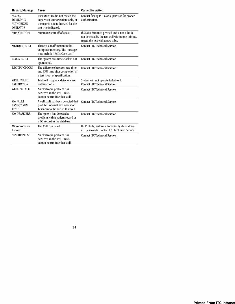
34
Hazard/Message Cause Corrective Action
ACCESS DENIED/UN- AUTHORIZED OPERATOR
User OID/PIN did not match the supervisor authorization table, or the user is not authorized for the test type indicated.
Contact facility POCC or supervisor for proper authorization.
Auto SHUT-OFF Automatic shut off of a test. If START button is pressed and a test tube is not detected by the test well within one minute, repeat the test with a new tube.
MEMORY FAULT There is a malfunction in the computer memory. The message may include “RxDx Case Lost”.
Contact ITC Technical Service.
CLOCK FAULT The system real-time clock is not operational.
Contact ITC Technical Service.
RTC/CPU CLOCKS The difference between real time and CPU time after completion of a test is out of specification.
Contact ITC Technical Service.
WELL FAILED CALIBRATION
Test well magnetic detectors are not functional.
System will not operate failed well. Contact ITC Technical Service.
WELL PCB VCC An electronic problem has occurred in the well. Tests cannot be run in either well.
Contact ITC Technical Service.
Wn FAULT CANNOT RUN TESTS
A well fault has been detected that prohibits normal well operation. Tests cannot be run in that well.
Contact ITC Technical Service.
Wn DBASE ERR The system has detected a problem with a patient record or a QC record in the database.
Contact ITC Technical Service.
Microprocessor Failure
The CPU has failed. If CPU fails, system automatically shuts down in 1.5 seconds. Contact ITC Technical Service.
SENSOR PULSE An electronic problem has occurred in the well. Tests cannot be run in either well.
Contact ITC Technical Service.
Printed From ITC Intranet

35
Printer and COM Warnings
Warning messages may also be displayed during operation of the printer or during transfer of data. The warning message indicates that the operation could not be completed and that corrective action must be taken. Instrument operation will continue if a Printer or COM warning is displayed.
The warning messages that may be displayed are described below.
Warning Message Cause Corrective Action
INT-PRINTER Either a paper jam has occurred in the internal printer, or the print head cannot move.
Add paper or free the print head. Reset INT PRINTER in the Set Output menu.
EXT-PRINTER An error condition has occurred in the external printer.
Consult the printer Operator’s Manual for assistance. Reset EXT PRINTER in the Set Output menu.
COM1 or COM2 A timeout occurred during transfer of data at the COM1 or COM2 port.
Check the cable connections as the port. If OK, the reason why data transfer has stopped at the port must be determined. Reset COM1 or COM2 to YES in the Set Output menu.
SYSTEM TESTS A series of system tests are available to check proper operation of various system components. These tests are listed below:
Test Description Keypad Test Tests the keypad for correct entered characters. LCD Test Tests the display for missing pixels. LED Test Tests the LEDs for illumination. COM1 Test Tests proper connection to first external source. COM2 Test Tests proper connection to second external source. EXTP Test Tests the external printer. INTP Test Tests the internal printer. Battery Check Tests battery charge. Display Wand Tests the barcode reader for proper operation. Beeper Tests the beeper for audible tone. E2 PROM Check Tests the system RAM memory. Fault Test View system faults. Print System Prints the system test results.
To Display System Information: 1. Display the second page of the main menu. 2. Press 7 to display system information.
Note: Version numbers of the system software are displayed. These may be needed for troubleshooting or ITC Technical Service assistance.
Printed From ITC Intranet

36
To Run a System Test: 1. Display the second page of the main menu. 2. Press 5 to display the first page of the System Test menu. Press MENU or 0 to display
the second page. 3. Select a test by pressing the corresponding numeral key. 4. Follow the instructions for each test as outlined in the following sections. To Test the Keypad:
1. Select the first System Test menu. 2. Press 1. The Keypad Test prompt is displayed. 3. Press each key and verify that the appropriate character is displayed:
Key Character Displayed
0 through 9 0 – 9 (same character as pressed) BACKSPACE H YES B NO G START1 K MENU1 I START2 L MENU2 J PRINT F
Note: A character is displayed when any key except PAPER FEED or CANCEL is pressed. 4. Press CANCEL to stop the test and return to the System Test menu.
To Test the LCDs: 1. Select the first System Test menu. 2. Press 2. The entire LCD display alternately turns light and dark. 3. Examine the LCD display while it is blinking to determine if any pixels are not being activated. 4. Press CANCEL to stop the test and return to the System Test menu.
To Test the LEDs: 1. Select the first System Test menu. 2. Press 3. The Detector and Heater LEDs flash at 1/2 second intervals. 3. Examine the LEDs to verify that each one illuminates. 4. Press CANCEL to stop the test and return to the System Test menu.
Note: Not all LEDs illuminate at the same brightness. The Power and Charge LEDs operate independently. The Power LED is ON whenever the unit is powered up, while the Charge LED is ON only when the unit is attached to the AC/DC Power Module.
To Test the COM1 or COM2 Ports: 1. Connect a personal computer to the COM port being tested. 2. Select the first System Test menu. 3. Press 4 or 5, depending on which COM port is being tested. 4. Verify that an acknowledgement message is displayed by the personal computer.
Note: This requires communication software on the PC to be running. To Test the External Printer:
1. Verify the system is connected to an external printer. 2. Select the first System Test menu. 3. Press 6. The External Printer prompt is displayed. 4. Press any key and verify that the corresponding character is printed on the external printer. 5. Press CANCEL to stop the test and return to the System Test menu.
Printed From ITC Intranet

37
To Test the Internal Printer: 1. Select the first System Test menu. 2. Press 7. The Internal Printer menu is displayed. 3. Select the desired option using the numeric key to start the test. 4. Examine the printouts to determine that the corresponding characters are legibly printed.
To Test the Battery: 1. Select the second System Test menu. 2. Press 1. The Battery Test prompt is displayed. 3. Verify that Battery OK is displayed. If the battery test is unacceptable, Battery BAD will be
displayed. CHARGING is displayed if the instrument is connected to the AC/DC Power Module. DISCHARGING is displayed if the instrument is being run from the battery.
4. Press CANCEL to stop the test and return to the System Test menu.
To Test a Connected Barcode Reader: 1. Select the second System Test menu. 2. Press 2. The Wand Reading prompt is displayed. 3. Scan a barcode label. Verify that the human-readable characters displayed match the label. 4. Press CANCEL to stop the test and return to the System Test menu.
To Run the Beeper Test: 1. Select the second System Test menu. 2. Press 3. The Beeper Test prompt is displayed. 3. Press any numeral key. Verify that the system beeps the corresponding number of times. 4. Press CANCEL to stop the test and return to the System Test menu.
To Test the E2 PROM: 1. Select the second System Test menu. 2. Press 4. The test is carried out automatically and the results displayed. 3. Press any key to return to the previous menu.
To View the System Fault List: 1. Select the second System Test menu. 2. Press 5. The System Faults listing is displayed. 3. Each listed component is followed by either OK if it is functioning properly or N/G if there is a
malfunction. Note: Refer to the Troubleshooting section for causes and corrective action for system faults.
To Print the System Test Results: 1. Select the second System Test menu. 2. Press 6. The Print System menu is displayed:
3. Press the numeral key corresponding to the option to be printed.
Printed From ITC Intranet
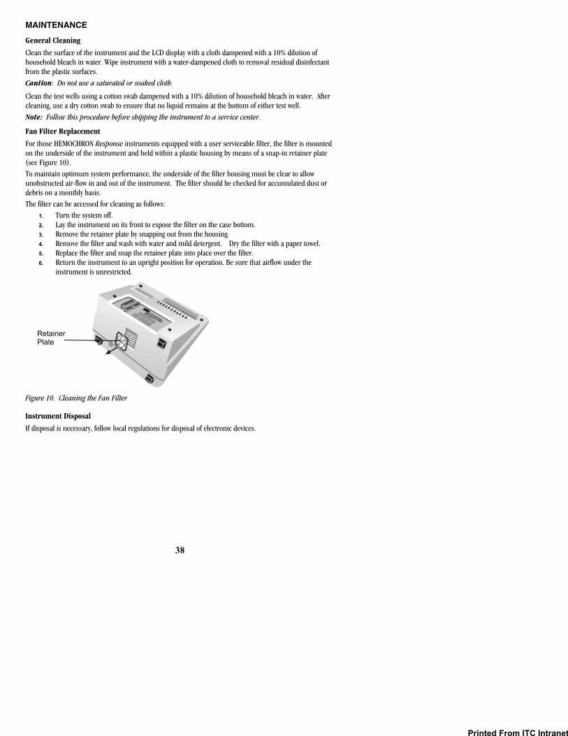
38
MAINTENANCE
General Cleaning
Clean the surface of the instrument and the LCD display with a cloth dampened with a 10% dilution of household bleach in water. Wipe instrument with a water-dampened cloth to removal residual disinfectant from the plastic surfaces. Caution: Do not use a saturated or soaked cloth.
Clean the test wells using a cotton swab dampened with a 10% dilution of household bleach in water. After cleaning, use a dry cotton swab to ensure that no liquid remains at the bottom of either test well. Note: Follow this procedure before shipping the instrument to a service center.
Fan Filter Replacement
For those HEMOCHRON Response instruments equipped with a user serviceable filter, the filter is mounted on the underside of the instrument and held within a plastic housing by means of a snap-in retainer plate (see Figure 10). To maintain optimum system performance, the underside of the filter housing must be clear to allow unobstructed air-flow in and out of the instrument. The filter should be checked for accumulated dust or debris on a monthly basis. The filter can be accessed for cleaning as follows:
1. Turn the system off. 2. Lay the instrument on its front to expose the filter on the case bottom. 3. Remove the retainer plate by snapping out from the housing. 4. Remove the filter and wash with water and mild detergent. Dry the filter with a paper towel. 5. Replace the filter and snap the retainer plate into place over the filter. 6. Return the instrument to an upright position for operation. Be sure that airflow under the
instrument is unrestricted.
Figure 10. Cleaning the Fan Filter
Instrument Disposal
If disposal is necessary, follow local regulations for disposal of electronic devices.
Retainer Plate
Printed From ITC Intranet
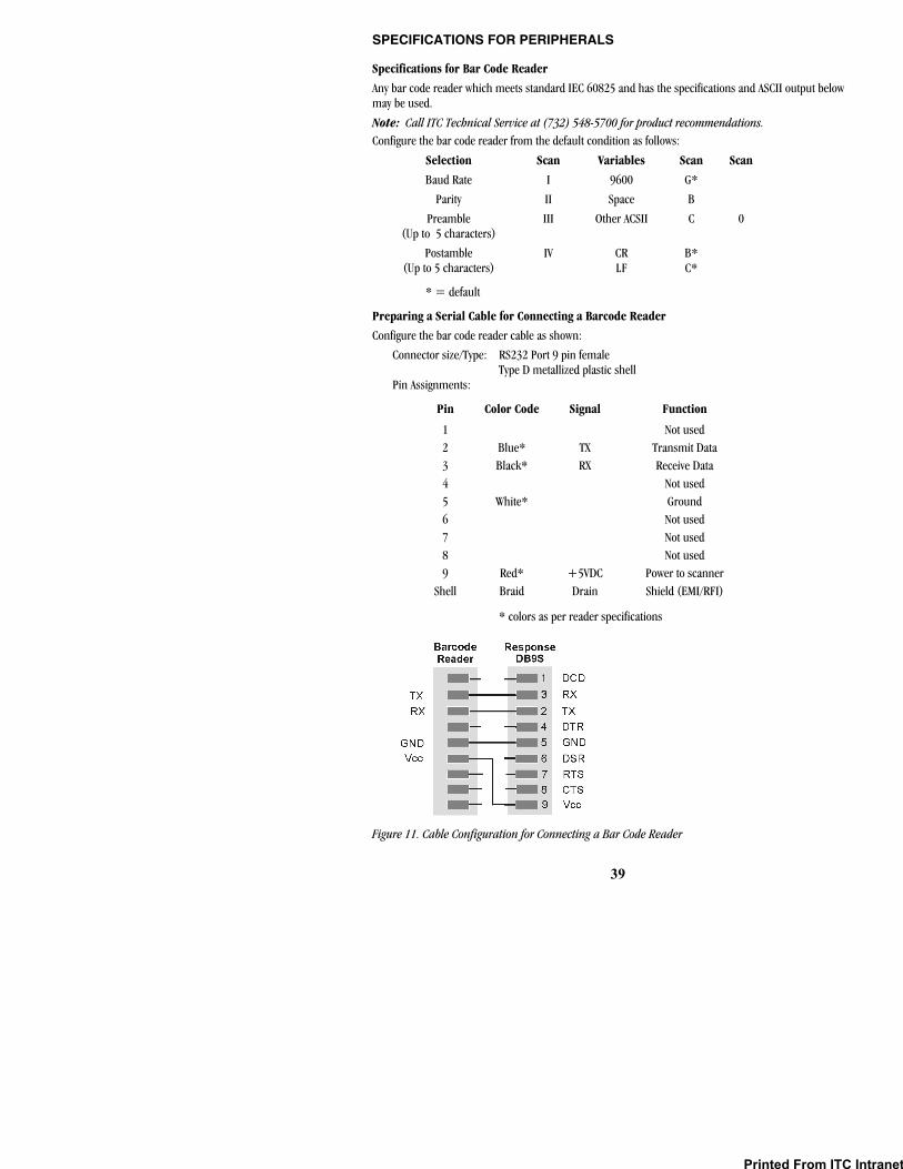
39
SPECIFICATIONS FOR PERIPHERALS
Specifications for Bar Code Reader
Any bar code reader which meets standard IEC 60825 and has the specifications and ASCII output below may be used.
Note: Call ITC Technical Service at (732) 548-5700 for product recommendations. Configure the bar code reader from the default condition as follows:
Selection Scan Variables Scan Scan
Baud Rate I 9600 G*
Parity II Space B
Preamble (Up to 5 characters)
III
Other ACSII
C
0
CR B* Postamble (Up to 5 characters)
IV LF C*
* = default
Preparing a Serial Cable for Connecting a Barcode Reader
Configure the bar code reader cable as shown:
Connector size/Type: RS232 Port 9 pin female Type D metallized plastic shell
Pin Assignments:
Pin Color Code Signal Function
1 Not used 2 Blue* TX Transmit Data 3 Black* RX Receive Data 4 Not used 5 White* Ground 6 Not used 7 Not used 8 Not used 9 Red* +5VDC Power to scanner
Shell Braid Drain Shield (EMI/RFI)
* colors as per reader specifications
Figure 11. Cable Configuration for Connecting a Bar Code Reader
Printed From ITC Intranet

40
Preparing a Serial Cable for Connecting a Printer or Computer
Cable configurations for connecting a serial printer or a computer depend upon the type of connector on the device (Figure 12). Use 6-wire or 8-wire RJ45 to RJ45 modular straight through connecting cable no longer than 25 feet plus an RJ45 to DB9 adapter.
Pin numbering on a RJ45 connector
Seiko Printer with DB9S
DCE/DTE Serial Printer with DB9S
Any DCE/DTE Serial Printer with DB9P
Any PC with DB9P
Any PC with a DB25P
Figure 12. Cable Configurations for Connecting a Printer or Computer
Printed From ITC Intranet

41
SAFETY STANDARDS
The HEMOCHRON Response instrument complies with the following safety standard requirements and directives:
CSA C22.2. 601.1. Medical Electrical Equipment – General Requirements for Safety
EN 60601-1 / IEC 60601-1/ UL 60601-1
Medical Electrical Equipment – General Requirements for Safety
EN 60601-1-2 / IEC 60601-1-2
Medical Electrical Equipment – Part 1-2 – General Requirements for Safety – Collateral Standard: Electromagnetic Compatibility – Requirements and Tests
EN 61000-3-2 Electromagnetic Compatibility – Limits – Limits for Harmonic Current Emissions
EN 61000-3-3 Electromagnetic Compatibility – Limits – Limitation of Voltage Changes, Voltage Fluctuations and Flicker in Public Low-voltage Supply Systems
EN 55011 Industrial, Scientific and Medical (ISM) Radio Frequency Equipment – Radio Disturbance Characteristics – Limits and Methods of Measurement
EN 61326 Electrical Equipment for Measurement, Control and Laboratory Use – EMC Requirements
Directives: 89/336/EEC and as amended by 91/263/EEC, 92/31/EEC, 93/68/EEC, 98/13/EC, and 98/79/EC
Printed From ITC Intranet

42
INDEX
9
911 attempts .............................................16, 29
A
attention label ...................................................4 automatic shutdown .........................................8
B
barcode reader ..................................................7 barcoded tube .................................................25 battery ...........................................................5, 7
charging .......................................................7 low battery warning......................................7
battery power remaining .................................19 battery test.......................................................37 baud rate .........................................................18 beep volume....................................................20
C
changing printed heading ...............................21 checking system operation..............................35 clock ................................................................13
displaying ...................................................13 format ........................................................12
coagulation testing description ...................................................2 tests run .......................................................2
COM port .........................................................19 commands ........................................................9 connecting
bar code reader ............................................7 personal computer.......................................7 printer ................................................6, 7, 19
Connecting Printer........................................................36
D
data logging .....................................................20 data management ...........................................30
database query ...........................................30 date format......................................................12 default assay....................................................13 definitions .........................................................3 deleting operator records ................................15 description
automatic shutdown ....................................8 display panel ................................................9 features ........................................................4 indicator LEDs ...........................................10 keypad..........................................................8
menus........................................................10 reagents......................................................11 test termination ...........................................8 tests ............................................................11
display brightness............................................20 display contrast ...............................................20 display of results .............................................25 downloading records.......................................18
E
erasing results .................................................18 ESV tube ..........................................................27 external printer use.........................................19
F
fan filter cleaning......................................................38
fault list ...........................................................37 flashlight time .................................................20
H
hazard and fault messages..............................33 HEMOCHRON Response
description ...................................................3 features ........................................................4 specifications ...............................................5
I
indicator LEDs.................................................10 instrument shutdown .....................................26 intended use......................................................2 internal printer use .........................................19
K
keypad ...............................................................8
L
language ..........................................................18 limitations .......................................................29
M
materials provided ............................................6 materials required ............................................6 menus .............................................................10
O
OID or PIN requiring entry of .......................................25
operating precautions .....................................29 operation
Printed From ITC Intranet
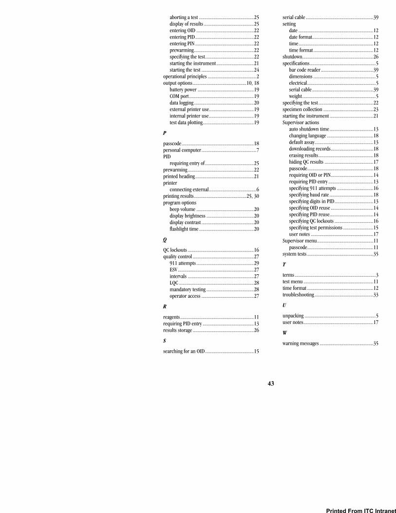
43
aborting a test ............................................25 display of results ........................................25 entering OID ..............................................22 entering PID...............................................22 entering PIN ...............................................22 prewarming................................................22 specifying the test.......................................22 starting the instrument ..............................21 starting the test ..........................................24
operational principles .......................................2 output options...........................................10, 18
battery power .............................................19 COM port....................................................19 data logging ................................................20 external printer use....................................19 internal printer use....................................19 test data plotting.........................................19
P
passcode..........................................................18 personal computer............................................7 PID
requiring entry of .......................................25 prewarming .....................................................22 printed heading ...............................................21 printer
connecting external......................................6 printing results..........................................25, 30 program options
beep volume ..............................................20 display brightness ......................................20 display contrast ..........................................20 flashlight time ............................................20
Q
QC lockouts .....................................................16 quality control .................................................27
911 attempts ..............................................29 ESV .............................................................27 intervals .....................................................27 LQC ............................................................28 mandatory testing ......................................28 operator access ..........................................27
R
reagents...........................................................11 requiring PID entry .........................................13 results storage .................................................26
S
searching for an OID.......................................15
serial cable ......................................................39 setting
date ............................................................12 date format.................................................12 time............................................................12 time format ................................................12
shutdown.........................................................26 specifications.....................................................5
bar code reader ..........................................39 dimensions ..................................................5 electrical.......................................................5 serial cable .................................................39 weight...........................................................5
specifying the test ............................................22 specimen collection ........................................23 starting the instrument ...................................21 Supervisor actions
auto shutdown time...................................13 changing language .....................................18 default assay...............................................13 downloading records..................................18 erasing results............................................18 hiding QC results .......................................17 passcode.....................................................18 requiring OID or PIN..................................14 requiring PID entry ....................................13 specifying 911 attempts .............................16 specifying baud rate ...................................18 specifying digits in PID...............................13 specifying OID reuse ..................................14 specifying PID reuse...................................14 specifying QC lockouts ...............................16 specifying test permissions ........................15 user notes ..................................................17
Supervisor menu.............................................11 passcode.....................................................11
system tests .....................................................35
T
terms.................................................................3 test menu ........................................................11 time format .....................................................12 troubleshooting ...............................................33
U
unpacking .........................................................5 user notes........................................................17
W
warning messages ...........................................35
Printed From ITC Intranet

HR1574 10/04
Printed From ITC Intranet