responsible environmental management of oil and natural gas
TRANSCRIPT

Responsible Environmental Management of Oil
and Natural Gas Activities in New Brunswick
Rules for Industry
February 15 2013
ii
Table of Contents Introduction vi The Need for Continuous Improvement vii Scope vii Definitions 92 10 Addressing Potential Concerns Associated With Geophysical (Seismic) Testing 1
11 Set-Backs for Seismic Energy Sources 1 12 Protecting Surface Water and Groundwater 1 13 Enhanced Measures to Address the Release of Water from Shot Holes 1 14 Responding to Gas Encountered in a Shot Hole 1 15 Plugging and Abandoning Shot Holes 2 16 Misfires 2
20 Preventing Potential Contaminants from Escaping the Well Bore 2
21 Use of Prescribed Drilling Fluids When Drilling Through Shallow (Non-Saline) Groundwater 2 22 Well Casing - General Provisions 2 23 Well Casing - Pressure Rating and Age 3 24 Well Casing ndash Joints 3 25 Well Casing - Surface Casing Vents 4 26 Well Casing - Use of Conductor Pipe and Casing 4 27 Well Casing - Surface Casing Depth 4 28 Well Casing - Minimum Barrier Protection 5 29 Well Casing - Use of Production Casing 5 210 Well Cementing - General Provisions 6 211 Well Cementing - Centralizers 7 212 Well Cementing - Extent of Conductor Casing Cement 7 213 Well Cementing - Extent of Surface Casing Cement 7 214 Well Cementing - Extent of Intermediate Casing Cement 7 215 Well Cementing - Extent of Production Casing Cement 8 216 Well Cementing - Locating the Cement Top and Remedial Cementing 8 217 Well Cementing - Setting (Wait) Period and Required Strength 9 218 Well Cementing - Testing and Evaluation 9 219 Well Cementing - Witnessing and Notification 10 220 Casing and Cementing Plans 11 221 Pressure Testing the Well Casing and Surface Equipment 11 222 Hydraulic Fracturing Treatment Plan and Notification 11 223 Pre-Fracturing Checklist and Certification 12 224 Pressure Monitoring Maximum Allowable Pressure and Termination of
Fracturing in Response to Unexpected Events 12 225 Ceasing Activities When Necessary to Protect Public Health Safety and
the Environment 13 226 Use of Certified Well Drilling Personnel 13 227 Remote Blow-Out Prevention Actuator 14 228 Enhanced Blow-Out Prevention Measures 14
iii
229 Investigation and Response - Surface Casing Vent Flow Gas Migration and Stray Gas 14
230 Well Plugging and Abandonment 14
30 Assessing Geological Containment Outside the Well Bore 15 31 Assessment of Inter-Wellbore Communication Prior to Hydraulic Fracturing 15 32 Assessment of Geological Containment Prior to Hydraulic Fracturing 15 33 Analysis of Response of Geological Formations to Hydraulic Fracturing 16 34 Restrictions and Special Requirements in Relation to Shallow Hydraulic Fracturing 16
40 Managing Wastes and Preventing Potential Contaminants from Escaping the Well Pad 16
41 Well Pad Construction 16 42 Use of Closed Loop Drill Fluid Systems 17 43 Emergency Containment of Hydraulic Fracturing Fluid 17 44 Waste Management Plan 17 45 Waste Management ndash General 18 46 Waste Management - Waste Characterization 18 47 Waste Management - On-site Disposal Restrictions 18 48 Waste Management - Flowback Water and Produced Water 18 49 Waste Management - Naturally Occurring Radioactive Materials (NORMs) 19 410 Waste Management- Use of Existing Wastewater Treatment Facilities 19 411 Spill Prevention Reporting and Response 20 412 Run-O Management 20 413 Chemical Management - General Provisions 20 414 Chemical Management ndash Transportation 21 415 Chemical Management - Chemical Inventory 21 416 Access Control 21 417 Storage Tanks Vessels and Containers 22 418 Enhanced Precautions for Sour Gas 22
50 Monitoring to Protect Water Quality 22
51 Water Well Testing 22 52 Surface Water Monitoring 23 53 Well Integrity Monitoring at Oil and Gas Wells 23
60 Providing for the Sustainable Use of Water 24
61 Water Management Plan 24 62 Water Management Plan - Water Conservation and Recycling 24 63 Water Management Plan - Hierarchy of Preferred Water Sources 24 64 Water Management Plan - Assessment of Proposed Water Sources 25 65 Water Management Plan - Water Use Monitoring and Reporting 26
70 Addressing Air Emissions Including Greenhouse Gases 26
71 Emission Limits 26 72 Emission Inventory 26 73 Emission Dispersion Modelling 27 74 Air Quality Monitoring at Source 27 75 Ambient Air Quality Monitoring 27
iv
76 Fugitive Emissions Management and Greenhouse Gas Reduction Plan 28 77 Greenhouse Gases - Reporting Emissions 28
80 Addressing Public Safety and Emergency Planning 29
81 Security and Emergency Planning For Oil and Gas Activities 29
90 Protecting Communities and the Environment 30 91 Vehicular Traffic - OversizeOvermass Loads and Weight Restrictions 30 92 Vehicular Traffic - Haul Route Planning 30 93 Vehicular Traffic - Road Use Agreements and Road System Integrity Studies 30 94 Noise Level Limits 31 95 Noise Mitigation and Monitoring 32 96 Visual impact- Screening Report and Mitigation Plan 32 97 Facility Siting Restrictions and Set-backs - General Provisions 33 98 Protecting Flood Prone Areas Wetlands and Watercourses 33 99 Protecting Public and Communal Water Supplies 34 910 Protecting Individual Water Supplies 35 911 Required Distances from Buildings and Other Cultural Features 35 912 Site Restoration 36 913 Site Remediation Standards for Contaminants 36 914 Addressing Induced Seismicity 36
100 Reducing Financial Risks and Protecting Landowner Rights 37
101 Financial Security for Damage 37 102 Water Supply Replacement or Restoration 38 103 Enhanced Financial Security for Well Abandonment 39 104 Mandatory Liability Insurance for Operators of Oil and Gas Activities 39 105 Land Agent Licensing and Standards of Conduct 39
110 Sharing Information 39
111 Prescribed Minimum Notification Radius for EIA Determination Reviews 39 112 Prescribed Minimum Notification Radius for Seismic Testing 40 113 Disclosure and Risk Assessment of Fracture Fluid Additives 40 114 Liaison Committees 40
APPENDIX 1 Minimum Set-backs for Seismic Energy Sources 42 APPENDIX 2 Surface Casing Vent Flow (SCVF)Gas Migration (GM) Testing Reporting and Repair 43 APPENDIX 3 Pre-Fracturing Checklist and Certification 46 APPENDIX 4 Investigation and Response to Public Safety and Environmental Hazards Resulting From Surface Casing Vent Flow Gas Migration and Stray Gas 48 APPENDIX 5 Waste Management 51 APPENDIX 6 Spill Prevention Reporting and Response 58 APPENDIX 7 Run-Off Management for Oil and Gas Well Pads 62 APPENDIX 8 Storage Tanks Vessels and Containers 64 APPENDIX 9 Water Well Testing in Proximity to Oil and Gas Activities 66
v
APPENDIX 10 Surface Water Monitoring 71 APPENDIX 11 Emission Reduction Measures for Petroleum Facilities 73 APPENDIX 12 Security and Emergency Planning For Oil and Gas Activities 75 APPENDIX 13 Highway Transportation Permits in New Brunswick 78 APPENDIX 14 Mitigation Measures for Road Traffic Due to Oil and Gas Activities 81 APPENDIX 15 Noise Impact Mitigation Measures for Construction and Operation of Oil and Gas Wells 82 APPENDIX 16 Visual Impact Mitigation Measures 83 APPENDIX 17 Site Restoration for Oil and Gas Activities 84 APPENDIX 18 Minimum Project Notification Radius for Proposed Oil and Gas Activities 87 APPENDIX 19 Fracture Fluid Disclosure and Risk Assessment 88
vi
Introduction These rules have been released in order to support New Brunswickrsquos on-going management of oil and gas activities and to ensure that the Province continues to have the tools needed to guide oil and gas exploration and extraction in an environmentally responsible manner They are based on recommendations contained in Responsible Environmental Management of Oil and Gas Activities in New Brunswick - Recommendations for Public Discussion which was released for public comment on May 17 2012 The rules incorporate input received during the subsequent 4 month public review period The requirements described in this document build upon existing regulations governing the oil and natural gas industry in New Brunswick and for the most part will be implemented as conditions to Approvals and Certificates of Determination issued under existing legislation including the Oil and Natural Gas Act Clean Environment Act the Clean Air Act and the Clean Water Act Some of the recommendations contained in Responsible Environmental Management of Oil and Gas Activities in New Brunswick - Recommendations for Public Discussion (May 2012) are action items for the Province They include
bull Enhancing certification and training requirements for oil and gas operators bull Monitoring the on-going development of fracturing fluids and technologies bull Identifying additional wastewater treatment and disposal options bull Enhancing the provincial water monitoring network bull Developing a water management strategy for oil and gas development bull Considering the possible introduction of water use permits bull Considering expanded ambient air quality monitoring by the Province bull Revenue Sharing bull Establishing an orphan oil and gas well fund bull Considering the development of guidelines for lease agreements bull Considering the establishment of an enhanced occurrence management system bull Considering the establishment of a new conflict resolution mechanism bull Considering the establishment of a contingency fund to address environmental issues that
may occur in future bull Publicizing the Provincersquos Environmental Requirements and Standards for Oil and Gas
Activities bull Public Disclosure of Environmental Assessment Information bull Enhanced On-line Access to Project-Specific Information bull Continuing to Enable Phased Reviews of Projects under the Environmental Impact
Assessment Regulation bull Assessing the Provincersquos enforcement capabilities bull Gathering additional scientific information bull Providing for continuous improvement of the Provincersquos regulatory program for oil and gas bull Enhancing cross-departmental coordination within the Provincial government bull Establishing training requirements for oil and gas operators about New Brunswickrsquos
environmental regulatory regime
vii
The above items will be addressed as part of future government initiatives including the forthcoming Oil and Gas Blueprint
The Need for Continuous Improvement
Developing rules for the responsible environmental management of oil and gas activities in New Brunswick is not a one-time activity Technology relating to unconventional oil and gas development is evolving rapidly In addition future experience with oil and gas activities in New Brunswick and elsewhere may suggest additional responses These rules will be used to manage oil and gas activity over approximately the next two years This will allow the Province industry and citizens of New Brunswick to obtain additional information about the size of the oil and gas resources in New Brunswick and the feasibility of its extraction Information collected during the various environmental monitoring activities required by the Province will also contribute valuable information of assistance in the future management of oil and gas activities in a New Brunswick context Scope The rules contained in this document are intended to apply to oil and gas activities and facilities located on either privately owned or provincially owned land They address all stages of land-based oil and natural gas production from exploration to abandonment however particular emphasis has been placed on the drilling and completion of oil and gas wells including hydraulic fracturing Unless otherwise indicated these requirements are not intended to apply retroactively to oil and gas facilities that have already been approved and constructed The information contained in this document is not an exhaustive list of the requirements to be met by proponents of oil and gas activities in New Brunswick Those who undertake oil and gas activities in New Brunswick are responsible for meeting all applicable requirements under the relevant legislation
1
10 ADDRESSING POTENTIAL CONCERNS ASSOCIATED WITH GEOPHYSICAL (SEISMIC) TESTING Implementing measures to reduce risks to public safety private property and the environment during seismic testing 11 SET-BACKS FOR SEISMIC ENERGY SOURCES The minimum set-back distances between seismic energy sources and structures including water wells are described in Appendix 1 12 PROTECTING SURFACE WATER AND GROUNDWATER All shot holes must be drilled using methods and materials that are acceptable to the regulator as described in Sections 13 14 and 15 below 13 ENHANCED MEASURES TO ADDRESS THE RELEASE OF WATER FROM SHOT HOLES If groundwater is released and comes to the surface as a result of the drilling of a shot hole or detonation of an explosive energy source the operator must ensure that a) all drilling that is in progress is discontinued and the regulator is notified b) no explosive charge is loaded into the shot hole c) the shot hole is plugged in a manner that is acceptable to the regulator so that that the flow is confined to the aquifer or stratum of origin d) step drilling procedures are implemented for subsequent adjacent shot hole drilling and e) a report on the flowing hole is immediately submitted to the regulator Acceptable methods include those described in the most recent version of Alberta Department of Sustainable Resource Development Exploration Directive 2006-17 Flowing Holes and Encountering Gas or other methods that have been pre-approved by the regulator Step drilling procedures mean that the depths of subsequent shot holes in the vicinity where the water was encountered must be adjusted as required to avoid further release of water A detailed description is provided in the above Directive 14 RESPONDING TO GAS ENCOUNTERED IN A SHOT HOLE If gas (eg methane) is encountered during the drilling of a shot hole the operator must ensure that a) the gas is immediately confined to its source or place of origin in a manner that prevents an adverse effect on human health public safety property or the environment and b) immediately after the gas has been confined in accordance with clause a) a report is submitted to the regulator Acceptable methods include those described in the most recent version of Alberta Department of Sustainable Resource Development Exploration Directive 2006-17 Flowing Holes and Encountering Gas or other methods that have been pre-approved by the regulator
2
15 PLUGGING AND ABANDONING SHOT HOLES The operator of a seismic testing program must ensure that shot holes are abandoned as follows a) a plug must be placed in the shot hole at a depth of at least 1 metre below the surface of the ground b) at least a 50 cm thickness of a bentonite sealing product (or an equivalent sealing product that has been approved by the regulator) must be placed on top of the plug followed by drill cuttings or other material obtained from the shot hole and thoroughly tamped c) all drill cuttings not required to fill the hole must be spread evenly over the ground surrounding the hole and d) all wires leading to the charge must be pulled tight and cut level with the surface of the ground after the charge has been detonated Bentonite is a form of clay that expands when exposed to water 16 MISFIRES An operator must develop and implement a code of practice describing the measures that will be taken in the event that an explosive charge fails to detonate The code of practice must be developed in consultation with Worksafe New Brunswick and the Department of Energy and Mines and must ensure that a) all necessary actions are taken so that a charge that failed to detonate does not present a hazard to persons or property and b) on completion of a project the permit holder will report the location of all unexploded charges to the Department of Energy and Mines
20 PREVENTING POTENTIAL CONTAMINANTS FROM ESCAPING THE WELL BORE Maintaining well integrity and reducing the potential for unintentional releases of substances such as fracturing fluids drilling fluids flowback water produced water and natural gas from the horizontal or vertical segments of oil and gas wells 21 USE OF PRESCRIBED DRILLING FLUIDS WHEN DRILLING THROUGH SHALLOW (NON-SALINE) GROUNDWATER The well operator must use air freshwater freshwater-based or another drilling fluid acceptable to the regulator during the drilling of a well until the surface hole has been drilled and all porous strata that contain non-saline groundwater have been isolated from the drilling fluid by the installation and cementing of surface casing 22 WELL CASING - GENERAL PROVISIONS The operator must install steel or steel alloy casing that can withstand the forces of tension collapse and burst to which that casing will be subject during its installation cementing subsequent drilling hydraulic fracturing and oil and gas production The casing must also be designed to withstand other anticipated conditions including corrosion from hydraulic fracturing proppants and subsurface geochemistry At a minimum the casing must meet the design criteria specified in the most recent version of Directive 010 - Minimum Casing Design Requirements prepared by the Alberta Energy Resources Conservation Board (ERCB)
3
At a minimum the operator should install casing that is manufactured to the specifications defined in the most recent versions of American Petroleum Institute (API) Specification 5CT Specification for Casing and Tubing and International Organization for Standardization (ISO) Standard 11960 Steel Pipes for use as Casing or Tubing for Wells The casing should also meet or exceed the performance standards in the most recent version of API Technical Report TR5C3 Technical Report on Equations and Calculations for Casing Tubing and Line Pipe Used as Casing 23 WELL CASING - PRESSURE RATING AND AGE With the exception of the conductor pipe all casing installed in the well bore that will be subjected to hydraulic fracturing as part of well completion must have an internal pressure rating that is at least 10 greater than the anticipated maximum pressure to which the casing will be exposed during hydraulic fracturing and the lifetime of the well If used or reconditioned casing is installed it must be tested to ensure that it meets American Petroleum Institute (API) performance requirements for new casing If an operator proposes to hydraulically fracture a well five or more years after the casing and cementing was initially installed then as part of the application for a permit to carry out this activity the operator must provide evidence to the regulator (such as casing wear logs cement evaluation logs an assessment of casing corrosion or mechanical integrity tests) that the well cementing and casing is of sufficient strength and condition to maintain well integrity during the proposed hydraulic fracturing 24 WELL CASING - JOINTS All joints in casings used in a well bore including conductor casing but excluding a conductor pipe must be threaded rather than welded Welding at casing bowls must be done in accordance with acceptable welding procedures developed from the most recent versions of a) American Petroleum Institute (API) Specification 6A Specification for Wellhead and Christmas Tree Equipment b) Canadian Standards Association (CSA) Standard Z184 Standards for Gas Pipeline Systems c) National Association of Corrosion Engineers (NACE) Standard MR-01-75 Materials for use in H2S-containing Environments in Oil and Gas Production and d) Section IX of American Society of Mechanical Engineers (ASME) Boiler and Pressure Vessel Code Threaded casing and tubing joint connection make-up and torque procedures must meet the specifications defined in the most recent version of American Petroleum Institute (API) Recommended Practice 5C1 Recommended Practice for Care and Use of Casing and Tubing For wells that will be completed using hydraulic fracturing casing torque data must be recorded in the daily tour sheets for any casing or tubing strings that are primary or secondary barriers for hydraulic fracturing operations This casing torque data must be retained by the operator and made available to the regulator upon request All joint connection compounds used by the operator must meet the performance requirement specifications as defined in the most recent versions of American Petroleum Institute (API) Recommended Practice 5A3 Recommended Practice on Thread Compounds for Casing Tubing Line Pipe and Drill Stem Elements and International Organization for Standardization (ISO) Standard 13678 Evaluation and Testing of Thread Compounds for Use with Casing Tubing and Line Pipe
4
25 WELL CASING - SURFACE CASING VENTS All wells completed to produce oil or natural gas (including wells that are shut in for future production) must be equipped with surface casing vents that leave the annulus between the second casing string and the surface casing open to the atmosphere (except during a pressure test or while conducting maintenance or other work on the well) The intent is to ensure that any build-up of gas pressure in the annulus between the second casing string and the surface casing as a result of a leak can be easily detected and will not result in the flow of gas into the surrounding aquifer or geological formation In situations where it is desirable to control surface casing vent flow the operator may choose to install a burst plate or pressure release valve on the casing vent Casing vents must have a minimum diameter of 50 mm extend at least 60 cm above ground and terminate in the atmosphere in a manner so that any flow is directed either in a downward direction or parallel to the ground The working pressure rating in kilopascals of all parts of the surface casing vent must be at least 25 times the numerical equivalent of the surface casing depth in metres The well operator must monitor report assess and address surface casing vent flows (SCVFs) in accordance with the requirements described in Appendix 2 See also ldquoWell Integrity Monitoring at Oil and Gas Wellsrdquo under Section 50 and ldquoInvestigation and Response - Surface Casing Vent Flow Gas Migration and Stray Gasrdquo elsewhere in this Section 26 WELL CASING - USE OF CONDUCTOR PIPE AND CASING The operator must install such conductor pipe as is necessary to maintain a stable well bore prevent groundwater infiltration and keep the unconsolidated surface material in place during drilling operations Use of conductor casing to facilitate well control is required when a) an operator drills in a location where formation pressures are not known (eg when drilling an explorationdelineation well) b) there is potential to encounter a hydrocarbon-bearing zone during drilling of the surface hole or c) the required surface casing depth is greater than 450 metres If conductor casing is used to facilitate well control the conductor casing must be set at a depth of not less than 20m and a Class I diverter system must be installed in accordance with the most recent version of Alberta Energy Resources Conservation Board (ERCB) Directive 036 Drilling Blowout Prevention Requirements and Procedures 27 WELL CASING - SURFACE CASING DEPTH Surface casing is required for all oil or natural gas wells drilled in New Brunswick and the operator must ensure that the depth of the surface casing extends to the greater of a) a depth of at least 25 metres below all porous strata that contain non-saline groundwater as determined by a qualified professional engineer or geoscientist or b) a calculated casing depth based on the most recent version of Alberta Energy Resources Conservation Board (ERCB) Directive 008 Surface Casing Depth Minimum Requirements The operator must not use the surface casing string as the production casing string
5
Notwithstanding any other provision of this section the regulator may require the operator to install surface casing to a greater or lesser depth as the regulator considers appropriate to address site specific geology Further to the above the operator must ensure that a) the surface casing is set into a competent zone that can withstand the anticipated pore pressure of completing the next drilling section and b) the surface casing is run and cemented as soon as possible after the surface hole has been circulated and conditioned Surface casing should not extend into zones known to contain shallow gas In the event that such a zone is encountered before the non-saline groundwater is cased off the operator must take all necessary action required to get the well under control to prevent formation gas from entering zones of non-saline groundwater The operator must notify the regulator within 12 hours of such an event If a well control incident (kick) occurs while drilling the surface hole the operator must immediately report the following information to the regulator a) the well location b) the time and date of occurrence c) the depth and duration of occurrence d) the kick volume and e) the final drilling fluid weight that was required to control occurrence 28 WELL CASING - MINIMUM BARRIER PROTECTION Casing for all wells subject to hydraulic fracturing must be designed to provide acceptable barrier protection during hydraulic facture stimulation operations The main purpose of barrier protection is to prevent the loss of well control Surface casing and casing cement are not considered pressure barriers and must never be exposed to any hydraulic fracture stimulation pressures Casing for wells a) in a new geological basin geologic formation or geographic region as identified by the regulator or b) in a known geologic basin geologic formation or geographic region where there is a major change or shift in hydraulic fracture stimulation design must be designed to provide both primary and secondary barrier protection during hydraulic fracture stimulation operations through the use of a combination of intermediate casing production casing production liner tubing andor tie-back string The secondary barrier must be designed and installed in a manner that will a) provide protection in the event of a mechanical failure of the primary barrier (ie the casingtubing used to transport the fracturing fluids into the formation under pressure) during hydraulic fracture stimulation operations and b) provide well control and an ability to repair or replace the primary barrier in the event of a failure of the primary barrier 29 WELL CASING - USE OF PRODUCTION CASING In wellbores subjected to hydraulic fracturing operations where intermediate casing is not being installed production casing must be installed and run to surface In wellbores where intermediate casing is installed the regulator may allow the use of a production liner instead of a production casing to surface A request for use of a production liner must be made in writing and include supporting documentation showing that the intermediate casing is adequately engineered to ensure that public health and safety and environmental protection would not be compromised
6
Where the use of a production liner is approved by the regulator the operator must install a tie-back string or tubing with downhole mechanical isolation (ie packer or polished bore receptacle) in the wellbore for use in all hydraulic fracture stimulation operations 210 WELL CEMENTING - GENERAL PROVISIONS The casing in an oil or gas well must be sufficiently cemented to a) secure the casing in the well bore b) effectively control the well and prevent the upward migration of fluids at all times and under all reservoir conditions (ie proper cementation of the well casing across vertically impermeable zones and groundwater zones) c) ensure that all zones containing non-saline groundwater are isolated and sealed off to effectively prevent contamination or depletion of such water and d) ensure that all potentially productive zones (zones capable causing annular over-pressurization) or corrosive zones are isolated and sealed off to the extent that such isolation is necessary to prevent vertical migration of fluids or gases behind the casing (eg gas flow in the annulus) At a minimum a) all cement must conform to the most recent version of American Petroleum Institute (API) Specification 10A Specifications for Cement and Material for Well Cementing or equivalent and b) the cement slurry must be prepared in a manner so as to minimize its free water content in accordance with the above API specification The density of the cement slurry must be based upon a laboratory free-fluid separation test demonstrating an average fluid loss of no more than 6 millilitres per 250 millilitres of cement tested in accordance with the most recent version of American Petroleum Institute (API) Recommended Practice 10 B-2 Recommended Practice for Testing Well Cements In areas of known shallow gas that could cause poor cement bonding or reduce cement integrity the operator must investigate the use of gas migration mitigation methods such as cement systems that reduce cement slurry porosity and permeability improve fluid loss control andor build gel strength rapidly The regulator may require that a prescribed cement mixture be used in any well or any area where local conditions suggest that a specific cement mixture is necessary The regulator may also require any necessary change to the cementing procedure Prior to cementing the surface intermediate and production casings the well bore must be conditioned to help ensure an adequate cement bond between the casing and the formation The cement should be mixed and pumped at a rate and in a flow regime that ensures consistent slurry density and inhibits channelling of the cement in the annulus For all casing cementing operations a well site representative provided by the well operator must remain on site throughout the cementing process and monitor the cementing during the mixing and pumping During placement of the cement the well site representative must monitor pump rates to verify they are within design parameters so as to ensure proper displacement efficiency Well cementing reports must be retained by the operator for the life of the well and submitted to the regulator on request The cement reports must include a) the volumes of cement pumped b) the types of cement used c) a description of cement additives that were employed d) the dates and times of
7
cementing e) cement slurry weights f) the volume of cement returns at surface (if any) g) the estimated or measured cement level in annulus (if no returns) and h) details of any problems encountered andor remedial work that was performed See the ldquoWell Cementing - Locating the Cement Top and Remedial Cementingrdquo subheading elsewhere in this Section 211 WELL CEMENTING - CENTRALIZERS All casing must be adequately centralized to position the casing strings within the well bore to assure that a cement sheath surrounds the outside of the casing The following installation requirements apply a) surface casing must be centralized at the top and bottom of the casing and at intervals of 50 metres or closer along the entire casing length and b) intermediate and production casing must be centralized at the top and bottom of all productive formations and at intervals of 50 metres or closer through areas that will be cemented and through to the required top of cement Additional centralizers must be placed where necessary to ensure that casing strings are centralized in a manner that will provide for proper zonal isolation by the cement Centralizers and their placement must also meet the standards set out in the most recent version of American Petroleum Institute (API) Recommended Practice 10D-2 Recommended Practice for Centralizer Placement and Stop Collar Testing and the most recent version of API Technical Report 10TR4 Technical Report on Considerations Regarding Selection of Centralizers for Primary Cementing Operations 212 WELL CEMENTING - EXTENT OF CONDUCTOR CASING CEMENT It is required that conductor casing be cemented to its full length and that the drilled diameter of the bore hole be at least 100 millimetres larger than the diameter of the conductor casing If the cement job fails to retain its integrity drilling must be suspended and remedial action taken If a diverter is installed on the conductor casing it must be cemented along its full length using the circulation method 213 WELL CEMENTING - EXTENT OF SURFACE CASING CEMENT It is required that surface casing be run and cemented as soon as practicable after the hole has been circulated and conditioned and that surface casing be cemented along its full length using the circulation method The use of fillers or additives that reduce the compressive strength of surface casing cement below the minimum required strength must be avoided The required cement volume must be based on calculated hole-size measurements plus a minimum of 50 excess cement or hole-size measurements taken from a calliper log plus a minimum of 20 excess cement volume Flow returns must be visually monitored 214 WELL CEMENTING - EXTENT OF INTERMEDIATE CASING CEMENT If intermediate casing is installed in an oil or gas well the intermediate casing must be cemented from the shoe to a point at least 200 metres above the shoe or if any porous zone is open to the wellbore above the casing shoe the casing must be cemented from the shoe up to a point at least 200 metres above the top of the shallowest porous zone or to a point at least 50 meters above the shoe of the next
8
shallower casing string The cementing must be accomplished using the circulation method unless the use of an alternative method is approved by the regulator The required cement volume must be based on hole-size measurements taken from a calliper log plus a minimum of 20 excess cement volume and the top of cement must be located by a cement top locating log and reported to the regulator The use of cement additives or alternatives that enhance the integrity of the cement bond cement strength or zone containment is permitted 215 WELL CEMENTING - EXTENT OF PRODUCTION CASING CEMENT It is required that the production casing be cemented from the shoe to a point at least 200 metres above the shoe or if any porous zone is open to the wellbore above the casing shoe the casing must be cemented from the shoe up to a point at least 200 metres above the top of the shallowest porous zone or to a point at least 50 meters above the shoe of the next shallower casing string Cementing must be accomplished using the circulation method unless the use of an alternative method is approved by the regulator The required cement volume be based on hole-size measurements taken from a calliper log plus a minimum of 20 excess cement volume The top of cement be located by a cement top locating log and reported to the regulator When production liners are permitted by the regulator they must be cemented over their entire length Alternative completion techniques may be acceptable to the regulator if it can be demonstrated that they provide equivalent hydraulic isolation The required cement volume must be based on hole-size measurements taken from a calliper log plus a minimum of 20 excess cement volume 216 WELL CEMENTING - LOCATING THE CEMENT TOP AND REMEDIAL CEMENTING Surface Casing If cement returns are not obtained at the surface or if the cement level in the annulus drops below the surface the results of a cement top log and a proposed remedial cementing plan must be submitted to the regulator for approval Remedial cementing in accordance with the approved plan must be achieved prior to drilling the next hole section Intermediate Casing If the required cement top is not achieved the results of the cement top log and a proposed remedial cementing plan must be submitted to the regulator for approval prior to its implementation Remedial cementing in accordance with the approved plan must be achieved prior to drilling the next hole section Production Casing If the required cement top is not achieved the results of cement top log and a proposed remedial cementing plan must be submitted to the regulator for approval The approved plan must be implemented a) prior to commencement of hydraulic fracturing operations or b) within 60 days of rig release or c) prior to the commencement of well completion activities
9
An operator may submit proposed remedial cementing plans to the regulator in advance and the regulator may approve the plans in advance so that the approved plans can be immediately implemented by the operator as required 217 WELL CEMENTING - SETTING (WAIT) PERIOD AND REQUIRED STRENGTH After cement is placed behind any casing installed below the conductor pipe the operator must not disturb the casing until the cement achieves a minimum compressive strength of 3500 kPa The casing must not be disturbed for a minimum of 8 hours The operator may request approval from the regulator to reduce the prescribed 8 hour wait time prior to casing disturbance if a) the operator has bench tested the actual cement batch and blend using mix water from the actual source for the job and determined that 8 hours is not required to reach a compressive strength of 3500 kilopascals or b) special cement or additives that reduce setting time are used Such approval may be granted at the discretion of the regulator A pressure test on casings or liners that will be exposed to hydraulic fracture stimulation pressures must not commence until at least 7 days after the primary cementing operations are completed on those casings or liners
See the ldquoPressure Testing the Well Casing and Surface Equipmentrdquo subheading elsewhere in this section 218 WELL CEMENTING - TESTING AND EVALUATION Testing of Cement Characteristics It is required that tests be made on representative samples of the cement mixtures plus and additives using the water source that will be used to prepare the slurry These tests must be conducted using the equipment and procedures adopted by the American Petroleum Institute (API) as published in the most recent version of API Recommended Practice 10B Recommended Practice for Testing Well Cements Test data showing competency of the proposed cement mixture must be kept on file by the operator and furnished to the regulator on request Formation Leak-Off Tests (LOT) Formation Integrity Tests (FIT) Unless determined otherwise by the regulator the operator must conduct a formation leak-off or formation integrity test after drilling out below the surface casing shoe and below the intermediate casing shoe in order to a) verify the integrity of the cement in the casing annulus at the casing shoe and b) determine that formation integrity at the casing shoe is adequate to meet the maximum anticipated well bore pressure throughout the next drilling section andor at total depth Cement Evaluation - General The regulator may require that the operator evaluate the quality of the cement job including the cement-to-casing and cement-to-formation bonds Acceptable cement evaluation logs include radial bond logs or omni-directional bond logs in combination with a cement bond log (CBL)
10
When a cement evaluation log is required as described below it must be interpreted and signed by a qualified professional The interpretation must include an opinion as to the ability of the installed cement to serve its intended purpose including the prevention of migration of fluids within the annulus Cement Evaluation - Surface Casing The operator must run a cement evaluation log or other cement evaluation technique approved by the regulator to determine the quality of cement outside the surface casing if a) there is any reason to doubt the effectiveness of surface casing cementation as evidenced by abnormal monitoring indications during the cementing operation or upon post cement analysis or b) a shallow gas zone is encountered prior to the setting of surface casing and the surface casing is set across the gas producing zone If the cement bond is not adequate to isolate the well bore from non-saline groundwater and prevent the upward migration of fluid within the annulus remedial cementing will be required and a remedial plan must be submitted to the regulator for approval Cement Evaluation - Intermediate Casing The operator must run a cement evaluation log from the top of the shallowest porous zone to the top of cement in order to determine if hydraulic isolation has been achieved If the cement bond is not adequate to isolate these zones remedial cementing will be required and a remedial plan must be submitted to the regulator for approval and must be implemented prior to drilling ahead Cement Evaluation - Production Casing Prior to perforating the casing or initiating a hydraulic fracturing program the operator must run a cement evaluation log from the top of the shallowest porous zone to the top of cement in order to determine if hydraulic isolation has been achieved If the cement bond is not adequate to isolate these zones remedial cementing will be required A remedial plan must be submitted to the regulator for approval and must be implemented prior to commencing hydraulic fracturing An operator may submit proposed remedial cementing plans to the regulator in advance and the regulator may approve the plans in advance so that the approved plans can be immediately implemented by the operator as required 219 WELL CEMENTING - WITNESSING AND NOTIFICATION The operator must notify the regulator at least 24 hours prior to commencement of surface casing cementing The regulator may also require notification prior to the running and cementing of other casing strings on a case-by-case basis A qualified professional (ie wellsite supervisor a representative of a well service company or other third party company) must be retained by the well operator to witness the operations and certify in writing that they were conducted in accordance with the approved program
11
220 CASING AND CEMENTING PLANS It is required that casing and cementing plans be submitted to the regulator in support of an application to approve a proposed well These plans must be available at the well site for the duration of casing and cementing operations Any revisions to the casing and cementing plans made as a result of on-site decisions and must be documented by the operator and immediately submitted to the regulator 221 PRESSURE TESTING THE WELL CASING AND SURFACE EQUIPMENT Prior to drilling out the surface intermediate and production casing the operator must ensure that the following components are pressure tested blow-out preventer casing string stabbing valve inside blow-out preventer lower kelly valve choke manifold bleed-off and kill line and all associated valves in compliance with the most recent version of Alberta Energy Resources Conservation Board (ERCB) Directive 036 Drilling Blowout Prevention Requirements and Procedures Prior to the start of a hydraulic fracturing program all cemented casing strings and all tubing strings to be utilized in the hydraulic fracturing operations must be tested with fresh water mud or brine to a pressure not less than 3500 kilopascals greater than the anticipated maximum pressure to be experienced during either the hydraulic fracturing or the life of the completion If at the end of 30 minutes of such testing the pressure shows a drop of 10 or more from the original test pressure the regulator must be notified and hydraulic fracturing must not commence until the relevant condition is corrected The condition of a casing removed from service in accordance with the preceding sentence will be deemed to be corrected only after the casing demonstrates less than a 10 drop in pressure after being subjected to a subsequent 30 minute pressure test of the type described above Prior to commencing a hydraulic fracturing stage and the pumping of hydraulic fracturing fluid the injection lines manifold associated valves fracture head or tree and any other wellhead component or connection not previously tested must be tested with fresh water mud or brine to a pressure not less than 3500 kilopascals greater than the anticipated maximum pressure to be experienced during the hydraulic fracturing with less than a 10 pressure loss If at the end of 30 minutes of such testing the pressure shows a drop of 10 or more from the original test pressure the regulator must be notified and hydraulic fracturing must not commence until the relevant condition is corrected The condition of a component removed from service in accordance with the preceding sentence will be deemed to be corrected only after the retested component assembly demonstrates less than a 10 drop in pressure after being subjected to a 30 minute pressure test of the type described above Records of all pressure tests must be retained by the operator and submitted to the regulator on request 222 HYDRAULIC FRACTURING TREATMENT PLAN AND NOTIFICATION At least 3 days prior to initiating a hydraulic fracturing program the operator must submit a fracturing treatment plan to the regulator for information purposes The plan must include a) the date on which the hydraulic fracturing is expected to commence b) a profile of the anticipated pressures and fluid volumes for pumping each stage c) a description of the planned treatment interval (ie location of top and bottom of perforations expressed in both True Vertical Depth and True Measured Depth d) the total number of stages and total estimated volume of water and fracture fluid that will be used for all stages of the hydraulic fracturing operation and e) the casing and surface equipment test pressures
12
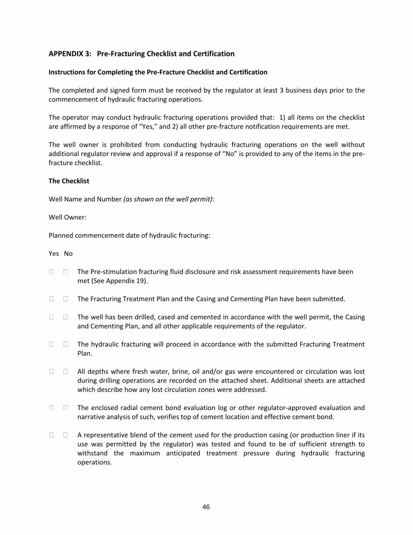
The Plan must also verify that the operator has made contact with any adjacent operators that are drilling completing or operating an oil or gas well within twice the planned fracture half-length distance and that arrangements have been made to cooperate through notifications and monitoring of all drilling and completion operations to reduce the possibility of unintended entry of water gas oil or other formation fluid into a well bore The submission must be updated after the hydraulic fracturing program has been completed (to compare the planned characteristics of the hydraulic fracturing program with the actual characteristics) and must be included in the well completion report and submitted to the regulator within 30 days of the conclusion of hydraulic fracturing program See also ldquoWater Management Plan - Water Use Monitoring and Reportingrdquo under Section 60 and ldquoDisclosure and Risk Assessment of Fracture Fluid Additivesrdquo under Section 110 ldquoFracture Half-lengthrdquo means the radial distance initiated from the subject well bore to the outer tip of a fracture propagated by fracturing 223 PRE-FRACTURING CHECK LIST AND CERTIFICATION An operator of an oil or gas well that will be stimulated using hydraulic fracturing must complete sign and submit a Pre-Fracturing Checklist and Certification at least 3 days prior to commencement of a hydraulic fracturing program The checklist must be signed and dated by an authorized representative of the operator Among other things the checklist requires the operator to attest that the operator has met or will meet all relevant casing cementing and pressure testing requirements and requires the operator to acknowledge its obligations to monitor pressures and notify the regulator and cease the hydraulic fracturing operation as described in Section 224 below A Pre-Fracturing Checklist and Certification form is included in Appendix 3 224 PRESSURE MONITORING MAXIMUM ALLOWABLE PRESSURE AND TERMINATION OF FRACTURING IN RESPONSE TO UNEXPECTED EVENTS The operator must continuously monitor and record the following parameters during each stage of a hydraulic fracturing program a) surface injection pressure b) slurry rate c) proppant concentration d) fluid rate and e) all annuli pressures (for stimulation operations where there is an intermediate casing this includes the pressure between the intermediate casing and production casing) The hydraulic fracturing treatment pressure must not exceed the test pressure of any given component at any time during hydraulic fracturing operations Differential pressures across the walls of any casing string must not exceed 80 of the casingrsquos American Petroleum Institute (API) rated minimum internal yield pressure throughout the hydraulic fracturing treatment The operators records of the pressure monitoring must be submitted to the regulator within 30 days after stimulation operations are complete unless a more immediate notification is required as described below Hydraulic fracturing must be immediately terminated and the operator must report the occurrence to the regulator within 24 hours if a) the pressure limit described above is exceeded or b) a volume of
13
fluid circulates to the surface that is in excess of a volume that could reasonably be expected due to temperature and pressure expansion or c) the annulus pressure increases by more than 3500 kilopascals during stimulation or d) any anomalous pressure andor flow condition is indicated or occurring including a significant deviation from the treatment plan or e) an operator has any reason to suspect a failure of a casing or casing cement or the lack of isolation of any sources of non-saline groundwater If hydraulic fracturing is terminated for any of the reasons described in this Section the operator must a) report to the regulator all details relating to the incident within 15 days of the occurrence and b) perform diagnostic testing and if the testing reveals that a failure has occurred the operator must shut-in the well and isolate the perforated portion of the well casing as soon as is reasonably practical Hydraulic fracturing must not recommence unless the situation has been resolved to the satisfaction of the regulator 225 CEASING ACTIVITIES WHEN NECESSARY TO PROTECT PUBLIC HEALTH SAFETY AND THE ENVIRONMENT If an operator is not able to effectively repair a deficiency in the design construction completion or operation of an oil or gas well so as to protect public health safety and the environment (including but not limited to all sources of non-saline groundwater and all surface waters potentially affected by the well) the operator must cease operations and plug and abandon the well in such a manner that it does not represent a hazard to public health safety and the environment 226 USE OF CERTIFIED WELL CONTROL PERSONNEL It is required that the drilling contractor retained by the operator possess a valid first line supervisorrsquos blow-out prevention certificate or well service blow-out prevention certificate issued by a recognized petroleum industry training service (eg ENFORM) that addresses blow-out prevention and kick control procedures The operator must arrange for or provide a) a well site representative (other than the rig manager) who is responsible for the supervision of the drillingservicing operations and b) an on-site rig manager who is responsible for the supervision of the drillingservicing rig The well site representative and the rig manager must each possess a valid second line supervisorrsquos certificate in well control procedures issued by a recognized petroleum industry training service (eg ENFORM) The well site representative and the rig manager must not supervise drilling or well servicing operations at more than one location simultaneously The well site representative and the rig manager may travel off-site however they must be at all times be capable of returning to the site within a maximum of two hours When potential hydrocarbon-bearing zones have been penetrated either the well-site representative or the rig manager must be on site while tripping in or out of the well If it becomes necessary to make an unscheduled tripping when neither of these individuals is present the tripping may commence immediately after contacting the well-site representative or rig manager The notified individual(s) must
14
return to the well site immediately During well control situations both of these individuals must be on site If either of the above personnel are found to not possess a valid certificate as described above the regulator may require the operator to suspend drilling operations as soon as it is safe to do so and to require that operations not resume until such persons are replaced with personnel having the required certification are provided ENFORM is a safety association serving Canadarsquos oil and gas industry 227 REMOTE BLOW OUT PREVENTION ACTUATOR Blow out prevention equipment installed at wells that will be subject to hydraulic fracturing must include a remote blow-out prevention (BOP) actuator that is a) powered by a source other than rig hydraulics and b) located at least 25 metres from the wellhead All lines valves and fittings between the BOP and the remote actuator and any other actuator must be flame resistant and have a working pressure rating higher than the maximum anticipated wellhead surface pressure 228 ENHANCED BLOW-OUT PREVENTION MEASURES The Province will enhance its existing blow-out prevention and control measures by adopting and imposing procedures for drilling and well servicing such as those set out in the latest versions of Alberta Energy Resources Conservation Board (ERCB) Directive 036 Drilling Blowout Prevention Requirements and Procedures and Directive 037 Service Rig Inspection Manual When drilling in areas where shallow methane may be present adequate safety measures must be taken including the use of proper well control measures and flare lines or stacks 229 INVESTIGATION AND RESPONSE - SURFACE CASING VENT FLOW GAS MIGRATION AND STRAY GAS The Province has developed a set of requirements addressing the investigation of and response to surface casing vent flow gas migration and stray gas Additional detail is provided in Appendix 4 230 WELL PLUGGING AND ABANDONMENT The Province will enhance its well plugging and abandonment requirements by adopting and imposing the procedures set out in the latest version of Alberta Energy Resources Conservation Board (ERCB) Directive 020 Well Abandonment
15
30 ASSESSING GEOLOGICAL CONTAINMENT OUTSIDE THE WELL BORE Reducing the potential for substances such as fracturing uids drilling uids and hydrocarbons to reach water wells or the surface via underground fractures faults abandoned oil or gas wells or a conning layer that is otherwise inadequate 31 ASSESSMENT OF INTER-WELLBORE COMMUNICATION PRIOR TO HYDRAULIC FRACTURING Prior to initiating a hydraulic fracturing program in any oil or gas well the operator must prepare a fracture assessment (model) of the potential for inter-wellbore communication between the stimulated well and any adjacent producing shut-in or abandoned oil or gas wells The above assessment must a) consider all relevant geological and geophysical information available to the operator and b) include a review distance that extends to twice the planned fracture half-length over the entire wellbore The operator must provide to the regulator the results of the fracture model assessment The fracture model assessment must be a) signed by a qualied professional and b) provided to the regulator prior to the commencement of the hydraulic fracturing program If the above assessment suggests that there is a possibility that the induced fractures will extend to adjacent oil or gas well bore then hydraulic fracturing will not be permitted to occur unless the proposed hydraulic fracturing program is modied to eliminate this possibility ldquoFracture half -lengthrdquo means the radial distance initiated from the subject well bore to the outer tip of a fracture propagated by fracturing 32 ASSESSMENT OF GEOLOGICAL CONTAINMENT PRIOR TO HYDRAULIC FRACTURING Prior to initiating a hydraulic fracturing program for the rst time in a geologic basin geologic formation or geographic region as identied by the regulator the operator must prepare an assessment of the ability of the intervening zone (between the oil or gas-bearing strata and the base of a non-saline groundwater aquifer) to act as a conning layer and contain the hydraulic fracturing treatment and prevent the vertical migration of fracturing uid formation water hydrocarbons or other potential contaminants to strata that contain non-saline groundwater The above assessment must a)consider all relevant information available to the operator including but not limited to hydraulic gradient seepage velocity required travel time pore storage volume and geochemistry (solubility adsorption etc) b) include an analysis of the mobility of fracturing uid in the strata between the perforated well casing and strata containing non-saline groundwater c) include an analysis of the location and extent of geological faults (horizontal and vertical) and natural fracture zones and d) include a review distance that extends to twice the planned fracture halfndashlength over the entire wellbore The operator must consider the results of the above assessment in designing the hydraulic fracturing program so as to ensure that the fracturing uids formation water or hydrocarbons will not migrate
16
vertically within a geological formation and thereby come into contact with any strata that contain non-saline groundwater The operator must provide to the regulator the results of the geological containment The assessment must be a) signed by a qualified professional and b) provided to the regulator prior to the commencement of the hydraulic fracturing program ldquoFracture half-lengthrdquo means the radial distance initiated from the subject well bore to the outer tip of a fracture propagated by fracturing 33 ANALYSIS OF THE RESPONSE OF GEOLOGICAL FORMATIONS TO HYDRAULIC FRACTURING As part of any well completion activity that involves hydraulic fracturing the operator must conduct sufficient monitoring and analysis andor other appropriate surveillance techniques to fully understand the inherent stress regimes in the geological formation and how the formation responded to hydraulic fracturing Examples of monitoring and analysis include pressure curve analysis including monitoring the casing pressure of offset wellbores adding chemical tracers to the hydraulic fracturing fluid and monitoring treating pressures while fracturing Within 30 days of the completion of a hydraulic fracturing program the operator must provide evidence that the results of the hydraulic fracturing were as planned 34 RESTRICTIONS AND SPECIAL REQUIREMENTS IN RELATION TO SHALLOW HYDRAULIC FRACTURING Shallow hydraulic fracturing is prohibited Hydraulic fracturing for oil or gas exploration or production within geologic formations containing non-saline groundwater is prohibited ldquoshallow hydraulic fracturingrdquo means hydraulic fracturing taking place where the target zone is less than 600 metres below the surface (true vertical depth) or at any other depth that may be defined by the regulator based on site-specific geology
40 MANAGING WASTES AND PREVENTING POTENTIAL CONTAMINANTS FROM ESCAPING THE WELL PAD Reducing the potential for escape of substances at the surface due to spills leaks improper storage and handling of chemicals and inadequate treatment or disposal of wastes such as flowback water and produced water 41 WELL PAD CONSTRUCTION Oil and gas operators must submit the design of a proposed well pad (proposed gradients dimensions types of fill materials to be used etc) to the regulator for review and approval prior to well pad construction
17
The design and construction of a well pad must incorporate measures to prevent the downward migration of potential contaminants from the surface into underlying soil and groundwater during drilling and hydraulic fracturing Such measures include but are not limited to secondary containment as described elsewhere in this section See also ldquoStorage Tanks Vessels and Containersrdquo ldquoRun-off Managementrdquo and ldquoAccess Controlrdquo located elsewhere in this section Well pad location is addressed in Section 90 42 USE OF CLOSED LOOP DRILL FLUID SYSTEMS Operators must employ closed loop pitless systems for the management of drilling fluid when drilling below the surface hole ldquosurface holerdquo means the hole that is drilled to allow the installation of the surface casing As described in Section 20 the surface hole must be drilled using air freshwater based or another prescribed drilling fluid 43 EMERGENCY CONTAINMENT OF HYDRAULIC FRACTURING FLUID An adequately sized function-tested relief valve and an adequately sized diversion line must be installed and used to divert flow from the casing being used for hydraulic fracturing to a covered watertight tank in case of hydraulic fracturing string failure The relief valve must be set to limit the pressure inside the casing to no more than 95 of the lowest internal yield pressure rating of the casing The operator must have a vacuum truck on stand-by with a maximum response time to the well site of one hour during the pumping of hydraulic fracturing fluid into the well bore and during the first 72 hours of the flowback phase In the event that the operator employs a hydraulic fracturing technology that does not involve the use of a fluid that is a liquid at aboveground temperatures and pressures alternative emergency containment features and procedures may be required by the regulator 44 WASTE MANAGEMENT PLAN Proponents of oil or gas wells must submit a waste management plan to the regulator for review and approval prior to commencing operations The plan must a) demonstrate that due consideration has been given to minimizing and managing waste through recycling and re-use b) describe the wastes that will be generated c) describe how those wastes will be handled and stored c) describe the proposed method(s) and location(s) of waste treatment re-use or disposal and d) demonstrate compliance with the waste management requirements established by the regulator (Section 45 below) and with requirements contained in any conditions attached to permits approvals or licences issued by the regulator that address waste management ldquoDue considerationrdquo means an evaluation of the technologies that could be used to recycle or reuse the waste(s) in light of the availability of those technologies in the province (whether at the well pad or elsewhere)and the scale of the operation necessary to employ the technologies effectively
18
Planning for waste management in relation to spill response and site restoration is addressed in Appendix 6 and Appendix 17 respectively 45 WASTE MANAGEMENT - GENERAL The province has developed waste management requirements that must be followed by proponents of oil and gas facilities and addressed in preparing the above waste management plan Topics addressed in the requirements include a) sampling and testing (characterization) of waste b) protocols for the storage conveyance treatment and disposal of specific waste materials c) discharge criteria for treated waste and d) waste disposal reporting and notification requirements These requirements are described in Sections 46 to 410 below and in Appendix 5 While the approved waste management plans may vary from area to area within the Province as a result of the variability of the wastes and availability of management options the principles contained in the waste management requirements will be consistently applied for all oil and gas producing areas 46 WASTE MANAGEMENT - WASTE CHARACTERIZATION Liquid and solid wastes generated at a well pad or recovered from a well bore must be identified and characterised and reported to the regulator by the oil or gas well operator Once the wastes recovered from or produced by an oil or gas well a) that is the first well drilled in a geologic formation or basin or b) that is the first well on a well pad have been fully characterized (samples sent to a laboratory and analyzed) the regulator will determine the frequency of any additional sampling and analysis that may be required to periodically verify the characteristics of the wastes during the time period that they are being produced The regulator may waive or vary the analytical testing of waste fluids or solids in cases where a consistent and representative baseline of data has previously been established for a standard set of drilling and completion methods and additives in known geology where the waste is sent to approved facilities 47 WASTE MANAGEMENT - ON SITE DISPOSAL RESTRICTIONS No on-site disposal of waste is allowed except as explicitly permitted by both the regulator and the landowner Proposals for on-site disposal will only be considered for materials that are verified to be uncontaminated in accordance with criteria established by the Department of Environment and Local Government Drill cuttings for example if properly segregated characterised dewatered and verified to be uncontaminated may be approved for on-site disposal or land spreading Note that as part of their review of a project under the Environmental Impact Assessment Regulation the New Brunswick Department of Agriculture Aquaculture and Fisheries may identify additional requirements if land application of drilling waste is proposed Disposal of wastes including drill cuttings drill fluids or sludge within the annulus of a well is not permitted 48 WASTE MANAGEMENT - FLOWBACK WATER AND PRODUCED WATER The use of pits for the storage of flowback water or produced water is not permitted All flowback and produced water recovered from an oil or gas well must be conveyed by piping to covered water-tight
19
tanks equipped with secondary containment Tanks and piping used to store and convey flowback and produced water must be constructed of heat and corrosion-resistant materials compatible with operational pressures and with the known or anticipated chemical and physical properties of the water in accordance with an approved waste management plan Recycling is the preferred method of managing flowback water and produced water This includes the use of strategies and technologies such as blending filtration thermal distillation reverse osmosis or electro-coagulation If recycling is not proposed the proponent must demonstrate to the satisfaction of the regulator that recycling of flowback and produced water is not feasible Subject to the above flowback and produced water must be a) treated in accordance with an approved waste management plan and placed in appropriate tankage for short term storage prior to re-use either on-site or at another location (eg in hydraulic fracture or drilling operations) or b) transported to an appropriate waste water treatment facility in the province for treatment and disposal or alternative uses (if the use of the receiving facility has been specifically approved by the regulator and subject to the terms and conditions of that approval) or c) transported to an appropriate licensed waste treatment and disposal facility outside the province Recycled flowback or produced water may not be used for drilling until all strata that contain non-saline groundwater have been isolated from the drilling fluid by the installation and cementing of surface casing The duration of on-site storage of flowback water is limited to no more than 90 days from the last day of well completion or servicing operations unless otherwise permitted by the regulator (eg if the operator intends to recyclereuse the water on-site) Based on an evaluation of the technologies that could be used to recycle the water in light of the availability of those technologies in the province (whether at the well pad or elsewhere) and the scale of the operation necessary to employ the technologies effectively 49 WASTE MANAGEMENT - NATURALLY OCCURRING RADIOACTIVE MATERIALS (NORMs) Wastes recovered from or produced by an oil or gas well that is a) the first well drilled in a geologic formation or basin or b) the first well on a well pad must be tested for NORMs according to the procedures described in Appendix 5 prior to their removal from the well site The subject wastes include flowback recovered from an oil or gas well after hydraulic fracturing fluids recovered during the production phase of an oil or gas well (ie produced water) drill cuttings and used drill fluids Used piping and other equipment that was in contact with the above materials must also be assessed for NORMs prior to its disposal or recycling Additional details are provided in Appendix 5 410 WASTE MANAGEMENT - USE OF EXISTING WASTE WATER TREATMENT FACILITIES Disposal of a waste (eg flowback or produced water) at an existing (eg municipal or industrial) waste water treatment facility in New Brunswick will not be permitted unless it has been established that the facility is capable of providing effective treatment Toward this end the waste water facility operator in consultation with the proponent and the regulator must a) fully characterize the concentrations of contaminants in the waste fluid and b) design and install any necessary treatment processes to ensure
20
that the waste water treatment system will have sufficient capacity and will be capable of addressing the contaminants found in the waste fluid without impacting the long term viability or life span of the waste water treatment system and without causing other negative impacts including but not limited to adverse impacts on the quality of the receiving water Downstream water quality monitoring by the owner of the waste water treatment facility will be required by the regulator as a condition of the above mentioned approval for any wastewater treatment facility that discharges to surface water whether it is an existing or a new purpose-built facility Modification of an existing municipal or industrial wastewater treatment facility (ie a change in treatment process or increase in treatment capacity) or construction of a new wastewater treatment facility would typically trigger a requirement for registration under the Environmental Impact Assessment Regulation Clean Environment Act 411 SPILL PREVENTION REPORTING AND RESPONSE Operators of oil and gas facilities must develop submit and implement spill prevention reporting and response plans and must report to the regulator any non-routine event or occurrence that represents a risk to public safety public health or the environment Additional details of spill and leak prevention reporting and response requirements are provided in Appendix 6 See also ldquoInvestigation and Response to Surface Casing Vent Flow Gas Migration and Stray Gasrdquo under Section 20 ldquoEmergency Containment of Hydraulic Fracturing Fluidrdquo under Section 40 and the ldquoSecurity and Emergency Planning For Oil and Gas Activitiesrdquo under Section 80 412 RUN-OFF MANAGEMENT Operators of oil or gas wells must implement and maintain best management practices to control the quality and quantity of runoff generated by rainfall and snow melt in a manner that prevents erosion and prevents the transport of sediment and other pollutants offsite Towards this end the Province has developed requirements for preparing run-off management plans for well pads The proponents of an oil or gas well must prepare and submit a run-off management plan that is consistent with these requirements Additional information is provided in Appendix 7 413 CHEMICAL MANAGEMENT - GENERAL PROVISIONS Chemical handling and storage requirements and standards are specified in the General Regulation under the Occupational Health and Safety Act and in conditions attached to Approvals to construct and operate issued under the Air Quality Regulation Clean Air Act and the Water Quality Regulation Clean Environment Act Part VIII of the General Regulation Occupational Health and Safety Act addresses a variety of issues pertaining to the storage and handling of chemicals In addition the Department of Environment and Local Government has the ability to establish chemical storage and handling requirements using conditions attached to approvals to construct and operate facilities issued under the Air Quality Regulation Clean Air Act and the Water Quality Regulation Clean Environment Act The conditions
21
typically state that the approval holder must ensure that all chemicals stored at the facility are located in a dedicated chemical storage system The system must be designed to ensure that all chemicals are a) secured and sealed in chemically resistant containers b) away from high traffic areas and protected from vehicle impacts c) away from electrical panels d) in a containment area that has secondary containment adequate to contain 110 of the volume of the largest container designed to prevent the release or discharge of chemicals to the environment as a result of a spill and e) in an area designed to prevent contact between incompatible chemicals 414 CHEMICAL MANAGEMENT - TRANSPORTATION The transportation of substances and chemicals must be in compliance with the applicable regulations for the transportation of dangerous goods The General Regulation made under the New Brunswick Transportation of Dangerous Goods Act adopts the requirements of the federal Transportation of Dangerous Goods Regulations including requirements pertaining to classifications shipping documents safety marks means of containment training and emergency response plans See also ldquoSecurity and Emergency Planning for Oil and Gas Activitiesrdquo under Section 80 and ldquoVehicular Traffic-Haul Route Planningrdquo under Section 90 415 CHEMICAL MANAGEMENT - CHEMICAL INVENTORY Operators must maintain an inventory of chemicals used or stored at each oil and gas facility including but not limited to fuel and other products used during drilling completion and workover operations including hydraulic fracturing Operators maintaining chemical inventories under this section must update these inventories as required throughout the life of an oil and gas facility These records must be maintained in a readily retrievable format at the operatorrsquos local field office 416 ACCESS CONTROL If a well pad will be left unattended all chemicals including chemical additives used for well stimulation and hydraulic fracturing must be removed from the site or secured from public access Plugs valves or other release mechanisms associated with storage tanks and containers (excluding fresh water fire prevention materials and spill response materials) must be locked when not in use unless the well operator maintains a 24 hour presence at the well pad Within 30 days of battery construction the battery must be equipped with fencing at least two metres high constructed of small mesh industrial-weight fencing and equipped with a gate that is locked when the well site is unattended Within 30 days of rig release the operator must enclose the well head and all associated equipment with a fence suitable for the prevention of tampering with wellhead equipment The fence must be constructed of small mesh industrial-weight fencing not less than two metres high and equipped with a gate that is locked when the well is unattended
22
417 STORAGE TANKS VESSELS AND CONTAINERS It is required that storage tanks vessels or containers associated with an oil and gas facility including liquid mixing storage and staging areas be equipped with secondary containment as described in Appendix 8 All storage tanks must be suitable for the intended use and designed in accordance with standards established by Underwriters Laboratories (UL) the American Petroleum Institute (API) or other applicable standards Additional requirements pertaining to storage tanks vessels and containers are provided in Appendix 8 418 ENHANCED PRECAUTIONS FOR SOUR GAS The Province will review and enhance its existing provisions for assessing the sulphur content of natural gas and managing sour gas with reference to regulations in other jurisdictions such as British Columbia where sour gas is common To date no sour gas has been encountered in New Brunswick
50 MONITORING TO PROTECT WATER QUALITY Monitoring groundwater and surface water to a) verify that the water-related safeguards included in this document are effective and b) provide early warning of any problems Monitoring at oil and gas wells to detect problems that may affect water quality 51 WATER WELL TESTING Water samples from all water wells located within 200 metres of seismic testing (ie within 200 metres of a seismic source point) must be collected and analyzed prior to initiating seismic testing Water samples must be collected and analyzed from all water wells located within 500 metres of the well pad of an oil or gas well before drilling begins When an oil or gas well is proposed on a new well pad this sampling must take place prior to the commencement of land clearing and well pad construction The samples must be collected by a qualified third party engineering or geoscience firm licensed to practice in New Brunswick (hired by the operator) and must be analyzed by the Department of Environment and Local Governmentrsquos laboratory at the operatorrsquos expense The purpose of the sampling is to document the water quality in the water well before seismic testing or drilling takes place Follow-up sampling and testing are also required so that any potential impacts to water supplies as a result of the seismic testing well pad construction drilling and hydraulic fracturing can be identified and addressed When deemed necessary to supplement the above monitoring the regulator will require that one or more groundwater monitoring wells be constructed adjacent to selected well pads to monitor groundwater quality and quantity in order to detect any potential impacts
23
The Province has developed requirements for water well testing in proximity to oil and gas activities identifying the required timing and the parameters that must be analyzed Details are included in Appendix 9 See the ldquoWater Supply Replacement or Restorationrdquo subheading under Section 100 52 SURFACE WATER MONITORING Surface water monitoring by operators is required for well pads located within 150 metres of a watercourse This monitoring must include a) the collection and testing of water samples prior to the commencement of land clearing and well pad construction at locations upstream and downstream of the well pad b) additional sampling and testing at the same locations and for the same parameters during and after well construction and hydraulic fracturing and c) such sampling and testing as may be required by the regulator based on subsequent activities taking place at the well pad (eg subsequent hydraulic fracturing programs etc) Sample collection must be conducted by a qualified third party engineering or geoscience firm licensed to practice in New Brunswick hired by the operator and must be analyzed by the Department of Environment and Local Governmentrsquos laboratory at the operatorrsquos expense The Province has developed surface water monitoring requirements including the required timing and the parameters that must be analyzed Details are provided in Appendix 9 53 WELL INTEGRITY MONITORING AT OIL AND GAS WELLS The operator of an oil or gas well that has been completed to produce oil or natural gas must submit to the regulator for approval an integrity management and monitoring plan for the well well pad and related equipment (eg the battery) and implement the approved plan The items that the plan must address include the following as applicable a) annulus pressures b) changes in well characteristics that could potentially indicate a deficiency in the production casing intermediate casing surface casing casing cement packers or any other aspect of well integrity necessary to ensure isolation from potable groundwater c) a corrosion monitoring program for well casing d) testing for surface casing vent flow and gas migration and e) checking for damage due to vandalism off road vehicles etc If the operator has any reason to suspect a leak or deficiency in an oil or gas well or related equipment then the operator must perform any necessary diagnostic testing to determine whether a leak or deficiency has actually occurred The diagnostic testing must be done as soon as is reasonably practical after the operator has cause to suspect a leak or deficiency See also ldquoWell Casing - Surface Casing Ventsrdquo and ldquoInvestigation and Response - Surface Casing Vent Flow Gas Migration and Stray Gasrdquo under Section 20 and ldquoSpill Prevention Reporting and Responserdquo under Section 40
24
60 PROVIDING FOR THE SUSTAINABLE USE OF WATER Implementing measures in relation to oil and gas activities that will reduce freshwater consumption conserve New Brunswickrsquos potable water and require the sustainable use of water by those who undertake oil and natural gas activities 61 WATER MANAGEMENT PLAN A well operator intending to employ hydraulic fracturing and intending to withdraw or use water from any water source must have a regulator-approved water management plan in place prior to commencing hydraulic fracturing For long term drilling and well stimulation programs taking place over a period of more than one year the water management plan must be submitted on an annual basis The plan must describe a) the locations of the proposed water sources b) the estimated quantities and types of water (surfaceground freshsalt treated or recycled etc) that will be required c) the potential timing of this use during the year and d) the planned methods of reusing or treating wastewater and d) the reason why a waterless hydraulic fracturing technology is not being proposed The water management plan must also include contingencies for water sourcing should the intended water supply source(s) become unavailable Additional details regarding the issues to be addressed in a Water Management Plan are described in Sections 62 to 65 below See also the ldquoWaste Management Planrdquo subheading under Section 40 62 WATER MANAGEMENT PLAN - WATER CONSERVATION AND RECYCLING Recycling and re-use are the preferred methods of managing flowback water If recyclingre-use is not proposed the water management plan must demonstrate to the satisfaction of the regulator that recycling and re-use are not feasible Based on an evaluation of the technologies that could be used to recycle the water in light of the availability of those technologies in the Province (whether at the well pad or elsewhere) and the scale of the operation necessary to employ the technologies effectively 63 WATER MANAGEMENT PLAN - HIERARCHY OF PREFERRED WATER SOURCES In preparing a water management plan proponents must investigate all potential sources of water All other factors being equal the proposed water source must be selected according to the following hierarchy in descending order of preference (from most preferred to least preferred) 1) treatedrecycled wastewater from municipal or industrial sources including flowback and produced water from oil or gas wells 2) ocean water 3) non-potable groundwater water (eg from deep saline aquifers) 4) dugouts or catchments or other man-made features that capture run-off or rainwater 5) lakes or watercourses (including municipal water supplies drawn from lakes watercourses or impoundments) 6) potable groundwater (including municipal water supplies drawn from groundwater)
25
In evaluating proposals to utilize a given water source the regulator will consider factors such as a) the scale stage and duration of the proposed work b) potential for road damage (due to trucking) and c) implications of the use of salt water and wastewater for the management of flow back water If the proponent proposes to use Options 5 or 6 they must justify this decision by stating why the use of other water sources was not proposed If proposed water use exceeds 50 cubic metres per day the proponent must also verify the sustainability of the proposed water supply See ldquoWater Management Plan - Assessment of Proposed Water Sourcesrdquo below 64 WATER MANAGEMENT PLAN - ASSESSMENT OF PROPOSED WATER SOURCES The water management plan must demonstrate that the rate of water withdrawals will not exceed sustainable limits In particular the plan must demonstrate that the planned rates and volumes of water use will not cause a) non-saline groundwater to become depleted b) a progressive lowering of groundwater levels c) water quality degradation or d) reduction in the quantity of surface water to an extent that would adversely affect wetlands aquatic habitat aquatic ecosystems or other water users For proposed water works having a capacity to withdraw groundwater at a rate exceeding 50 cubic metres per day the regulator will require the completion of a water supply source assessment by the proponent in accordance with its established Water Supply Source Assessment Guidelines These include a) an aquifer testing protocol to evaluate whether or not any proposed water well(s) can provide and sustain the desired yield b) a long term yield and drawdown projection and c) an assessment of impacts on other water users For proposed withdrawals of surface water from rivers lakes and streams exceeding 50 cubic metres per day the water management plan must include a source assessment providing information that demonstrates that a ldquopass-by flowrdquo (in-stream flow) will be maintained calculated on seasonal site-specific basis to avoid significant adverse environmental impacts including reduced stream flow impacts on wetlands aquatic habitat and ecosystems and impacts on other water users In cases where the same water source (ie the same watercourse or aquifer) will be used by more than one operator or by a single operator using more than one water supply system then the above assessments must be based on cumulative water use If the proponent intends to obtain water from a municipal water supply the water management plan must include an assessment of the impact of the proposed use on the sustainability and reliability of the municipal water supply for its primary use (ie the provision of potable drinking water) The construction of a surface water intake will require a Watercourse and Wetland Alteration Permit in accordance with the Watercourse and Wetland Alteration Regulation of the Clean Water Act and the permit holder will be required to abide by any attached conditions Surface water intakes located within watersheds that have been designated under the Watershed Protected Area Designation Order - Clean Water Act will be required to abide by the requirements contained in Section 6 (o) and (p) of the Order These sections establish design and location criteria for pumps and related infrastructure
26
65 WATER MANAGEMENT PLAN - WATER USE MONITORING AND REPORTING The Water Management Plan must include a plan to conduct monitoring and recording of water withdrawals (eg via a continuous-recording device or a flow meter or other records) and monitoring of in-stream flows at surface water withdrawal locations Developers and operators of oil or gas wells must report the amount and source of water they use for hydraulic fracturing to the regulator on a monthly basis in a format determined by the regulator The reports must include daily withdrawal volumes in-stream flow measurements andor water purchases
70 ADDRESSING AIR EMISSIONS INCLUDING GREENHOUSE GASES Setting emission limits creating inventories of emission sources predicting modelling and monitoring emissions and planning for emission reductions 71 EMISSION LIMITS The Department of Environment and Local Government currently uses the Air Quality Regulation Clean Air Act to set emission limits for sources of air emissions by attaching conditions to approvals to construct and operate these sources The regulator intends to continue to rely primarily on objective-based (ie outcome -based) emission limits instead of mandating the use of particular emission control practices or technologies In other words the operator of an oil or gas facility will be given an emission limit and must decide how best to achieve it The objective-based emission limits will be set to ensure that a) Canadarsquos National Ambient Air Quality Standards and other air quality standards established by the Province of New Brunswick will be achieved and b) maximum ground level concentrations set out in the Air Quality Regulation under the Clean Air Act will not be exceeded As is the case with other industrial sources of air emissions emissions from oil and gas activities will be assessed using a range of tools including a) inventories of emission sources (locations and estimated emission rates) b) air quality monitoring at emission sources to verify emission rates c) emission dispersion modelling to predict off-site concentrations of emissions and d) ambient air quality monitoring to verify predicted off-site concentrations including concentrations from multiple sources Additional details are provided in Sections 72 to 75 (below) The Government of Canada is in the process of developing greenhouse gas regulations for the oil and gas industry These will be applied to oil and gas activities in New Brunswick and the rest of Canada once they have been finalized recognizing that there may be a transition period before they are fully implemented and before provincial equivalency agreements are established 72 EMISSION INVENTORY Proponents of oil and gas wells batteries gas conditioning plants and compressor stations must submit an emissions inventory that describes predicted emission rates and predicted annual tonnage releases for all emission sources including boilers and process heaters flares and incinerators storage tanks compressors pumps pneumatic controllers gathering lines pressurized vesselsflash tanks dehydrators and transportation (trucking etc) Emission factors such as those prepared by the USEPA may be used for this purpose The emissions of interest are a) criteria air contaminants b)
27
toxic air pollutants and c) H2S The inventory should also describe the general locations of stationary emission sources (eg stack locations and heights) Criteria air contaminants refer to a group of pollutants defined by Environment Canada that include sulphur oxides (SOx) nitrogen oxides (NOx) particulate matter (TPM PM10 and PM 25) volatile organic compounds (VOC) carbon monoxide (CO) and ammonia (NH3) Toxic air pollutants are defined in Schedule 1 of the Canadian Environmental Protection Act (1999) 73 EMISSION DISPERSION MODELLING Using information contained in the emission inventory proponents of oil and gas wells batteries gas conditioning plants and compressor stations must conduct screening level emission dispersion modelling using basic computer-based models such as those available from the US EPA Support Center for Regulatory Atmospheric Modeling website Results must be submitted to the regulator If warranted by the results of the emission monitoring and screening level dispersion modelling proponents of more complex and extensive emission sources such as multiple wells and associated infrastructure will be required to apply more sophisticated air quality dispersion modelling capable of addressing the full complexity and extent of the emission sources 74 AIR QUALITY MONITORING AT SOURCE Operators of oil and gas wells batteries gas conditioning plants and compressor stations may be required to conduct periodic site-specific air quality monitoring at their facilities as determined by the regulator The decision to implement this requirement will be based on the regulatorrsquos review of the air emissions inventory and emission dispersion modelling as described above Complaints related to air quality may also lead to a requirement for site-specific monitoring 75 AMBIENT AIR QUALITY MONITORING If predicted emission concentrations at sensitive locations such as residential areas exceed Canadarsquos National Ambient Air Quality Standards or maximum ground level concentrations set out in the Air Quality Regulation under the Clean Air Act ambient monitoring may be required in order to determine actual emission concentrations and to aid in the preparation of an emission reduction plan (see Section 76 below) Ambient air quality monitoring may also be required when necessary to determine the cumulative effects of air emissions The focus of such monitoring would be on the construction and operation of oil and gas wells gas conditioning plants and compressor stations Ambient air quality monitoring stations will typically not be required at each individual facility location Instead they would be located at areas where clusters of oil and gas activities occur (eg several wells and related facilities as described above) The regulator will assess the need for ambient air quality monitoring and will advise facility proponents as to the requirements The scope of a given ambient air quality monitoring program will depend on the potential for cumulative air quality impacts including the intensities and types of existing and proposed activities in a given area (eg trucking types of pumps or generators the presence of other oil or natural gas operators the
28
presence of other industrial activities etc) The program may be required to include any or all of the following components a) compilation of calculated emissions showing total pollutant outputs in a given area b) ground level impact modelling showing the potential impact on ambient air quality including potential levels of smog-forming chemicals such as ozone c) installation of real-time multi-parameter ambient monitoring stations d) collection of grab samples e) odour monitoring and f) upset or occurrence monitoring when odours or other unusual events occur 76 FUGITIVE EMISSIONS MANAGEMENT AND GREENHOUSE GAS REDUCTION PLAN Operators of oil and gas wells batteries gas conditioning plants and compressor stations must prepare adopt and follow a fugitive emissions management and greenhouse gas emission reduction plan for the construction and operation and abandonment of these facilities including well drilling well completion and the production gathering and initial processing of oil and gas The plan must describe the emission mitigation measures that will be employed in the design and operation of these facilities The plan must be prepared and submitted for approval in a manner determined by the regulator As part of the above plan facility operators must a) consider alternatives to diesel fuel for drilling rig compressors (eg electricity natural gas) at locations where these alternatives are available (eg where an existing electrical distribution system is located adjacent to the well site) when drilling and completing oil and gas wells b) ensure that venting of gas from the well bore to the atmosphere does not take place as a part of routine operations at oil and gas wells (eg during well completion) If the gas cannot be captured it must be flared or incinerated c) ensure that venting or flaring of gas from productiondevelopment wells located in an oil or gas field served by a gas collection system (gathering line) does not take place as part of routine operations (eg during well completion) When constructing productiondevelopment wells operators must plan the work in such a manner that gathering lines are in place so that the first well on a pad can initially be flowed into a sales line d) employ measures and technologies such as vapour recovery units 3-way catalysts andor catalytic oxidizers low or no bleed pneumatic devices etc on infrastructure serving productiondevelopment wells to control the release of methane and toxic air pollutants (eg benzene acrolein and formaldehyde) to the atmosphere A summary of additional measures that can be employed to reduce air emissions is provided in Appendix 11 77 GREENHOUSE GASES - REPORTING EMISSIONS Operators of oil and gas wells gas conditioning plants and compressor stations must report their annual greenhouse gas emissions to the Province in a manner determined by the regulator
80 ADDRESSING PUBLIC SAFETY AND EMERGENCY PLANNING Planning for public safety and emergency response 81 SECURITY AND EMERGENCY PLANNING FOR OIL AND GAS ACTIVITIES Operators of oil and gas activities are required to submit to the regulator an emergency management program compliant with Canadian Standards Association (CSA)Standard Z1600 Emergency Management
29
and Business Continuity Programs and a security management program compliant with Canadian Standards Association (CSA) Standard Z246 Security Management for Petroleum and Natural Gas Industry Systems These programs are required in advance of each phase including a) exploration b) design construction start-up and operation of facilities and c) abandonment and de-commissioning The programs must be scaled to the level of activity taking place and be based the associated threats risks and vulnerabilities As part of the above operators must address security and emergency management risks outside of the physical footprint of their site operations (eg transportation systems material storage locations etc) including all off-site activities that take place in support of their operations Security and emergency response management planning will sometimes be a combined effort between the operators of oil and gas activities and their service contractors In such cases operators may attach or include the plans of contractors as an annex to the overall plan to ensure that the overall scope of the plan is comprehensive As part of the security and emergency response planning each worksite must be clearly identified with a physical description and a 911 address Additional details regarding the above requirements are provided in Appendix 12 This standard outlines the requirements for a comprehensive emergency management program Itrsquos goal is to establish the elements of a continuous improvement process to develop implement maintain and evaluate emergency management and business continuity programs that address the functions of prevention and mitigation preparedness response and recovery This standard is designed to address the prevention and management of security risks that could result in a negative impact on people the environment assets and economic stability See also ldquoSpill Prevention Reporting and Responserdquo under Section 40 and ldquoInvestigation and Response - Surface Casing Vent Flow Gas Migration and Stray Gasrdquo under Section 20
90 PROTECTING COMMUNITIES AND THE ENVIRONMENT Addressing the challenges that oil and gas activities may represent for social and physical environments that are valued by New Brunswickers 91 VEHICULAR TRAFFIC - OVERSIZEOVERMASS LOADS AND WEIGHT RESTRICTIONS Oversizeovermass loads and weight restrictions will continue to be managed using special permits issued under the Motor Vehicle Act This means that transporters must ensure that the vehicle configurations they wish to operate in New Brunswick meet the criteria established by the Department of Transportation and Infrastructure or that they are eligible for special permits that will allow them to operate under specific conditions Additional information is provided in Appendix 13
30
92 VEHICULAR TRAFFIC - HAUL ROUTE PLANNING The proponent of an oil or gas well or a stratigraphic test well or a hydraulic fracturing program must provide to the regulator an estimate of the volume and duration of the vehicular traffic that would be generated including the volume duration and distances of heavy truck movements and maps showing the routes the heavy trucks will travel When requested by the regulator the proponent must also submit for approval a haul route (road use) plan in advance of commencement of movement of equipment or vehicles The plan must address issues that are identified by the regulator such as the potential impacts of trucking on public safety existing traffic patterns the physical condition of roads and related infrastructure and the environment The plan must identify any measures necessary to mitigate the impacts of trucking on the foregoing items When preparing the plan the proponent must consult with the Department of Transportation and Infrastructure andor local road authority and also with the local school district to address the transportation and safety needs of children going to and from school (by car bus bicycle or on foot) Consultation with communities located along the proposed haul route(s) will also be required Where applicable the above plan must address the cumulative impacts of trucking planned by two or more oil and natural gas companies using the same haul route(s) Examples of mitigation that can be employed as part of the above plan are included in Appendix 14 Other conditions may apply in the event of oversize or overmass loads Refer to Appendix 13 93 VEHICULAR TRAFFIC - ROAD USE AGREEMENTS AND ROAD SYSTEM INTEGRITY STUDIES The proponent of a hydraulic fracturing program must consult with the Department of Transportation and Infrastructure and or the local road authority to determine whether or not a road use agreement is required If required the agreement must include a mechanism that will be used to a) identify areas where upgrades and repairs are required prior to commencement of heavy trucking related to the hydraulic fracturing program (eg culverts and bridges that may require reinforcing or upgrading) b) identify damage to roads and related infrastructure (culverts bridges etc) caused by increased traffic generated by the hydraulic fracturing program and c) assign costs for repairs and upgrades to the responsible operator as appropriate The above road use agreement must be developed on the basis of a road system integrity study completed in advance of the commencement of the subject vehicle movements The road system integrity study must be designed and implemented at the expense of the operator in consultation with the Department of Transportation and Infrastructure andor the local road authority It must include a record of the haul route (video still photography field measurements written descriptions etc) sufficient to a) fully document road conditions prior to the commencement of the hydraulic fracturing program including existing heavy truck traffic b) assess the ability of roadways comprising the haul route(s) to accommodate anticipated heavy truck traffic and c) identify areas where upgrades and repairs are required prior to commencement of heavy trucking (eg culverts or bridges that may require reinforcing or upgrading) At its sole discretion the Department of Transportation and Infrastructure and or the local road authority may waive the requirement to complete a road use agreement andor require alternatives to the road use agreement and the road system integrity study such as the posting of financial securities or
31
the completion of other arrangements that will ensure that the costs of damage or required upgrades to roads and related infrastructure as a result of movements of heavy trucks related to a hydraulic fracturing program will be borne by the operator of the program 94 NOISE LEVEL LIMITS The maximum permissible levels of noise resulting from the on-site operations of oil and gas facilities (drill rigs oil and gas wells compressor stations batteries gas conditioning plants etc) are 50 dBA Leq for the daytime period (7 am to 7 pm) and 40 dBA Leq for the night-time (7 pm to 7 am) These noise levels apply at the external wall of the nearest noise receptor (eg a dwelling or other noise sensitive building) If there is no noise receptor within 1500 metres the noise levels apply at a distance of 1500 metres measured from the centre of the noise source (eg the centre of a well pad or compressor station) The regulator may allow or require adjustments to the above basic sound levels on the basis of site-specific conditions such as a) the duration and nature of the noise-generating activity b) the proximity of the noise receptor to other noise-generating activities (eg a highway airport etc) c) the actual ambient noise levels and d) the presence of noise-sensitive natural features such as wildlife habitat If a new noise receptor is subsequently constructed near an existing oil and gas facility the permissible sound level is the existing noise level at the location of the new noise receptor provided that the oil or gas facility is in compliance with the noise level limits described in the preceding paragraphs Examples of such adjustments and the conditions under which they may be used are available in the most recent versions of British Columbia Oil and Gas Commissionrsquos Noise Control Best Practices Guideline and Alberta Energy Resources Conservation Board (ERCB) Directive 038 Noise Control The average sound environment in a given area in absence of oil and gas facilities 95 NOISE MITIGATION AND MONITORING During the construction and operation of oil and gas facilities every effort must be taken to reduce noise levels using measures such as those described in Appendix 15 Operators are reminded to consider noise when locating and designing oil and gas facilities and when negotiating leases Operators are encouraged to communicate with near-by landowners to identify existing and potential future noise-sensitive land uses and to work proactively to minimize potential noise impacts If it is proposed to operate a drill rig an oil or gas well or a compressor station or a gas conditioning plant within 1500 metres of any dwelling elementary school middle school high school hospital nursing home or other structure designed for human occupancy any necessary noise mitigation measures must be employed to ensure that noise levels do not exceed those described in Section 94 during the operation of these facilities The above noise impact mitigation measures must be documented in a noise impact assessment and mitigation plan that includes a plan to monitor noise levels during the operation of the oil and gas facilities The noise mitigation plan must be submitted to the regulator for review and approval prior to commencement of operation of the oil and gas facilities
32
All noise complaints received by an operator must be reported to the regulator If a noise complaint is received in relation to a compressor station (eg at a well pad gas conditioning plant or a gathering line) that is operating in compliance with the A-weighted (dBA) sound levels described in Section 94 the operator must determine if low frequency noise exists in accordance with the methodology described in the most recent version of Alberta Energy Resources Conservation Board (ERCB) Directive 038 Noise Control If low frequency noise is confirmed to exist and the A-weighted sound level adjusted according the Directive 038 methodology exceeds the limits described in Section 94 then the operator must install measures to control low frequency noise Such measures may include features such as a) sound absorptive material and structures b) isolation structures and enclosures c) broadband frequency silencers and d) active noise control technology Since it is typically more cost effective to design and install such measures at the time of initial construction the operator is encouraged to assess the potential for low frequency noise as part of the compressor station design process The above provision is intended to establish requirements for buildings that were already in place at the time that an application to allow the oil or gas facility was received by the regulator 96 VISUAL IMPACT - SCREENING REPORT AND MITIGATION PLAN The proponent of the following facilities must submit to the regulator a screening report that assesses the potential visual impact a) permanent above ground structures (eg compressor stations batteries and gas conditioning plants) b) flares and exterior lighting at oil or gas wells during their construction completion and operation and c) exterior lighting at stratigraphic test wells The screening report must take into consideration the nature of the facility and its location with respect to a) dwellings b) public roads c) parks campgrounds and other facilities used for tourism and recreation and d) other aesthetic resources including navigable rivers and cultural resources including but not limited to locations listed in the New Brunswick Register of Historic Places The above report should employ a systematic methodology such as a) graphic viewshed and line of site profile analysis or b) visual simulations and digital viewshed analysis In the event that a potential visual impact is identified the proponent must describe the measures that will be used to mitigate the visual impact A list of potential visual impact mitigation measures is included in Appendix 16 97 FACILITY SITING RESTRICTIONS AND SET-BACKS - GENERAL PROVISIONS It is required that well pads be located on the most level location obtainable that will accommodate the intended use Full consideration must be given to locating oil and gas facilities in areas that have been previously disturbed whenever possible Unless otherwise required by an agreement with a landowner oil and gas facilities must be located as far away as possible from property not included in the surface lease Oil and gas facilities must to the extent practicable be located to avoid the fragmentation or bisection of forested land and agricultural fields
33
The set-backs listed in the following sections do not preclude the possibility that site-specific setbacks from other cultural or natural features may be required in order to address potential impacts identified during the review of a project under the Environmental Impact Assessment Regulation The Department of Energy and Mines screens out some lands when issuing calls for tender in relation to licences to search for oil and natural gas These include national parks existing and proposed protected natural areas wellfields and watersheds used for municipal water supplies First Nation lands and military lands The regulator will establish minimum allowable distances between well pads once additional information on the characteristics of the geology of the oil and gas resources in New Brunswick becomes available The intent will be to ensure that the number of well pads is minimized and the spacing between them is maximized while allowing for efficient extraction of oil and gas 98 PROTECTING FLOOD PRONE AREAS WETLANDS AND WATERCOURSES Flood Prone Areas Gas conditioning plants and compressor stations (including related fill) are not permitted within flood prone areas Well pads are not permitted in flood prone areas unless a) it is demonstrated to the regulator that the construction can take place without significant changes to existing flood levels and flow velocities b) the surface of the well pad is set at an elevation that is above the flood elevation and c) access to the well pad is designed to be passable during a flood event Pipes and access roads are not be permitted within flood prone areas except as part of a crossing that has received a permit under the Watercourse and Wetland Alteration Regulation Clean Water Act Watercourses and Wetlands Oil or gas well heads are not permitted within 100 metres of a watercourse or a regulated wetland Well pads batteries gas conditioning plants and compressor stations are not permitted within 30 metres of a watercourse or a regulated wetland or within 100 metres of a provincially significant wetland Pipes and access roads are not permitted within 30 metres of a watercourse or a regulated wetland except as part of a crossing that has received a permit under the Watercourse and Wetland Alteration Regulation Clean Water Act Proponents of oil and gas facilities will be required to identify all potentially affected wetlands at the facility location regardless of whether they are regulated wetlands or not Proponents will be expected to make every effort to mitigate impacts to wetlands when siting and designing their facilities A Watercourse and Wetland Alteration Permit is required for alterations including activities involving ground disturbance andor cutting of trees in or within 30 metres of watercourses and
34
wetlands For additional information see Watercourse and Wetland Alteration Technical Guidelines New Brunswick Department of Environment and Local Government 2012 99 PROTECTING PUBLIC AND COMMUNAL WATER SUPPLIES Designated Public Water Supplies Oil and gas facilities are not permitted within or beneath wellfields or watersheds that have been designated under the provisions of the Watershed Protected Area Designation Order or the Wellfield Protected Area Designation Order under the Clean Water Act The following minimum set-backs also apply Well pads are not permitted within a) 500 metres of the wellhead of any public water supply well b) 250 metres of the shoreline of a reservoir natural lake or impoundment serving as a public water supply and c) 250 metres of a surface water intake feeding into a public water supply Non-Designated Public Water Supplies The restrictions and set-backs described under ldquoDesignated Water Suppliesrdquo (above) also apply to non-designated water supplies including wells serving public water supplies and wellfields that have been delineated but not yet designated under the above noted Designation Order The regulator may establish site-specific well pad siting restrictions and set-backs in relation to an aquifer identified by the Province as capable of providing a significant source of potable groundwater that could be developed into a public water supply in the future Communal Water Supplies Well pads are not permitted within a) 250 metres of the wellhead of any communal water supply well b) 250 metres of the shoreline of a reservoir natural lake or impoundment serving as a non-municipal communal water supply and c) 250 metres of a surface water intake feeding into a non-municipal communal water supply The regulator may increase the required setback based on the capacity of the communal water supply and local hydrogeological characteristics In implementing the requirements of this provision the proponent of an oil or gas well must make diligent efforts to identify all communal water supplies in the vicinity of proposed well pads where ldquodiligent effortsrdquo means field investigations and contact with landowners and municipal officials as well as record searches The above provision is intended to establish set-backs from communal water supplies that were already in place at the time that an application to allow construction of the well pad was received by the regulator
35
910 PROTECTING INDIVIDUAL WATER SUPPLIES Well pads are not permitted within 250 metres of a water well or a spring or a reservoir serving as an individual water supply or within 250 meters of a surface water intake feeding into an individual water supply The regulator may allow a reduction in the set-back from a water well or a spring or a reservoir or a water intake serving an individual water supply if a) the operator is also the owner of the water supply and receives the permission of the regulator or b) the operator obtains the written permission of both the owner of the water supply and the regulator In implementing the requirements of this provision the proponent of a well pad must make diligent efforts to identify all individual water supplies in the vicinity of proposed well pads where ldquodiligent effortsrdquo means field investigations and contact with landowners and municipal officials as well as record searches The above provision is intended to establish set-backs from water supplies that were already in place at the time that an application to allow construction of the well pad was received by the regulator 911 REQUIRED DISTANCES FROM BUILDINGS AND OTHER CULTURAL FEATURES The operator must not locate an oil or gas well head or a battery or a flare end or a compressor station or a gas conditioning plant within a) 500 metres of an elementary school middle school high school hospital or nursing home b) 250 metres of a dwelling c) 250 meters of a place of outdoor public concourse such as a playground fairground outdoor theatre or campground and d) 100 metres of any other permanent building railway pipeline or public road The above provision is intended to establish set-backs from structures and cultural features that were already in place at the time that an application to allow the oil or gas facility was received by the regulator 912 SITE RESTORATION The Province has developed site restoration requirements that must be followed on sites of oil and gas facilities that are no longer required These requirements include a) the preparation of a pre-construction site assessment of soil vegetation drainage and topography b) the restoration of the site in accordance with the pre-construction site assessment so that the capability of the land to support land uses is similar to that which existed prior to the construction of the oil and gas facility and c) the preparation of an environmental site assessment including environmental sampling and remediation of soil or groundwater contaminants in accordance with the most recent version of New Brunswickrsquos Guideline for the Management of Contaminated Sites Other than the requirement to conduct an environmental site assessment and remediate environmental contaminants or restore a wetland or watercourse in accordance with the requirements of the regulator the regulator may waive or amend the above restoration requirements in accordance with an agreement between a landowner and an oil or gas lease holder This is provided that the agreement does not conflict with other obligations (eg as set out in legislation or in conditions attached to Approvals Permits Licences Certificates of Determination etc)
36
Additional details regarding site restoration requirements are provided in Appendix 17 913 SITE REMEDIATION STANDARDS FOR CONTAMINANTS Cleanup of contaminated sites will be governed by the most recent version of New Brunswickrsquos Guideline for the Management of Contaminated Sites Under the Provincersquos Property-Based Environmental Information Program records including records of the remediation of impacted properties are maintained by the Department of Environment and Local Government 914 ADDRESSING INDUCED SEISMICITY The proponent of a high volume hydraulic fracturing program must assess the potential for hydraulic fracturing to induce seismic activity at the earthrsquos surface outside the range that would normally occur as a result of well stimulation In making this assessment the operator must make use of information sources such as engineering geologic and geophysical data to assess the geological setting (including pre-existing faults and lineaments) and data on historical seismicity in the area Where potential for induced seismicity as defined above is found to exist the operator of a high volume hydraulic fracturing program must a) evaluate wellbore placement and design to account for local surface and geological conditions (including pre-existing faults and lineaments) b) prepare onsite personnel to recognize and respond to the induced seismicity c) conduct qualitative or quantitative site-specific monitoring of seismic activity during hydraulic fracturing and d) take appropriate action (eg stop pumping and bleed off pressure in the well) if the magnitude of induced seismic activity exceeds pre-determined limits high volume hydraulic fracturing means a well completion operation in which the volume of injected base fluid exceeds 1000 cubic metres in any single stage of a hydraulic fracturing program
100 REDUCING FINANCIAL RISKS AND PROTECTING LANDOWNER RIGHTS Addressing financial risks that may result from oil and gas activities in New Brunswick and recognizing that government has a role to play in protecting the rights of private landowners 101 FINANCIAL SECURITY FOR DAMAGE Oil and natural gas operators must provide a financial security to protect property owners from the financial impacts of industrial accidents The financial security must be provided at the time a well licence is granted and must remain in place during drilling well development and oil and gas production The portion of the security not drawn upon by the province will be returned to the operator at the time of well abandonment The financial security is intended to ensure that funds are available in the event that a) certain damage or impairment to property takes place within a specified time and at a specified distance from seismic testing or drilling of oil or gas wells and b) the operator of the forgoing activities does not initiate the
37
required remedial action The security does not preclude the possible imposition of any applicable fines or penalties in accordance with provincial legislation The amount of the security has been set at $20000 per well The maximum amount of security will be capped at $500000 per operator The security must be in one of the following forms a) a deposit of money b) a negotiable bond signed over to the Province of New Brunswick c) an irrevocable documentary credit or letter of credit from an institution acceptable to the regulator which is negotiable only by the regulator or d) a bond from a surety company licensed to do business in the Province In order for the Province to access the financial security it will be necessary to establish that damage or impairment to property has in fact occurred and that the impairment was caused by the oil or gas operator that posted the security For this reason a landowner will have had to agree to allow the recording of pre-project information including a) water well sampling (see the ldquoWater Well Testingrdquo subheading under Section 50) and b) any other pre-project monitoring or sampling that may be required If the regulator draws on the financial security the operator must ldquotop uprdquo the security so that the full amount of the initial security remains available to the regulator The financial security for damage is intended to ensure that funds are available to reimburse the Province for expenses incurred in carrying out remedial action in relation to damage caused by oil and gas activities It does not preclude the possible imposition of any applicable fines or penalties in accordance with provincial legislation A separate financial security covering seismic testing is currently required under the Geophysical Exploration Regulation Oil and Natural Gas Act See the ldquoWater Supply Replacement or Restorationrdquo subheading below 102 WATER SUPPLY REPLACEMENT OR RESTORATION In order to implement the above financial security the Province has established a water supply replacement or restoration protocol that defines the circumstances under which the regulator will be able to draw on the financial security to repair damage to a water supply Under this protocol the regulator will evaluate complaints received from the public regarding water supplies The regulator will determine whether a) a water supply located within 200 metres of a seismic energy source employed by the operator has been diminished in quality within 6 months of the use of the seismic energy source and whether b) a water supply located within 500 metres of the well pad of the operatorrsquos oil or gas well has been diminished in quality after well pad construction and prior to abandonment of the oil or gas well If either of the above criteria is met then the regulator will recommend that the Province pay to re-establish the water supply and will approach the oil or gas operator and request a reimbursement of the costs incurred by the Province in re-establishing the water supply If the operator does not reimburse the costs incurred by the Province then the Province and the operator will work with an independent third party dispute resolution mechanism to determine the cause of the water supply impairment If
38
the dispute resolution mechanism finds that the oil or gas operator is at fault and the operator refuses to pay then the Province will draw on the companyrsquos financial security to recover the costs incurred in re-establishing the water supply The Province will not pay to re-establish a water supply and will not draw on the operatorrsquos financial security in cases where the owner of the water supply refused to allow water sampling or refuses to allow the results of the sampling to be submitted to the independent third party dispute resolution mechanism Nothing in this Section is intended to prevent the regulator from requiring an operator to perform restoration or replacement at a water supply located beyond the above noted distances if it is determined that the water supply has been diminished in quality as a result of an oil or gas activity Activities of contractors or subcontractors are subject to the above provisions of the water supply replacement or restoration protocol The water supply replacement or restoration protocol will not apply to impacts to a water supply caused by an activity or event that is unrelated to the activities of oil and gas operators or their contractors or subcontractors See ldquodiminished in qualityrdquo in the Definitions section of this document Details to be provided in the forthcoming Oil and Natural Gas Blue Print The regulator will investigate complaints it receives regarding water supplies regardless of their
location with respect to oil and gas activities and including situations where sampling in accordance to the ldquoWater Well Testingrdquo subheading of Section 50 was not completed
103 ENHANCED FINANCIAL SECURITY FOR WELL ABANDONMENT The Province currently requires oil and gas well operators to post a financial security that the Province can draw on in the event that an oil or gas well is not properly plugged and abandoned The amount of the required well abandonment security for individual oil or gas wells will be increased to $50000 per well The security must be in one of the following forms a) a deposit of money b) a negotiable bond signed over to the Province of New Brunswick c) an irrevocable documentary credit or letter of credit from an institution acceptable to the regulator which is negotiable only by the regulator or d) a bond from a surety company licensed to do business in the Province The security will be returned to the operator if a) an application for a well licence is refused by the regulator b) the operator transfers a well licence to another operator and the required security is received from the new operator or c) the operator abandons the well in accordance with the requirements of the regulator
39
104 MANDATORY LIABILITY INSURANCE FOR OPERATORS OF OIL AND GAS ACTIVITIES The operators of oil and gas activities and facilities must have in place liability insurance in the amount of $10 million per occurrence to cover incidents caused by them or by their contractors which results in personal injury or damage to property or the environment Evidence of such coverage must be provided to the regulator prior to initiating any oil and gas activity The operator must provide notice to the regulator of any changes to their insurance coverage including cancellation 105 LAND AGENT LICENSING AND STANDARDS OF CONDUCT Land agents employed by oil and gas companies to undertake negotiations with landowners for leases or access agreements must a) be members in good standing with the International Right-of-Way Association (ldquoIRWArdquo) and b) have completed the IRWA sponsored ldquoEthics and the Right-of-Way Professionrdquo course 103 which is available online The regulator will consider accepting equivalent certifications obtained from other organizations The IRWA has an established code of ethics that must be adopted by all members
110 SHARING INFORMATION Ensuring that regulators industry and all New Brunswickers have access to a common set of accurate information about oil and gas activities in New Brunswick 111 PRESCRIBED MINIMUM NOTIFICATION RADIUS FOR EIA DETERMINATION REVIEWS As part of required public consultation activities for projects that are registered under the Environmental Impact Assessment Regulation Clean Environment Act prescribed standardized landowner notification distances have been established for the oil and gas facilities as follows a) Gas processing plant or compressor station 3000 metres b) Well pad 1800 metres c) Gathering line 200 metres and d) New access road 200 metres These minimum notification distances refer to direct written notification of those who are located in proximity to a proposed oil or gas project and may be adjusted by the regulator according to site specific conditions Additional details are provided in Appendix 18 Other public notification activities such as open houses newspaper notices notification of elected officials etc are typically required in accordance with project-specific criteria established in consultation with the regulator Additional information is contained in the most recent version of A Guide to Environmental Impact Assessment in New Brunswick 112 PRESCRIBED MINIMUM NOTIFICATION RADIUS FOR SEISMIC TESTING The operator of a seismic testing program must directly notify occupants of all parcels of land located within 400 metres of all seismic source points prior to the initiation of seismic testing The notification must be provided in writing and must include a) the name of the company doing the testing b) the
40
companyrsquos contact information including a telephone number c) a description of the energy source to be used (explosive charge in a shot hole vibroseis etc) and d) the anticipated date(s) that the seismic testing will take place The notice must be delivered in such a manner that it will be received no later than 24 hours before the earliest anticipated date of the commencement of seismic testing within a 400 meter radius of the subject property 113 DISCLOSURE AND RISK ASSESSMENT OF FRACTURE FLUID ADDITIVES On June 23 2011 Government announced a requirement for oil and gas companies to disclose all proposed and actual contents of all fluids and chemicals used in the hydraulic fracturing process Disclosure requirements are described in Appendix 19 These requirements apply to hydraulic fracturing taking place on or after June 23 2011 regardless of the date that the well was originally constructed The well operator must also submit a risk assessment of fracture fluid additives conducted in accordance with the requirements described in Appendix 19 114 LIAISON COMMITTEES When proposing to construct one or more new oil and gas well pads a gas conditioning plant or a compressor station the proponent must make a public offer to initiate and participate in a liaison committee with appropriate membership from interested parties (representatives of local governments watershed groups landowners etc) The purposes of the committee would include a) the dissemination of information about the proponentrsquos or operatorrsquos planned schedule of activities and b) discussion of specific local issues questions or concerns that may arise from time to time Where appropriate a committee could include representatives of more than one operator active in the same general location Once established a liaison committee must remain in place throughout the operational life of a project or until the committee members mutually agree that it is no longer required
41
APPENDICES
42
APPENDIX 1 Minimum Setbacks for Seismic Energy Sources
Structure Non-explosive energy source (metres)
Explosive energy source
Charge weight
(kg)
Distance (metres)
Building or structure with a concrete base residence barn concrete irrigation structure concrete lined irrigation canal and concrete water pipeline
50 all 180
Water well or artificial water hole developed spring
100
all 180
Driveway gateway or buried water pipeline (other than a concrete-lined pipeline)
5 all 15
Buried telephone or telecommunication line
5 all 15
Survey monument 5 all 15
Cemetery 50 all 100
Petroleum or natural gas pipeline (measured from the centre line of the pipeline) and a petroleum or natural gas well
15 gt 0 le 2
gt 2 le 4
gt4 le6
gt6 le8
gt8 le10
gt10 le20
35
45
55
64
72
101
43
APPENDIX 2 Surface Casing Vent Flow (SCVF)Gas Migration (GM) Testing Reporting and Repair
This Appendix should be read in conjunction with Appendix 4 Investigation and Response to Public Safety and Environmental Hazards Resulting From Surface Casing Vent Flow Gas Migration and Stray Gas Surface Casing Vent Flow Surface Casing Vent Flow (SCVF) is the flow of gas andor liquid or any combination of gas or liquid out of the annulus between the surface casing and the next inner casing
A SCVF is serious if there is
a) vent flow with a stabilized gas flow equal to or greater than 300 cubic metres per day (m3d) andor equal to a surface casing vent stabilized shut-in pressure greater than i) one-half the formation leak-off pressure at the surface casing shoe or ii) 11 kPam times the surface casing setting depth or
b) vent flow with hydrogen sulphide (H2S) present or c) hydrocarbon liquid (oil) vent flow or d) saline water vent flow or e) non-saline water vent flow where the surface shut-in pressure is as in (a) (i) or (ii) or f) vent flow due to wellhead seal failure or casing failure or g) vent flow that constitutes a fire public safety or environmental hazard
An SCVF is non-serious if it has not been classified as a serious vent flow The criterion of 11 kPam or half the known formation leak-off pressure was chosen to avoid exceeding the fracture gradient The surface shut-in pressure may vary with formation leak-off pressure density of the fluid in the annulus depth to fluid lost circulation zones or other well conditions that would limit the allowable shut-in pressure Gas Migration Gas Migration (GM) is a flow of gas that is detectable at surface outside of the outermost casing string A GM is serious if there is a fire or public safety hazard or off-lease environmental damage such as groundwater contamination A GM is non-serious if it has not been classified as serious migration Testing and Reporting Requirements SCVF The operator must ensure that each well is checked for evidence of surface casing vent flow (a) within 90 days of drilling rig release or during initial completion of the well whichever occurs first (b) annually throughout the life of the well and (c) during abandonment of the well The regulator must be notified immediately upon detection of serious or non-serious SCVF
44
GM Within 90 days of drilling rig release operators must test new wells for GM If SCVF is detected a well must also be tested for GM The regulator must be notified immediately upon detection of GM Casing Failure If as a result of testing for vent flow or gas migration a casing failure is discovered the casing failure must also be reported Repair Requirements The operator of a well determined to have a serious SCVF andor GM problem as defined above must take immediate action to repair the problem Non-serious SCVFGM problems must be addressed at the time of well abandonment Should a non-serious SCVFGM problem escalate to the serious category the operator must conduct repairs as soon as possible after determining the change in category An operator may submit to the regulator a request for an extension to the repair deadline if exceptional circumstances exist Once an SCVF or GM repair has been attempted regardless of the repair result the operator must notify the regulator Option 1-Routine Repair Program (Regulator approval not required) The regulator does not require industry to submit proposed repair programs for routine SCVFGM repairs provided that all of the following steps are followed
a) the source depth or formation of origin is clearly identified b) a method acceptable to the regulator is used to determine the source (eg gas analysis noise
temperature surveys logs etc) c) the SCVFGM problem is stopped or eliminated by perforating and cementing the casing(s) at or
below the source (Note that pumping of any type of fluid down the surface casing annulus is NOT an approved repair option)
d) the cement and additives used in the repair program meet the regulatorrsquos cement requirements and
e) the casing is pressure tested to the maximum operating pressure for 10 minutes with no pressure drop recorded
Option 2-Non-routine Repair Program (Regulator approval required) If the operator designs a repair program that deviates from the criteria outlined in Option 1 or if the initial attempt was unsuccessful in eliminating the flow a repair program must be submitted to the regulator for approval prior to implementation The program must include all of the following
a) the method used to identify source of the SCVGM flow b) all relevant logs
45
c) casing and cementing details d) depth of the base of non-saline groundwater e) complete details of the proposed repair program f) proposed perforating depth if greater than 10 m above the identified source and g) a summary of any initial (unsuccessful) operations to repair the flow
Option 3-Deferral of Repair (Regulator approval required) Approval to defer repairs on serious vent flows must be received before work begins There are two ways to defer repair of a serious vent flow a) produce the vent flow ie collect and market the flow as part of the well production (SCVF production) andor b) cap the well (capping with pressure) Additional details are provided below SCVF Production - The operator must submit an application to the regulator to produce any serious vent flow An application is not required to produce a non-serious vent flow The application must include detailed information showing that
a) The source depth or formation of origin has been clearly identified b) The operator owns the mineral rights to produce the source formation c) The cemented portion of the surface casing or the next casing string covers the deepest
known groundwater d) The flow has been analyzed and determined to be sweet (0 H2S) e) A pressure relief device will be installed to ensure that excessive pressure is not exerted
below the casing shoe when the system is shut in f) A check valve will be installed downstream of the pressure relief device to prevent backflow g) The vent flow will be continuously measured and reported on the monthly production
reports h) The vent flow will be tied in and placed on production within 60 days of receiving approval
and i) The operator confirms in writing to the regulator the date the vent flow is tied in
The regulator will rescind the approval to produce if the operator fails to comply with any of the above conditions and will require that the SCVF be repaired immediately Capping with Pressure - The objective of any abandonment is to cap the well without pressure remaining on the casing annulus The regulator will consider an application to cap a well with pressure only after the operator has made serious attempts to completely eliminate any vent flow The regulator will review all applications to ensure that the operator has considered every other available option to eliminate the problem Records Retention The operator must keep all SCVFGM testing and repair information on file for the life of the well plus two years
46
APPENDIX 3 Pre-Fracturing Checklist and Certification Instructions for Completing the Pre-Fracture Checklist and Certification The completed and signed form must be received by the regulator at least 3 business days prior to the commencement of hydraulic fracturing operations The operator may conduct hydraulic fracturing operations provided that 1) all items on the checklist are affirmed by a response of ldquoYesrdquo and 2) all other pre-fracture notification requirements are met The well owner is prohibited from conducting hydraulic fracturing operations on the well without additional regulator review and approval if a response of ldquoNordquo is provided to any of the items in the pre-fracture checklist The Checklist Well Name and Number (as shown on the well permit) Well Owner Planned commencement date of hydraulic fracturing Yes No 992256 992256 The Pre-stimulation fracturing fluid disclosure and risk assessment requirements have been
met (See Appendix 19) 992256 992256 The Fracturing Treatment Plan and the Casing and Cementing Plan have been submitted 992256 992256 The well has been drilled cased and cemented in accordance with the well permit the Casing
and Cementing Plan and all other applicable requirements of the regulator 992256 992256 The hydraulic fracturing will proceed in accordance with the submitted Fracturing Treatment
Plan 992256 992256 All depths where fresh water brine oil andor gas were encountered or circulation was lost
during drilling operations are recorded on the attached sheet Additional sheets are attached which describe how any lost circulation zones were addressed
992256 992256 The enclosed radial cement bond evaluation log or other regulator-approved evaluation and
narrative analysis of such verifies top of cement location and effective cement bond 992256 992256 A representative blend of the cement used for the production casing (or production liner if its
use was permitted by the regulator) was tested and found to be of sufficient strength to withstand the maximum anticipated treatment pressure during hydraulic fracturing operations
47
992256 992256 The required pre-fracturing pressure tests of the well bore and surface equipment will be conducted in accordance with the regulatorrsquos requirements and fracturing operations will only commence if the tests are successful Any unsuccessful test will be reported to the regulator and hydraulic fracturing will not commence until the relevant condition is addressed
992256 992256 Hydraulic fracturing will be terminated and the regulator will be notified in accordance with
the regulatorrsquos requirements I hereby affirm that the information provided on this form is true to the best of my knowledge and belief Printed or Typed Name and Title of Authorized Representative Signature Date
48
APPENDIX 4 Investigation and Response to Public Safety and Environmental Hazards Resulting From Surface Casing Vent Flow Gas Migration and Stray Gas
This Appendix should be read in conjunction with Appendix 2 Surface Casing Vent Flow (SCVF)Gas Migration (GM) Testing Reporting and Repair Appendix 6 Spill Prevention Reporting amp Response and Appendix 12 Security and Emergency Planning for Oil and Gas Activities Initial Notification In the event of an immediate risk to human life or property emergency services (911) must be notified as a first priority When the operator of an oil or gas facility is notified of discovers or otherwise becomes aware of a) a serious gas migration from an oil or gas well or b) surface casing vent flow that constitutes a fire public safety or environmental hazard or c) stray gas from any other source at an oil or gas facility the operator must immediately notify the regulator and conduct an investigation of the incident The purpose of the investigation is to determine the nature of the incident assess the potential for hazards to public health and safety and mitigate any hazard posed by the concentrations of gas Investigation and Additional Notifications The investigation undertaken by the operator must include the following
a) if a complaint has been received a site visit and interview with the complainant to obtain information about the complaint and to assess the reported gas migration incident
b) a field survey to assess the presence and concentrations of gas and aerial extent of the gas and c) if necessary the establishment of monitoring locations at i) potential sources ii) potentially
impacted structures and iii) the subsurface If combustible gas is detected inside a building or structure at concentrations equal to or greater than 10 of the Lower Explosive Limit (LEL) the operator must
a) immediately notify the owner of the buildingstructure and any occupants local emergency responders gas and electric utility companies police and fire departments and the regulatorand in conjunction with the regulator and local emergency responders take measures necessary to ensure public health and safety
b) initiate mitigation measures necessary to control and prevent further migration and c) implement the additional investigation and mitigation measures as provided below
a) The operator must immediately notify the affected property owner and the regulator and in
consultation with the regulator take measures necessary to ensure public health and safety if sustained detectable concentrations of combustible gas are
a) greater than 1 and less than 10 of the LEL in a building or structure b) equal to or greater than 25 of the LEL in a water well head space c) detectable in the soils or are d) equal to or greater than 7 mgl dissolved methane in water
49
Additional Actions The regulator may require the operator to take additional actions including but not limited to the following
a) conduct a field survey to assess the presence and concentrations of combustible gas and the areal extent of the combustible gas in the soils surface water bodies water wells and other potential migration pathways
b) collect gas andor water samples at a minimum for molecular and stable carbon and hydrogen isotope analyses from the impacted locations such as water wells and from potential sources of the migration such as gas wells
c) conduct an immediate evaluation of the operators adjacent oil or gas wells to determine well cement and casing integrity and to evaluate the potential mechanism of migration This evaluation may include assessing pressures for all casing intervals reviewing records for indications of defective casing or cement application of cement bond logs ultrasonic imaging tools geophysical logs and other mechanical integrity tests as required The initial area of assessment must include wells within a radius of 750 metres and may be expanded if required by the regulator
d) take immediate action to correct any defect in the oil and gas wells to mitigate the incident and e) establish monitoring locations and monitoring frequency in consultation with the regulator at
potential sources in potentially impacted structures and the subsurface If concentrations of combustible gas as defined under Investigation and Additional Notifications earlier in this Appendix are not detected the operator must notify the regulator and conduct additional monitoring if requested by the regulator Written Reports If concentrations of combustible gas are detected inside a building or structure at concentrations equal to or greater than 10 of the LEL the operator and owner must file a report with the regulator by phone and email within 24 hours after the interview with the complainant (if a complaint was made) and field survey of the extent of the gas Additional daily or weekly reports must be submitted as requested by the regulator For all investigated incidents a final written report documenting the results of the investigation must be submitted to the regulator within 30 days of the close of the incident The final report must include the following
a) documentation of all results of the investigation including analytical data and monitoring results
b) a description of any operational changes established at the operators oil and gas wells in New Brunswick and
c) a description of the measures taken by the operator to repair any defects at any of the investigated oil and gas wells
Reports submitted in accordance with this section that contain an analysis of geological or engineering data must be prepared and stamped by a geologist or engineer licensed to operate in New Brunswick The operator or designate must telephone the Department of Environment and Local Governmentrsquos Regional Office having jurisdiction until personal contact is made (Voice mail does not constitute
50
personal contact) and provide all information known about the incident Outside of office hours the operator or designate must telephone the Canadian Coast Guard until personal contact is made at 1-800-565-1633
51
APPENDIX 5 Waste Management This Appendix should be read in conjunction with Section 40 of the main document Those who undertake oil or gas activities must ensure that waste from oil and gas exploration development operation and decommissioning is properly stored handled transported treated recycled or disposed of to protect public health and prevent adverse environmental impacts to air water soil or biological resources In carrying out oil and gas activities an operator must make every effort to minimize waste generation An operator must ensure that in the performance of related oil and gas activities all contractors and subcontractors conducting work on behalf of the operator will in the conduct of that work comply with the following requirements and with any approval or permit issued for their operation Waste Management Plan Before a well operator drills completes produces from or plugs a well the operator must ensure that adequate provision is made for the management of any produced or generated waste including but not limited to flow back water produced water hydrocarbon waste drilling fluid completion fluid sludge or other chemical waste by preparing and submitting to the regulator for approval a waste management plan Waste Management Plan Contents Such plans must include
a) the type(s) of waste that will be produced b) planned storage and handling methods c) a proposal for the testingsampling protocols to be employed to characterize the wastes
including an assessment of the receiving environment if direct discharge by the oil and gas operator is proposed (eg land application in accordance with the terms of this Appendix)
d) planned disposition of the wastes (treated re-used recycled or disposed of) and the methods or facilities to be used including the location of any proposed or existing waste storage handling transfer treatment or disposal facilities
e) planned transportation methods and facilities (trucking piping etc) f) identification and permitapproval numbers for any existing storage handling transfer
treatment or disposal facilities to be employed d) a copy of any certification product quality assurance or authorization that may be required by
other legislation and e) other information the regulator may require including but not limited to MSDS sheets
Include details of construction and operation of any proposed on-site or off-site facilities if not previously submitted Waste Management Plan - Hierarchy of Preferred Waste Management Options The waste management plan must be based on the following hierarchy in descending order of preference (from most preferred to least preferred)
1 Source reduction Reduce the quantity andor toxicity of the waste generated (by improving process efficiencies etc)
52
2 Re-useRecycling Employ techniques to reuse the material one or more times or use the waste material for another beneficial use
3 Treatment Employ techniques to reduce the volume andor the toxicity of residual waste that has been unavoidably generated
4 Proper disposal Dispose of remaining wastes in ways that minimize adverse impacts to the environment and that protect human health
Waste Management Plan - Revisions The operator must revise and resubmit the waste management plan to the regulator for approval annually (for oil and gas activities taking place over a period of two or more years) and prior to implementing changes to any practices identified in the approved waste management plan Waste Management and Disposal Requirements
Identification and Characterization of Waste
In order to establish appropriate waste management options wastes must be properly identified and characterised While re-use and other beneficial uses for wastes are encouraged wastes proven to meet criteria established by the Department of Environment and Local Government may be discharged to the environment in accordance with applicable approvals and permits as well as provincial and federal regulations
For waste fluids the characterization must take into consideration a) potential sources of natural contaminants including the geochemical properties of the subsurface geological formations and b) any additives that will be used in the drilling or completion of the well Once the wastes recovered from or produced by an oil or gas well a) that is the first well drilled in a geologic formation or basin or b) that is the first well on a well pad have been fully characterized (samples sent to a laboratory and analyzed) the regulator will determine the frequency of any additional sampling and analysis that may be required to periodically verify the characteristics of the wastes during the time period that they are being produced The regulator may waive or vary the analytical testing of waste fluids or solids in cases where a consistent and representative baseline of data has previously been established for a standard set of drilling and completion methods and additives in known geology where the waste is sent to approved facilities These are a set of criteria based on information assembled from a variety of sources including a) Health Canadarsquos Guidelines for Canadian Drinking Water Quality b) CCMErsquos Soil Quality Guidelines for the Protection of Environmental and Human Health c) CCMErsquos Canada Wide Standards for Petroleum Hydrocarbons in Soil and d) Health Canadarsquos Canadian Guidelines for the Management of Naturally Occurring Radioactive Materials Waste Storage To the extent possible compatible wastes must be stored and managed together Co-mingled wastes must be managed to accommodate the most restrictive characteristic(s) of those wastes
53
Waste should be stored in designated areas and within appropriate tankage or vessels Storage facilities for waste liquids must incorporate secondary containment Onsite Disposal There must be no on-site disposal of waste except as explicitly approved by both the regulator and the land owner Proposals for on-site disposal will only be considered for materials that are verified to be uncontaminated in accordance with criteria established by the Department of Environment and Local Government Drill cuttings for example if properly segregated dewatered characterised and found to meet the above criteria may be given consideration by the regulator for on-site disposal or land spreading Note that the New Brunswick Department of Agriculture Aquaculture and Fisheries may identify additional requirements if land application of drilling waste is proposed Annular disposal of wastes including drill cuttings drill fluids or sludge is not permitted Off-Site Disposal Any off-site facility accepting waste from the operator must possess and be operated in accordance with the applicable permits and approvals for that activity Disposal at Regional Landfills Dewatered solid wastes that are not defined as a hazardous waste may be taken to a Regional Landfill for disposal Suitable wastes may include municipal solid waste (kitchen and office wastes etc) drilling sludges cuttings and other approved solids Some of the landfills may accept industrial wastes subject to a waste screening process in which the specific wastes would be characterised and verified to be compatible with their systems Further details may be obtained from the individual Regional Service Commissions ldquohazardous wasterdquo means waste material intended for disposal or recycling that is identified as a hazardous waste by the federal Export and Import of Hazardous Waste and Hazardous Recyclable Material Regulations andor is included in Class 1 andor Class 7 of the federal Transportation of Dangerous Goods Regulations Oil and gas drilling and production wastes that are determined to be hazardous wastes must be characterised and appropriately manifested as such The wastes must be transported by a licensed hauler to a facility approved by the regulator to accept the material Transporting Wastes Off site For any waste material that is moved off site the operator must maintain a record of the chemical and physical characteristics of the material the date and time the fluid or other material left the site the quantity of fluid or other material and its intended destination the date and time the material was accepted at the receiving facility the name and approval number of the receiving facility and use or intended fate at that destination or receiving facility For trucked waste a suitable waste tracking system must be employed The system must include record keeping (ie weigh slips and a waste manifest system)
54
Transportation of all waste fluids must be undertaken by a waste transporter with all required licences and approvals and transported in water tight containers or systems Disposal Reporting and Notification A well operator must submit to the regulator a waste disposal report in an electronic format that includes an inventory of wastes produced the hauler(s) of wastes removed from the facility and the time and date the shipments left the site and the time and date of receipt at the receiving facility the type(s) of waste the quantity of waste removed from or stored at the facility the results of any characterisation the disposal location(s) by address andor GPS coordinates and the disposal method(s) Flowback and Produced Water An operator must ensure that flowback andor produced water that is separated from hydrocarbons at an oil or gas well or central facility is metered to determine its quantity and flow rates Representative samples of the flowback and produced water from an oil or gas well must be analysed in accordance with parameters established by the Department of Environment and Local Government If the total thorium or total uranium is found to be in excess of 002 mgl the water must also be tested for the Naturally Occurring Radioactive Materials (NORMs) prior to its removal from the well pad The analytical results must be recorded and reported in electronic format to the regulator by the 25th day of the month following the month of production Drilling Fluids Oil based drilling fluids recovered from the drilling operation and separated from the drill cuttings may be a) treated as required and recycled to appropriate tankage for short term storage b)re-used for drilling at depths below non-saline aquifers and surface casing c) transported to an appropriate commercial processing facility in the Province for treatment and disposal or alternative uses if the receiving facility has been specifically approved by the regulator to accept the drilling fluids and subject to the terms and conditions of that approval or d)transported to an appropriate licensed commercial processing facility outside of the Province Water-based drilling fluids that pass the Microtox regEC50(15) test at 75 concentration and meet the discharge criteria established by the Department of Environment and Local Government may be discharged to the environment in accordance with an approval Water-based drilling fluids may also be a) treated as required and recycled to appropriate tankage for short term storage b) re-used for drilling at depths below the surface casing c)transported to an appropriate commercial processing facility in the Province for treatment and disposal or alternative uses if the receiving facility has been specifically approved by the regulator to accept the drilling fluids and subject to the terms and conditions of that approval or d)transported to an appropriate licensed commercial processing outside of the Province Alternative disposal methods for water-based drilling fluids that pass the above noted toxicity test and that meet the discharge criteria established by the Department of Environment and Local Government may be permitted for some water-based drill fluids subject to any conditions the regulator may identify for the chosen disposal method These methods include but are not limited to spray irrigation or dust suppression
55
Non-toxic Drill Cuttings and Sludge Dewatered and uncontaminated drill cuttings or sludge that a) have been separated from a water-based Bentonitic (Clay) or water-based GelChem (polymeric) drill fluid and b) were obtained using or were derived from materials that were determined prior to use to be non-toxic using the Microtoxreg EC50(15) test at 75 concentration and c) were not modified in composition during drilling operations and d)meet the criteria established by the Department of Environment and Local Government without dilution will be considered for use as a ldquoclean fillrdquo and may be disposed of subject to the operatorrsquos submission of a waste management plan to the regulator and the regulatorrsquos approval of the plan If such disposal is being proposed the waste management plan should include an analytical and toxicological assessment of the waste a proposal on the methods to be used in the disposal of the waste the permission of the receiving facility or landowner(s) Where approved drill cuttings or sludge that meet the above ldquoclean fillrdquo criteria may be incorporated as a beneficial amendment into the native soils (eg to prevent ponding or erosion) The average thickness of the drill cuttings applied must be no more than 50 mm prior to incorporation and the cuttings must be incorporated to a depth of at least 3 times the application rate within ten (10) days of application Both the applied drill cuttings and the resulting amended soil must meet the analytical requirements of the CCME soil quality guidelines for the applicable occupancy and the soil must be stabilised against erosion by vegetation or other means Where approved drill cuttings or sludge that meet the above ldquoclean fillrdquo criteria may be used for the construction and maintenance of site access roads a drill pad or related infrastructure reclamation of related borrow pits all subject to any conditions identified by the land owner and the regulator The well operator may propose alternative uses for the above ldquoclean fillrdquo materials For example some sludges having a low permeability may be appropriate for use in liner applications (eg for secondary containment) Proposals will be reviewed on a case-by-case basis Other Drill cuttings Sludge and Drilling Solids Drilling solids that fail the toxicity testing or solids from oil-based drill mud are to be transported to a facility approved to accept such waste by the Department of Environment and Local Government or by a regulator in another jurisdiction Petroleum contaminated materials such as drill cuttings soils hydraulic fracturing proppants and sludge that a) is dewatered and b) other than the petroleum parameters meets the criteria established by the Department of Environment and Local Government may be sent to a commercial soil remediation facility that has been approved by the regulator to receive this material Disposal proposals for petroleum contaminated materials that do not meet the above requirements will be reviewed on a case by case basis Drill cuttings and sludge that do not meet the criteria established by the Department of Environment and Local Government may be may be taken to a Regional landfill for disposal as an Industrial Waste if a) The material has a minimum of 15 solids with no free-flowing fluids b) The material is verified to not be a hazardous waste and c) There is an agreement with the Regional Service Commission and the terms of the agreement are satisfied
56
Toxicity Testing
The discharge of fluids from oil and gas operations whether from the well pad or a central wastewater treatment facility must be specifically approved by the Regulator prior to the discharge The discharge must prior to discharge be verified to be non-toxic when evaluated using the following testing protocols The Microtoxreg toxicity test which uses a luminescent bacterium as the test organism is the established standard for evaluating the toxicity of drilling fluid additivesmud products and the potential toxicity of drilling wastes This microbial test is a time-effective and cost-effective alternative to the rainbow trout acute lethality test Other alternatives may be considered in situations where the luminescent bacteria toxicity test is not suitable for the waste being tested (eg because of physical interference or atypical dose response) If fluids are to be discharged to a freshwater environment including water with elevated salinity due to current or historical impacts by industry or natural salt deposits the discharge must also be verified to meet the requirements of the most recent version of EPS 1RM13 Biological Test Method Reference Method for Determining Acute Lethality of Effluents to Rainbow Trout prepared by Environment Canada EPS 1RM13 is the default fish toxicity test method for fluid discharges When discharging to a marine environment and with the Regulatorrsquos specific approval the discharge must be verified to meet the requirements of the most recent version of EPS 1RM10 Acute Lethality Test Using Threespine Stickleback prepared by Environment Canada Naturally Occurring Radioactive Material (NORM) Initial Testing Wastes recovered from or produced by an oil or gas well must be assessed for NORMs The extent of the initial testing must at a minimum include wastes from a well that is a) the first well drilled in a geologic formation or basin andor b) the first well drilled on a well pad The wastes must be tested for NORMs according to the criteria established by the Department of Environment and Local Government prior to their removal from the well site Subject wastes include flowback recovered from an oil or gas well after hydraulic fracturing fluids recovered during the production phase of an oil or gas well (ie produced water) drill cuttings and used drill fluids In addition wastes stored in enclosed spaces must be assessed for radon gas as an indicator of potential NORM impacts at the Health Canada residential limit of 200 Becquerels per cubic metre The regulator may waive or vary the analytical testing for NORMs at locations where consistent and representative data has previously been established The Operator must submit a report outlining the findings of the testing to the Regulator that a) states whether NORMs were found in excess of the criteria established by the Department of Environment and Local Government b) describes the NORM concentrations and c) presents a proposal on how the NORM affected materials will be managed The report must be submitted for review and written approval prior to any NORM-affected materials leaving the site
57
Radiation Survey If NORMs are detected as a result of the initial testing as described above periodic radiation surveys must be conducted at time intervals specified by the regulator during the production phase Such surveys must be performed on all accessible well piping tanks or equipment that could contain NORM scale build-up The results must be reported to the regulator including the locations and concentrations of any NORM-affected tanks piping or equipment Written approval must be obtained prior to removal of any NORM-affected piping tankage or equipment from the site Subsequent Testing If NORMs are detected as a result of the initial testing as described above on-going (monthly or as determined by the regulator) testing of produced water for NORMs must continue during the production stage If NORMs are not detected as a result of the initial testing as described above the regulator may waive the requirement for on-going testing of produced water for NORMs during the production phase Operator Obligations Operators must maintain an on-site record of the source the volume the results of all analytical testing and the GPS coordinates and physical address of each waste disposal location Upon the regulatorrsquos written request this information must be provided within five (5) business days in a format readily reviewable by the regulator
58
APPENDIX 6 Spill Prevention Reporting and Response This Appendix should be read in conjunction with Appendix 2 Surface Casing Vent Flow (SCVF)Gas Migration (GM) Testing Reporting and Repair Appendix 4 Investigation and Response to Public Safety and Environmental Hazards Resulting From Surface Casing Vent Flow Gas Migration and Stray Gas and Appendix 8 Storage Tanks Vessels and Containers General An operator of an oil or gas facility must a) take all reasonable measures to prevent leaks and spills b) promptly report to leaks and spills to the regulator as described in this Appendix and c) repair or address any damage condition or malfunction likely to cause spillage Spill and Leak Prevention All reasonable spill and leak prevention measures must be employed by the operator during facility construction operation and decommissioning including but not limited to
a) use of drip pans where leaks or spills could occur during tank filling operations and where making and breaking hose connections
b) use of fuelling hoses with check valves to prevent hose drainage after spilling c) ensuing that fuel tank filling operations are manned at the fuelling truck and at the receiving
tank if the latter is not visible to the fuelling operator d) use of overflow prevention devices e) use of diversion dikes berms curbing grading or other equivalent measures to minimize or
eliminate surface drainage into tank filling areas f) use of curbing or posts around storage tanks to prevent collisions during vehicle ingress and
egress g) availability of a manual shutoff valve on the fuelling vehicle h) inspection and preventive maintenance protocols for storage tanks vessels and containers
including secondary containment i) location of additive containers and transport mixing and pumping equipment as follows i)
within secondary containment ii) away from high traffic areas iii) as far as is practical from surface waters iv) not in contact with soil or standing water
j) inspection and preventative maintenance protocols for pumping systems and piping systems including manned monitoring points during additive transfer mixing and pumping activities
k) during pumping and transfer of flowback water (eg from a storage tank to a truck) visual inspection of all interconnecting piping that is not visible to transfer personnel at the truck and tank
l) protocols for ensuring that incompatible materials such as acids and bases are not held within the same containment area
m) maintenance of a running inventory of additive products and other chemicals stored and used on-site
n) use of drip pads or pans where additives and fracturing fluid are transferred from containers to the blending unit from the blending unit to the pumping equipment and from the pumping equipment to the well
o) location of storage tanks vessels and containers within secondary containment away from high traffic areas and as far as is practical from surface waters and
p) maintenance of a running inventory of flowback water and other stored fluids
59
Hydraulic Fracturing Injection Lines During a hydraulic fracturing program involving the use of sand or other abrasive materials (eg as a proppant) injection line manifolds and related valves and piping must be inspected for corrosion and internal abrasion that has the potential to affect their integrity Temporary Pipelines Temporary pipelines (in place for 18 months or less) used to convey fluids other than freshwater must be installed aboveground except where crossings of roads or railways are required Temporary pipelines that convey fluids other than fresh water over a watercourse or wetland must not have joints or couplings suspended over the watercourse or wetland and shut off valves must be installed at both sides of the crossing Temporary pipelines not in use for more than 72 hours must be depressurized Inspection of Secondary Containment Prior to Hydraulic Fracturing No more than 24 hours before initiating any hydraulic fracturing stage all secondary containment incorporated in the hydraulic fracturing system must be inspected to ensure that it is in place and in proper working order The results of this inspection must be recorded and documented by the operator and available to the regulator upon request Spill Response Planning If a leak or spill occurs the operator must as soon as practicable do all of the following a)promptly take all appropriate actions to protect public health safety and the environment b)contain and clean up the released substance c)remediate any affected land groundwater or surface water and d)remedy the cause or source of the release Unless otherwise determined by the Department of Environment and Local Government clean-up of contaminated sites will be governed by the most recent version of New Brunswickrsquos Guideline for the Management of Contaminated Sites For each well or facility the operator must a) develop and maintain an adequate spill response plan b) submit the spill response plan to the regulator for review and approval before beginning operations at the well or facility and c) respond to an spill at the well or facility in accordance with the spill response plan The Plan must include
a) identification of a spill response team and employee training on proper spill prevention and response techniques
b) contact information for spill response resources the regulator local emergency services operators of potentially affected public water supplies etc
c) in the event of a spill or release the operator must immediately implement the emergency response procedures in the above-described emergency response program
d) in the event of a spill or release the operator must report the incident as described below
60
e) disposal of cleanup materials in the same manner as the spilled material f) procedures for immediately stopping the source of the spill and containing the liquid until the
clean-up is complete g) ready availability of appropriate spill containment and clean-up materials and equipment
including oil-containment booms and absorbent material and h) proposed disposal location for wastes resulting from the spill response
Method of Reporting Spills Initial Verbal Report If the leak or spill represents an immediate risk to human life or property emergency services (911) must be called as a first priority Subject to the foregoing immediately after discovering a spill the operator must telephone the Department of Environment and Local Governmentrsquos Regional Office having jurisdiction until personal contact is made (Voice mail does not constitute personal contact) and provide all information known about the spill including but not limited to the type and amount of spilled material Outside of office hours the operator must telephone the Canadian Coast Guard until personal contact is made at 1-800-565-1633 The above report must include the following information
a) the name of caller and telephone number b) the name and telephone number of the land owner c) the names and telephone numbers of all parties involved (eg the well service company
transportation company (if Motor Vehicle Accident include licence number of vehicle(s)) insurance company etc)
d) the property location (civic address highway number GPS coordinates etc) e) the substance that was released and the known extent of contamination f) the cause and source of the release if known (ie storage tanks industrial activities land use
activities chemical storage etc and g) any remedial actions undertaken or planned
Preliminary Written Report Within 24 hours of the time of initial verbal report a preliminary written report must be faxed or hand delivered by the operator to the Department of Environment and Local Governmentrsquos Regional Office as well as the Departmentrsquos Central office in Fredericton The preliminary written report must clearly communicate all information available about the leak or spill including
a) the information contained in the initial verbal report updated as necessary b) the quantityvolume of product that has been spilled or released c) the cause of the spill or release (ie storage tanks leakingrupturedoverfill motor vehicle
accident equipment failure container up-set etc) d) the date and time of the spill or release e) whether the spill or release is on-going
61
f) where on the property the spillleak occurred (ie abovebelow ground on surface soil on a paved surface on a public highwayditch insideoutside building near storm or sewer collection manholes)
g) whether vapours are present inside a building h) distances to nearby watercourses and water wells i) whether an odour has been detected in drinking water j) what organizations have responded (ie fire department municipal works department
Department of Transportation and Infrastructure clean-up contractor etc) k) The actions taken or to be taken to minimize contain or control the contamination (ie
absorbent material spread sewers or ditches blocked clean-up in progress etc) l) the results of any such actions taken and m) a description of what was done or will be done to prevent the recurrence of the spill
Detailed Written Report Within 5 days of the time of the initial notification a detailed written report must be faxed or hand delivered by the operator to the Department of Environment and Local Governmentrsquos applicable Regional Office as well as the Departmentrsquos Central office in Fredericton The detailed report must supply any new or updated information regarding the topics addressed in the preliminary written report (above) Reporting to Land Owners The operator must notify affected land owners of spills as soon as practicable but not more than twenty-four (24) hours after discovery The operator also must make good faith efforts to notify and consult with the affected land owner prior to commencing operations to clean-upremediate a spill or release The operator must also notify tenants as necessary to protect their health safety and property If released contaminants are detected within 15 metres of a water well or a potable water supply or if there is reasonable cause to suspect that a contaminant may impact a water well or a public or a potable water supply the operator must notify the affected or potentially affected owneroperator of the water well or water supply immediately following discovery of the release or spill Mitigation to Prevent Future Spills Operators must determine the cause of the leak or spill and to the extent practicable must implement measures to prevent spillsreleases due to similar causes in the future Previous Contamination In the event that previous contamination (ie resulting from a past inactive previously unknown leak spill or release due to previous activities of the current operator or others) is encountered or discovered by the operator the operator must immediately after discovering the contamination telephone the regulatorrsquos applicable Regional Office until personal contact is made (Voice mail does not constitute personal contact) and provide all the information listed under Initial Verbal Report (above)
62
APPENDIX 7 Run-Off Management for Oil and Gas Well Pads General Requirements Oil and gas operators must implement and maintain Best Management Practices (BMPs) at all oil and gas well pads to control runoff generated by rainfall and snow melt in a manner that prevents soil erosion and transport of sediment and other pollutants offsite In particular the BMPs must be designed and installed in such a manner that the velocity of the run-off is controlled as required to prevent erosion both on and off-site and that pollutants are contained on site BMPs must be maintained until the well pad is abandoned and final reclamation is achieved They must be inspected maintained and repaired as necessary to ensure that they continue to function as designed BMPs must be selected based on site-specific conditions such as slope vegetation cover and proximity to watercourses and wetlands They may be installed in phases as each portion of the site is constructed Run-off Management - Best Management Practices (BMPs) - Construction Phase Well operators must implement BMPs in accordance with good engineering and environmental protection practices including measures such as
a) constructing the well pad in such a way that surface runoff is directed to one or more sedimentation ponds with the ability to also function as an emergency spill containment feature
b) installing features to remove silt and sediment from run-off such as straw bales filter strips etc
c) covering materials and activities and providing stormwater diversion to minimize contact of precipitation and stormwater runoff with materials wastes equipment and activities with potential to result in discharges causing pollution
d) implementing materials handling and spill prevention procedures and practices e) using erosion controls designed to minimize erosion of unpaved and un-vegetated areas
including operational well pads road surfaces and associated culverts watercourse and wetland crossings and cutfill slopes
f) implementing inspection maintenance and good housekeeping procedures and schedules to facilitate identification of conditions that could cause failures of BMPs These procedures should include measures for maintaining clean orderly operations and facilities and should address cleaning and maintenance schedules and waste disposal practices In conducting inspections and maintenance relative to stormwater runoff operators must consider seasonal factors such as winter snow cover and spring runoff from snowmelt to ensure site conditions and controls are adequate and in place to effectively manage stormwater and
g) implementing vehicle tracking control practices to control potential sediment discharges from operational roads well pads and other unpaved surfaces Practices could include road and pad design and maintenance to minimize rutting and tracking controlling site access street sweeping or scraping tracking pads wash racks education or other sediment controls
63
Run-off Management - Best Management Practices - Post-Construction Phase Operators of oil and gas facilities must develop and implement a post-construction storm water program The post-construction storm water program must reflect good faith efforts by operators to select and implement BMPs intended to serve the purposes of this section and may include maintaining in-place some or all of the BMPs installed during the construction phase of the facility BMPs must be selected to address potential sources of erosion and pollution which may reasonably be expected to affect the quality of discharges associated with the ongoing operation of production facilities during the post-construction and reclamation operation of the facilities Pollutant sources that must be addressed by BMPs include
a) transportation of chemicals and materials including loading and unloading operations b) refuelling of vehicles and equipment c) outdoor storage including storage of chemicals and additives d) produced water and drilling fluids storage e) outdoor processing activities and machinery f) activities Significant dust or particulate generating processes g) erosion and vehicle tracking from well pads road surfaces and pipelines h) waste disposal practices i) leaks and spills and j) ground-disturbing maintenance activities
In addition to the foregoing consideration should be given to the incorporation of drainage features that minimize the amount of site run-off (eg interception of overland flow before it reaches the site etc) The post-construction run-off management program and features must be supervised and maintained by the facility operator Employees and subcontractors must be made aware of the BMPs implemented and maintained at the site and the procedures for reporting and any required maintenance or repairs Documentation must be available including a description of the BMPs selected to ensure proper implementation operation and maintenance Facility-specific maps installation specification and implementation criteria must also be included in the documentation when general operating procedures and descriptions are not adequate to clearly describe the implementation and operation of BMPs
64
APPENDIX 8 Storage Tanks Vessels and Containers The following requirements apply to storage tanks vessels and containers at oil and gas facilities With the exception of the prohibition of underground storage tanks at well pads (below) the following requirements do not apply to petroleum storage tanks and systems Such tanks and systems are regulated in accordance with the Petroleum Product Storage and Handling Regulation Clean Environment Act Underground Storage Tanks The use of underground storage tanks at well pads is not permitted Primary Containment Before a well operator drills completes begins production from or plugs an oil or gas well the operator must ensure that adequate provision is made for the containment of any fluids used produced or generated at an oil or gas facility including but not limited to oil gas fresh water formation water drilling fluid completion fluid liquid chemicals or liquid waste Secondary Containment All storage tanks vessels or containers associated with an oil and gas facility including tanks vessels or containers that contain liquids and liquid wastes used stored or produced during drilling completion operation servicing or plugging of a well and including liquid mixing storage and staging areas must be equipped with secondary containment to ensure that liquids will not migrate off the site in the event of a spill or leak and will be captured at source for clean-up or treatment Secondary containment is not required for a) tanks vessels or containers used to store freshwater or b) water-tight containers or tanks that contain only drill cuttings with no free flowing liquids Secondary Containment - Design All above grade tanks must be equipped with secondary containment of sufficient capacity to contain 110 of the capacity of the largest single tank or of all the connected tanks (whichever is greater) within the containment area The secondary containment must be constructed using a suitable working (surface) layer of soil or gravel underlain by a protection layer of sand or an appropriate geotextile underlain by a) a composite liner of a minimum sixty (60) millimetre impervious HDPE synthetic liner or b) a three hundred (300) millimetre of low permeability soil with a maximum hydraulic conductivity in the field of 1 x 10(-7) centimetre per second or c) an equivalent liner system approved by the regulator Secondary Containment - Supplementary Measures The regulator may identify additional site-specific secondary containment requirements for hydraulic fracturing if the proposed location or type of operation raises a concern about potential liquid chemical releases that is not in the regulatorrsquos judgment sufficiently addressed by the above standard requirements
65
Tanks Containers and Vessels Design Tanks containers and vessels including the construction materials age and condition of the tankage connections and inter connections must be inspected by a Professional Engineer licensed to practise in the Province of New Brunswick in order to verify that the they are appropriate for the intended use A copy of the engineerrsquos signed and stamped tankage installation report must be kept at the facility location and made available to the regulator on request All tanks containers and vessels must be suitable for the intended use and designed in accordance with Underwriters Laboratories (UL) American Petroleum Institute (API) or other standards as applicable Tanks and piping used to store and transport flowback or produced water must be constructed of heat and corrosion-resistant materials compatible with the known or anticipated chemical and physical properties of the water and operational pressures Closed Top Tanks Where practicable closed top tanks containing odorous or volatile compounds should not be directly vented to atmosphere The vent should be directed to an appropriate filter scrubber system etc Open Top Tanks Open topped metal tanks should be of durable design (metal) and used only for clean water or non-odorous water-based waste materials Open top tanks must be maintained with at least one metre of freeboard at all times Primary containment for open top tanks containing non-odorous water or water-based drilling fluids may be provided by an impermeable 60 millimetre HDPE synthetic liner (ie corrugated steel ring with a synthetic liner) if the design and installation is certified by a professional engineer licensed to practice in New Brunswick
66
APPENDIX 9 Water Well Testing in Proximity to Oil and Gas Activities Introduction Oil and natural gas (ONG) companies wishing to engage in hydrocarbon exploration development and production in New Brunswick must arrange and pay for the testing of all water wells located within a minimum distance of 200 metres of an energy source used for seismic testing and 500 metres from the edge of a well pad for oil or natural gas drilling The testing must take place prior to well pad construction and following hydraulic fracturing All oil and natural gas companies operating in the Province of New Brunswick must adhere to the following procedures for water well testing The Department of Energy and Mines (DEM) and the Department of Environment and Local Government (DELG) may require a larger sampling radius andor additional water quality testing parameters as warranted by local conditions or hydrogeology Landowner Permission Written landowner permission must be obtained by ONG companies prior to collecting and testing samples from water wells The written permission must include written consent signed by the landowner giving the Department of Environment and Local Government Analytical Services Laboratory (DELG Lab) permission to release test results to the sampling firm and to the ONG company that paid for the sample collection and testing Consent forms are available from the DELG Lab In the event that a landowner does not grant permission to have their water well tested a representative of the ONG company must obtain written confirmation from the landowner that testing is not permitted If the landowner refuses to provide written confirmation the representative must document the refusal and must deliver to the landowner a notice verifying that water well samples will not be collected The ONG company must retain a copy of the notice and provide it to the DELG upon request Sampling Procedures Sample collection must be conducted by a qualified third party engineering or geoscience firm licensed to practice in New Brunswick Sampling must comply with DELG Lab sampling protocols (contact DELG Lab for most recent version) Initial water well samples must be collected prior to land disturbance (ie well pad construction) To ensure that the well is not tampered with between the pre-activity sample and follow-up sample collection the proponent may with the permission of the well owner choose to place a tamper-evident seal on the well casing Within a minimum of 30 days and a maximum of 60 days after the completion of seismic testing or the final stage of a well completion program (ie hydraulic fracturing) on a given well ONG companies must arrange for the re-testing of the previously sampled water wells
67
If hydraulic fracturing operations do not commence within 90 days of drilling an additional intermediate round of water well sampling may be required prior to commencement of hydraulic fracturing operations For multi well pads pre-drilling sampling will be required for each new well but only if more than 90 days have elapsed since the last post-completion sampling of a previous well drilled on the same pad With the exception of confirmatory follow-up samples individual wells should not be sampled at a greater frequency than once every 90 days
Analysis of Samples
Pre and post-seismic water well samples must be tested for inorganic organic and microbiological parameters Pre and post drilling and hydraulic fracturing water well samples must be tested for inorganic organic microbiological radiological parameters and methane If methane is detected samples must be collected and analysed using techniques allowing for the differentiation of thermogenic and biogenic methane Details are provided in the attached parameter lists Samples must be sent to the DELG Lab in Fredericton for testing ONG companies will be charged by DELG Lab for the cost of analysis (contact DELG Lab for fee schedule) Note radiological parameters and compositional gas analysis will be sub-contracted to the nearest accredited and competitively priced lab Reporting Results The DELG Lab will compare test results to current New Brunswick drinking water quality guidelines and send an electronic report of results to the third party engineering or geoscience firm that submitted the water sample(s) The third party engineering or geoscience firm must prepare and mail out individual water quality results to the landowners within five business days of receiving them For samples exceeding specific water quality guidelines Department of Health (DOH) approved fact sheets where available will be provided by the third party engineering or geoscience firm to assist landowner in interpreting their test results It is the third party engineering or geoscience firmrsquos responsibility to compare the results of follow-up testing to pre-activity testing and identify any parameters that appear to be significantly changed in their professional opinion and explain these changes to the landowner in writing The third party engineering or geoscience firm must provide the DELG Central Office and the relevant DELG Regional Office with electronic copies of all landowner communications pertaining to well water quality so that the DELG offices receive these communications at the same time as the landowner For the purposes of this requirement the water quality related information includes but is not limited to pre and post water quality results and water quality interpretation letters If a test of a sample establishes that the water poses a significant human health risk as determined by criteria set by the DOH (ie presence of total coliform and E Coli) the third party engineering or geoscience firm must notify the landowner (or the occupant consuming the water) the same day that the results are available and advise them of the risks of consuming their water
68
The third party engineering or geoscience firm must notify the DOH once they have contacted the landowner andor occupant (Note with exception of bacteriological samples collected from outside taps any additional follow-up sampling and analysis resulting from pre-seismic water quality issues will be the responsibility of the landowner) Record Keeping All test results will be stored and maintained in the DELGrsquos electronic water quality database and may be accessed by DELG and DOH staff as needed Confidentiality Test results will be considered confidential and will not be disclosed publicly without the written consent of the well owner except if these results are aggregated with others in a way that does not identify the individual well or landowner Final Report It is the responsibility of the third party engineering or geoscience firm to prepare and submit to the DELG a final report detailing the results of the water well sampling program within 90 days of the completion of the program This report should provide an overview of the sampling program a summary of the results of pre and post activity sampling and the reporting procedures used In order to respect the confidentiality of results this report should present aggregate data only and must not identify the individual well or landowner Complaints If the owner of a sampled well observes any changes in their well water subsequent to oil or gas activities in their area they may register a complaint at the nearest DELG regional office When directed by the DELG the ONG company must arrange and pay for any necessary retesting of water wells The retesting program to investigate the complaint must be designed in consultation with DELG Retesting must comply with the sampling procedures set out in this standard
69
SEISMIC WATER WELL TESTING PARAMETER LIST
Inorganic (DELGNV Lab I package for Potable Water) Alkalinity Conductivity Nitrite Aluminum Copper pH Antimony Fluoride Potassium Arsenic Hardness Selenium Boron Iron Sodium Barium Lead Sulphate Bromide Magnesium Thallium Cadmium Manganese Turbidity Calcium Nitrate Uranium Chloride NitrateNitrite Zinc Chromium Conductivity Nitrite Plus Ammonia Total organic carbon Microbiology Total Coliform E coli Organic (DELGNV Lab Total Hydrocarbons Water (Atlantic RBCA) Benzene Toluene Ethylbenzene Total Xylenes C6-C10 gtC10-C16 gtC16-C21 gtC21-C32 Modified TPH ndash Tier 1
70
DRILLING AND COMPLETIONS WATER WELL TESTING PARAMETER LIST
Inorganic (DELG Lab I package for Potable Water) Alkalinity Conductivity Nitrite Aluminum Copper pH Antimony Fluoride Potassium Arsenic Hardness Selenium Boron Iron Sodium Barium Lead Sulphate Bromide Magnesium Thallium Cadmium Manganese Turbidity Calcium Nitrate Uranium Chloride NitrateNitrite Zinc Chromium Conductivity Nitrite Plus Nickel Silica Tin Total organic carbon Total dissolved solids and Total suspended solids Microbiology Total Coliform E coli Organic (DELG Lab Total Hydrocarbons Water (Atlantic RBCA)) Benzene Toluene Ethylbenzene Total Xylenes C6-C10 gtC10-C16 gtC16-C21 gtC21-C32 Modified TPH ndash Tier 1 Radiological Total Thorium Total Radium Gas analysis Tier 1 Methane presenceabsence (field parameter) Tier 2 Methane Ethane Propane If the ratio of gas composition (methane (ethane + propane)) is less than 200 additional isotopic fingerprinting may be required
71
APPENDIX 10 Surface Water Monitoring Sample collection must be conducted by a qualified third party engineering or geoscience firm licensed to practice in New Brunswick The sampling station must be identified on a site plan and described for site-specific information that may have an influence on water quality (such as land use geology vegetation etc) Samples must be tested for the parameters indicated in the parameter lists (below) Samples must be sent to the Department of Environment and Local Government Analytical Services Laboratory (DELG Lab) in Fredericton for testing (contact DELG Lab for fee schedule) (Note radiological parameters and compositional gas analysis will be sub-contracted to the nearest accredited and competitively priced lab Sampling must comply with the procedures laid out in the DELG Lab Laboratory Reference Guide as well as the general sampling protocols outlined in the latest version of Canadian Council of Ministers of the Environment document Protocols Manual for Water Quality Sampling in Canada (CCME 2011) Oil and natural gas (ONG) companies will be charged by DELG Lab for the cost of analysis administration and any required shipping and handling Test results will be compared to the latest version of CCMErsquos Water Quality Guidelines for Freshwater Aquatic Life where appropriate and a report of the test results including all other relevant information will be sent to the ONG company All test results will be stored in the DELGrsquos electronic water quality database The Department of Energy and Mines (DEM) and the Department of Environment and Local Government (DELG) may require an increased number of sampling stations increased sampling frequency andor additional water quality testing parameters as warranted by site-specific conditions Surface Water Quality Sampling Parameter List ndash Pre-Drilling And Drilling Phases Baseline surface water samples for laboratory analysis must be collected 50 metres upstream 50 metres downstream and 100 metres downstream of the drilling location Ongoing monitoring at the same locations must be performed monthly as long as drilling operations continue and until 2 months after completion of site reclamation Conductivity pH dissolved oxygen and temperature must be measured on a weekly basis in the field at the same locations as indicated above These parameters must also be measured at the time of baseline sampling as outlined above
72
Inorganic (DELG Lab B package) The parameters must be measured on unfiltered samples and include Alkalinity Manganese Aluminum Nickel Antimony Nitrate Arsenic Nitrite Calcium NitrateNitrite Cadmium pH Chloride Potassium Color Sodium Conductivity Sulphate Chromium Total ammonia Copper Total Nitrogen Fluoride Total Organic Carbon Hardness Total Phosphorus Iron Turbidity Lead Zinc Magnesium Total Suspended Solids and Barium must also be
measured but are not part of the B package Organic (DELG Lab Total Hydrocarbons Water (Atlantic RBCA)) Benzene Toluene Ethylbenzene Total Xylenes C6-C10 gtC10-C16 gtC16-C21 gtC21-C32 Modified TPH ndash Tier 1 Gas Analysis Tier 1 Methane presenceabsence (field parameter) Tier 2 Methane Ethane Propane If the ratio of gas composition (methane (ethane + propane)) is less than 200 additional isotopic fingerprinting may be required Radiological Gross alpha Surface Water Quality Sampling Parameter List ndash Production Phase During oil and gas production sampling must be carried out using the parameters sampling frequency and sampling locations as outlined above In addition conductivity pH dissolved oxygen and temperature must be measured and recorded on a continuous basis using in-stream datasondes and dataloggers
73
APPENDIX 11 Emission Reduction Measures for Petroleum Facilities Examples of Mitigation Measures Examples of measures that could be taken to reduce air emissions from oil and gas activities include but are not limited to the following Well Design and Drilling
a) re-using drilling fluids b) drilling overbalanced to limitprevent venting andor flaring of CH4 (methane) c) using materials with recycled content (eg well casing drilling fluids) d) using efficient rig engines e) using efficient air compressor engines for drilling including alternatives to diesel compressors f) ensuring all flow connections are tight and sealed and g) performing leak detection surveys and taking corrective actions
Well Completion
a) using efficient hydraulic fracturing pump engines b) ensuring all flow connections are tight and sealed c) performing leak detection surveys and taking corrective actions d) limiting flaring during the flowback phase by using reduced emissions completions (REC)
equipment and e) using green completion practices
Green completion practices are intended to reduce emissions of saleable gas and condensate vapours during cleanout and flowback operations prior to the well being placed on production When a natural gas well is in the final stage of being completed it is ldquocleaned uprdquo a process that produces methane VOCs and other emissions that are sometimes vented to the atmosphere ldquoGreen completionsrdquo means that these gases are captured and sold rather than vented or flared The use of green completions is generally most feasible for productiondevelopment wells (as opposed to explorationdelineation wells) since productiondevelopment wells will generally be developed in conjunction with gathering lines allowing captured gases to be transported and sold Production Processing and Transportation of Petroleum Examples of measures that could be included include implementing USEPArsquos Natural Gas STAR Best Management Practices (BMP) such as
a) reducing emissions from pneumatic devices (eg low or no bleed controllers) b) reducing emissions from compressor rod packing systems by replacing worn systems that are
prone to leakage c) reducing emissions when taking compressors off-line d) replacing glycol dehydrators with desiccant dehydrators e) replacing gas-assisted glycol pumps with electric pumps f) optimizing glycol circulation and installing flash tank separators in glycol dehydrators g) using efficient compressor engines
74
h) using compressors with dry seals (wet seals use oil as a barrier to prevent gas from escaping and require venting of gas)
i) using efficient line heaters j) using efficient low emission glycol dehydrators k) ensuring all flow connections are tight and sealed l) reducing emissions from storage tanks and vessels (eg by routing emissions to a combustion
device) m) performing leak detection surveys and taking corrective actions and n) using solar-powered telemetry devices
The USEPArsquos Natural Gas STAR Program is a voluntary partnership that encourages oil and natural gas companies to adopt proven cost-effective technologies and practices that improve operational efficiency and reduce methane emissions Methane is the primary component of natural gas and a potent greenhouse gas
75
APPENDIX 12 Security and Emergency Planning For Oil and Gas Activities This Appendix should be read in conjunction with Appendix 4 Investigation and Response to Public Safety and Environmental Hazards Resulting from Surface Casing Vent Flow Gas Migration and Stray Gas and Appendix 6 Spill Prevention Reporting and Response These requirements may be subject to periodic revisions due to changes in identified threats risks and vulnerabilities as the oil and gas industry develops in New Brunswick and as extraction technology continues to evolve Emergency Management Program In relation to threats from deliberate accidental and natural hazards the proponent must 1) Implement and maintain an Emergency Management Program compliant with Canadian
Standards Association Standard Z1600 This requirement must remain in force for the duration of the work by the proponent to include the Exploration Design Construction Start-Up Operations and AbandonmentDe-commissioning phases of the work
2) In relation to 1) the proponent must
a) Submit the draft Program to the Department of Public Safety (DPS) for review b) After review complete amendments required by the DPS prior to approval and c) Submit future amendments to the Program to DPS for its information demonstrating
that the amendments remain in compliance with 1) 3) Conduct annually a threat risk and vulnerability assessment (TRVA) specific to the proposed work
in a manner consistent with guidelines provided by the DPS involving responsible police fire 911 and ambulance response agencies in the process
4) Share the results of its annual TRVA with responsible police fire 911 and ambulance response
agencies and with DPS 5) Amend its Emergency Management Program annually to reflect changes in the TRVA and
associated standards and communicate amendments to local police fire 911 and ambulance response agencies and DPS
6) Establish and maintain linkages with responsible police fire 911 and ambulance logistics support
and community agencies and involve them on an ongoing basis to effectively design develop implement and maintain its Emergency Management Program
7) Report all events involving potential or actual hazards originating from any component of the
proponents operations which have potential to have impacts outside of the proponents worksite to local police fire 911 and ambulance response agencies and DPS
8) Establish and maintain participation in the New Brunswick Critical Infrastructure Protection
Program through the DPS
76
Security Management Program In relation to threats from deliberate acts specifically the proponent must 9) Implement and maintain a Security Management Program compliant with the requirements of
Canadian Standards Association Standard Z246 This requirement must remain in force for the duration of the work by the proponent to include the Exploration Design Construction Start-Up Operations and AbandonmentDe-commissioning phases of the work
10) In relation to 9) the proponent must
a) Submit the draft Program to DPS for review b) After review complete amendments required by DPS prior to approval and c) Submit future amendments to the Program to DPS for its information demonstrating that
the amendments remain in compliance with 9) 11) Amend its Security Management Program annually to reflect changes in the TRVA and
communicate amendments to local emergency response agencies and DPS 12) Establish and maintain linkages with responsible police fire 911 and ambulance agencies and
involve them on an ongoing basis to effectively design develop implement and maintain its Security Management Program
13) Establish and maintain liaison with police force of jurisdiction and the DPS in relation to security of
its operations 14) Define within its Security Management Program the criteria for a security event affecting or
potentially affecting any component of the proponents operations and report any such event to the police force of jurisdiction and the DPS
15) Identify information in electronic or hardcopy form considered sensitive to the security
emergency management and business continuity of its work and take measures consistent with CSA Z246 to manage disclosure of this information to those parties necessary to conduct its work
Training and Exercises In relation to training and exercises the proponent must 16) Establish implement and maintain as an element of its Emergency and Security Management
Programs a formal program of training and exercises for its employees and for local police fire 911 and ambulance response agencies along with logistics support and community agencies
17) Pay such costs as are necessary for local emergency response agencies to develop and maintain
capability to respond to and manage hazards and risks arising from the proponents work 18) Establish implement and maintain a training and exercise cycle which involves both tabletop and
live exercises
77
19) Involve local emergency response logistics support and community agencies in the conduct of training and exercises and
20) Conduct reviews of each exercise and incorporate any findings into the review and audit cycle
referenced in Items 21-23 herein Audit of Security and Emergency Management Programs In relation to review and audit of its Security and Emergency Management Programs the proponent must demonstrate initial and ongoing compliance with these directives by 21) Identifying in its Security and Emergency Management Programs the review and audit cycle and
processes to be used 22) Conducting reviews and audits against established standards on the cycle set in its Programs using
a third-party agency and 23) Submit the findings of the each review and audit to DPS along with an action plan to remedy
deficiencies and address findings
78
APPENDIX 13 Highway Transportation Permits in New Brunswick General Planning for transportation must occur ahead of time to ensure that transporters wishing to operate in New Brunswick may proceed without undue impediments Much progress has been made in harmonization of vehicle weights and dimensions regulations among Canadian provinces however a number of jurisdictions permit configurations that are not recognized in New Brunswick Transporters must ensure well ahead of time that the vehicle configurations they wish to operate meet the criteria for the provinces in which they plan to travel on the highway system or that they are eligible for special permits that will allow them to operate under specific conditions Special Permits Transporters must ensure that the vehicles they plan to operate in New Brunswick conform to New Brunswick Regulation 2001-67 Vehicle Dimensions and Mass Regulation Motor Vehicle Act The Regulation sets out limits for length width height as well as limits for internal dimensions various axle group masses and gross vehicle mass It also depicts the various vehicle configurations that can legally operate in New Brunswick without a special permit If the vehicle does not meet the criteria set out in this Regulation (oversizeoverweight vehicleaxle configuration does not conform etc) the transporter must apply for a special permit Please note that not all vehicle configurations will be eligible for a special permit The Department of Transportation and Infrastructurersquos Special Permit Office may be contacted at (506) 453-2982 for additional information More information about Special Permits is available under the Services tab at wwwgnbca (Select ldquoDriving and VehiclesrdquordquoTrucking Services -Special Permitrdquo) The fee schedule for special permits may also be viewed on the above location Permits may be purchased for a single trip or in some cases on a quarterly or annual basis Gross Vehicle Weight Limits on Highways Schedule B of Regulation 2001-67 sets out maximum gross vehicle weight limits for each highway in New Brunswick The gross vehicle weight (GVW) refers to the weight of vehicle including its load There are four GVW weight classifications for highways in New Brunswick
bull 43500 kg bull 50000 kg bull 56500 kg bull 62500 kg
Thus even if Regulation 2001-67 allows a vehicle configuration to have a maximum gross vehicle weight of 62500 kg if this vehicle is travelling on a highway that is listed under Schedule B as having a maximum weight limit of 43500 kg then the vehicle is limited to operating at a maximum gross vehicle weight of 43500 kg
79
Special Permits for OversizeOvermass Loads In some instances specialized equipment exceeds the dimension andor weight limits set out in Regulation 2001-67 Special permits are required in such cases to operate legally in New Brunswick Permits for a gross mass exceeding 72000 kg for main highways require an analysis of structures along the route This analysis is also required at lesser GVWs for structures located on secondary highways Structural analysis takes up to three weeks to conduct The applicant should be aware that highways may also have height clearance restrictions due to low overhead obstacles Increasing the Allowable Gross Vehicle Weight on a Highway If a transporter wishes to have the gross weight limit of a given highway temporarily increased (eg from 43500 kg to 62500 kg) they may apply to the Special Permit Office The request will be reviewed by engineering staff from the Department of Transportation and Infrastructure and may involve detailed structural analyses of the bridge(s) Therefore applications to uprate the allowable gross vehicle mass on a highway should be submitted at least eight to 12 weeks prior to the desired commencement of operations Following the review the applicant will be advised whether their request can be approved Special Permit Conditions Special permits for oversizeovermass loads and for increasing the allowable GVW on a highway are issued with conditions These are required to protect the safety of the travelling public as well as the Provincersquos highway infrastructure Examples of typical conditions of approval include limiting the hours of operation use of escort vehicles and other warning devices and speed restrictions In some cases the Department of Transportation and Infrastructure may require the permit holder to repair andor compensate for damage to the highway infrastructure resulting from the permit holderrsquos operations Permits may be revoked immediately if an operator does not comply with the terms and conditions under which they are issued The Department also reserves the right to revoke a permit if the District Engineer determines that there has been excessive damage to the highway Compensation Permit applicants project proponents andor operators are liable for any damage caused by the transport of oversizeovermass loads Any costs resulting from such damage will be the responsibility of the permit applicant project proponent andor operators Extreme Loads In some instances involving more extreme loads a damage deposit may be required before movement is permitted A Traffic Management Plan (TMP) may also be required to outline traffic control in detail how the transporter will deal with detours blocking of intersections lane closures travelling the wrong way along ramps special speed andor location requirements at bridges andor overhead obstacles etc In other words the transporter must consider and provide plans detailing how traffic will be safely controlled at all locations where normal traffic will be significantly impacted by the movement of such loads
80
Each movement or project will be assessed on its own merits to determine if a TMP andor damage deposit will be required The general project assessment and the preparation and approval process for a TMP requires advance planning The applicant must advise the Department of Transportation and Infrastructure at least 13 to 26 weeks before the planned move in order to avoid delays to the transporterrsquos schedule A template is available from the Special Permit Office to assist the applicant in the preparation of a TMP Spring Weight Restrictions Each spring the structural strength of highways in New Brunswick is reduced by excessive ground moisture as the frost thaws To protect the infrastructure heavy vehicles are required to reduce their axle weights by 10 to 20 on most routes for a period of approximately 11 weeks usually from early to mid-March until mid-to-late May The dates can be advanced or delayed if there is an unexpected period of warm or cold weather For these restrictions the Province is divided into a southern zone and a northern zone Restrictions are generally implemented and lifted in the south one week earlier than in the north It is important to note that special permits for overweight loads are not issued during this time period except for emergencies A restriction of 80 or 90 on a road indicates that vehicles are permitted to transport loads at axle weights that are 80 or 90 of the weights set out in Regulation 2001-67 with no weight tolerances The vehicles are also limited to the highway weight classification of the road on which they are travelling 43500 kg 50000 kg 56500 kg or 62500 kg Trucks may continue to carry the same payload if they increase the number of axles on their unit such that the axle loading is reduced to 80 or 90 of the legal limits It should be noted however that if at any point during the restriction period the damage to the highway becomes too severe the District Engineer may further restrict axle loads or may close the highway to trucks entirely Key trucking corridors are exempt from these restrictions to axle loads and trucks may continue to operate on these routes at weights as set out in regulations Discretionary weight tolerances that can be considered at other times of year to allow for conditions such as snow ice and mud build up or load shift are not considered during the spring weight period The list of key trucking corridors and other relevant information is posted on the Department of Transportation and Infrastructure web site prior to and during the spring weight restriction period Operators may also contact the Special Permit Office at the number noted above for information related to spring weights in New Brunswick
81
APPENDIX 14 Mitigation Measures for Road Traffic Due to Oil and Gas Activities Examples of Mitigation Mitigation measures that should be considered and employed when necessary include but are not limited to bull Select routes to maximize public safety bull Avoid peak traffic hours school bus hours community events and overnight quiet periods bull Coordinate with local emergency agencies the Department of Transportation and Infrastructure and
the local road authority bull Upgrade and improve roads that will be traveled frequently bull Provide advance public notice of any necessary detours or roadlane closures bull Provide adequate off-road parking and delivery areas at the site to avoid laneroad blockage bull Use alternative methods such as rail or temporary pipelines where feasible to move water to and
from well sites bull Post signs advising the travelling public of the presence of heavy vehicles bull Select trucking routes that do not pass through municipal water well fields or watersheds that are
sources for municipal water supplies bull Provide traffic control devices or trained traffic control agents at peak times at identified problem
intersections or road segments bull Provide industry-specific training to first responders to prepare for potential accidents bull Provide a safety and operational review of the proposed routes which may include commitments to
providing changes to geometry signage and signalling to mitigate safety risks or operational delays and
bull Ensure that truckloads of dirt sand aggregate materials drilling cuttings and similar materials are covered to reduce dust
82
APPENDIX 15 Noise Impact Mitigation Measures for Construction and Operation of Oil and Gas Wells
Examples of Mitigation Measures that should be considered and employed when necessary to reduce noise during construction and operation of oil and gas wells include but are not limited to
bull Place intervening structures or materials such as tanks trailers topsoil stockpiles or portable sound absorbing panels between the noise sources and receptors
bull Install temporary sound barriers of appropriate heights based on noise modeling around the edge of the drilling location between a noise generating source and any sensitive surroundings
bull Use noise-reduction equipment such as hospital-grade mufflers exhaust manifolds or other high-grade baffling
bull Limit drill pipe cleaning (ldquohammeringrdquo) to daylight hours bull Advise nearby residents of significant noise-causing activities and schedule these events to
reduce disruption to them bull Run casing during daylight hours bull Place air relief lines and installing baffles or mufflers on lines bull Limit cementing operations to daylight hours bull Use higher or larger-diameter stacks for flare testing operations bull Place redundant permanent ignition devices at the terminus of the flow line to minimize noise
caused by flare re-ignition bull Use rubber hammer covers on the sledges when clearing drill pipe bull Lay down pipe during daylight hours bull Schedule drilling and completion operations to avoid simultaneous effects of multiple rigs on
common receptors bull Limit hydraulic fracturing operations to a single well at a time and bull Employ equipment such as electric pumps
83
APPENDIX 16 Visual Impact Mitigation Measures Examples of Mitigation Potential visual impact mitigation measures that should be considered and employed when necessary as part of a visual impact mitigation plan include but are not limited to the following bull Avoid placing structures at locations where they will interrupt or obscure views of crestlines or
ridgelines bull Consider how the building design (height massing etc) will affect the visual impact of the site bull Locate structures to have the least impact on views from surrounding properties For example avoid
ldquoskylinerdquo locations and other locations that are highly visible bull In grading and development preserve salient natural features such as natural terrain trees and
groves waterways and other similar resources bull Keep cut and fill operations to a minimum and ensure conformity to existing topography to the
extent practical bull Paint production facilities with uniform non-contrasting non-reflective color tones with colors
matched to the surrounding landscape bull Direct site lighting downward and internally to the extent possible bull Avoid ldquouplightsrdquo and wall-washes as well as lighting where the bulb is visible from the fixture bull Install lighting fixtures so they do not cast light on the neighbouring properties and public roads bull Where security lighting is required consider the use of lights that are activated by motion detectors bull Reduce flare heights consistent with technical and safety requirements and bull Use incinerators (enclosed flares) Note that the safety of well site workers must be considered with respect to lighting techniques
84
APPENDIX 17 Site Restoration for Oil and Gas Activities Introduction When a site is no longer required for an oil or gas facility it must be restored in such a manner that its capability to support different land uses is similar to its pre-construction capability Specific requirements are provided below Agreement with the Land Owner These requirements are not intended to supersede site restoration requirements that may be established in an agreement between a land owner and a lease holder however any proposal by the operator of an oil or gas facility to waive or modify the reclamation requirements described below must be accompanied by documentation of the landownerrsquos written permission The requirement to conduct an environmental site assessment and remediate environmental contaminants or restore environmental features such as watercourses and wetlands or to meet other legal obligations in accordance with legislation permits or approvals cannot be waived Unless stipulated otherwise in an agreement between the operator and the land owner all costs of site restoration will be borne by the operator Pre-Construction Site Assessment The landscape (drainage contours etc) soils and vegetation of the site must be assessed in a systematic and objective manner prior to the commencement of construction This information must then be used to guide and measure the success of the subsequent site restoration Acceptable methodologies include the recording and use of site restoration criteria for forested lands and cultivated lands as developed by the Alberta Department of Environment and Sustainable Development Timing of Restoration Within 12 months after plugging the well(s) the owner or operator must remove all production or storage facilities supplies and equipment including hardened structures (ie concrete foundations) and pipelines located on the site and restore the site as described in these requirements Oil and gas well operators must employ progressive restoration of well pads This means that after all planned wells on a well pad are drilled and completed and no future re-stimulation is planned those portions of the well pad not needed for the wellheads and their associated equipment must be restored as described in these requirements This initial restoration must take place within 12 months of completion of the last well on the pad Site Restoration - General Provisions Site restoration should be directed toward re-establishing site conditions as recorded in the pre-construction site assessment In addition the following general provisions apply
a) Topsoil located within the construction footprint of oil and gas activities must be stripped and stockpiled for replacement during site reclamation
85
b) Imported fill must be removed c) Cut and fill slopes must be stabilized minimizing erosion potential d) For sites that were vegetated prior to the commencement of the oil or gas activity a healthy
self-sustaining and ecologically appropriate vegetative cover must be re-established ensuring that invasive or non-native species are not used
e) Agricultural fields that previously contained perennial crops must be re-vegetated with the pre-existing perennial species
f) Other lands must be re-vegetated with similar species as found on adjacent undisturbed ground g) No industrial or domestic debris may remain on site h) No large wood debris that could be removed with a brush rake may remain on site i) The contour of the site must conform to adjacent land or be consistent with present or intended
land uses j) All areas compacted by drilling and subsequent oil and gas operations which are no longer
needed following completion of such operations must be scarified or ripped after the imported fill is removed to alleviate compaction prior to replacement of topsoil
k) On crop land such compaction alleviation operations must be undertaken when the soil moisture at the time of ripping is low (below 35 of field capacity) Ripping must be undertaken to a depth of 05 metres unless bed rock is encountered at a shallower depth
l) Stockpiled topsoil must be redistributed to its original locations on the site m) If subsidence of topsoil occurs within 12 months of completion of the restoration additional
topsoil must be added to the depression and the land must be re-levelled as close to its original contour as practicable
n) If the natural surface drainage pattern was altered by the carrying out of the oil or gas activity the drainage pattern must be restored to its condition before the alteration Any structure that was constructed to cross a watercourse or wetland must be removed and the site of the structure must be left in a stable condition
o) Surface drainage and piped sub-drains (eg on agricultural fields) must be re-established consistent with the original natural drainage patterns directions and capacity or be compatible with the surrounding landscape and
p) Any facilities or structures left in place must not impede natural surface drainage and water flow
Assessment of Effectiveness of Site Restoration Landscape vegetation and soil assessments must be completed to verify the effectiveness of the site restoration Acceptable methodologies for recording the required observations include the Assessment Tools and Record of Observations Data Sheets that have been developed by the Alberta Department of Environment and Sustainable Development and are available online The regulator will determine a required schedule for completing the required site restoration in consultation with the landowner and the operator Environmental Site Assessment As part of the decommissioningclosuresite restoration for oil and gas facilities including well pads waste management facilities sites impacted by waste management practices or other sites where oil and gas activities have taken place an environmental site assessment including environmental sampling
86
will be required and will be governed by the most recent version of New Brunswickrsquos Guideline for the Management of Contaminated Sites New Brunswickrsquos Guideline for the Management of Contaminated Sites requires remedial action planning including waste management planning in relation to contaminated sites Remediation of Contaminants Unless otherwise determined by the Department of Environment and Local Government clean-up of contaminated sites will be governed by the most recent version of New Brunswickrsquos Guideline for the Management of Contaminated Sites
87
APPENDIX 18 Minimum Project Notification Radius for Proposed Oil and Gas Activities These minimum notification distances refer to direct notification of those who are located in proximity to proposed oil or gas activities that must be registered for review under the Environmental Impact Assessment Regulation Clean Environment Act These distances refer to direct written notification of tenants and landowners located in proximity to a proposed oil or gas project and may be adjusted by the regulator according to site specific conditions Other public notification activities such as open houses newspaper notices notification of elected officials etc are typically required in accordance with project-specific criteria established in consultation with the regulator Additional information pertaining to public notification and involvement during a determination review under the above regulation is contained in A Guide to Environmental Impact Assessment in New Brunswick (April 2012) Notification Distances The following notification distances are measured horizontally from
a) The centre point of a facility (eg well pad compressor station gas processing facility etc) and
b) The centre of the right-of-way of a proposed pipeline or access road
Facility Minimum Notification Distance Processing plant compressor station or pumping station
3000 metres
Well Pad 1800 metres Pipeline 200 metres New Access Road 200 metres
Notification of Local Governments A proponent must directly notify a local government if a) buildings or structures owned by a local government b) an area contained in a local plan or c) lands that fall within the boundaries of the local governmentrsquos jurisdiction fall within the above notification distances
88
APPENDIX 19 Fracture Fluid Disclosure and Risk Assessment Introduction It is the intent of these requirements that a) the substances injected into a well bore for the purposes of hydraulic fracturing are known to the regulator b) an assessment of the risks to human health and the environment of all ingredients in a facture fluid system is completed as described below and submitted to the regulator for review and c) the information described in a) and b) is made available to the public as permitted by applicable legislation and in accordance with and subject to the specific provisions described below Definitions When used in this document ldquoadditiverdquo means the individual additive that performs a certain function within the fluid system Typically several additives are combined in the fluid system ldquobase fluidrdquo means the fluid that comprises the main component of the fracture fluid system (typically water) ldquofracture fluid systemrdquo means the fluid delivered down-hole that consists of one or more additives plus the base fluid and proppant ldquohydraulic fracturing programrdquo means a program comprised of one or more fracturing stages within the same well bore ldquoingredientrdquo means the individual chemical constituents of an additive ldquorisk assessmentrdquo means an assessment that a) considers the physical chemical and toxicological properties of the ingredients of a fracture fluid system b) categorizes the additives (based on their ingredients) in terms of their potential health and environmental impacts c) identifies those additives for which special controls or practices are required in order to reduce risk to human health and the environment and d) identifies the measures proposed in c) Operations that are Subject to Disclosure These disclosure requirements apply on a well-by-well basis to each oil or gas well where hydraulic fracturing takes place regardless of the date that the well was initially constructed A service company that performs hydraulic fracturing treatment on a well or a supplier of an additive used in a hydraulic fracturing treatment must either comply with these requirements or provide the owner or operator of the well with the information necessary to comply
89
Timing of Disclosure Initial Disclosure At the time that hydraulic fracturing is proposed under the phased environmental impact assessment (EIA) review process under the EIA Regulation Clean Environment Act the proponent must submit as many of the items listed under Hydraulic Fracture Fluid Information Requirements (below) as available At least 30 days prior to commencing a hydraulic fracturing program the well permit holder must supply the Department of Environment and Local Government with the anticipated details of each of the items listed under Hydraulic Fracture Fluid Information Requirements and the results of the Risk Assessment (below) Other chemicals to be used in the well bore in addition to those used in a hydraulic fracturing fluid (eg concrete additives drill muds etc) must also be described Post-Fracturing Verification Within 30 days of the completion or suspension of a hydraulic fracturing program the well permit holder must supply the Department of Environment and Local Government with the actual details of each of the items listed under the Hydraulic Fracture Fluid Information Requirements and Risk Assessment (below) if different from the previously supplied information Blanket Submissions When multiple fracturing stages are proposed at a given well or group of wells the required information can be supplied in a single submission within each time period described above covering the whole of the hydraulic fracturing program at the well(s) Hydraulic Fracture Fluid Information Requirements Information requirements include the following
a) the well permit number well operator name well location (latitude and longitude) and well depth (true vertical depth)
b) the type of base fluid and the total volume of hydraulic fracture fluid to be employed during the hydraulic fracturing program
c) all additives including their trade names suppliers and their purpose including but not limited to biocide breaker brine corrosion inhibitor cross-linker demulsifier friction reducer gel iron control oxygen scavenger pH adjusting agent proppant scale inhibitor surfactant etc
d) the chemical ingredient name and the Chemical Abstracts Service (CAS) registry number of each ingredient
e) the maximum concentration of each chemical within each additive and of each additive within the fracture fluid (expressed as a percent)
f) a summary of any changes to the constituents or concentrations of the additives from those identified in any previous submissions
g) current Materials Safety Data Sheets for the substances listed under ldquodrdquo when such sheets have been prepared and
h) a statement indicating whether or not (i) any chemical ingredients were used for which an MSDS is not available (ii) an exemption from disclosure of a chemical name andor concentration (d) and e) above) has been received in accordance with Canadian Federal
90
legislation (ie Section 11 of the Hazardous Materials Information Review Act) or (iii) an exception from public disclosure of a chemical name andor concentration under (d) and (e) above is claimed pursuant to the Right to Information and Protection of Privacy Act
Should an exemption under ii or iii above be granted the information described under items d) and e) (along with all other information required above) must still be submitted to the Department of Environment and Local Government however this information will be kept confidential by the Department except where in the opinion of the Minister Environment and Local Government andor the Minister of Health disclosure to a third party professional (first responder medical professional site remediation specialist) is necessary for the purposes of protecting public health public safety or the environment in accordance with Section 22 (5) of the Right to Information and Protection of Privacy Act A CAS registry number is a numerical identifier that serves as a naming convention for chemicals It provides a way to uniquely identify a chemical substance that may be known by several names Within Canada any supplier who is required to disclose the chemical identity or concentration of any ingredient of a controlled product pursuant to the provisions of the Hazardous Products Act may if the supplier considers such information to be confidential business information claim an exemption from the requirement to disclose that information by filing a claim for exemption under the federal Hazardous Material Information Review Act (HMIRA) Risk Assessment The well permit holder must provide the results of an assessment of the potential health and environmental risks of each additive to be employed and the operational controls and practices that will be used to manage the risks that are identified This can be accomplished using a methodology such as the computer-based risk assessment tool developed for the Canadian Association of Petroleum Producers Reporting the Flow-Back Volume Within 120 days of the completion of the hydraulic fracturing program the well permit holder must supply to the Department of Environment and Local Government an estimate of the volume of injected fluid that returned to the surface and an estimate of the volume that remained in the formation as of 90 days after completion of the hydraulic fracturing program Timing and Method of Public Disclosure Within 30 days of the completion of the hydraulic fracturing program the well permit holder must make the post-hydraulic fracturing report available on a third party publically accessible internet website such as wwwFracFocusca and must also make this information available to the public by hard copy on request Information exempted from public disclosure under the Right to Information and Protection of Privacy Act is not required to be disclosed by the well permit holder but the presence of these ingredients must be noted as ldquochemical ingredient name omittedrdquo in the list of ingredients and their functionsrdquo A hydraulic fracturing chemical registry website (wwwfracfocusorg) was launched in April of 2011 as a joint project of the Ground Water Protection Council and the Interstate Oil and Gas Compact
91
Commission On this site the public can search for information about the chemicals used in the hydraulic fracturing of specific oil and gas wells throughout the US A Canadian version of this website (wwwfracfocusca) was launched by the government of British Columbia in January of 2012
92
DEFINITIONS
When used in this document ldquoannulusrdquo (annular space) means the ring-shaped space (gap) between the outside of a well casing and the wall of the well bore or between two layers of overlapping casing ldquobatteryrdquo means a system or arrangement of tanks or other surface equipment receiving the production of one or more oil or gas wells prior to its transportation and includes the separators dehydrators storage tanks pumps compressors and other surface equipment by which fluids (eg oil natural gas produced water) coming from a well are separated measured or stored ldquoblow-outrdquo means an uncontrolled flow of reservoir fluids (ie water oil or gas) into a well bore whether or not the flow reaches the surface ldquocasing bowlrdquo means the part of the well head (the top of a well) that incorporates features to secure and seal the upper end of the casing string and provides the foundation for the wellhead ldquocasing seatrdquo means the location of the bottom of a segment (string) of casing that is cemented in a well
ldquocasing shoerdquo means a metal collar attached to the bottom of a segment (string) of well casing ldquocasing stringrdquo means a complete segment of well casing (surface casing intermediate casing or production casing) assembled from a number of pipe sections that are typically joined together using threaded couplings ldquocasing ventrdquo means a connection between the atmosphere and an annulus ldquocement evaluation logrdquo means a method of verifying the integrity of cement that has been installed in an oil or gas well One example is a ldquocement bond logrdquo in which information obtained from acoustic signals passing along the well casing is used to evaluate cement-to-pipe and cement-to-formation bonding ldquocement toprdquo (top of cement) means the highest elevation of cement in an annulus ldquocement top logrdquo means a way of determining the highest elevation of cement in an annulus ldquocentralizerrdquo means an object placed in the well bore to position (centre) the casing strings within the well bore to help ensure that cement surrounds the well casing Centralizers are made with two bands that fit the pipe tightly with spring steel ribs that arch out to press against the wall of the well bore ldquochristmas treerdquo means an assembly of valves and fittings at the top of an oil or gas well used to control well flow ldquocirculation methodrdquo means pumping a volume of fresh water into the well casing (after a sufficient volume of cement to fill the annulus is pumped into the casing) until the casing cement reaches a specified elevation in the annular space
93
closed-loop drilling fluid systemrdquo (sometimes referred to as a closed mud or a pitless system) means a system for managing drilling fluid (drill mud) that eliminates the need for excavated pits Pits are replaced by a series of storage tanks that separate liquids and solids and facilitate recycling of the drilling fluid ldquocommunal water supplyrdquo means a water supply other than a public or individual water supply ldquocompletionrdquo means preparing a well for production which involves removing the drilling equipment stimulating the well (ie hydraulic fracturing) and installing valving and other flow-control devices ldquoconditioningrdquo means cleaning and preparing a well bore prior to cementing ldquoconductor casingrdquo means a casing installed and cemented in a well to perform the same function as a conductor pipe and also to facilitate well control during drilling of the hole that will contain the surface casing ldquoconductor piperdquo means a vertical pipe installed in a well to prevent the ground near the surface of the well bore from caving in and to conduct drilling mud (fluid) from the bottom of the well bore to the surface when drilling starts It includes a seal to prevent infiltration of groundwater into the well bore but is not used for well control ldquodiminished in quality means a reduction in water quality based on the chemical physical and bacteriological parameters that could potentially be affected by seismic testing or by the drilling completion operation and decommissioning of an oil or gas exploration or production well as evidenced by a) a comparison between pre- and post-activity water well sampling and b) a comparison of the water well test results with the normal range of variation in water quality for the aquifer under consideration (with reference to information sources such as the Department of Environment and Local Governmentrsquos water quality database and the New Brunswick Groundwater Geochemistry Atlas) and c) a review of the substances stored at used at or produced at the location of the seismic testing or well pad including substances used in the wellbore or found in geological formations that are penetrated by the well bore or by the induced fractures ldquodiverterrdquo means a system used to direct fluid (eg oil gas formation water) away from the drilling rig (eg when a ldquokickrdquo is encountered) ldquodrill cuttingsrdquo means chips and small fragments of rock that are brought to the surface during the drilling of an oil or gas well They are carried to the surface by the drilling fluid ldquodrilling fluidrdquo (drilling mud) means a fluid that is pumped down the well bore to cool and lubricate the drill bit After reaching the bit the drill fluid typically circulates back up the well bore to the surface ldquodrilling outrdquo means drilling through concrete plugs in a casing string ldquodrill rigrdquo means the equipment used to drill a stratigraphic test well or an oil or gas well
94
ldquodwellingrdquo means any permanently or seasonally occupied residence located and constructed in accordance with all applicable legislation building codes and by-laws It does not include an employee residence dormitory or construction camp associated with an oil or gas activity ldquoexplorationdelineation wellrdquo means a well that is drilled in or near an area with known or suspected oil of gas potential in order to further evaluate this potential This well may become a production development well and may be subject to hydraulic fracturing ldquoflood prone areasrdquo means a mapped 1100 year floodplain or any other area prone to flooding that may be identified by the regulator based on evidence such as coastal hazard mapping historical records etc ldquoflowback waterrdquo means water emitted by a well from the time of initial drilling until the well is abandoned or goes into production For wells that have been stimulated using hydraulic fracturing flowback water is typically a mixture of fracture fluid and formation water ldquoformation integrity testrdquo means a pressure test to determine if the geological formation and the casing shoe can withstand the maximum anticipated pressure during the drilling of the next section of the bore hole ldquoformation leak-off testrdquo means a pressure test to determine the strength of the geological formation in order to establish a maximum allowable pressure that can be employed during drilling without allowing the drill fluid to leak into the surrounding formation ldquoformation waterrdquo means naturally occurring water found within geological formations When it comes to the surface along with oil and gas it is called produced water ldquofracture half-length means the radial distance initiated from the subject well bore to the outer tip of a fracture propagated by fracturing ldquogas migrationrdquo (GM) means a flow of gas that is detectable at surface outside of the outermost casing string (often referred to as external migration or seepage) A GM is serious if there is a fire or public safety hazard or off-lease environmental damage such as groundwater contamination A GM is non-serious if it has not been classified as serious migration ldquogathering linerdquo means a pipeline used to transport crude oil or gas from individual wells to a conditioning plant or a main pipeline high volume hydraulic fracturing means a well completion operation in which the volume of injected base fluid exceeds 1000 cubic metres in any single stage of a hydraulic fracturing program ldquohydraulic fracturingrdquo (sometimes referred to as ldquofrackingrdquo or ldquofracingrdquo) means injecting a liquid or gaseous fluid (eg water nitrogen polymer or a petroleum-based fluid such as propane) at high enough pressures to fracture or crack the rock in the target zone Hydraulic fracturing is a method of stimulating production from a formation of low permeability by applying very high fluid pressure to the face of the formation forcing the strata apart
95
ldquohydraulic fracturing programrdquo means a program comprised of one or more fracturing stages on the same well bore ldquoimage logrdquo means the results of a procedure (eg resistivity acoustic imaging etc) that provides an image of the wall of a well bore ldquoindividual water supplyrdquo means a private water supply serving a single user ldquointermediate casingrdquo means steel well casing placed inside the surface casing and outside the production casing that is used for well control or to protect non-saline groundwater ldquokelly valverdquo means a valve to protect well equipment from high pressure ldquokickrdquo means an entry of water gas or oil into the well bore from the surrounding geological formation during drilling It occurs when the pressure exerted by the weight of drilling fluid in the well bore is less than pressure exerted by the fluids in the formation being drilled ldquolicence to searchrdquo means a licence issued in accordance with the Licence to Search and Lease Regulation - Oil and Natural Gas Act that allows the licence holder to explore for oil and natural gas linerrdquo means a casing string that does not extend to the top of the well bore but instead is anchored or suspended from the bottom of another casing string ldquonon-saline groundwaterrdquo means groundwater having a concentration of total dissolved solids of less than 15000 mgL (ie 15000 ppm) It includes shallow potable groundwater that takes part in the hydrologic cycle and typically excludes water from deeper formations that are isolated from the surface ldquooil and gas activityrdquo means a) geophysical exploration including the drilling of a stratigraphic test well or bore hole b) drilling and completion (eg hydraulic fracturing) of an oil or gas well c) production gathering and processing of oil natural gas or both up-stream of a refinery and d) abandonment and site remediation
ldquooil and gas facilityrdquo means a facility used as part of an oil and gas activity including an oil or gas well a well pad and all related equipment used for oil or gas exploration or production a battery a gathering line a storage tank a freshwater impoundment a gas conditioning plant or a compressor station ldquooil or gas wellrsquorsquo means a well constructed to intersect with oil andor gas-bearing strata in order to explore for or produce oil or natural gas This includes an ldquoexplorationdelineation wellrdquo and a ldquoproductiondevelopment wellrdquo but does not include a ldquostratigraphic test wellrdquo ldquooperatorrdquo means the holder of a licence permit certificate of determination or approval issued by the regulator to engage in an oil and gas activity or construct or operate an oil and gas facility ldquopackerrdquo means an expandable device used to seal a well bore or annulus ldquopass-by flowrdquo means a quantity of flow in a river or stream that must be allowed to pass by a water intake (ie remain in the river or stream) during the time that a withdrawal is occurring
96
ldquopolished bore receptaclerdquo means a section of well casing that is designed to facilitate the connection of the well casing to a tie-back string ldquoproductiondevelopment wellrdquo means a well that is drilled within a known producing oil or gas field in order to produce oil or gas This well may be subject to hydraulic fracturing ldquoproduced waterrdquo means water found in a subsurface geological formation that comes to the surface along with oil and natural gas during hydrocarbon production ldquoproduction casingrdquo means the portion of the steel well casing that extends through the oil or natural gas- bearing geological formations ldquoproduction linerrdquo means a casing string used for oil or gas production which does not extend to the top of the well bore but instead is anchored or suspended from inside the bottom of the previous casing string ldquoproppantrdquo means a material contained in hydraulic fracturing fluid that ldquoprops openrdquo the fractures that are created as a result of hydraulic fracturing to allow gas or oil to flow to the well bore ldquoporous zonerdquo means a zone that a) has carbonates with effective porosity greater than 1 per cent or b) has sandstones with effective porosity greater than 3 per cent or c) has offset production regardless of the porosity or d) has drill stem test formation fluid recoveries greater than 300 linear metres or gas volumes greater than 300 cubic metres ldquopublic water supplyrdquo means a water supply that is operated by arrangement with a municipality or the Crown in right of the Province for the purpose of conveying any water for use by members of the public regardless of the owner of the system ldquopump and plug methodrdquo means a technique for placing cement plugs at appropriate intervals along the well bore ldquoproponentrdquo means one who proposes to engage in an oil and gas activity or construct or operate an oil and gas facility but has not yet received a licence permit certificate of determination or approval from the regulator to do so ldquoprovincially significant wetlandrdquo means a wetland with provincial national or international importance and shown on the GEONB provincially significant wetland layer ldquoqualified professionalrdquo means a person who has sufficient knowledge and experience to carry out the required function ldquoqualified professional engineer or geoscientistrdquo means a professional engineer or geo-scientist licensed to practice in New Brunswick by the Association of Professional Engineers and Geoscientists of New Brunswick
97
ldquoregulated wetlandrdquo means a wetland that is shown on the GeoNB regulated wetlands layer or on the GeoNB provincially significant wetlands layer For regulation implementation purposes the Department of Environment and Local Government currently regulates wetlands that are shown on these layers ldquoregulatorrdquo means the government department or agency having jurisdiction ldquosecondary containmentrdquo means one or more of the following dikes berms curbs sumps or other structures or equipment capable of containing leaks and spills from a tank container vessel or area The secondary containment must a) be sufficiently impervious and able to contain spilled material until it can be removed or treated and b) be compatible with the waste material or waste stored or used within the containment The secondary containment may surround an entire site (eg a well pad or a liquid storage and handling area) or one or more tanks containers or vessels The secondary containment must be of sufficient volume to contain 110 of the capacity of the largest single tank or of all the connected tanks (whichever is greater) ldquoseismic source pointrdquo means a location where kinetic energy is applied to the ground (eg a shot hole or vibroseis plate) ldquoshallow hydraulic fracturingrdquo means hydraulic fracturing taking place where the target zone is less than 600 metres below the surface (true vertical depth) or at any other depth that may be defined by the regulator based on site-specific geology ldquoshot holerdquo means a drilled hole into which an explosive energy source (charge) is placed as part of a seismic testing program ldquosour gasrdquo means natural gas that contains concentrations of hydrogen sulphide that would represent a risk to human health should the natural gas escape ldquostabbing valverdquo means a valve at the top of a drill hole that can be closed to stop unexpected well flow ldquostray gasrdquo means gaseous material that migrates from an oil or gas well or facility to a location where it may create a hazard ldquostratigraphic bore holerdquo or ldquostratigraphic test wellrdquo means a well that is drilled in order to identify and evaluate the subsurface geology of an area It is not used for oil and gas production and does not involve hydraulic fracturing ldquosurface holerdquo means the hole that is drilled to allow installation of the surface casing ldquosurface casingrdquo means the steel casing that is inside the conductor casing or conductor pipe It is a permanent structure of the well bore and extends from the ground surface to a specified depth The primary purpose of surface casing is to protect non-saline groundwater ldquosurface casing vent flowrdquo (SCVF) means the flow of gas andor liquid or any combination out of the annulus between the surface casing and the second (next inner) casing
98
ldquotie-back stringrdquo (tie-back tubing) means a section of tubing that is run from a polished bore receptacle to the surface (wellhead) A tie-back string is not cemented in place and can be used to provide the necessary well pressure during hydraulic fracturing ldquotour sheetsrdquo (tour reports) means drilling-related data collected by an automated electronic recoding system connected to a drill rig ldquotrippingrdquo means pulling the drill string out of the hole or replacing it in the hole (eg because the drill bit has dulled or has otherwise ceased to drill efficiently and must be replaced) ldquotubingrdquo means a small diameter pipe placed inside a well casing to conduct fracture fluid or oil and gas and help control the well ldquotrue vertical depthrdquo means the vertical distance from a point in the well bore to the surface irrespective of the length of the well bore (The length of the well bore is referred to as the measured depth) ldquounconventional oil or gasrdquo means oil or gas found in very fine-grained sedimentary rock (eg shale or sandstone) and tightly locked in very small spaces that requires special technologies including hydraulic fracturing and directional drilling to drill and extract unconventional formation means a geological formation containing unconventional oil or gas In New Brunswick these include the Hiram Group Sands and the Frederick Brook Shale ldquovacuum truckrdquo means truck equipped with a heavy duty vacuum and a collection tank that is used to pick up contain and transport liquids ldquovibroseisrdquo means a method of seismic testing that employs a truck-mounted vibrating plate that is placed in contact with the ground ldquowatercourserdquo means a watercourse as defined in the Clean Water Act In interpreting this definition the Department of Environment and Local Government considers a watercourse to be any incised channel or body of standing water open to the atmosphere with a bed containing exposed mineral or organic soil substrate whether the flow or presence of water is permanent intermittent or ephemeral The definition includes the full width and length of the channel or water body including bed banks and sides It includes portions of roadside and rail side ditches that intercept and convey stream flow from off the right-of way It excludes all other portions of roadside and rail side ditches and constructed agricultural ditches ldquowater supplyrdquo means a water well or surface water source used for potable industrial or agricultural purposes
ldquowell borerdquo means the drilled portion of an oil or gas well
ldquowell headrdquo means the part of a completed oil or gas well located at the ground surface It typically includes an arrangement of valves and piping for pressure control ldquowell licencersquo means a licence to construct an oil or gas well issued in accordance with the Oil and Natural Gas Act
99
ldquowell padrdquo means the area occupied by an oil or gas well and related equipment including the well head and the battery ldquowetlandrdquo means a wetland as defined in the Clean Water Act In interpreting this definition the Department of Environment and Local Government currently regulates wetlands that are shown on the GeoNB regulated wetlands layer and wetlands that are shown on the GeoNB provincially significant wetlands layer ldquozone of critical cementrdquo means (i) for surface casing strings greater than 90 metres in length the bottom 20 of the casing string (ii) for surface casing strings of 90 metres or less in length the zone of critical cement extends to the surface and (ii) other zones as may be determined by the regulator
Provided that the zone is not more than 300 metres long or less than 90 metres long
- This standard outlines the requirements for a comprehensive emergency management program Itrsquos goal is to establish the elements of a continuous improvement process to develop implement maintain and evaluate emergency management and business conti
- See also ldquoSpill Prevention Reporting and Responserdquo under Section 40 and ldquoInvestigation and Response - Surface Casing Vent Flow Gas Migration and Stray Gasrdquo under Section 20
- Waste Management Plan
- Waste Management Plan Contents
- Waste Management and Disposal Requirements
- Identification and Characterization of Waste
- In order to establish appropriate waste management options wastes must be properly identified and characterised While re-use and other beneficial uses for wastes are encouraged wastes proven to meet criteria established by the Department of Environ
- Waste Storage
- Disposal at Regional Landfills
- Transporting Wastes Off site
- Disposal Reporting and Notification
- Flowback and Produced Water
- Drilling Fluids
- Non-toxic Drill Cuttings and Sludge
- Toxicity Testing
- The discharge of fluids from oil and gas operations whether from the well pad or a central wastewater treatment facility must be specifically approved by the Regulator prior to the discharge The discharge must prior to discharge be verified to be
- The Microtoxreg toxicity test which uses a luminescent bacterium as the test organism is the established standard for evaluating the toxicity of drilling fluid additivesmud products and the potential toxicity of drilling wastes This microbial test i
- If fluids are to be discharged to a freshwater environment including water with elevated salinity due to current or historical impacts by industry or natural salt deposits the discharge must also be verified to meet the requirements of the most rece
- Naturally Occurring Radioactive Material (NORM)
- Operator Obligations
- Underground Storage Tanks
- The use of underground storage tanks at well pads is not permitted
- Secondary Containment
- Tanks Containers and Vessels
- Design
- Closed Top Tanks
- Where practicable closed top tanks containing odorous or volatile compounds should not be directly vented to atmosphere The vent should be directed to an appropriate filter scrubber system etc
- Open Top Tanks
-

ii
Table of Contents Introduction vi The Need for Continuous Improvement vii Scope vii Definitions 92 10 Addressing Potential Concerns Associated With Geophysical (Seismic) Testing 1
11 Set-Backs for Seismic Energy Sources 1 12 Protecting Surface Water and Groundwater 1 13 Enhanced Measures to Address the Release of Water from Shot Holes 1 14 Responding to Gas Encountered in a Shot Hole 1 15 Plugging and Abandoning Shot Holes 2 16 Misfires 2
20 Preventing Potential Contaminants from Escaping the Well Bore 2
21 Use of Prescribed Drilling Fluids When Drilling Through Shallow (Non-Saline) Groundwater 2 22 Well Casing - General Provisions 2 23 Well Casing - Pressure Rating and Age 3 24 Well Casing ndash Joints 3 25 Well Casing - Surface Casing Vents 4 26 Well Casing - Use of Conductor Pipe and Casing 4 27 Well Casing - Surface Casing Depth 4 28 Well Casing - Minimum Barrier Protection 5 29 Well Casing - Use of Production Casing 5 210 Well Cementing - General Provisions 6 211 Well Cementing - Centralizers 7 212 Well Cementing - Extent of Conductor Casing Cement 7 213 Well Cementing - Extent of Surface Casing Cement 7 214 Well Cementing - Extent of Intermediate Casing Cement 7 215 Well Cementing - Extent of Production Casing Cement 8 216 Well Cementing - Locating the Cement Top and Remedial Cementing 8 217 Well Cementing - Setting (Wait) Period and Required Strength 9 218 Well Cementing - Testing and Evaluation 9 219 Well Cementing - Witnessing and Notification 10 220 Casing and Cementing Plans 11 221 Pressure Testing the Well Casing and Surface Equipment 11 222 Hydraulic Fracturing Treatment Plan and Notification 11 223 Pre-Fracturing Checklist and Certification 12 224 Pressure Monitoring Maximum Allowable Pressure and Termination of
Fracturing in Response to Unexpected Events 12 225 Ceasing Activities When Necessary to Protect Public Health Safety and
the Environment 13 226 Use of Certified Well Drilling Personnel 13 227 Remote Blow-Out Prevention Actuator 14 228 Enhanced Blow-Out Prevention Measures 14
iii
229 Investigation and Response - Surface Casing Vent Flow Gas Migration and Stray Gas 14
230 Well Plugging and Abandonment 14
30 Assessing Geological Containment Outside the Well Bore 15 31 Assessment of Inter-Wellbore Communication Prior to Hydraulic Fracturing 15 32 Assessment of Geological Containment Prior to Hydraulic Fracturing 15 33 Analysis of Response of Geological Formations to Hydraulic Fracturing 16 34 Restrictions and Special Requirements in Relation to Shallow Hydraulic Fracturing 16
40 Managing Wastes and Preventing Potential Contaminants from Escaping the Well Pad 16
41 Well Pad Construction 16 42 Use of Closed Loop Drill Fluid Systems 17 43 Emergency Containment of Hydraulic Fracturing Fluid 17 44 Waste Management Plan 17 45 Waste Management ndash General 18 46 Waste Management - Waste Characterization 18 47 Waste Management - On-site Disposal Restrictions 18 48 Waste Management - Flowback Water and Produced Water 18 49 Waste Management - Naturally Occurring Radioactive Materials (NORMs) 19 410 Waste Management- Use of Existing Wastewater Treatment Facilities 19 411 Spill Prevention Reporting and Response 20 412 Run-O Management 20 413 Chemical Management - General Provisions 20 414 Chemical Management ndash Transportation 21 415 Chemical Management - Chemical Inventory 21 416 Access Control 21 417 Storage Tanks Vessels and Containers 22 418 Enhanced Precautions for Sour Gas 22
50 Monitoring to Protect Water Quality 22
51 Water Well Testing 22 52 Surface Water Monitoring 23 53 Well Integrity Monitoring at Oil and Gas Wells 23
60 Providing for the Sustainable Use of Water 24
61 Water Management Plan 24 62 Water Management Plan - Water Conservation and Recycling 24 63 Water Management Plan - Hierarchy of Preferred Water Sources 24 64 Water Management Plan - Assessment of Proposed Water Sources 25 65 Water Management Plan - Water Use Monitoring and Reporting 26
70 Addressing Air Emissions Including Greenhouse Gases 26
71 Emission Limits 26 72 Emission Inventory 26 73 Emission Dispersion Modelling 27 74 Air Quality Monitoring at Source 27 75 Ambient Air Quality Monitoring 27
iv
76 Fugitive Emissions Management and Greenhouse Gas Reduction Plan 28 77 Greenhouse Gases - Reporting Emissions 28
80 Addressing Public Safety and Emergency Planning 29
81 Security and Emergency Planning For Oil and Gas Activities 29
90 Protecting Communities and the Environment 30 91 Vehicular Traffic - OversizeOvermass Loads and Weight Restrictions 30 92 Vehicular Traffic - Haul Route Planning 30 93 Vehicular Traffic - Road Use Agreements and Road System Integrity Studies 30 94 Noise Level Limits 31 95 Noise Mitigation and Monitoring 32 96 Visual impact- Screening Report and Mitigation Plan 32 97 Facility Siting Restrictions and Set-backs - General Provisions 33 98 Protecting Flood Prone Areas Wetlands and Watercourses 33 99 Protecting Public and Communal Water Supplies 34 910 Protecting Individual Water Supplies 35 911 Required Distances from Buildings and Other Cultural Features 35 912 Site Restoration 36 913 Site Remediation Standards for Contaminants 36 914 Addressing Induced Seismicity 36
100 Reducing Financial Risks and Protecting Landowner Rights 37
101 Financial Security for Damage 37 102 Water Supply Replacement or Restoration 38 103 Enhanced Financial Security for Well Abandonment 39 104 Mandatory Liability Insurance for Operators of Oil and Gas Activities 39 105 Land Agent Licensing and Standards of Conduct 39
110 Sharing Information 39
111 Prescribed Minimum Notification Radius for EIA Determination Reviews 39 112 Prescribed Minimum Notification Radius for Seismic Testing 40 113 Disclosure and Risk Assessment of Fracture Fluid Additives 40 114 Liaison Committees 40
APPENDIX 1 Minimum Set-backs for Seismic Energy Sources 42 APPENDIX 2 Surface Casing Vent Flow (SCVF)Gas Migration (GM) Testing Reporting and Repair 43 APPENDIX 3 Pre-Fracturing Checklist and Certification 46 APPENDIX 4 Investigation and Response to Public Safety and Environmental Hazards Resulting From Surface Casing Vent Flow Gas Migration and Stray Gas 48 APPENDIX 5 Waste Management 51 APPENDIX 6 Spill Prevention Reporting and Response 58 APPENDIX 7 Run-Off Management for Oil and Gas Well Pads 62 APPENDIX 8 Storage Tanks Vessels and Containers 64 APPENDIX 9 Water Well Testing in Proximity to Oil and Gas Activities 66
v
APPENDIX 10 Surface Water Monitoring 71 APPENDIX 11 Emission Reduction Measures for Petroleum Facilities 73 APPENDIX 12 Security and Emergency Planning For Oil and Gas Activities 75 APPENDIX 13 Highway Transportation Permits in New Brunswick 78 APPENDIX 14 Mitigation Measures for Road Traffic Due to Oil and Gas Activities 81 APPENDIX 15 Noise Impact Mitigation Measures for Construction and Operation of Oil and Gas Wells 82 APPENDIX 16 Visual Impact Mitigation Measures 83 APPENDIX 17 Site Restoration for Oil and Gas Activities 84 APPENDIX 18 Minimum Project Notification Radius for Proposed Oil and Gas Activities 87 APPENDIX 19 Fracture Fluid Disclosure and Risk Assessment 88
vi
Introduction These rules have been released in order to support New Brunswickrsquos on-going management of oil and gas activities and to ensure that the Province continues to have the tools needed to guide oil and gas exploration and extraction in an environmentally responsible manner They are based on recommendations contained in Responsible Environmental Management of Oil and Gas Activities in New Brunswick - Recommendations for Public Discussion which was released for public comment on May 17 2012 The rules incorporate input received during the subsequent 4 month public review period The requirements described in this document build upon existing regulations governing the oil and natural gas industry in New Brunswick and for the most part will be implemented as conditions to Approvals and Certificates of Determination issued under existing legislation including the Oil and Natural Gas Act Clean Environment Act the Clean Air Act and the Clean Water Act Some of the recommendations contained in Responsible Environmental Management of Oil and Gas Activities in New Brunswick - Recommendations for Public Discussion (May 2012) are action items for the Province They include
bull Enhancing certification and training requirements for oil and gas operators bull Monitoring the on-going development of fracturing fluids and technologies bull Identifying additional wastewater treatment and disposal options bull Enhancing the provincial water monitoring network bull Developing a water management strategy for oil and gas development bull Considering the possible introduction of water use permits bull Considering expanded ambient air quality monitoring by the Province bull Revenue Sharing bull Establishing an orphan oil and gas well fund bull Considering the development of guidelines for lease agreements bull Considering the establishment of an enhanced occurrence management system bull Considering the establishment of a new conflict resolution mechanism bull Considering the establishment of a contingency fund to address environmental issues that
may occur in future bull Publicizing the Provincersquos Environmental Requirements and Standards for Oil and Gas
Activities bull Public Disclosure of Environmental Assessment Information bull Enhanced On-line Access to Project-Specific Information bull Continuing to Enable Phased Reviews of Projects under the Environmental Impact
Assessment Regulation bull Assessing the Provincersquos enforcement capabilities bull Gathering additional scientific information bull Providing for continuous improvement of the Provincersquos regulatory program for oil and gas bull Enhancing cross-departmental coordination within the Provincial government bull Establishing training requirements for oil and gas operators about New Brunswickrsquos
environmental regulatory regime
vii
The above items will be addressed as part of future government initiatives including the forthcoming Oil and Gas Blueprint
The Need for Continuous Improvement
Developing rules for the responsible environmental management of oil and gas activities in New Brunswick is not a one-time activity Technology relating to unconventional oil and gas development is evolving rapidly In addition future experience with oil and gas activities in New Brunswick and elsewhere may suggest additional responses These rules will be used to manage oil and gas activity over approximately the next two years This will allow the Province industry and citizens of New Brunswick to obtain additional information about the size of the oil and gas resources in New Brunswick and the feasibility of its extraction Information collected during the various environmental monitoring activities required by the Province will also contribute valuable information of assistance in the future management of oil and gas activities in a New Brunswick context Scope The rules contained in this document are intended to apply to oil and gas activities and facilities located on either privately owned or provincially owned land They address all stages of land-based oil and natural gas production from exploration to abandonment however particular emphasis has been placed on the drilling and completion of oil and gas wells including hydraulic fracturing Unless otherwise indicated these requirements are not intended to apply retroactively to oil and gas facilities that have already been approved and constructed The information contained in this document is not an exhaustive list of the requirements to be met by proponents of oil and gas activities in New Brunswick Those who undertake oil and gas activities in New Brunswick are responsible for meeting all applicable requirements under the relevant legislation
1
10 ADDRESSING POTENTIAL CONCERNS ASSOCIATED WITH GEOPHYSICAL (SEISMIC) TESTING Implementing measures to reduce risks to public safety private property and the environment during seismic testing 11 SET-BACKS FOR SEISMIC ENERGY SOURCES The minimum set-back distances between seismic energy sources and structures including water wells are described in Appendix 1 12 PROTECTING SURFACE WATER AND GROUNDWATER All shot holes must be drilled using methods and materials that are acceptable to the regulator as described in Sections 13 14 and 15 below 13 ENHANCED MEASURES TO ADDRESS THE RELEASE OF WATER FROM SHOT HOLES If groundwater is released and comes to the surface as a result of the drilling of a shot hole or detonation of an explosive energy source the operator must ensure that a) all drilling that is in progress is discontinued and the regulator is notified b) no explosive charge is loaded into the shot hole c) the shot hole is plugged in a manner that is acceptable to the regulator so that that the flow is confined to the aquifer or stratum of origin d) step drilling procedures are implemented for subsequent adjacent shot hole drilling and e) a report on the flowing hole is immediately submitted to the regulator Acceptable methods include those described in the most recent version of Alberta Department of Sustainable Resource Development Exploration Directive 2006-17 Flowing Holes and Encountering Gas or other methods that have been pre-approved by the regulator Step drilling procedures mean that the depths of subsequent shot holes in the vicinity where the water was encountered must be adjusted as required to avoid further release of water A detailed description is provided in the above Directive 14 RESPONDING TO GAS ENCOUNTERED IN A SHOT HOLE If gas (eg methane) is encountered during the drilling of a shot hole the operator must ensure that a) the gas is immediately confined to its source or place of origin in a manner that prevents an adverse effect on human health public safety property or the environment and b) immediately after the gas has been confined in accordance with clause a) a report is submitted to the regulator Acceptable methods include those described in the most recent version of Alberta Department of Sustainable Resource Development Exploration Directive 2006-17 Flowing Holes and Encountering Gas or other methods that have been pre-approved by the regulator
2
15 PLUGGING AND ABANDONING SHOT HOLES The operator of a seismic testing program must ensure that shot holes are abandoned as follows a) a plug must be placed in the shot hole at a depth of at least 1 metre below the surface of the ground b) at least a 50 cm thickness of a bentonite sealing product (or an equivalent sealing product that has been approved by the regulator) must be placed on top of the plug followed by drill cuttings or other material obtained from the shot hole and thoroughly tamped c) all drill cuttings not required to fill the hole must be spread evenly over the ground surrounding the hole and d) all wires leading to the charge must be pulled tight and cut level with the surface of the ground after the charge has been detonated Bentonite is a form of clay that expands when exposed to water 16 MISFIRES An operator must develop and implement a code of practice describing the measures that will be taken in the event that an explosive charge fails to detonate The code of practice must be developed in consultation with Worksafe New Brunswick and the Department of Energy and Mines and must ensure that a) all necessary actions are taken so that a charge that failed to detonate does not present a hazard to persons or property and b) on completion of a project the permit holder will report the location of all unexploded charges to the Department of Energy and Mines
20 PREVENTING POTENTIAL CONTAMINANTS FROM ESCAPING THE WELL BORE Maintaining well integrity and reducing the potential for unintentional releases of substances such as fracturing fluids drilling fluids flowback water produced water and natural gas from the horizontal or vertical segments of oil and gas wells 21 USE OF PRESCRIBED DRILLING FLUIDS WHEN DRILLING THROUGH SHALLOW (NON-SALINE) GROUNDWATER The well operator must use air freshwater freshwater-based or another drilling fluid acceptable to the regulator during the drilling of a well until the surface hole has been drilled and all porous strata that contain non-saline groundwater have been isolated from the drilling fluid by the installation and cementing of surface casing 22 WELL CASING - GENERAL PROVISIONS The operator must install steel or steel alloy casing that can withstand the forces of tension collapse and burst to which that casing will be subject during its installation cementing subsequent drilling hydraulic fracturing and oil and gas production The casing must also be designed to withstand other anticipated conditions including corrosion from hydraulic fracturing proppants and subsurface geochemistry At a minimum the casing must meet the design criteria specified in the most recent version of Directive 010 - Minimum Casing Design Requirements prepared by the Alberta Energy Resources Conservation Board (ERCB)
3
At a minimum the operator should install casing that is manufactured to the specifications defined in the most recent versions of American Petroleum Institute (API) Specification 5CT Specification for Casing and Tubing and International Organization for Standardization (ISO) Standard 11960 Steel Pipes for use as Casing or Tubing for Wells The casing should also meet or exceed the performance standards in the most recent version of API Technical Report TR5C3 Technical Report on Equations and Calculations for Casing Tubing and Line Pipe Used as Casing 23 WELL CASING - PRESSURE RATING AND AGE With the exception of the conductor pipe all casing installed in the well bore that will be subjected to hydraulic fracturing as part of well completion must have an internal pressure rating that is at least 10 greater than the anticipated maximum pressure to which the casing will be exposed during hydraulic fracturing and the lifetime of the well If used or reconditioned casing is installed it must be tested to ensure that it meets American Petroleum Institute (API) performance requirements for new casing If an operator proposes to hydraulically fracture a well five or more years after the casing and cementing was initially installed then as part of the application for a permit to carry out this activity the operator must provide evidence to the regulator (such as casing wear logs cement evaluation logs an assessment of casing corrosion or mechanical integrity tests) that the well cementing and casing is of sufficient strength and condition to maintain well integrity during the proposed hydraulic fracturing 24 WELL CASING - JOINTS All joints in casings used in a well bore including conductor casing but excluding a conductor pipe must be threaded rather than welded Welding at casing bowls must be done in accordance with acceptable welding procedures developed from the most recent versions of a) American Petroleum Institute (API) Specification 6A Specification for Wellhead and Christmas Tree Equipment b) Canadian Standards Association (CSA) Standard Z184 Standards for Gas Pipeline Systems c) National Association of Corrosion Engineers (NACE) Standard MR-01-75 Materials for use in H2S-containing Environments in Oil and Gas Production and d) Section IX of American Society of Mechanical Engineers (ASME) Boiler and Pressure Vessel Code Threaded casing and tubing joint connection make-up and torque procedures must meet the specifications defined in the most recent version of American Petroleum Institute (API) Recommended Practice 5C1 Recommended Practice for Care and Use of Casing and Tubing For wells that will be completed using hydraulic fracturing casing torque data must be recorded in the daily tour sheets for any casing or tubing strings that are primary or secondary barriers for hydraulic fracturing operations This casing torque data must be retained by the operator and made available to the regulator upon request All joint connection compounds used by the operator must meet the performance requirement specifications as defined in the most recent versions of American Petroleum Institute (API) Recommended Practice 5A3 Recommended Practice on Thread Compounds for Casing Tubing Line Pipe and Drill Stem Elements and International Organization for Standardization (ISO) Standard 13678 Evaluation and Testing of Thread Compounds for Use with Casing Tubing and Line Pipe
4
25 WELL CASING - SURFACE CASING VENTS All wells completed to produce oil or natural gas (including wells that are shut in for future production) must be equipped with surface casing vents that leave the annulus between the second casing string and the surface casing open to the atmosphere (except during a pressure test or while conducting maintenance or other work on the well) The intent is to ensure that any build-up of gas pressure in the annulus between the second casing string and the surface casing as a result of a leak can be easily detected and will not result in the flow of gas into the surrounding aquifer or geological formation In situations where it is desirable to control surface casing vent flow the operator may choose to install a burst plate or pressure release valve on the casing vent Casing vents must have a minimum diameter of 50 mm extend at least 60 cm above ground and terminate in the atmosphere in a manner so that any flow is directed either in a downward direction or parallel to the ground The working pressure rating in kilopascals of all parts of the surface casing vent must be at least 25 times the numerical equivalent of the surface casing depth in metres The well operator must monitor report assess and address surface casing vent flows (SCVFs) in accordance with the requirements described in Appendix 2 See also ldquoWell Integrity Monitoring at Oil and Gas Wellsrdquo under Section 50 and ldquoInvestigation and Response - Surface Casing Vent Flow Gas Migration and Stray Gasrdquo elsewhere in this Section 26 WELL CASING - USE OF CONDUCTOR PIPE AND CASING The operator must install such conductor pipe as is necessary to maintain a stable well bore prevent groundwater infiltration and keep the unconsolidated surface material in place during drilling operations Use of conductor casing to facilitate well control is required when a) an operator drills in a location where formation pressures are not known (eg when drilling an explorationdelineation well) b) there is potential to encounter a hydrocarbon-bearing zone during drilling of the surface hole or c) the required surface casing depth is greater than 450 metres If conductor casing is used to facilitate well control the conductor casing must be set at a depth of not less than 20m and a Class I diverter system must be installed in accordance with the most recent version of Alberta Energy Resources Conservation Board (ERCB) Directive 036 Drilling Blowout Prevention Requirements and Procedures 27 WELL CASING - SURFACE CASING DEPTH Surface casing is required for all oil or natural gas wells drilled in New Brunswick and the operator must ensure that the depth of the surface casing extends to the greater of a) a depth of at least 25 metres below all porous strata that contain non-saline groundwater as determined by a qualified professional engineer or geoscientist or b) a calculated casing depth based on the most recent version of Alberta Energy Resources Conservation Board (ERCB) Directive 008 Surface Casing Depth Minimum Requirements The operator must not use the surface casing string as the production casing string
5
Notwithstanding any other provision of this section the regulator may require the operator to install surface casing to a greater or lesser depth as the regulator considers appropriate to address site specific geology Further to the above the operator must ensure that a) the surface casing is set into a competent zone that can withstand the anticipated pore pressure of completing the next drilling section and b) the surface casing is run and cemented as soon as possible after the surface hole has been circulated and conditioned Surface casing should not extend into zones known to contain shallow gas In the event that such a zone is encountered before the non-saline groundwater is cased off the operator must take all necessary action required to get the well under control to prevent formation gas from entering zones of non-saline groundwater The operator must notify the regulator within 12 hours of such an event If a well control incident (kick) occurs while drilling the surface hole the operator must immediately report the following information to the regulator a) the well location b) the time and date of occurrence c) the depth and duration of occurrence d) the kick volume and e) the final drilling fluid weight that was required to control occurrence 28 WELL CASING - MINIMUM BARRIER PROTECTION Casing for all wells subject to hydraulic fracturing must be designed to provide acceptable barrier protection during hydraulic facture stimulation operations The main purpose of barrier protection is to prevent the loss of well control Surface casing and casing cement are not considered pressure barriers and must never be exposed to any hydraulic fracture stimulation pressures Casing for wells a) in a new geological basin geologic formation or geographic region as identified by the regulator or b) in a known geologic basin geologic formation or geographic region where there is a major change or shift in hydraulic fracture stimulation design must be designed to provide both primary and secondary barrier protection during hydraulic fracture stimulation operations through the use of a combination of intermediate casing production casing production liner tubing andor tie-back string The secondary barrier must be designed and installed in a manner that will a) provide protection in the event of a mechanical failure of the primary barrier (ie the casingtubing used to transport the fracturing fluids into the formation under pressure) during hydraulic fracture stimulation operations and b) provide well control and an ability to repair or replace the primary barrier in the event of a failure of the primary barrier 29 WELL CASING - USE OF PRODUCTION CASING In wellbores subjected to hydraulic fracturing operations where intermediate casing is not being installed production casing must be installed and run to surface In wellbores where intermediate casing is installed the regulator may allow the use of a production liner instead of a production casing to surface A request for use of a production liner must be made in writing and include supporting documentation showing that the intermediate casing is adequately engineered to ensure that public health and safety and environmental protection would not be compromised
6
Where the use of a production liner is approved by the regulator the operator must install a tie-back string or tubing with downhole mechanical isolation (ie packer or polished bore receptacle) in the wellbore for use in all hydraulic fracture stimulation operations 210 WELL CEMENTING - GENERAL PROVISIONS The casing in an oil or gas well must be sufficiently cemented to a) secure the casing in the well bore b) effectively control the well and prevent the upward migration of fluids at all times and under all reservoir conditions (ie proper cementation of the well casing across vertically impermeable zones and groundwater zones) c) ensure that all zones containing non-saline groundwater are isolated and sealed off to effectively prevent contamination or depletion of such water and d) ensure that all potentially productive zones (zones capable causing annular over-pressurization) or corrosive zones are isolated and sealed off to the extent that such isolation is necessary to prevent vertical migration of fluids or gases behind the casing (eg gas flow in the annulus) At a minimum a) all cement must conform to the most recent version of American Petroleum Institute (API) Specification 10A Specifications for Cement and Material for Well Cementing or equivalent and b) the cement slurry must be prepared in a manner so as to minimize its free water content in accordance with the above API specification The density of the cement slurry must be based upon a laboratory free-fluid separation test demonstrating an average fluid loss of no more than 6 millilitres per 250 millilitres of cement tested in accordance with the most recent version of American Petroleum Institute (API) Recommended Practice 10 B-2 Recommended Practice for Testing Well Cements In areas of known shallow gas that could cause poor cement bonding or reduce cement integrity the operator must investigate the use of gas migration mitigation methods such as cement systems that reduce cement slurry porosity and permeability improve fluid loss control andor build gel strength rapidly The regulator may require that a prescribed cement mixture be used in any well or any area where local conditions suggest that a specific cement mixture is necessary The regulator may also require any necessary change to the cementing procedure Prior to cementing the surface intermediate and production casings the well bore must be conditioned to help ensure an adequate cement bond between the casing and the formation The cement should be mixed and pumped at a rate and in a flow regime that ensures consistent slurry density and inhibits channelling of the cement in the annulus For all casing cementing operations a well site representative provided by the well operator must remain on site throughout the cementing process and monitor the cementing during the mixing and pumping During placement of the cement the well site representative must monitor pump rates to verify they are within design parameters so as to ensure proper displacement efficiency Well cementing reports must be retained by the operator for the life of the well and submitted to the regulator on request The cement reports must include a) the volumes of cement pumped b) the types of cement used c) a description of cement additives that were employed d) the dates and times of
7
cementing e) cement slurry weights f) the volume of cement returns at surface (if any) g) the estimated or measured cement level in annulus (if no returns) and h) details of any problems encountered andor remedial work that was performed See the ldquoWell Cementing - Locating the Cement Top and Remedial Cementingrdquo subheading elsewhere in this Section 211 WELL CEMENTING - CENTRALIZERS All casing must be adequately centralized to position the casing strings within the well bore to assure that a cement sheath surrounds the outside of the casing The following installation requirements apply a) surface casing must be centralized at the top and bottom of the casing and at intervals of 50 metres or closer along the entire casing length and b) intermediate and production casing must be centralized at the top and bottom of all productive formations and at intervals of 50 metres or closer through areas that will be cemented and through to the required top of cement Additional centralizers must be placed where necessary to ensure that casing strings are centralized in a manner that will provide for proper zonal isolation by the cement Centralizers and their placement must also meet the standards set out in the most recent version of American Petroleum Institute (API) Recommended Practice 10D-2 Recommended Practice for Centralizer Placement and Stop Collar Testing and the most recent version of API Technical Report 10TR4 Technical Report on Considerations Regarding Selection of Centralizers for Primary Cementing Operations 212 WELL CEMENTING - EXTENT OF CONDUCTOR CASING CEMENT It is required that conductor casing be cemented to its full length and that the drilled diameter of the bore hole be at least 100 millimetres larger than the diameter of the conductor casing If the cement job fails to retain its integrity drilling must be suspended and remedial action taken If a diverter is installed on the conductor casing it must be cemented along its full length using the circulation method 213 WELL CEMENTING - EXTENT OF SURFACE CASING CEMENT It is required that surface casing be run and cemented as soon as practicable after the hole has been circulated and conditioned and that surface casing be cemented along its full length using the circulation method The use of fillers or additives that reduce the compressive strength of surface casing cement below the minimum required strength must be avoided The required cement volume must be based on calculated hole-size measurements plus a minimum of 50 excess cement or hole-size measurements taken from a calliper log plus a minimum of 20 excess cement volume Flow returns must be visually monitored 214 WELL CEMENTING - EXTENT OF INTERMEDIATE CASING CEMENT If intermediate casing is installed in an oil or gas well the intermediate casing must be cemented from the shoe to a point at least 200 metres above the shoe or if any porous zone is open to the wellbore above the casing shoe the casing must be cemented from the shoe up to a point at least 200 metres above the top of the shallowest porous zone or to a point at least 50 meters above the shoe of the next
8
shallower casing string The cementing must be accomplished using the circulation method unless the use of an alternative method is approved by the regulator The required cement volume must be based on hole-size measurements taken from a calliper log plus a minimum of 20 excess cement volume and the top of cement must be located by a cement top locating log and reported to the regulator The use of cement additives or alternatives that enhance the integrity of the cement bond cement strength or zone containment is permitted 215 WELL CEMENTING - EXTENT OF PRODUCTION CASING CEMENT It is required that the production casing be cemented from the shoe to a point at least 200 metres above the shoe or if any porous zone is open to the wellbore above the casing shoe the casing must be cemented from the shoe up to a point at least 200 metres above the top of the shallowest porous zone or to a point at least 50 meters above the shoe of the next shallower casing string Cementing must be accomplished using the circulation method unless the use of an alternative method is approved by the regulator The required cement volume be based on hole-size measurements taken from a calliper log plus a minimum of 20 excess cement volume The top of cement be located by a cement top locating log and reported to the regulator When production liners are permitted by the regulator they must be cemented over their entire length Alternative completion techniques may be acceptable to the regulator if it can be demonstrated that they provide equivalent hydraulic isolation The required cement volume must be based on hole-size measurements taken from a calliper log plus a minimum of 20 excess cement volume 216 WELL CEMENTING - LOCATING THE CEMENT TOP AND REMEDIAL CEMENTING Surface Casing If cement returns are not obtained at the surface or if the cement level in the annulus drops below the surface the results of a cement top log and a proposed remedial cementing plan must be submitted to the regulator for approval Remedial cementing in accordance with the approved plan must be achieved prior to drilling the next hole section Intermediate Casing If the required cement top is not achieved the results of the cement top log and a proposed remedial cementing plan must be submitted to the regulator for approval prior to its implementation Remedial cementing in accordance with the approved plan must be achieved prior to drilling the next hole section Production Casing If the required cement top is not achieved the results of cement top log and a proposed remedial cementing plan must be submitted to the regulator for approval The approved plan must be implemented a) prior to commencement of hydraulic fracturing operations or b) within 60 days of rig release or c) prior to the commencement of well completion activities
9
An operator may submit proposed remedial cementing plans to the regulator in advance and the regulator may approve the plans in advance so that the approved plans can be immediately implemented by the operator as required 217 WELL CEMENTING - SETTING (WAIT) PERIOD AND REQUIRED STRENGTH After cement is placed behind any casing installed below the conductor pipe the operator must not disturb the casing until the cement achieves a minimum compressive strength of 3500 kPa The casing must not be disturbed for a minimum of 8 hours The operator may request approval from the regulator to reduce the prescribed 8 hour wait time prior to casing disturbance if a) the operator has bench tested the actual cement batch and blend using mix water from the actual source for the job and determined that 8 hours is not required to reach a compressive strength of 3500 kilopascals or b) special cement or additives that reduce setting time are used Such approval may be granted at the discretion of the regulator A pressure test on casings or liners that will be exposed to hydraulic fracture stimulation pressures must not commence until at least 7 days after the primary cementing operations are completed on those casings or liners
See the ldquoPressure Testing the Well Casing and Surface Equipmentrdquo subheading elsewhere in this section 218 WELL CEMENTING - TESTING AND EVALUATION Testing of Cement Characteristics It is required that tests be made on representative samples of the cement mixtures plus and additives using the water source that will be used to prepare the slurry These tests must be conducted using the equipment and procedures adopted by the American Petroleum Institute (API) as published in the most recent version of API Recommended Practice 10B Recommended Practice for Testing Well Cements Test data showing competency of the proposed cement mixture must be kept on file by the operator and furnished to the regulator on request Formation Leak-Off Tests (LOT) Formation Integrity Tests (FIT) Unless determined otherwise by the regulator the operator must conduct a formation leak-off or formation integrity test after drilling out below the surface casing shoe and below the intermediate casing shoe in order to a) verify the integrity of the cement in the casing annulus at the casing shoe and b) determine that formation integrity at the casing shoe is adequate to meet the maximum anticipated well bore pressure throughout the next drilling section andor at total depth Cement Evaluation - General The regulator may require that the operator evaluate the quality of the cement job including the cement-to-casing and cement-to-formation bonds Acceptable cement evaluation logs include radial bond logs or omni-directional bond logs in combination with a cement bond log (CBL)
10
When a cement evaluation log is required as described below it must be interpreted and signed by a qualified professional The interpretation must include an opinion as to the ability of the installed cement to serve its intended purpose including the prevention of migration of fluids within the annulus Cement Evaluation - Surface Casing The operator must run a cement evaluation log or other cement evaluation technique approved by the regulator to determine the quality of cement outside the surface casing if a) there is any reason to doubt the effectiveness of surface casing cementation as evidenced by abnormal monitoring indications during the cementing operation or upon post cement analysis or b) a shallow gas zone is encountered prior to the setting of surface casing and the surface casing is set across the gas producing zone If the cement bond is not adequate to isolate the well bore from non-saline groundwater and prevent the upward migration of fluid within the annulus remedial cementing will be required and a remedial plan must be submitted to the regulator for approval Cement Evaluation - Intermediate Casing The operator must run a cement evaluation log from the top of the shallowest porous zone to the top of cement in order to determine if hydraulic isolation has been achieved If the cement bond is not adequate to isolate these zones remedial cementing will be required and a remedial plan must be submitted to the regulator for approval and must be implemented prior to drilling ahead Cement Evaluation - Production Casing Prior to perforating the casing or initiating a hydraulic fracturing program the operator must run a cement evaluation log from the top of the shallowest porous zone to the top of cement in order to determine if hydraulic isolation has been achieved If the cement bond is not adequate to isolate these zones remedial cementing will be required A remedial plan must be submitted to the regulator for approval and must be implemented prior to commencing hydraulic fracturing An operator may submit proposed remedial cementing plans to the regulator in advance and the regulator may approve the plans in advance so that the approved plans can be immediately implemented by the operator as required 219 WELL CEMENTING - WITNESSING AND NOTIFICATION The operator must notify the regulator at least 24 hours prior to commencement of surface casing cementing The regulator may also require notification prior to the running and cementing of other casing strings on a case-by-case basis A qualified professional (ie wellsite supervisor a representative of a well service company or other third party company) must be retained by the well operator to witness the operations and certify in writing that they were conducted in accordance with the approved program
11
220 CASING AND CEMENTING PLANS It is required that casing and cementing plans be submitted to the regulator in support of an application to approve a proposed well These plans must be available at the well site for the duration of casing and cementing operations Any revisions to the casing and cementing plans made as a result of on-site decisions and must be documented by the operator and immediately submitted to the regulator 221 PRESSURE TESTING THE WELL CASING AND SURFACE EQUIPMENT Prior to drilling out the surface intermediate and production casing the operator must ensure that the following components are pressure tested blow-out preventer casing string stabbing valve inside blow-out preventer lower kelly valve choke manifold bleed-off and kill line and all associated valves in compliance with the most recent version of Alberta Energy Resources Conservation Board (ERCB) Directive 036 Drilling Blowout Prevention Requirements and Procedures Prior to the start of a hydraulic fracturing program all cemented casing strings and all tubing strings to be utilized in the hydraulic fracturing operations must be tested with fresh water mud or brine to a pressure not less than 3500 kilopascals greater than the anticipated maximum pressure to be experienced during either the hydraulic fracturing or the life of the completion If at the end of 30 minutes of such testing the pressure shows a drop of 10 or more from the original test pressure the regulator must be notified and hydraulic fracturing must not commence until the relevant condition is corrected The condition of a casing removed from service in accordance with the preceding sentence will be deemed to be corrected only after the casing demonstrates less than a 10 drop in pressure after being subjected to a subsequent 30 minute pressure test of the type described above Prior to commencing a hydraulic fracturing stage and the pumping of hydraulic fracturing fluid the injection lines manifold associated valves fracture head or tree and any other wellhead component or connection not previously tested must be tested with fresh water mud or brine to a pressure not less than 3500 kilopascals greater than the anticipated maximum pressure to be experienced during the hydraulic fracturing with less than a 10 pressure loss If at the end of 30 minutes of such testing the pressure shows a drop of 10 or more from the original test pressure the regulator must be notified and hydraulic fracturing must not commence until the relevant condition is corrected The condition of a component removed from service in accordance with the preceding sentence will be deemed to be corrected only after the retested component assembly demonstrates less than a 10 drop in pressure after being subjected to a 30 minute pressure test of the type described above Records of all pressure tests must be retained by the operator and submitted to the regulator on request 222 HYDRAULIC FRACTURING TREATMENT PLAN AND NOTIFICATION At least 3 days prior to initiating a hydraulic fracturing program the operator must submit a fracturing treatment plan to the regulator for information purposes The plan must include a) the date on which the hydraulic fracturing is expected to commence b) a profile of the anticipated pressures and fluid volumes for pumping each stage c) a description of the planned treatment interval (ie location of top and bottom of perforations expressed in both True Vertical Depth and True Measured Depth d) the total number of stages and total estimated volume of water and fracture fluid that will be used for all stages of the hydraulic fracturing operation and e) the casing and surface equipment test pressures
12
The Plan must also verify that the operator has made contact with any adjacent operators that are drilling completing or operating an oil or gas well within twice the planned fracture half-length distance and that arrangements have been made to cooperate through notifications and monitoring of all drilling and completion operations to reduce the possibility of unintended entry of water gas oil or other formation fluid into a well bore The submission must be updated after the hydraulic fracturing program has been completed (to compare the planned characteristics of the hydraulic fracturing program with the actual characteristics) and must be included in the well completion report and submitted to the regulator within 30 days of the conclusion of hydraulic fracturing program See also ldquoWater Management Plan - Water Use Monitoring and Reportingrdquo under Section 60 and ldquoDisclosure and Risk Assessment of Fracture Fluid Additivesrdquo under Section 110 ldquoFracture Half-lengthrdquo means the radial distance initiated from the subject well bore to the outer tip of a fracture propagated by fracturing 223 PRE-FRACTURING CHECK LIST AND CERTIFICATION An operator of an oil or gas well that will be stimulated using hydraulic fracturing must complete sign and submit a Pre-Fracturing Checklist and Certification at least 3 days prior to commencement of a hydraulic fracturing program The checklist must be signed and dated by an authorized representative of the operator Among other things the checklist requires the operator to attest that the operator has met or will meet all relevant casing cementing and pressure testing requirements and requires the operator to acknowledge its obligations to monitor pressures and notify the regulator and cease the hydraulic fracturing operation as described in Section 224 below A Pre-Fracturing Checklist and Certification form is included in Appendix 3 224 PRESSURE MONITORING MAXIMUM ALLOWABLE PRESSURE AND TERMINATION OF FRACTURING IN RESPONSE TO UNEXPECTED EVENTS The operator must continuously monitor and record the following parameters during each stage of a hydraulic fracturing program a) surface injection pressure b) slurry rate c) proppant concentration d) fluid rate and e) all annuli pressures (for stimulation operations where there is an intermediate casing this includes the pressure between the intermediate casing and production casing) The hydraulic fracturing treatment pressure must not exceed the test pressure of any given component at any time during hydraulic fracturing operations Differential pressures across the walls of any casing string must not exceed 80 of the casingrsquos American Petroleum Institute (API) rated minimum internal yield pressure throughout the hydraulic fracturing treatment The operators records of the pressure monitoring must be submitted to the regulator within 30 days after stimulation operations are complete unless a more immediate notification is required as described below Hydraulic fracturing must be immediately terminated and the operator must report the occurrence to the regulator within 24 hours if a) the pressure limit described above is exceeded or b) a volume of
13
fluid circulates to the surface that is in excess of a volume that could reasonably be expected due to temperature and pressure expansion or c) the annulus pressure increases by more than 3500 kilopascals during stimulation or d) any anomalous pressure andor flow condition is indicated or occurring including a significant deviation from the treatment plan or e) an operator has any reason to suspect a failure of a casing or casing cement or the lack of isolation of any sources of non-saline groundwater If hydraulic fracturing is terminated for any of the reasons described in this Section the operator must a) report to the regulator all details relating to the incident within 15 days of the occurrence and b) perform diagnostic testing and if the testing reveals that a failure has occurred the operator must shut-in the well and isolate the perforated portion of the well casing as soon as is reasonably practical Hydraulic fracturing must not recommence unless the situation has been resolved to the satisfaction of the regulator 225 CEASING ACTIVITIES WHEN NECESSARY TO PROTECT PUBLIC HEALTH SAFETY AND THE ENVIRONMENT If an operator is not able to effectively repair a deficiency in the design construction completion or operation of an oil or gas well so as to protect public health safety and the environment (including but not limited to all sources of non-saline groundwater and all surface waters potentially affected by the well) the operator must cease operations and plug and abandon the well in such a manner that it does not represent a hazard to public health safety and the environment 226 USE OF CERTIFIED WELL CONTROL PERSONNEL It is required that the drilling contractor retained by the operator possess a valid first line supervisorrsquos blow-out prevention certificate or well service blow-out prevention certificate issued by a recognized petroleum industry training service (eg ENFORM) that addresses blow-out prevention and kick control procedures The operator must arrange for or provide a) a well site representative (other than the rig manager) who is responsible for the supervision of the drillingservicing operations and b) an on-site rig manager who is responsible for the supervision of the drillingservicing rig The well site representative and the rig manager must each possess a valid second line supervisorrsquos certificate in well control procedures issued by a recognized petroleum industry training service (eg ENFORM) The well site representative and the rig manager must not supervise drilling or well servicing operations at more than one location simultaneously The well site representative and the rig manager may travel off-site however they must be at all times be capable of returning to the site within a maximum of two hours When potential hydrocarbon-bearing zones have been penetrated either the well-site representative or the rig manager must be on site while tripping in or out of the well If it becomes necessary to make an unscheduled tripping when neither of these individuals is present the tripping may commence immediately after contacting the well-site representative or rig manager The notified individual(s) must
14
return to the well site immediately During well control situations both of these individuals must be on site If either of the above personnel are found to not possess a valid certificate as described above the regulator may require the operator to suspend drilling operations as soon as it is safe to do so and to require that operations not resume until such persons are replaced with personnel having the required certification are provided ENFORM is a safety association serving Canadarsquos oil and gas industry 227 REMOTE BLOW OUT PREVENTION ACTUATOR Blow out prevention equipment installed at wells that will be subject to hydraulic fracturing must include a remote blow-out prevention (BOP) actuator that is a) powered by a source other than rig hydraulics and b) located at least 25 metres from the wellhead All lines valves and fittings between the BOP and the remote actuator and any other actuator must be flame resistant and have a working pressure rating higher than the maximum anticipated wellhead surface pressure 228 ENHANCED BLOW-OUT PREVENTION MEASURES The Province will enhance its existing blow-out prevention and control measures by adopting and imposing procedures for drilling and well servicing such as those set out in the latest versions of Alberta Energy Resources Conservation Board (ERCB) Directive 036 Drilling Blowout Prevention Requirements and Procedures and Directive 037 Service Rig Inspection Manual When drilling in areas where shallow methane may be present adequate safety measures must be taken including the use of proper well control measures and flare lines or stacks 229 INVESTIGATION AND RESPONSE - SURFACE CASING VENT FLOW GAS MIGRATION AND STRAY GAS The Province has developed a set of requirements addressing the investigation of and response to surface casing vent flow gas migration and stray gas Additional detail is provided in Appendix 4 230 WELL PLUGGING AND ABANDONMENT The Province will enhance its well plugging and abandonment requirements by adopting and imposing the procedures set out in the latest version of Alberta Energy Resources Conservation Board (ERCB) Directive 020 Well Abandonment
15
30 ASSESSING GEOLOGICAL CONTAINMENT OUTSIDE THE WELL BORE Reducing the potential for substances such as fracturing uids drilling uids and hydrocarbons to reach water wells or the surface via underground fractures faults abandoned oil or gas wells or a conning layer that is otherwise inadequate 31 ASSESSMENT OF INTER-WELLBORE COMMUNICATION PRIOR TO HYDRAULIC FRACTURING Prior to initiating a hydraulic fracturing program in any oil or gas well the operator must prepare a fracture assessment (model) of the potential for inter-wellbore communication between the stimulated well and any adjacent producing shut-in or abandoned oil or gas wells The above assessment must a) consider all relevant geological and geophysical information available to the operator and b) include a review distance that extends to twice the planned fracture half-length over the entire wellbore The operator must provide to the regulator the results of the fracture model assessment The fracture model assessment must be a) signed by a qualied professional and b) provided to the regulator prior to the commencement of the hydraulic fracturing program If the above assessment suggests that there is a possibility that the induced fractures will extend to adjacent oil or gas well bore then hydraulic fracturing will not be permitted to occur unless the proposed hydraulic fracturing program is modied to eliminate this possibility ldquoFracture half -lengthrdquo means the radial distance initiated from the subject well bore to the outer tip of a fracture propagated by fracturing 32 ASSESSMENT OF GEOLOGICAL CONTAINMENT PRIOR TO HYDRAULIC FRACTURING Prior to initiating a hydraulic fracturing program for the rst time in a geologic basin geologic formation or geographic region as identied by the regulator the operator must prepare an assessment of the ability of the intervening zone (between the oil or gas-bearing strata and the base of a non-saline groundwater aquifer) to act as a conning layer and contain the hydraulic fracturing treatment and prevent the vertical migration of fracturing uid formation water hydrocarbons or other potential contaminants to strata that contain non-saline groundwater The above assessment must a)consider all relevant information available to the operator including but not limited to hydraulic gradient seepage velocity required travel time pore storage volume and geochemistry (solubility adsorption etc) b) include an analysis of the mobility of fracturing uid in the strata between the perforated well casing and strata containing non-saline groundwater c) include an analysis of the location and extent of geological faults (horizontal and vertical) and natural fracture zones and d) include a review distance that extends to twice the planned fracture halfndashlength over the entire wellbore The operator must consider the results of the above assessment in designing the hydraulic fracturing program so as to ensure that the fracturing uids formation water or hydrocarbons will not migrate
16
vertically within a geological formation and thereby come into contact with any strata that contain non-saline groundwater The operator must provide to the regulator the results of the geological containment The assessment must be a) signed by a qualified professional and b) provided to the regulator prior to the commencement of the hydraulic fracturing program ldquoFracture half-lengthrdquo means the radial distance initiated from the subject well bore to the outer tip of a fracture propagated by fracturing 33 ANALYSIS OF THE RESPONSE OF GEOLOGICAL FORMATIONS TO HYDRAULIC FRACTURING As part of any well completion activity that involves hydraulic fracturing the operator must conduct sufficient monitoring and analysis andor other appropriate surveillance techniques to fully understand the inherent stress regimes in the geological formation and how the formation responded to hydraulic fracturing Examples of monitoring and analysis include pressure curve analysis including monitoring the casing pressure of offset wellbores adding chemical tracers to the hydraulic fracturing fluid and monitoring treating pressures while fracturing Within 30 days of the completion of a hydraulic fracturing program the operator must provide evidence that the results of the hydraulic fracturing were as planned 34 RESTRICTIONS AND SPECIAL REQUIREMENTS IN RELATION TO SHALLOW HYDRAULIC FRACTURING Shallow hydraulic fracturing is prohibited Hydraulic fracturing for oil or gas exploration or production within geologic formations containing non-saline groundwater is prohibited ldquoshallow hydraulic fracturingrdquo means hydraulic fracturing taking place where the target zone is less than 600 metres below the surface (true vertical depth) or at any other depth that may be defined by the regulator based on site-specific geology
40 MANAGING WASTES AND PREVENTING POTENTIAL CONTAMINANTS FROM ESCAPING THE WELL PAD Reducing the potential for escape of substances at the surface due to spills leaks improper storage and handling of chemicals and inadequate treatment or disposal of wastes such as flowback water and produced water 41 WELL PAD CONSTRUCTION Oil and gas operators must submit the design of a proposed well pad (proposed gradients dimensions types of fill materials to be used etc) to the regulator for review and approval prior to well pad construction
17
The design and construction of a well pad must incorporate measures to prevent the downward migration of potential contaminants from the surface into underlying soil and groundwater during drilling and hydraulic fracturing Such measures include but are not limited to secondary containment as described elsewhere in this section See also ldquoStorage Tanks Vessels and Containersrdquo ldquoRun-off Managementrdquo and ldquoAccess Controlrdquo located elsewhere in this section Well pad location is addressed in Section 90 42 USE OF CLOSED LOOP DRILL FLUID SYSTEMS Operators must employ closed loop pitless systems for the management of drilling fluid when drilling below the surface hole ldquosurface holerdquo means the hole that is drilled to allow the installation of the surface casing As described in Section 20 the surface hole must be drilled using air freshwater based or another prescribed drilling fluid 43 EMERGENCY CONTAINMENT OF HYDRAULIC FRACTURING FLUID An adequately sized function-tested relief valve and an adequately sized diversion line must be installed and used to divert flow from the casing being used for hydraulic fracturing to a covered watertight tank in case of hydraulic fracturing string failure The relief valve must be set to limit the pressure inside the casing to no more than 95 of the lowest internal yield pressure rating of the casing The operator must have a vacuum truck on stand-by with a maximum response time to the well site of one hour during the pumping of hydraulic fracturing fluid into the well bore and during the first 72 hours of the flowback phase In the event that the operator employs a hydraulic fracturing technology that does not involve the use of a fluid that is a liquid at aboveground temperatures and pressures alternative emergency containment features and procedures may be required by the regulator 44 WASTE MANAGEMENT PLAN Proponents of oil or gas wells must submit a waste management plan to the regulator for review and approval prior to commencing operations The plan must a) demonstrate that due consideration has been given to minimizing and managing waste through recycling and re-use b) describe the wastes that will be generated c) describe how those wastes will be handled and stored c) describe the proposed method(s) and location(s) of waste treatment re-use or disposal and d) demonstrate compliance with the waste management requirements established by the regulator (Section 45 below) and with requirements contained in any conditions attached to permits approvals or licences issued by the regulator that address waste management ldquoDue considerationrdquo means an evaluation of the technologies that could be used to recycle or reuse the waste(s) in light of the availability of those technologies in the province (whether at the well pad or elsewhere)and the scale of the operation necessary to employ the technologies effectively
18
Planning for waste management in relation to spill response and site restoration is addressed in Appendix 6 and Appendix 17 respectively 45 WASTE MANAGEMENT - GENERAL The province has developed waste management requirements that must be followed by proponents of oil and gas facilities and addressed in preparing the above waste management plan Topics addressed in the requirements include a) sampling and testing (characterization) of waste b) protocols for the storage conveyance treatment and disposal of specific waste materials c) discharge criteria for treated waste and d) waste disposal reporting and notification requirements These requirements are described in Sections 46 to 410 below and in Appendix 5 While the approved waste management plans may vary from area to area within the Province as a result of the variability of the wastes and availability of management options the principles contained in the waste management requirements will be consistently applied for all oil and gas producing areas 46 WASTE MANAGEMENT - WASTE CHARACTERIZATION Liquid and solid wastes generated at a well pad or recovered from a well bore must be identified and characterised and reported to the regulator by the oil or gas well operator Once the wastes recovered from or produced by an oil or gas well a) that is the first well drilled in a geologic formation or basin or b) that is the first well on a well pad have been fully characterized (samples sent to a laboratory and analyzed) the regulator will determine the frequency of any additional sampling and analysis that may be required to periodically verify the characteristics of the wastes during the time period that they are being produced The regulator may waive or vary the analytical testing of waste fluids or solids in cases where a consistent and representative baseline of data has previously been established for a standard set of drilling and completion methods and additives in known geology where the waste is sent to approved facilities 47 WASTE MANAGEMENT - ON SITE DISPOSAL RESTRICTIONS No on-site disposal of waste is allowed except as explicitly permitted by both the regulator and the landowner Proposals for on-site disposal will only be considered for materials that are verified to be uncontaminated in accordance with criteria established by the Department of Environment and Local Government Drill cuttings for example if properly segregated characterised dewatered and verified to be uncontaminated may be approved for on-site disposal or land spreading Note that as part of their review of a project under the Environmental Impact Assessment Regulation the New Brunswick Department of Agriculture Aquaculture and Fisheries may identify additional requirements if land application of drilling waste is proposed Disposal of wastes including drill cuttings drill fluids or sludge within the annulus of a well is not permitted 48 WASTE MANAGEMENT - FLOWBACK WATER AND PRODUCED WATER The use of pits for the storage of flowback water or produced water is not permitted All flowback and produced water recovered from an oil or gas well must be conveyed by piping to covered water-tight
19
tanks equipped with secondary containment Tanks and piping used to store and convey flowback and produced water must be constructed of heat and corrosion-resistant materials compatible with operational pressures and with the known or anticipated chemical and physical properties of the water in accordance with an approved waste management plan Recycling is the preferred method of managing flowback water and produced water This includes the use of strategies and technologies such as blending filtration thermal distillation reverse osmosis or electro-coagulation If recycling is not proposed the proponent must demonstrate to the satisfaction of the regulator that recycling of flowback and produced water is not feasible Subject to the above flowback and produced water must be a) treated in accordance with an approved waste management plan and placed in appropriate tankage for short term storage prior to re-use either on-site or at another location (eg in hydraulic fracture or drilling operations) or b) transported to an appropriate waste water treatment facility in the province for treatment and disposal or alternative uses (if the use of the receiving facility has been specifically approved by the regulator and subject to the terms and conditions of that approval) or c) transported to an appropriate licensed waste treatment and disposal facility outside the province Recycled flowback or produced water may not be used for drilling until all strata that contain non-saline groundwater have been isolated from the drilling fluid by the installation and cementing of surface casing The duration of on-site storage of flowback water is limited to no more than 90 days from the last day of well completion or servicing operations unless otherwise permitted by the regulator (eg if the operator intends to recyclereuse the water on-site) Based on an evaluation of the technologies that could be used to recycle the water in light of the availability of those technologies in the province (whether at the well pad or elsewhere) and the scale of the operation necessary to employ the technologies effectively 49 WASTE MANAGEMENT - NATURALLY OCCURRING RADIOACTIVE MATERIALS (NORMs) Wastes recovered from or produced by an oil or gas well that is a) the first well drilled in a geologic formation or basin or b) the first well on a well pad must be tested for NORMs according to the procedures described in Appendix 5 prior to their removal from the well site The subject wastes include flowback recovered from an oil or gas well after hydraulic fracturing fluids recovered during the production phase of an oil or gas well (ie produced water) drill cuttings and used drill fluids Used piping and other equipment that was in contact with the above materials must also be assessed for NORMs prior to its disposal or recycling Additional details are provided in Appendix 5 410 WASTE MANAGEMENT - USE OF EXISTING WASTE WATER TREATMENT FACILITIES Disposal of a waste (eg flowback or produced water) at an existing (eg municipal or industrial) waste water treatment facility in New Brunswick will not be permitted unless it has been established that the facility is capable of providing effective treatment Toward this end the waste water facility operator in consultation with the proponent and the regulator must a) fully characterize the concentrations of contaminants in the waste fluid and b) design and install any necessary treatment processes to ensure
20
that the waste water treatment system will have sufficient capacity and will be capable of addressing the contaminants found in the waste fluid without impacting the long term viability or life span of the waste water treatment system and without causing other negative impacts including but not limited to adverse impacts on the quality of the receiving water Downstream water quality monitoring by the owner of the waste water treatment facility will be required by the regulator as a condition of the above mentioned approval for any wastewater treatment facility that discharges to surface water whether it is an existing or a new purpose-built facility Modification of an existing municipal or industrial wastewater treatment facility (ie a change in treatment process or increase in treatment capacity) or construction of a new wastewater treatment facility would typically trigger a requirement for registration under the Environmental Impact Assessment Regulation Clean Environment Act 411 SPILL PREVENTION REPORTING AND RESPONSE Operators of oil and gas facilities must develop submit and implement spill prevention reporting and response plans and must report to the regulator any non-routine event or occurrence that represents a risk to public safety public health or the environment Additional details of spill and leak prevention reporting and response requirements are provided in Appendix 6 See also ldquoInvestigation and Response to Surface Casing Vent Flow Gas Migration and Stray Gasrdquo under Section 20 ldquoEmergency Containment of Hydraulic Fracturing Fluidrdquo under Section 40 and the ldquoSecurity and Emergency Planning For Oil and Gas Activitiesrdquo under Section 80 412 RUN-OFF MANAGEMENT Operators of oil or gas wells must implement and maintain best management practices to control the quality and quantity of runoff generated by rainfall and snow melt in a manner that prevents erosion and prevents the transport of sediment and other pollutants offsite Towards this end the Province has developed requirements for preparing run-off management plans for well pads The proponents of an oil or gas well must prepare and submit a run-off management plan that is consistent with these requirements Additional information is provided in Appendix 7 413 CHEMICAL MANAGEMENT - GENERAL PROVISIONS Chemical handling and storage requirements and standards are specified in the General Regulation under the Occupational Health and Safety Act and in conditions attached to Approvals to construct and operate issued under the Air Quality Regulation Clean Air Act and the Water Quality Regulation Clean Environment Act Part VIII of the General Regulation Occupational Health and Safety Act addresses a variety of issues pertaining to the storage and handling of chemicals In addition the Department of Environment and Local Government has the ability to establish chemical storage and handling requirements using conditions attached to approvals to construct and operate facilities issued under the Air Quality Regulation Clean Air Act and the Water Quality Regulation Clean Environment Act The conditions
21
typically state that the approval holder must ensure that all chemicals stored at the facility are located in a dedicated chemical storage system The system must be designed to ensure that all chemicals are a) secured and sealed in chemically resistant containers b) away from high traffic areas and protected from vehicle impacts c) away from electrical panels d) in a containment area that has secondary containment adequate to contain 110 of the volume of the largest container designed to prevent the release or discharge of chemicals to the environment as a result of a spill and e) in an area designed to prevent contact between incompatible chemicals 414 CHEMICAL MANAGEMENT - TRANSPORTATION The transportation of substances and chemicals must be in compliance with the applicable regulations for the transportation of dangerous goods The General Regulation made under the New Brunswick Transportation of Dangerous Goods Act adopts the requirements of the federal Transportation of Dangerous Goods Regulations including requirements pertaining to classifications shipping documents safety marks means of containment training and emergency response plans See also ldquoSecurity and Emergency Planning for Oil and Gas Activitiesrdquo under Section 80 and ldquoVehicular Traffic-Haul Route Planningrdquo under Section 90 415 CHEMICAL MANAGEMENT - CHEMICAL INVENTORY Operators must maintain an inventory of chemicals used or stored at each oil and gas facility including but not limited to fuel and other products used during drilling completion and workover operations including hydraulic fracturing Operators maintaining chemical inventories under this section must update these inventories as required throughout the life of an oil and gas facility These records must be maintained in a readily retrievable format at the operatorrsquos local field office 416 ACCESS CONTROL If a well pad will be left unattended all chemicals including chemical additives used for well stimulation and hydraulic fracturing must be removed from the site or secured from public access Plugs valves or other release mechanisms associated with storage tanks and containers (excluding fresh water fire prevention materials and spill response materials) must be locked when not in use unless the well operator maintains a 24 hour presence at the well pad Within 30 days of battery construction the battery must be equipped with fencing at least two metres high constructed of small mesh industrial-weight fencing and equipped with a gate that is locked when the well site is unattended Within 30 days of rig release the operator must enclose the well head and all associated equipment with a fence suitable for the prevention of tampering with wellhead equipment The fence must be constructed of small mesh industrial-weight fencing not less than two metres high and equipped with a gate that is locked when the well is unattended
22
417 STORAGE TANKS VESSELS AND CONTAINERS It is required that storage tanks vessels or containers associated with an oil and gas facility including liquid mixing storage and staging areas be equipped with secondary containment as described in Appendix 8 All storage tanks must be suitable for the intended use and designed in accordance with standards established by Underwriters Laboratories (UL) the American Petroleum Institute (API) or other applicable standards Additional requirements pertaining to storage tanks vessels and containers are provided in Appendix 8 418 ENHANCED PRECAUTIONS FOR SOUR GAS The Province will review and enhance its existing provisions for assessing the sulphur content of natural gas and managing sour gas with reference to regulations in other jurisdictions such as British Columbia where sour gas is common To date no sour gas has been encountered in New Brunswick
50 MONITORING TO PROTECT WATER QUALITY Monitoring groundwater and surface water to a) verify that the water-related safeguards included in this document are effective and b) provide early warning of any problems Monitoring at oil and gas wells to detect problems that may affect water quality 51 WATER WELL TESTING Water samples from all water wells located within 200 metres of seismic testing (ie within 200 metres of a seismic source point) must be collected and analyzed prior to initiating seismic testing Water samples must be collected and analyzed from all water wells located within 500 metres of the well pad of an oil or gas well before drilling begins When an oil or gas well is proposed on a new well pad this sampling must take place prior to the commencement of land clearing and well pad construction The samples must be collected by a qualified third party engineering or geoscience firm licensed to practice in New Brunswick (hired by the operator) and must be analyzed by the Department of Environment and Local Governmentrsquos laboratory at the operatorrsquos expense The purpose of the sampling is to document the water quality in the water well before seismic testing or drilling takes place Follow-up sampling and testing are also required so that any potential impacts to water supplies as a result of the seismic testing well pad construction drilling and hydraulic fracturing can be identified and addressed When deemed necessary to supplement the above monitoring the regulator will require that one or more groundwater monitoring wells be constructed adjacent to selected well pads to monitor groundwater quality and quantity in order to detect any potential impacts
23
The Province has developed requirements for water well testing in proximity to oil and gas activities identifying the required timing and the parameters that must be analyzed Details are included in Appendix 9 See the ldquoWater Supply Replacement or Restorationrdquo subheading under Section 100 52 SURFACE WATER MONITORING Surface water monitoring by operators is required for well pads located within 150 metres of a watercourse This monitoring must include a) the collection and testing of water samples prior to the commencement of land clearing and well pad construction at locations upstream and downstream of the well pad b) additional sampling and testing at the same locations and for the same parameters during and after well construction and hydraulic fracturing and c) such sampling and testing as may be required by the regulator based on subsequent activities taking place at the well pad (eg subsequent hydraulic fracturing programs etc) Sample collection must be conducted by a qualified third party engineering or geoscience firm licensed to practice in New Brunswick hired by the operator and must be analyzed by the Department of Environment and Local Governmentrsquos laboratory at the operatorrsquos expense The Province has developed surface water monitoring requirements including the required timing and the parameters that must be analyzed Details are provided in Appendix 9 53 WELL INTEGRITY MONITORING AT OIL AND GAS WELLS The operator of an oil or gas well that has been completed to produce oil or natural gas must submit to the regulator for approval an integrity management and monitoring plan for the well well pad and related equipment (eg the battery) and implement the approved plan The items that the plan must address include the following as applicable a) annulus pressures b) changes in well characteristics that could potentially indicate a deficiency in the production casing intermediate casing surface casing casing cement packers or any other aspect of well integrity necessary to ensure isolation from potable groundwater c) a corrosion monitoring program for well casing d) testing for surface casing vent flow and gas migration and e) checking for damage due to vandalism off road vehicles etc If the operator has any reason to suspect a leak or deficiency in an oil or gas well or related equipment then the operator must perform any necessary diagnostic testing to determine whether a leak or deficiency has actually occurred The diagnostic testing must be done as soon as is reasonably practical after the operator has cause to suspect a leak or deficiency See also ldquoWell Casing - Surface Casing Ventsrdquo and ldquoInvestigation and Response - Surface Casing Vent Flow Gas Migration and Stray Gasrdquo under Section 20 and ldquoSpill Prevention Reporting and Responserdquo under Section 40
24
60 PROVIDING FOR THE SUSTAINABLE USE OF WATER Implementing measures in relation to oil and gas activities that will reduce freshwater consumption conserve New Brunswickrsquos potable water and require the sustainable use of water by those who undertake oil and natural gas activities 61 WATER MANAGEMENT PLAN A well operator intending to employ hydraulic fracturing and intending to withdraw or use water from any water source must have a regulator-approved water management plan in place prior to commencing hydraulic fracturing For long term drilling and well stimulation programs taking place over a period of more than one year the water management plan must be submitted on an annual basis The plan must describe a) the locations of the proposed water sources b) the estimated quantities and types of water (surfaceground freshsalt treated or recycled etc) that will be required c) the potential timing of this use during the year and d) the planned methods of reusing or treating wastewater and d) the reason why a waterless hydraulic fracturing technology is not being proposed The water management plan must also include contingencies for water sourcing should the intended water supply source(s) become unavailable Additional details regarding the issues to be addressed in a Water Management Plan are described in Sections 62 to 65 below See also the ldquoWaste Management Planrdquo subheading under Section 40 62 WATER MANAGEMENT PLAN - WATER CONSERVATION AND RECYCLING Recycling and re-use are the preferred methods of managing flowback water If recyclingre-use is not proposed the water management plan must demonstrate to the satisfaction of the regulator that recycling and re-use are not feasible Based on an evaluation of the technologies that could be used to recycle the water in light of the availability of those technologies in the Province (whether at the well pad or elsewhere) and the scale of the operation necessary to employ the technologies effectively 63 WATER MANAGEMENT PLAN - HIERARCHY OF PREFERRED WATER SOURCES In preparing a water management plan proponents must investigate all potential sources of water All other factors being equal the proposed water source must be selected according to the following hierarchy in descending order of preference (from most preferred to least preferred) 1) treatedrecycled wastewater from municipal or industrial sources including flowback and produced water from oil or gas wells 2) ocean water 3) non-potable groundwater water (eg from deep saline aquifers) 4) dugouts or catchments or other man-made features that capture run-off or rainwater 5) lakes or watercourses (including municipal water supplies drawn from lakes watercourses or impoundments) 6) potable groundwater (including municipal water supplies drawn from groundwater)
25
In evaluating proposals to utilize a given water source the regulator will consider factors such as a) the scale stage and duration of the proposed work b) potential for road damage (due to trucking) and c) implications of the use of salt water and wastewater for the management of flow back water If the proponent proposes to use Options 5 or 6 they must justify this decision by stating why the use of other water sources was not proposed If proposed water use exceeds 50 cubic metres per day the proponent must also verify the sustainability of the proposed water supply See ldquoWater Management Plan - Assessment of Proposed Water Sourcesrdquo below 64 WATER MANAGEMENT PLAN - ASSESSMENT OF PROPOSED WATER SOURCES The water management plan must demonstrate that the rate of water withdrawals will not exceed sustainable limits In particular the plan must demonstrate that the planned rates and volumes of water use will not cause a) non-saline groundwater to become depleted b) a progressive lowering of groundwater levels c) water quality degradation or d) reduction in the quantity of surface water to an extent that would adversely affect wetlands aquatic habitat aquatic ecosystems or other water users For proposed water works having a capacity to withdraw groundwater at a rate exceeding 50 cubic metres per day the regulator will require the completion of a water supply source assessment by the proponent in accordance with its established Water Supply Source Assessment Guidelines These include a) an aquifer testing protocol to evaluate whether or not any proposed water well(s) can provide and sustain the desired yield b) a long term yield and drawdown projection and c) an assessment of impacts on other water users For proposed withdrawals of surface water from rivers lakes and streams exceeding 50 cubic metres per day the water management plan must include a source assessment providing information that demonstrates that a ldquopass-by flowrdquo (in-stream flow) will be maintained calculated on seasonal site-specific basis to avoid significant adverse environmental impacts including reduced stream flow impacts on wetlands aquatic habitat and ecosystems and impacts on other water users In cases where the same water source (ie the same watercourse or aquifer) will be used by more than one operator or by a single operator using more than one water supply system then the above assessments must be based on cumulative water use If the proponent intends to obtain water from a municipal water supply the water management plan must include an assessment of the impact of the proposed use on the sustainability and reliability of the municipal water supply for its primary use (ie the provision of potable drinking water) The construction of a surface water intake will require a Watercourse and Wetland Alteration Permit in accordance with the Watercourse and Wetland Alteration Regulation of the Clean Water Act and the permit holder will be required to abide by any attached conditions Surface water intakes located within watersheds that have been designated under the Watershed Protected Area Designation Order - Clean Water Act will be required to abide by the requirements contained in Section 6 (o) and (p) of the Order These sections establish design and location criteria for pumps and related infrastructure
26
65 WATER MANAGEMENT PLAN - WATER USE MONITORING AND REPORTING The Water Management Plan must include a plan to conduct monitoring and recording of water withdrawals (eg via a continuous-recording device or a flow meter or other records) and monitoring of in-stream flows at surface water withdrawal locations Developers and operators of oil or gas wells must report the amount and source of water they use for hydraulic fracturing to the regulator on a monthly basis in a format determined by the regulator The reports must include daily withdrawal volumes in-stream flow measurements andor water purchases
70 ADDRESSING AIR EMISSIONS INCLUDING GREENHOUSE GASES Setting emission limits creating inventories of emission sources predicting modelling and monitoring emissions and planning for emission reductions 71 EMISSION LIMITS The Department of Environment and Local Government currently uses the Air Quality Regulation Clean Air Act to set emission limits for sources of air emissions by attaching conditions to approvals to construct and operate these sources The regulator intends to continue to rely primarily on objective-based (ie outcome -based) emission limits instead of mandating the use of particular emission control practices or technologies In other words the operator of an oil or gas facility will be given an emission limit and must decide how best to achieve it The objective-based emission limits will be set to ensure that a) Canadarsquos National Ambient Air Quality Standards and other air quality standards established by the Province of New Brunswick will be achieved and b) maximum ground level concentrations set out in the Air Quality Regulation under the Clean Air Act will not be exceeded As is the case with other industrial sources of air emissions emissions from oil and gas activities will be assessed using a range of tools including a) inventories of emission sources (locations and estimated emission rates) b) air quality monitoring at emission sources to verify emission rates c) emission dispersion modelling to predict off-site concentrations of emissions and d) ambient air quality monitoring to verify predicted off-site concentrations including concentrations from multiple sources Additional details are provided in Sections 72 to 75 (below) The Government of Canada is in the process of developing greenhouse gas regulations for the oil and gas industry These will be applied to oil and gas activities in New Brunswick and the rest of Canada once they have been finalized recognizing that there may be a transition period before they are fully implemented and before provincial equivalency agreements are established 72 EMISSION INVENTORY Proponents of oil and gas wells batteries gas conditioning plants and compressor stations must submit an emissions inventory that describes predicted emission rates and predicted annual tonnage releases for all emission sources including boilers and process heaters flares and incinerators storage tanks compressors pumps pneumatic controllers gathering lines pressurized vesselsflash tanks dehydrators and transportation (trucking etc) Emission factors such as those prepared by the USEPA may be used for this purpose The emissions of interest are a) criteria air contaminants b)
27
toxic air pollutants and c) H2S The inventory should also describe the general locations of stationary emission sources (eg stack locations and heights) Criteria air contaminants refer to a group of pollutants defined by Environment Canada that include sulphur oxides (SOx) nitrogen oxides (NOx) particulate matter (TPM PM10 and PM 25) volatile organic compounds (VOC) carbon monoxide (CO) and ammonia (NH3) Toxic air pollutants are defined in Schedule 1 of the Canadian Environmental Protection Act (1999) 73 EMISSION DISPERSION MODELLING Using information contained in the emission inventory proponents of oil and gas wells batteries gas conditioning plants and compressor stations must conduct screening level emission dispersion modelling using basic computer-based models such as those available from the US EPA Support Center for Regulatory Atmospheric Modeling website Results must be submitted to the regulator If warranted by the results of the emission monitoring and screening level dispersion modelling proponents of more complex and extensive emission sources such as multiple wells and associated infrastructure will be required to apply more sophisticated air quality dispersion modelling capable of addressing the full complexity and extent of the emission sources 74 AIR QUALITY MONITORING AT SOURCE Operators of oil and gas wells batteries gas conditioning plants and compressor stations may be required to conduct periodic site-specific air quality monitoring at their facilities as determined by the regulator The decision to implement this requirement will be based on the regulatorrsquos review of the air emissions inventory and emission dispersion modelling as described above Complaints related to air quality may also lead to a requirement for site-specific monitoring 75 AMBIENT AIR QUALITY MONITORING If predicted emission concentrations at sensitive locations such as residential areas exceed Canadarsquos National Ambient Air Quality Standards or maximum ground level concentrations set out in the Air Quality Regulation under the Clean Air Act ambient monitoring may be required in order to determine actual emission concentrations and to aid in the preparation of an emission reduction plan (see Section 76 below) Ambient air quality monitoring may also be required when necessary to determine the cumulative effects of air emissions The focus of such monitoring would be on the construction and operation of oil and gas wells gas conditioning plants and compressor stations Ambient air quality monitoring stations will typically not be required at each individual facility location Instead they would be located at areas where clusters of oil and gas activities occur (eg several wells and related facilities as described above) The regulator will assess the need for ambient air quality monitoring and will advise facility proponents as to the requirements The scope of a given ambient air quality monitoring program will depend on the potential for cumulative air quality impacts including the intensities and types of existing and proposed activities in a given area (eg trucking types of pumps or generators the presence of other oil or natural gas operators the
28
presence of other industrial activities etc) The program may be required to include any or all of the following components a) compilation of calculated emissions showing total pollutant outputs in a given area b) ground level impact modelling showing the potential impact on ambient air quality including potential levels of smog-forming chemicals such as ozone c) installation of real-time multi-parameter ambient monitoring stations d) collection of grab samples e) odour monitoring and f) upset or occurrence monitoring when odours or other unusual events occur 76 FUGITIVE EMISSIONS MANAGEMENT AND GREENHOUSE GAS REDUCTION PLAN Operators of oil and gas wells batteries gas conditioning plants and compressor stations must prepare adopt and follow a fugitive emissions management and greenhouse gas emission reduction plan for the construction and operation and abandonment of these facilities including well drilling well completion and the production gathering and initial processing of oil and gas The plan must describe the emission mitigation measures that will be employed in the design and operation of these facilities The plan must be prepared and submitted for approval in a manner determined by the regulator As part of the above plan facility operators must a) consider alternatives to diesel fuel for drilling rig compressors (eg electricity natural gas) at locations where these alternatives are available (eg where an existing electrical distribution system is located adjacent to the well site) when drilling and completing oil and gas wells b) ensure that venting of gas from the well bore to the atmosphere does not take place as a part of routine operations at oil and gas wells (eg during well completion) If the gas cannot be captured it must be flared or incinerated c) ensure that venting or flaring of gas from productiondevelopment wells located in an oil or gas field served by a gas collection system (gathering line) does not take place as part of routine operations (eg during well completion) When constructing productiondevelopment wells operators must plan the work in such a manner that gathering lines are in place so that the first well on a pad can initially be flowed into a sales line d) employ measures and technologies such as vapour recovery units 3-way catalysts andor catalytic oxidizers low or no bleed pneumatic devices etc on infrastructure serving productiondevelopment wells to control the release of methane and toxic air pollutants (eg benzene acrolein and formaldehyde) to the atmosphere A summary of additional measures that can be employed to reduce air emissions is provided in Appendix 11 77 GREENHOUSE GASES - REPORTING EMISSIONS Operators of oil and gas wells gas conditioning plants and compressor stations must report their annual greenhouse gas emissions to the Province in a manner determined by the regulator
80 ADDRESSING PUBLIC SAFETY AND EMERGENCY PLANNING Planning for public safety and emergency response 81 SECURITY AND EMERGENCY PLANNING FOR OIL AND GAS ACTIVITIES Operators of oil and gas activities are required to submit to the regulator an emergency management program compliant with Canadian Standards Association (CSA)Standard Z1600 Emergency Management
29
and Business Continuity Programs and a security management program compliant with Canadian Standards Association (CSA) Standard Z246 Security Management for Petroleum and Natural Gas Industry Systems These programs are required in advance of each phase including a) exploration b) design construction start-up and operation of facilities and c) abandonment and de-commissioning The programs must be scaled to the level of activity taking place and be based the associated threats risks and vulnerabilities As part of the above operators must address security and emergency management risks outside of the physical footprint of their site operations (eg transportation systems material storage locations etc) including all off-site activities that take place in support of their operations Security and emergency response management planning will sometimes be a combined effort between the operators of oil and gas activities and their service contractors In such cases operators may attach or include the plans of contractors as an annex to the overall plan to ensure that the overall scope of the plan is comprehensive As part of the security and emergency response planning each worksite must be clearly identified with a physical description and a 911 address Additional details regarding the above requirements are provided in Appendix 12 This standard outlines the requirements for a comprehensive emergency management program Itrsquos goal is to establish the elements of a continuous improvement process to develop implement maintain and evaluate emergency management and business continuity programs that address the functions of prevention and mitigation preparedness response and recovery This standard is designed to address the prevention and management of security risks that could result in a negative impact on people the environment assets and economic stability See also ldquoSpill Prevention Reporting and Responserdquo under Section 40 and ldquoInvestigation and Response - Surface Casing Vent Flow Gas Migration and Stray Gasrdquo under Section 20
90 PROTECTING COMMUNITIES AND THE ENVIRONMENT Addressing the challenges that oil and gas activities may represent for social and physical environments that are valued by New Brunswickers 91 VEHICULAR TRAFFIC - OVERSIZEOVERMASS LOADS AND WEIGHT RESTRICTIONS Oversizeovermass loads and weight restrictions will continue to be managed using special permits issued under the Motor Vehicle Act This means that transporters must ensure that the vehicle configurations they wish to operate in New Brunswick meet the criteria established by the Department of Transportation and Infrastructure or that they are eligible for special permits that will allow them to operate under specific conditions Additional information is provided in Appendix 13
30
92 VEHICULAR TRAFFIC - HAUL ROUTE PLANNING The proponent of an oil or gas well or a stratigraphic test well or a hydraulic fracturing program must provide to the regulator an estimate of the volume and duration of the vehicular traffic that would be generated including the volume duration and distances of heavy truck movements and maps showing the routes the heavy trucks will travel When requested by the regulator the proponent must also submit for approval a haul route (road use) plan in advance of commencement of movement of equipment or vehicles The plan must address issues that are identified by the regulator such as the potential impacts of trucking on public safety existing traffic patterns the physical condition of roads and related infrastructure and the environment The plan must identify any measures necessary to mitigate the impacts of trucking on the foregoing items When preparing the plan the proponent must consult with the Department of Transportation and Infrastructure andor local road authority and also with the local school district to address the transportation and safety needs of children going to and from school (by car bus bicycle or on foot) Consultation with communities located along the proposed haul route(s) will also be required Where applicable the above plan must address the cumulative impacts of trucking planned by two or more oil and natural gas companies using the same haul route(s) Examples of mitigation that can be employed as part of the above plan are included in Appendix 14 Other conditions may apply in the event of oversize or overmass loads Refer to Appendix 13 93 VEHICULAR TRAFFIC - ROAD USE AGREEMENTS AND ROAD SYSTEM INTEGRITY STUDIES The proponent of a hydraulic fracturing program must consult with the Department of Transportation and Infrastructure and or the local road authority to determine whether or not a road use agreement is required If required the agreement must include a mechanism that will be used to a) identify areas where upgrades and repairs are required prior to commencement of heavy trucking related to the hydraulic fracturing program (eg culverts and bridges that may require reinforcing or upgrading) b) identify damage to roads and related infrastructure (culverts bridges etc) caused by increased traffic generated by the hydraulic fracturing program and c) assign costs for repairs and upgrades to the responsible operator as appropriate The above road use agreement must be developed on the basis of a road system integrity study completed in advance of the commencement of the subject vehicle movements The road system integrity study must be designed and implemented at the expense of the operator in consultation with the Department of Transportation and Infrastructure andor the local road authority It must include a record of the haul route (video still photography field measurements written descriptions etc) sufficient to a) fully document road conditions prior to the commencement of the hydraulic fracturing program including existing heavy truck traffic b) assess the ability of roadways comprising the haul route(s) to accommodate anticipated heavy truck traffic and c) identify areas where upgrades and repairs are required prior to commencement of heavy trucking (eg culverts or bridges that may require reinforcing or upgrading) At its sole discretion the Department of Transportation and Infrastructure and or the local road authority may waive the requirement to complete a road use agreement andor require alternatives to the road use agreement and the road system integrity study such as the posting of financial securities or
31
the completion of other arrangements that will ensure that the costs of damage or required upgrades to roads and related infrastructure as a result of movements of heavy trucks related to a hydraulic fracturing program will be borne by the operator of the program 94 NOISE LEVEL LIMITS The maximum permissible levels of noise resulting from the on-site operations of oil and gas facilities (drill rigs oil and gas wells compressor stations batteries gas conditioning plants etc) are 50 dBA Leq for the daytime period (7 am to 7 pm) and 40 dBA Leq for the night-time (7 pm to 7 am) These noise levels apply at the external wall of the nearest noise receptor (eg a dwelling or other noise sensitive building) If there is no noise receptor within 1500 metres the noise levels apply at a distance of 1500 metres measured from the centre of the noise source (eg the centre of a well pad or compressor station) The regulator may allow or require adjustments to the above basic sound levels on the basis of site-specific conditions such as a) the duration and nature of the noise-generating activity b) the proximity of the noise receptor to other noise-generating activities (eg a highway airport etc) c) the actual ambient noise levels and d) the presence of noise-sensitive natural features such as wildlife habitat If a new noise receptor is subsequently constructed near an existing oil and gas facility the permissible sound level is the existing noise level at the location of the new noise receptor provided that the oil or gas facility is in compliance with the noise level limits described in the preceding paragraphs Examples of such adjustments and the conditions under which they may be used are available in the most recent versions of British Columbia Oil and Gas Commissionrsquos Noise Control Best Practices Guideline and Alberta Energy Resources Conservation Board (ERCB) Directive 038 Noise Control The average sound environment in a given area in absence of oil and gas facilities 95 NOISE MITIGATION AND MONITORING During the construction and operation of oil and gas facilities every effort must be taken to reduce noise levels using measures such as those described in Appendix 15 Operators are reminded to consider noise when locating and designing oil and gas facilities and when negotiating leases Operators are encouraged to communicate with near-by landowners to identify existing and potential future noise-sensitive land uses and to work proactively to minimize potential noise impacts If it is proposed to operate a drill rig an oil or gas well or a compressor station or a gas conditioning plant within 1500 metres of any dwelling elementary school middle school high school hospital nursing home or other structure designed for human occupancy any necessary noise mitigation measures must be employed to ensure that noise levels do not exceed those described in Section 94 during the operation of these facilities The above noise impact mitigation measures must be documented in a noise impact assessment and mitigation plan that includes a plan to monitor noise levels during the operation of the oil and gas facilities The noise mitigation plan must be submitted to the regulator for review and approval prior to commencement of operation of the oil and gas facilities
32
All noise complaints received by an operator must be reported to the regulator If a noise complaint is received in relation to a compressor station (eg at a well pad gas conditioning plant or a gathering line) that is operating in compliance with the A-weighted (dBA) sound levels described in Section 94 the operator must determine if low frequency noise exists in accordance with the methodology described in the most recent version of Alberta Energy Resources Conservation Board (ERCB) Directive 038 Noise Control If low frequency noise is confirmed to exist and the A-weighted sound level adjusted according the Directive 038 methodology exceeds the limits described in Section 94 then the operator must install measures to control low frequency noise Such measures may include features such as a) sound absorptive material and structures b) isolation structures and enclosures c) broadband frequency silencers and d) active noise control technology Since it is typically more cost effective to design and install such measures at the time of initial construction the operator is encouraged to assess the potential for low frequency noise as part of the compressor station design process The above provision is intended to establish requirements for buildings that were already in place at the time that an application to allow the oil or gas facility was received by the regulator 96 VISUAL IMPACT - SCREENING REPORT AND MITIGATION PLAN The proponent of the following facilities must submit to the regulator a screening report that assesses the potential visual impact a) permanent above ground structures (eg compressor stations batteries and gas conditioning plants) b) flares and exterior lighting at oil or gas wells during their construction completion and operation and c) exterior lighting at stratigraphic test wells The screening report must take into consideration the nature of the facility and its location with respect to a) dwellings b) public roads c) parks campgrounds and other facilities used for tourism and recreation and d) other aesthetic resources including navigable rivers and cultural resources including but not limited to locations listed in the New Brunswick Register of Historic Places The above report should employ a systematic methodology such as a) graphic viewshed and line of site profile analysis or b) visual simulations and digital viewshed analysis In the event that a potential visual impact is identified the proponent must describe the measures that will be used to mitigate the visual impact A list of potential visual impact mitigation measures is included in Appendix 16 97 FACILITY SITING RESTRICTIONS AND SET-BACKS - GENERAL PROVISIONS It is required that well pads be located on the most level location obtainable that will accommodate the intended use Full consideration must be given to locating oil and gas facilities in areas that have been previously disturbed whenever possible Unless otherwise required by an agreement with a landowner oil and gas facilities must be located as far away as possible from property not included in the surface lease Oil and gas facilities must to the extent practicable be located to avoid the fragmentation or bisection of forested land and agricultural fields
33
The set-backs listed in the following sections do not preclude the possibility that site-specific setbacks from other cultural or natural features may be required in order to address potential impacts identified during the review of a project under the Environmental Impact Assessment Regulation The Department of Energy and Mines screens out some lands when issuing calls for tender in relation to licences to search for oil and natural gas These include national parks existing and proposed protected natural areas wellfields and watersheds used for municipal water supplies First Nation lands and military lands The regulator will establish minimum allowable distances between well pads once additional information on the characteristics of the geology of the oil and gas resources in New Brunswick becomes available The intent will be to ensure that the number of well pads is minimized and the spacing between them is maximized while allowing for efficient extraction of oil and gas 98 PROTECTING FLOOD PRONE AREAS WETLANDS AND WATERCOURSES Flood Prone Areas Gas conditioning plants and compressor stations (including related fill) are not permitted within flood prone areas Well pads are not permitted in flood prone areas unless a) it is demonstrated to the regulator that the construction can take place without significant changes to existing flood levels and flow velocities b) the surface of the well pad is set at an elevation that is above the flood elevation and c) access to the well pad is designed to be passable during a flood event Pipes and access roads are not be permitted within flood prone areas except as part of a crossing that has received a permit under the Watercourse and Wetland Alteration Regulation Clean Water Act Watercourses and Wetlands Oil or gas well heads are not permitted within 100 metres of a watercourse or a regulated wetland Well pads batteries gas conditioning plants and compressor stations are not permitted within 30 metres of a watercourse or a regulated wetland or within 100 metres of a provincially significant wetland Pipes and access roads are not permitted within 30 metres of a watercourse or a regulated wetland except as part of a crossing that has received a permit under the Watercourse and Wetland Alteration Regulation Clean Water Act Proponents of oil and gas facilities will be required to identify all potentially affected wetlands at the facility location regardless of whether they are regulated wetlands or not Proponents will be expected to make every effort to mitigate impacts to wetlands when siting and designing their facilities A Watercourse and Wetland Alteration Permit is required for alterations including activities involving ground disturbance andor cutting of trees in or within 30 metres of watercourses and
34
wetlands For additional information see Watercourse and Wetland Alteration Technical Guidelines New Brunswick Department of Environment and Local Government 2012 99 PROTECTING PUBLIC AND COMMUNAL WATER SUPPLIES Designated Public Water Supplies Oil and gas facilities are not permitted within or beneath wellfields or watersheds that have been designated under the provisions of the Watershed Protected Area Designation Order or the Wellfield Protected Area Designation Order under the Clean Water Act The following minimum set-backs also apply Well pads are not permitted within a) 500 metres of the wellhead of any public water supply well b) 250 metres of the shoreline of a reservoir natural lake or impoundment serving as a public water supply and c) 250 metres of a surface water intake feeding into a public water supply Non-Designated Public Water Supplies The restrictions and set-backs described under ldquoDesignated Water Suppliesrdquo (above) also apply to non-designated water supplies including wells serving public water supplies and wellfields that have been delineated but not yet designated under the above noted Designation Order The regulator may establish site-specific well pad siting restrictions and set-backs in relation to an aquifer identified by the Province as capable of providing a significant source of potable groundwater that could be developed into a public water supply in the future Communal Water Supplies Well pads are not permitted within a) 250 metres of the wellhead of any communal water supply well b) 250 metres of the shoreline of a reservoir natural lake or impoundment serving as a non-municipal communal water supply and c) 250 metres of a surface water intake feeding into a non-municipal communal water supply The regulator may increase the required setback based on the capacity of the communal water supply and local hydrogeological characteristics In implementing the requirements of this provision the proponent of an oil or gas well must make diligent efforts to identify all communal water supplies in the vicinity of proposed well pads where ldquodiligent effortsrdquo means field investigations and contact with landowners and municipal officials as well as record searches The above provision is intended to establish set-backs from communal water supplies that were already in place at the time that an application to allow construction of the well pad was received by the regulator
35
910 PROTECTING INDIVIDUAL WATER SUPPLIES Well pads are not permitted within 250 metres of a water well or a spring or a reservoir serving as an individual water supply or within 250 meters of a surface water intake feeding into an individual water supply The regulator may allow a reduction in the set-back from a water well or a spring or a reservoir or a water intake serving an individual water supply if a) the operator is also the owner of the water supply and receives the permission of the regulator or b) the operator obtains the written permission of both the owner of the water supply and the regulator In implementing the requirements of this provision the proponent of a well pad must make diligent efforts to identify all individual water supplies in the vicinity of proposed well pads where ldquodiligent effortsrdquo means field investigations and contact with landowners and municipal officials as well as record searches The above provision is intended to establish set-backs from water supplies that were already in place at the time that an application to allow construction of the well pad was received by the regulator 911 REQUIRED DISTANCES FROM BUILDINGS AND OTHER CULTURAL FEATURES The operator must not locate an oil or gas well head or a battery or a flare end or a compressor station or a gas conditioning plant within a) 500 metres of an elementary school middle school high school hospital or nursing home b) 250 metres of a dwelling c) 250 meters of a place of outdoor public concourse such as a playground fairground outdoor theatre or campground and d) 100 metres of any other permanent building railway pipeline or public road The above provision is intended to establish set-backs from structures and cultural features that were already in place at the time that an application to allow the oil or gas facility was received by the regulator 912 SITE RESTORATION The Province has developed site restoration requirements that must be followed on sites of oil and gas facilities that are no longer required These requirements include a) the preparation of a pre-construction site assessment of soil vegetation drainage and topography b) the restoration of the site in accordance with the pre-construction site assessment so that the capability of the land to support land uses is similar to that which existed prior to the construction of the oil and gas facility and c) the preparation of an environmental site assessment including environmental sampling and remediation of soil or groundwater contaminants in accordance with the most recent version of New Brunswickrsquos Guideline for the Management of Contaminated Sites Other than the requirement to conduct an environmental site assessment and remediate environmental contaminants or restore a wetland or watercourse in accordance with the requirements of the regulator the regulator may waive or amend the above restoration requirements in accordance with an agreement between a landowner and an oil or gas lease holder This is provided that the agreement does not conflict with other obligations (eg as set out in legislation or in conditions attached to Approvals Permits Licences Certificates of Determination etc)
36
Additional details regarding site restoration requirements are provided in Appendix 17 913 SITE REMEDIATION STANDARDS FOR CONTAMINANTS Cleanup of contaminated sites will be governed by the most recent version of New Brunswickrsquos Guideline for the Management of Contaminated Sites Under the Provincersquos Property-Based Environmental Information Program records including records of the remediation of impacted properties are maintained by the Department of Environment and Local Government 914 ADDRESSING INDUCED SEISMICITY The proponent of a high volume hydraulic fracturing program must assess the potential for hydraulic fracturing to induce seismic activity at the earthrsquos surface outside the range that would normally occur as a result of well stimulation In making this assessment the operator must make use of information sources such as engineering geologic and geophysical data to assess the geological setting (including pre-existing faults and lineaments) and data on historical seismicity in the area Where potential for induced seismicity as defined above is found to exist the operator of a high volume hydraulic fracturing program must a) evaluate wellbore placement and design to account for local surface and geological conditions (including pre-existing faults and lineaments) b) prepare onsite personnel to recognize and respond to the induced seismicity c) conduct qualitative or quantitative site-specific monitoring of seismic activity during hydraulic fracturing and d) take appropriate action (eg stop pumping and bleed off pressure in the well) if the magnitude of induced seismic activity exceeds pre-determined limits high volume hydraulic fracturing means a well completion operation in which the volume of injected base fluid exceeds 1000 cubic metres in any single stage of a hydraulic fracturing program
100 REDUCING FINANCIAL RISKS AND PROTECTING LANDOWNER RIGHTS Addressing financial risks that may result from oil and gas activities in New Brunswick and recognizing that government has a role to play in protecting the rights of private landowners 101 FINANCIAL SECURITY FOR DAMAGE Oil and natural gas operators must provide a financial security to protect property owners from the financial impacts of industrial accidents The financial security must be provided at the time a well licence is granted and must remain in place during drilling well development and oil and gas production The portion of the security not drawn upon by the province will be returned to the operator at the time of well abandonment The financial security is intended to ensure that funds are available in the event that a) certain damage or impairment to property takes place within a specified time and at a specified distance from seismic testing or drilling of oil or gas wells and b) the operator of the forgoing activities does not initiate the
37
required remedial action The security does not preclude the possible imposition of any applicable fines or penalties in accordance with provincial legislation The amount of the security has been set at $20000 per well The maximum amount of security will be capped at $500000 per operator The security must be in one of the following forms a) a deposit of money b) a negotiable bond signed over to the Province of New Brunswick c) an irrevocable documentary credit or letter of credit from an institution acceptable to the regulator which is negotiable only by the regulator or d) a bond from a surety company licensed to do business in the Province In order for the Province to access the financial security it will be necessary to establish that damage or impairment to property has in fact occurred and that the impairment was caused by the oil or gas operator that posted the security For this reason a landowner will have had to agree to allow the recording of pre-project information including a) water well sampling (see the ldquoWater Well Testingrdquo subheading under Section 50) and b) any other pre-project monitoring or sampling that may be required If the regulator draws on the financial security the operator must ldquotop uprdquo the security so that the full amount of the initial security remains available to the regulator The financial security for damage is intended to ensure that funds are available to reimburse the Province for expenses incurred in carrying out remedial action in relation to damage caused by oil and gas activities It does not preclude the possible imposition of any applicable fines or penalties in accordance with provincial legislation A separate financial security covering seismic testing is currently required under the Geophysical Exploration Regulation Oil and Natural Gas Act See the ldquoWater Supply Replacement or Restorationrdquo subheading below 102 WATER SUPPLY REPLACEMENT OR RESTORATION In order to implement the above financial security the Province has established a water supply replacement or restoration protocol that defines the circumstances under which the regulator will be able to draw on the financial security to repair damage to a water supply Under this protocol the regulator will evaluate complaints received from the public regarding water supplies The regulator will determine whether a) a water supply located within 200 metres of a seismic energy source employed by the operator has been diminished in quality within 6 months of the use of the seismic energy source and whether b) a water supply located within 500 metres of the well pad of the operatorrsquos oil or gas well has been diminished in quality after well pad construction and prior to abandonment of the oil or gas well If either of the above criteria is met then the regulator will recommend that the Province pay to re-establish the water supply and will approach the oil or gas operator and request a reimbursement of the costs incurred by the Province in re-establishing the water supply If the operator does not reimburse the costs incurred by the Province then the Province and the operator will work with an independent third party dispute resolution mechanism to determine the cause of the water supply impairment If
38
the dispute resolution mechanism finds that the oil or gas operator is at fault and the operator refuses to pay then the Province will draw on the companyrsquos financial security to recover the costs incurred in re-establishing the water supply The Province will not pay to re-establish a water supply and will not draw on the operatorrsquos financial security in cases where the owner of the water supply refused to allow water sampling or refuses to allow the results of the sampling to be submitted to the independent third party dispute resolution mechanism Nothing in this Section is intended to prevent the regulator from requiring an operator to perform restoration or replacement at a water supply located beyond the above noted distances if it is determined that the water supply has been diminished in quality as a result of an oil or gas activity Activities of contractors or subcontractors are subject to the above provisions of the water supply replacement or restoration protocol The water supply replacement or restoration protocol will not apply to impacts to a water supply caused by an activity or event that is unrelated to the activities of oil and gas operators or their contractors or subcontractors See ldquodiminished in qualityrdquo in the Definitions section of this document Details to be provided in the forthcoming Oil and Natural Gas Blue Print The regulator will investigate complaints it receives regarding water supplies regardless of their
location with respect to oil and gas activities and including situations where sampling in accordance to the ldquoWater Well Testingrdquo subheading of Section 50 was not completed
103 ENHANCED FINANCIAL SECURITY FOR WELL ABANDONMENT The Province currently requires oil and gas well operators to post a financial security that the Province can draw on in the event that an oil or gas well is not properly plugged and abandoned The amount of the required well abandonment security for individual oil or gas wells will be increased to $50000 per well The security must be in one of the following forms a) a deposit of money b) a negotiable bond signed over to the Province of New Brunswick c) an irrevocable documentary credit or letter of credit from an institution acceptable to the regulator which is negotiable only by the regulator or d) a bond from a surety company licensed to do business in the Province The security will be returned to the operator if a) an application for a well licence is refused by the regulator b) the operator transfers a well licence to another operator and the required security is received from the new operator or c) the operator abandons the well in accordance with the requirements of the regulator
39
104 MANDATORY LIABILITY INSURANCE FOR OPERATORS OF OIL AND GAS ACTIVITIES The operators of oil and gas activities and facilities must have in place liability insurance in the amount of $10 million per occurrence to cover incidents caused by them or by their contractors which results in personal injury or damage to property or the environment Evidence of such coverage must be provided to the regulator prior to initiating any oil and gas activity The operator must provide notice to the regulator of any changes to their insurance coverage including cancellation 105 LAND AGENT LICENSING AND STANDARDS OF CONDUCT Land agents employed by oil and gas companies to undertake negotiations with landowners for leases or access agreements must a) be members in good standing with the International Right-of-Way Association (ldquoIRWArdquo) and b) have completed the IRWA sponsored ldquoEthics and the Right-of-Way Professionrdquo course 103 which is available online The regulator will consider accepting equivalent certifications obtained from other organizations The IRWA has an established code of ethics that must be adopted by all members
110 SHARING INFORMATION Ensuring that regulators industry and all New Brunswickers have access to a common set of accurate information about oil and gas activities in New Brunswick 111 PRESCRIBED MINIMUM NOTIFICATION RADIUS FOR EIA DETERMINATION REVIEWS As part of required public consultation activities for projects that are registered under the Environmental Impact Assessment Regulation Clean Environment Act prescribed standardized landowner notification distances have been established for the oil and gas facilities as follows a) Gas processing plant or compressor station 3000 metres b) Well pad 1800 metres c) Gathering line 200 metres and d) New access road 200 metres These minimum notification distances refer to direct written notification of those who are located in proximity to a proposed oil or gas project and may be adjusted by the regulator according to site specific conditions Additional details are provided in Appendix 18 Other public notification activities such as open houses newspaper notices notification of elected officials etc are typically required in accordance with project-specific criteria established in consultation with the regulator Additional information is contained in the most recent version of A Guide to Environmental Impact Assessment in New Brunswick 112 PRESCRIBED MINIMUM NOTIFICATION RADIUS FOR SEISMIC TESTING The operator of a seismic testing program must directly notify occupants of all parcels of land located within 400 metres of all seismic source points prior to the initiation of seismic testing The notification must be provided in writing and must include a) the name of the company doing the testing b) the
40
companyrsquos contact information including a telephone number c) a description of the energy source to be used (explosive charge in a shot hole vibroseis etc) and d) the anticipated date(s) that the seismic testing will take place The notice must be delivered in such a manner that it will be received no later than 24 hours before the earliest anticipated date of the commencement of seismic testing within a 400 meter radius of the subject property 113 DISCLOSURE AND RISK ASSESSMENT OF FRACTURE FLUID ADDITIVES On June 23 2011 Government announced a requirement for oil and gas companies to disclose all proposed and actual contents of all fluids and chemicals used in the hydraulic fracturing process Disclosure requirements are described in Appendix 19 These requirements apply to hydraulic fracturing taking place on or after June 23 2011 regardless of the date that the well was originally constructed The well operator must also submit a risk assessment of fracture fluid additives conducted in accordance with the requirements described in Appendix 19 114 LIAISON COMMITTEES When proposing to construct one or more new oil and gas well pads a gas conditioning plant or a compressor station the proponent must make a public offer to initiate and participate in a liaison committee with appropriate membership from interested parties (representatives of local governments watershed groups landowners etc) The purposes of the committee would include a) the dissemination of information about the proponentrsquos or operatorrsquos planned schedule of activities and b) discussion of specific local issues questions or concerns that may arise from time to time Where appropriate a committee could include representatives of more than one operator active in the same general location Once established a liaison committee must remain in place throughout the operational life of a project or until the committee members mutually agree that it is no longer required
41
APPENDICES
42
APPENDIX 1 Minimum Setbacks for Seismic Energy Sources
Structure Non-explosive energy source (metres)
Explosive energy source
Charge weight
(kg)
Distance (metres)
Building or structure with a concrete base residence barn concrete irrigation structure concrete lined irrigation canal and concrete water pipeline
50 all 180
Water well or artificial water hole developed spring
100
all 180
Driveway gateway or buried water pipeline (other than a concrete-lined pipeline)
5 all 15
Buried telephone or telecommunication line
5 all 15
Survey monument 5 all 15
Cemetery 50 all 100
Petroleum or natural gas pipeline (measured from the centre line of the pipeline) and a petroleum or natural gas well
15 gt 0 le 2
gt 2 le 4
gt4 le6
gt6 le8
gt8 le10
gt10 le20
35
45
55
64
72
101
43
APPENDIX 2 Surface Casing Vent Flow (SCVF)Gas Migration (GM) Testing Reporting and Repair
This Appendix should be read in conjunction with Appendix 4 Investigation and Response to Public Safety and Environmental Hazards Resulting From Surface Casing Vent Flow Gas Migration and Stray Gas Surface Casing Vent Flow Surface Casing Vent Flow (SCVF) is the flow of gas andor liquid or any combination of gas or liquid out of the annulus between the surface casing and the next inner casing
A SCVF is serious if there is
a) vent flow with a stabilized gas flow equal to or greater than 300 cubic metres per day (m3d) andor equal to a surface casing vent stabilized shut-in pressure greater than i) one-half the formation leak-off pressure at the surface casing shoe or ii) 11 kPam times the surface casing setting depth or
b) vent flow with hydrogen sulphide (H2S) present or c) hydrocarbon liquid (oil) vent flow or d) saline water vent flow or e) non-saline water vent flow where the surface shut-in pressure is as in (a) (i) or (ii) or f) vent flow due to wellhead seal failure or casing failure or g) vent flow that constitutes a fire public safety or environmental hazard
An SCVF is non-serious if it has not been classified as a serious vent flow The criterion of 11 kPam or half the known formation leak-off pressure was chosen to avoid exceeding the fracture gradient The surface shut-in pressure may vary with formation leak-off pressure density of the fluid in the annulus depth to fluid lost circulation zones or other well conditions that would limit the allowable shut-in pressure Gas Migration Gas Migration (GM) is a flow of gas that is detectable at surface outside of the outermost casing string A GM is serious if there is a fire or public safety hazard or off-lease environmental damage such as groundwater contamination A GM is non-serious if it has not been classified as serious migration Testing and Reporting Requirements SCVF The operator must ensure that each well is checked for evidence of surface casing vent flow (a) within 90 days of drilling rig release or during initial completion of the well whichever occurs first (b) annually throughout the life of the well and (c) during abandonment of the well The regulator must be notified immediately upon detection of serious or non-serious SCVF
44
GM Within 90 days of drilling rig release operators must test new wells for GM If SCVF is detected a well must also be tested for GM The regulator must be notified immediately upon detection of GM Casing Failure If as a result of testing for vent flow or gas migration a casing failure is discovered the casing failure must also be reported Repair Requirements The operator of a well determined to have a serious SCVF andor GM problem as defined above must take immediate action to repair the problem Non-serious SCVFGM problems must be addressed at the time of well abandonment Should a non-serious SCVFGM problem escalate to the serious category the operator must conduct repairs as soon as possible after determining the change in category An operator may submit to the regulator a request for an extension to the repair deadline if exceptional circumstances exist Once an SCVF or GM repair has been attempted regardless of the repair result the operator must notify the regulator Option 1-Routine Repair Program (Regulator approval not required) The regulator does not require industry to submit proposed repair programs for routine SCVFGM repairs provided that all of the following steps are followed
a) the source depth or formation of origin is clearly identified b) a method acceptable to the regulator is used to determine the source (eg gas analysis noise
temperature surveys logs etc) c) the SCVFGM problem is stopped or eliminated by perforating and cementing the casing(s) at or
below the source (Note that pumping of any type of fluid down the surface casing annulus is NOT an approved repair option)
d) the cement and additives used in the repair program meet the regulatorrsquos cement requirements and
e) the casing is pressure tested to the maximum operating pressure for 10 minutes with no pressure drop recorded
Option 2-Non-routine Repair Program (Regulator approval required) If the operator designs a repair program that deviates from the criteria outlined in Option 1 or if the initial attempt was unsuccessful in eliminating the flow a repair program must be submitted to the regulator for approval prior to implementation The program must include all of the following
a) the method used to identify source of the SCVGM flow b) all relevant logs
45
c) casing and cementing details d) depth of the base of non-saline groundwater e) complete details of the proposed repair program f) proposed perforating depth if greater than 10 m above the identified source and g) a summary of any initial (unsuccessful) operations to repair the flow
Option 3-Deferral of Repair (Regulator approval required) Approval to defer repairs on serious vent flows must be received before work begins There are two ways to defer repair of a serious vent flow a) produce the vent flow ie collect and market the flow as part of the well production (SCVF production) andor b) cap the well (capping with pressure) Additional details are provided below SCVF Production - The operator must submit an application to the regulator to produce any serious vent flow An application is not required to produce a non-serious vent flow The application must include detailed information showing that
a) The source depth or formation of origin has been clearly identified b) The operator owns the mineral rights to produce the source formation c) The cemented portion of the surface casing or the next casing string covers the deepest
known groundwater d) The flow has been analyzed and determined to be sweet (0 H2S) e) A pressure relief device will be installed to ensure that excessive pressure is not exerted
below the casing shoe when the system is shut in f) A check valve will be installed downstream of the pressure relief device to prevent backflow g) The vent flow will be continuously measured and reported on the monthly production
reports h) The vent flow will be tied in and placed on production within 60 days of receiving approval
and i) The operator confirms in writing to the regulator the date the vent flow is tied in
The regulator will rescind the approval to produce if the operator fails to comply with any of the above conditions and will require that the SCVF be repaired immediately Capping with Pressure - The objective of any abandonment is to cap the well without pressure remaining on the casing annulus The regulator will consider an application to cap a well with pressure only after the operator has made serious attempts to completely eliminate any vent flow The regulator will review all applications to ensure that the operator has considered every other available option to eliminate the problem Records Retention The operator must keep all SCVFGM testing and repair information on file for the life of the well plus two years
46
APPENDIX 3 Pre-Fracturing Checklist and Certification Instructions for Completing the Pre-Fracture Checklist and Certification The completed and signed form must be received by the regulator at least 3 business days prior to the commencement of hydraulic fracturing operations The operator may conduct hydraulic fracturing operations provided that 1) all items on the checklist are affirmed by a response of ldquoYesrdquo and 2) all other pre-fracture notification requirements are met The well owner is prohibited from conducting hydraulic fracturing operations on the well without additional regulator review and approval if a response of ldquoNordquo is provided to any of the items in the pre-fracture checklist The Checklist Well Name and Number (as shown on the well permit) Well Owner Planned commencement date of hydraulic fracturing Yes No 992256 992256 The Pre-stimulation fracturing fluid disclosure and risk assessment requirements have been
met (See Appendix 19) 992256 992256 The Fracturing Treatment Plan and the Casing and Cementing Plan have been submitted 992256 992256 The well has been drilled cased and cemented in accordance with the well permit the Casing
and Cementing Plan and all other applicable requirements of the regulator 992256 992256 The hydraulic fracturing will proceed in accordance with the submitted Fracturing Treatment
Plan 992256 992256 All depths where fresh water brine oil andor gas were encountered or circulation was lost
during drilling operations are recorded on the attached sheet Additional sheets are attached which describe how any lost circulation zones were addressed
992256 992256 The enclosed radial cement bond evaluation log or other regulator-approved evaluation and
narrative analysis of such verifies top of cement location and effective cement bond 992256 992256 A representative blend of the cement used for the production casing (or production liner if its
use was permitted by the regulator) was tested and found to be of sufficient strength to withstand the maximum anticipated treatment pressure during hydraulic fracturing operations
47
992256 992256 The required pre-fracturing pressure tests of the well bore and surface equipment will be conducted in accordance with the regulatorrsquos requirements and fracturing operations will only commence if the tests are successful Any unsuccessful test will be reported to the regulator and hydraulic fracturing will not commence until the relevant condition is addressed
992256 992256 Hydraulic fracturing will be terminated and the regulator will be notified in accordance with
the regulatorrsquos requirements I hereby affirm that the information provided on this form is true to the best of my knowledge and belief Printed or Typed Name and Title of Authorized Representative Signature Date
48
APPENDIX 4 Investigation and Response to Public Safety and Environmental Hazards Resulting From Surface Casing Vent Flow Gas Migration and Stray Gas
This Appendix should be read in conjunction with Appendix 2 Surface Casing Vent Flow (SCVF)Gas Migration (GM) Testing Reporting and Repair Appendix 6 Spill Prevention Reporting amp Response and Appendix 12 Security and Emergency Planning for Oil and Gas Activities Initial Notification In the event of an immediate risk to human life or property emergency services (911) must be notified as a first priority When the operator of an oil or gas facility is notified of discovers or otherwise becomes aware of a) a serious gas migration from an oil or gas well or b) surface casing vent flow that constitutes a fire public safety or environmental hazard or c) stray gas from any other source at an oil or gas facility the operator must immediately notify the regulator and conduct an investigation of the incident The purpose of the investigation is to determine the nature of the incident assess the potential for hazards to public health and safety and mitigate any hazard posed by the concentrations of gas Investigation and Additional Notifications The investigation undertaken by the operator must include the following
a) if a complaint has been received a site visit and interview with the complainant to obtain information about the complaint and to assess the reported gas migration incident
b) a field survey to assess the presence and concentrations of gas and aerial extent of the gas and c) if necessary the establishment of monitoring locations at i) potential sources ii) potentially
impacted structures and iii) the subsurface If combustible gas is detected inside a building or structure at concentrations equal to or greater than 10 of the Lower Explosive Limit (LEL) the operator must
a) immediately notify the owner of the buildingstructure and any occupants local emergency responders gas and electric utility companies police and fire departments and the regulatorand in conjunction with the regulator and local emergency responders take measures necessary to ensure public health and safety
b) initiate mitigation measures necessary to control and prevent further migration and c) implement the additional investigation and mitigation measures as provided below
a) The operator must immediately notify the affected property owner and the regulator and in
consultation with the regulator take measures necessary to ensure public health and safety if sustained detectable concentrations of combustible gas are
a) greater than 1 and less than 10 of the LEL in a building or structure b) equal to or greater than 25 of the LEL in a water well head space c) detectable in the soils or are d) equal to or greater than 7 mgl dissolved methane in water
49
Additional Actions The regulator may require the operator to take additional actions including but not limited to the following
a) conduct a field survey to assess the presence and concentrations of combustible gas and the areal extent of the combustible gas in the soils surface water bodies water wells and other potential migration pathways
b) collect gas andor water samples at a minimum for molecular and stable carbon and hydrogen isotope analyses from the impacted locations such as water wells and from potential sources of the migration such as gas wells
c) conduct an immediate evaluation of the operators adjacent oil or gas wells to determine well cement and casing integrity and to evaluate the potential mechanism of migration This evaluation may include assessing pressures for all casing intervals reviewing records for indications of defective casing or cement application of cement bond logs ultrasonic imaging tools geophysical logs and other mechanical integrity tests as required The initial area of assessment must include wells within a radius of 750 metres and may be expanded if required by the regulator
d) take immediate action to correct any defect in the oil and gas wells to mitigate the incident and e) establish monitoring locations and monitoring frequency in consultation with the regulator at
potential sources in potentially impacted structures and the subsurface If concentrations of combustible gas as defined under Investigation and Additional Notifications earlier in this Appendix are not detected the operator must notify the regulator and conduct additional monitoring if requested by the regulator Written Reports If concentrations of combustible gas are detected inside a building or structure at concentrations equal to or greater than 10 of the LEL the operator and owner must file a report with the regulator by phone and email within 24 hours after the interview with the complainant (if a complaint was made) and field survey of the extent of the gas Additional daily or weekly reports must be submitted as requested by the regulator For all investigated incidents a final written report documenting the results of the investigation must be submitted to the regulator within 30 days of the close of the incident The final report must include the following
a) documentation of all results of the investigation including analytical data and monitoring results
b) a description of any operational changes established at the operators oil and gas wells in New Brunswick and
c) a description of the measures taken by the operator to repair any defects at any of the investigated oil and gas wells
Reports submitted in accordance with this section that contain an analysis of geological or engineering data must be prepared and stamped by a geologist or engineer licensed to operate in New Brunswick The operator or designate must telephone the Department of Environment and Local Governmentrsquos Regional Office having jurisdiction until personal contact is made (Voice mail does not constitute
50
personal contact) and provide all information known about the incident Outside of office hours the operator or designate must telephone the Canadian Coast Guard until personal contact is made at 1-800-565-1633
51
APPENDIX 5 Waste Management This Appendix should be read in conjunction with Section 40 of the main document Those who undertake oil or gas activities must ensure that waste from oil and gas exploration development operation and decommissioning is properly stored handled transported treated recycled or disposed of to protect public health and prevent adverse environmental impacts to air water soil or biological resources In carrying out oil and gas activities an operator must make every effort to minimize waste generation An operator must ensure that in the performance of related oil and gas activities all contractors and subcontractors conducting work on behalf of the operator will in the conduct of that work comply with the following requirements and with any approval or permit issued for their operation Waste Management Plan Before a well operator drills completes produces from or plugs a well the operator must ensure that adequate provision is made for the management of any produced or generated waste including but not limited to flow back water produced water hydrocarbon waste drilling fluid completion fluid sludge or other chemical waste by preparing and submitting to the regulator for approval a waste management plan Waste Management Plan Contents Such plans must include
a) the type(s) of waste that will be produced b) planned storage and handling methods c) a proposal for the testingsampling protocols to be employed to characterize the wastes
including an assessment of the receiving environment if direct discharge by the oil and gas operator is proposed (eg land application in accordance with the terms of this Appendix)
d) planned disposition of the wastes (treated re-used recycled or disposed of) and the methods or facilities to be used including the location of any proposed or existing waste storage handling transfer treatment or disposal facilities
e) planned transportation methods and facilities (trucking piping etc) f) identification and permitapproval numbers for any existing storage handling transfer
treatment or disposal facilities to be employed d) a copy of any certification product quality assurance or authorization that may be required by
other legislation and e) other information the regulator may require including but not limited to MSDS sheets
Include details of construction and operation of any proposed on-site or off-site facilities if not previously submitted Waste Management Plan - Hierarchy of Preferred Waste Management Options The waste management plan must be based on the following hierarchy in descending order of preference (from most preferred to least preferred)
1 Source reduction Reduce the quantity andor toxicity of the waste generated (by improving process efficiencies etc)
52
2 Re-useRecycling Employ techniques to reuse the material one or more times or use the waste material for another beneficial use
3 Treatment Employ techniques to reduce the volume andor the toxicity of residual waste that has been unavoidably generated
4 Proper disposal Dispose of remaining wastes in ways that minimize adverse impacts to the environment and that protect human health
Waste Management Plan - Revisions The operator must revise and resubmit the waste management plan to the regulator for approval annually (for oil and gas activities taking place over a period of two or more years) and prior to implementing changes to any practices identified in the approved waste management plan Waste Management and Disposal Requirements
Identification and Characterization of Waste
In order to establish appropriate waste management options wastes must be properly identified and characterised While re-use and other beneficial uses for wastes are encouraged wastes proven to meet criteria established by the Department of Environment and Local Government may be discharged to the environment in accordance with applicable approvals and permits as well as provincial and federal regulations
For waste fluids the characterization must take into consideration a) potential sources of natural contaminants including the geochemical properties of the subsurface geological formations and b) any additives that will be used in the drilling or completion of the well Once the wastes recovered from or produced by an oil or gas well a) that is the first well drilled in a geologic formation or basin or b) that is the first well on a well pad have been fully characterized (samples sent to a laboratory and analyzed) the regulator will determine the frequency of any additional sampling and analysis that may be required to periodically verify the characteristics of the wastes during the time period that they are being produced The regulator may waive or vary the analytical testing of waste fluids or solids in cases where a consistent and representative baseline of data has previously been established for a standard set of drilling and completion methods and additives in known geology where the waste is sent to approved facilities These are a set of criteria based on information assembled from a variety of sources including a) Health Canadarsquos Guidelines for Canadian Drinking Water Quality b) CCMErsquos Soil Quality Guidelines for the Protection of Environmental and Human Health c) CCMErsquos Canada Wide Standards for Petroleum Hydrocarbons in Soil and d) Health Canadarsquos Canadian Guidelines for the Management of Naturally Occurring Radioactive Materials Waste Storage To the extent possible compatible wastes must be stored and managed together Co-mingled wastes must be managed to accommodate the most restrictive characteristic(s) of those wastes
53
Waste should be stored in designated areas and within appropriate tankage or vessels Storage facilities for waste liquids must incorporate secondary containment Onsite Disposal There must be no on-site disposal of waste except as explicitly approved by both the regulator and the land owner Proposals for on-site disposal will only be considered for materials that are verified to be uncontaminated in accordance with criteria established by the Department of Environment and Local Government Drill cuttings for example if properly segregated dewatered characterised and found to meet the above criteria may be given consideration by the regulator for on-site disposal or land spreading Note that the New Brunswick Department of Agriculture Aquaculture and Fisheries may identify additional requirements if land application of drilling waste is proposed Annular disposal of wastes including drill cuttings drill fluids or sludge is not permitted Off-Site Disposal Any off-site facility accepting waste from the operator must possess and be operated in accordance with the applicable permits and approvals for that activity Disposal at Regional Landfills Dewatered solid wastes that are not defined as a hazardous waste may be taken to a Regional Landfill for disposal Suitable wastes may include municipal solid waste (kitchen and office wastes etc) drilling sludges cuttings and other approved solids Some of the landfills may accept industrial wastes subject to a waste screening process in which the specific wastes would be characterised and verified to be compatible with their systems Further details may be obtained from the individual Regional Service Commissions ldquohazardous wasterdquo means waste material intended for disposal or recycling that is identified as a hazardous waste by the federal Export and Import of Hazardous Waste and Hazardous Recyclable Material Regulations andor is included in Class 1 andor Class 7 of the federal Transportation of Dangerous Goods Regulations Oil and gas drilling and production wastes that are determined to be hazardous wastes must be characterised and appropriately manifested as such The wastes must be transported by a licensed hauler to a facility approved by the regulator to accept the material Transporting Wastes Off site For any waste material that is moved off site the operator must maintain a record of the chemical and physical characteristics of the material the date and time the fluid or other material left the site the quantity of fluid or other material and its intended destination the date and time the material was accepted at the receiving facility the name and approval number of the receiving facility and use or intended fate at that destination or receiving facility For trucked waste a suitable waste tracking system must be employed The system must include record keeping (ie weigh slips and a waste manifest system)
54
Transportation of all waste fluids must be undertaken by a waste transporter with all required licences and approvals and transported in water tight containers or systems Disposal Reporting and Notification A well operator must submit to the regulator a waste disposal report in an electronic format that includes an inventory of wastes produced the hauler(s) of wastes removed from the facility and the time and date the shipments left the site and the time and date of receipt at the receiving facility the type(s) of waste the quantity of waste removed from or stored at the facility the results of any characterisation the disposal location(s) by address andor GPS coordinates and the disposal method(s) Flowback and Produced Water An operator must ensure that flowback andor produced water that is separated from hydrocarbons at an oil or gas well or central facility is metered to determine its quantity and flow rates Representative samples of the flowback and produced water from an oil or gas well must be analysed in accordance with parameters established by the Department of Environment and Local Government If the total thorium or total uranium is found to be in excess of 002 mgl the water must also be tested for the Naturally Occurring Radioactive Materials (NORMs) prior to its removal from the well pad The analytical results must be recorded and reported in electronic format to the regulator by the 25th day of the month following the month of production Drilling Fluids Oil based drilling fluids recovered from the drilling operation and separated from the drill cuttings may be a) treated as required and recycled to appropriate tankage for short term storage b)re-used for drilling at depths below non-saline aquifers and surface casing c) transported to an appropriate commercial processing facility in the Province for treatment and disposal or alternative uses if the receiving facility has been specifically approved by the regulator to accept the drilling fluids and subject to the terms and conditions of that approval or d)transported to an appropriate licensed commercial processing facility outside of the Province Water-based drilling fluids that pass the Microtox regEC50(15) test at 75 concentration and meet the discharge criteria established by the Department of Environment and Local Government may be discharged to the environment in accordance with an approval Water-based drilling fluids may also be a) treated as required and recycled to appropriate tankage for short term storage b) re-used for drilling at depths below the surface casing c)transported to an appropriate commercial processing facility in the Province for treatment and disposal or alternative uses if the receiving facility has been specifically approved by the regulator to accept the drilling fluids and subject to the terms and conditions of that approval or d)transported to an appropriate licensed commercial processing outside of the Province Alternative disposal methods for water-based drilling fluids that pass the above noted toxicity test and that meet the discharge criteria established by the Department of Environment and Local Government may be permitted for some water-based drill fluids subject to any conditions the regulator may identify for the chosen disposal method These methods include but are not limited to spray irrigation or dust suppression
55
Non-toxic Drill Cuttings and Sludge Dewatered and uncontaminated drill cuttings or sludge that a) have been separated from a water-based Bentonitic (Clay) or water-based GelChem (polymeric) drill fluid and b) were obtained using or were derived from materials that were determined prior to use to be non-toxic using the Microtoxreg EC50(15) test at 75 concentration and c) were not modified in composition during drilling operations and d)meet the criteria established by the Department of Environment and Local Government without dilution will be considered for use as a ldquoclean fillrdquo and may be disposed of subject to the operatorrsquos submission of a waste management plan to the regulator and the regulatorrsquos approval of the plan If such disposal is being proposed the waste management plan should include an analytical and toxicological assessment of the waste a proposal on the methods to be used in the disposal of the waste the permission of the receiving facility or landowner(s) Where approved drill cuttings or sludge that meet the above ldquoclean fillrdquo criteria may be incorporated as a beneficial amendment into the native soils (eg to prevent ponding or erosion) The average thickness of the drill cuttings applied must be no more than 50 mm prior to incorporation and the cuttings must be incorporated to a depth of at least 3 times the application rate within ten (10) days of application Both the applied drill cuttings and the resulting amended soil must meet the analytical requirements of the CCME soil quality guidelines for the applicable occupancy and the soil must be stabilised against erosion by vegetation or other means Where approved drill cuttings or sludge that meet the above ldquoclean fillrdquo criteria may be used for the construction and maintenance of site access roads a drill pad or related infrastructure reclamation of related borrow pits all subject to any conditions identified by the land owner and the regulator The well operator may propose alternative uses for the above ldquoclean fillrdquo materials For example some sludges having a low permeability may be appropriate for use in liner applications (eg for secondary containment) Proposals will be reviewed on a case-by-case basis Other Drill cuttings Sludge and Drilling Solids Drilling solids that fail the toxicity testing or solids from oil-based drill mud are to be transported to a facility approved to accept such waste by the Department of Environment and Local Government or by a regulator in another jurisdiction Petroleum contaminated materials such as drill cuttings soils hydraulic fracturing proppants and sludge that a) is dewatered and b) other than the petroleum parameters meets the criteria established by the Department of Environment and Local Government may be sent to a commercial soil remediation facility that has been approved by the regulator to receive this material Disposal proposals for petroleum contaminated materials that do not meet the above requirements will be reviewed on a case by case basis Drill cuttings and sludge that do not meet the criteria established by the Department of Environment and Local Government may be may be taken to a Regional landfill for disposal as an Industrial Waste if a) The material has a minimum of 15 solids with no free-flowing fluids b) The material is verified to not be a hazardous waste and c) There is an agreement with the Regional Service Commission and the terms of the agreement are satisfied
56
Toxicity Testing
The discharge of fluids from oil and gas operations whether from the well pad or a central wastewater treatment facility must be specifically approved by the Regulator prior to the discharge The discharge must prior to discharge be verified to be non-toxic when evaluated using the following testing protocols The Microtoxreg toxicity test which uses a luminescent bacterium as the test organism is the established standard for evaluating the toxicity of drilling fluid additivesmud products and the potential toxicity of drilling wastes This microbial test is a time-effective and cost-effective alternative to the rainbow trout acute lethality test Other alternatives may be considered in situations where the luminescent bacteria toxicity test is not suitable for the waste being tested (eg because of physical interference or atypical dose response) If fluids are to be discharged to a freshwater environment including water with elevated salinity due to current or historical impacts by industry or natural salt deposits the discharge must also be verified to meet the requirements of the most recent version of EPS 1RM13 Biological Test Method Reference Method for Determining Acute Lethality of Effluents to Rainbow Trout prepared by Environment Canada EPS 1RM13 is the default fish toxicity test method for fluid discharges When discharging to a marine environment and with the Regulatorrsquos specific approval the discharge must be verified to meet the requirements of the most recent version of EPS 1RM10 Acute Lethality Test Using Threespine Stickleback prepared by Environment Canada Naturally Occurring Radioactive Material (NORM) Initial Testing Wastes recovered from or produced by an oil or gas well must be assessed for NORMs The extent of the initial testing must at a minimum include wastes from a well that is a) the first well drilled in a geologic formation or basin andor b) the first well drilled on a well pad The wastes must be tested for NORMs according to the criteria established by the Department of Environment and Local Government prior to their removal from the well site Subject wastes include flowback recovered from an oil or gas well after hydraulic fracturing fluids recovered during the production phase of an oil or gas well (ie produced water) drill cuttings and used drill fluids In addition wastes stored in enclosed spaces must be assessed for radon gas as an indicator of potential NORM impacts at the Health Canada residential limit of 200 Becquerels per cubic metre The regulator may waive or vary the analytical testing for NORMs at locations where consistent and representative data has previously been established The Operator must submit a report outlining the findings of the testing to the Regulator that a) states whether NORMs were found in excess of the criteria established by the Department of Environment and Local Government b) describes the NORM concentrations and c) presents a proposal on how the NORM affected materials will be managed The report must be submitted for review and written approval prior to any NORM-affected materials leaving the site
57
Radiation Survey If NORMs are detected as a result of the initial testing as described above periodic radiation surveys must be conducted at time intervals specified by the regulator during the production phase Such surveys must be performed on all accessible well piping tanks or equipment that could contain NORM scale build-up The results must be reported to the regulator including the locations and concentrations of any NORM-affected tanks piping or equipment Written approval must be obtained prior to removal of any NORM-affected piping tankage or equipment from the site Subsequent Testing If NORMs are detected as a result of the initial testing as described above on-going (monthly or as determined by the regulator) testing of produced water for NORMs must continue during the production stage If NORMs are not detected as a result of the initial testing as described above the regulator may waive the requirement for on-going testing of produced water for NORMs during the production phase Operator Obligations Operators must maintain an on-site record of the source the volume the results of all analytical testing and the GPS coordinates and physical address of each waste disposal location Upon the regulatorrsquos written request this information must be provided within five (5) business days in a format readily reviewable by the regulator
58
APPENDIX 6 Spill Prevention Reporting and Response This Appendix should be read in conjunction with Appendix 2 Surface Casing Vent Flow (SCVF)Gas Migration (GM) Testing Reporting and Repair Appendix 4 Investigation and Response to Public Safety and Environmental Hazards Resulting From Surface Casing Vent Flow Gas Migration and Stray Gas and Appendix 8 Storage Tanks Vessels and Containers General An operator of an oil or gas facility must a) take all reasonable measures to prevent leaks and spills b) promptly report to leaks and spills to the regulator as described in this Appendix and c) repair or address any damage condition or malfunction likely to cause spillage Spill and Leak Prevention All reasonable spill and leak prevention measures must be employed by the operator during facility construction operation and decommissioning including but not limited to
a) use of drip pans where leaks or spills could occur during tank filling operations and where making and breaking hose connections
b) use of fuelling hoses with check valves to prevent hose drainage after spilling c) ensuing that fuel tank filling operations are manned at the fuelling truck and at the receiving
tank if the latter is not visible to the fuelling operator d) use of overflow prevention devices e) use of diversion dikes berms curbing grading or other equivalent measures to minimize or
eliminate surface drainage into tank filling areas f) use of curbing or posts around storage tanks to prevent collisions during vehicle ingress and
egress g) availability of a manual shutoff valve on the fuelling vehicle h) inspection and preventive maintenance protocols for storage tanks vessels and containers
including secondary containment i) location of additive containers and transport mixing and pumping equipment as follows i)
within secondary containment ii) away from high traffic areas iii) as far as is practical from surface waters iv) not in contact with soil or standing water
j) inspection and preventative maintenance protocols for pumping systems and piping systems including manned monitoring points during additive transfer mixing and pumping activities
k) during pumping and transfer of flowback water (eg from a storage tank to a truck) visual inspection of all interconnecting piping that is not visible to transfer personnel at the truck and tank
l) protocols for ensuring that incompatible materials such as acids and bases are not held within the same containment area
m) maintenance of a running inventory of additive products and other chemicals stored and used on-site
n) use of drip pads or pans where additives and fracturing fluid are transferred from containers to the blending unit from the blending unit to the pumping equipment and from the pumping equipment to the well
o) location of storage tanks vessels and containers within secondary containment away from high traffic areas and as far as is practical from surface waters and
p) maintenance of a running inventory of flowback water and other stored fluids
59
Hydraulic Fracturing Injection Lines During a hydraulic fracturing program involving the use of sand or other abrasive materials (eg as a proppant) injection line manifolds and related valves and piping must be inspected for corrosion and internal abrasion that has the potential to affect their integrity Temporary Pipelines Temporary pipelines (in place for 18 months or less) used to convey fluids other than freshwater must be installed aboveground except where crossings of roads or railways are required Temporary pipelines that convey fluids other than fresh water over a watercourse or wetland must not have joints or couplings suspended over the watercourse or wetland and shut off valves must be installed at both sides of the crossing Temporary pipelines not in use for more than 72 hours must be depressurized Inspection of Secondary Containment Prior to Hydraulic Fracturing No more than 24 hours before initiating any hydraulic fracturing stage all secondary containment incorporated in the hydraulic fracturing system must be inspected to ensure that it is in place and in proper working order The results of this inspection must be recorded and documented by the operator and available to the regulator upon request Spill Response Planning If a leak or spill occurs the operator must as soon as practicable do all of the following a)promptly take all appropriate actions to protect public health safety and the environment b)contain and clean up the released substance c)remediate any affected land groundwater or surface water and d)remedy the cause or source of the release Unless otherwise determined by the Department of Environment and Local Government clean-up of contaminated sites will be governed by the most recent version of New Brunswickrsquos Guideline for the Management of Contaminated Sites For each well or facility the operator must a) develop and maintain an adequate spill response plan b) submit the spill response plan to the regulator for review and approval before beginning operations at the well or facility and c) respond to an spill at the well or facility in accordance with the spill response plan The Plan must include
a) identification of a spill response team and employee training on proper spill prevention and response techniques
b) contact information for spill response resources the regulator local emergency services operators of potentially affected public water supplies etc
c) in the event of a spill or release the operator must immediately implement the emergency response procedures in the above-described emergency response program
d) in the event of a spill or release the operator must report the incident as described below
60
e) disposal of cleanup materials in the same manner as the spilled material f) procedures for immediately stopping the source of the spill and containing the liquid until the
clean-up is complete g) ready availability of appropriate spill containment and clean-up materials and equipment
including oil-containment booms and absorbent material and h) proposed disposal location for wastes resulting from the spill response
Method of Reporting Spills Initial Verbal Report If the leak or spill represents an immediate risk to human life or property emergency services (911) must be called as a first priority Subject to the foregoing immediately after discovering a spill the operator must telephone the Department of Environment and Local Governmentrsquos Regional Office having jurisdiction until personal contact is made (Voice mail does not constitute personal contact) and provide all information known about the spill including but not limited to the type and amount of spilled material Outside of office hours the operator must telephone the Canadian Coast Guard until personal contact is made at 1-800-565-1633 The above report must include the following information
a) the name of caller and telephone number b) the name and telephone number of the land owner c) the names and telephone numbers of all parties involved (eg the well service company
transportation company (if Motor Vehicle Accident include licence number of vehicle(s)) insurance company etc)
d) the property location (civic address highway number GPS coordinates etc) e) the substance that was released and the known extent of contamination f) the cause and source of the release if known (ie storage tanks industrial activities land use
activities chemical storage etc and g) any remedial actions undertaken or planned
Preliminary Written Report Within 24 hours of the time of initial verbal report a preliminary written report must be faxed or hand delivered by the operator to the Department of Environment and Local Governmentrsquos Regional Office as well as the Departmentrsquos Central office in Fredericton The preliminary written report must clearly communicate all information available about the leak or spill including
a) the information contained in the initial verbal report updated as necessary b) the quantityvolume of product that has been spilled or released c) the cause of the spill or release (ie storage tanks leakingrupturedoverfill motor vehicle
accident equipment failure container up-set etc) d) the date and time of the spill or release e) whether the spill or release is on-going
61
f) where on the property the spillleak occurred (ie abovebelow ground on surface soil on a paved surface on a public highwayditch insideoutside building near storm or sewer collection manholes)
g) whether vapours are present inside a building h) distances to nearby watercourses and water wells i) whether an odour has been detected in drinking water j) what organizations have responded (ie fire department municipal works department
Department of Transportation and Infrastructure clean-up contractor etc) k) The actions taken or to be taken to minimize contain or control the contamination (ie
absorbent material spread sewers or ditches blocked clean-up in progress etc) l) the results of any such actions taken and m) a description of what was done or will be done to prevent the recurrence of the spill
Detailed Written Report Within 5 days of the time of the initial notification a detailed written report must be faxed or hand delivered by the operator to the Department of Environment and Local Governmentrsquos applicable Regional Office as well as the Departmentrsquos Central office in Fredericton The detailed report must supply any new or updated information regarding the topics addressed in the preliminary written report (above) Reporting to Land Owners The operator must notify affected land owners of spills as soon as practicable but not more than twenty-four (24) hours after discovery The operator also must make good faith efforts to notify and consult with the affected land owner prior to commencing operations to clean-upremediate a spill or release The operator must also notify tenants as necessary to protect their health safety and property If released contaminants are detected within 15 metres of a water well or a potable water supply or if there is reasonable cause to suspect that a contaminant may impact a water well or a public or a potable water supply the operator must notify the affected or potentially affected owneroperator of the water well or water supply immediately following discovery of the release or spill Mitigation to Prevent Future Spills Operators must determine the cause of the leak or spill and to the extent practicable must implement measures to prevent spillsreleases due to similar causes in the future Previous Contamination In the event that previous contamination (ie resulting from a past inactive previously unknown leak spill or release due to previous activities of the current operator or others) is encountered or discovered by the operator the operator must immediately after discovering the contamination telephone the regulatorrsquos applicable Regional Office until personal contact is made (Voice mail does not constitute personal contact) and provide all the information listed under Initial Verbal Report (above)
62
APPENDIX 7 Run-Off Management for Oil and Gas Well Pads General Requirements Oil and gas operators must implement and maintain Best Management Practices (BMPs) at all oil and gas well pads to control runoff generated by rainfall and snow melt in a manner that prevents soil erosion and transport of sediment and other pollutants offsite In particular the BMPs must be designed and installed in such a manner that the velocity of the run-off is controlled as required to prevent erosion both on and off-site and that pollutants are contained on site BMPs must be maintained until the well pad is abandoned and final reclamation is achieved They must be inspected maintained and repaired as necessary to ensure that they continue to function as designed BMPs must be selected based on site-specific conditions such as slope vegetation cover and proximity to watercourses and wetlands They may be installed in phases as each portion of the site is constructed Run-off Management - Best Management Practices (BMPs) - Construction Phase Well operators must implement BMPs in accordance with good engineering and environmental protection practices including measures such as
a) constructing the well pad in such a way that surface runoff is directed to one or more sedimentation ponds with the ability to also function as an emergency spill containment feature
b) installing features to remove silt and sediment from run-off such as straw bales filter strips etc
c) covering materials and activities and providing stormwater diversion to minimize contact of precipitation and stormwater runoff with materials wastes equipment and activities with potential to result in discharges causing pollution
d) implementing materials handling and spill prevention procedures and practices e) using erosion controls designed to minimize erosion of unpaved and un-vegetated areas
including operational well pads road surfaces and associated culverts watercourse and wetland crossings and cutfill slopes
f) implementing inspection maintenance and good housekeeping procedures and schedules to facilitate identification of conditions that could cause failures of BMPs These procedures should include measures for maintaining clean orderly operations and facilities and should address cleaning and maintenance schedules and waste disposal practices In conducting inspections and maintenance relative to stormwater runoff operators must consider seasonal factors such as winter snow cover and spring runoff from snowmelt to ensure site conditions and controls are adequate and in place to effectively manage stormwater and
g) implementing vehicle tracking control practices to control potential sediment discharges from operational roads well pads and other unpaved surfaces Practices could include road and pad design and maintenance to minimize rutting and tracking controlling site access street sweeping or scraping tracking pads wash racks education or other sediment controls
63
Run-off Management - Best Management Practices - Post-Construction Phase Operators of oil and gas facilities must develop and implement a post-construction storm water program The post-construction storm water program must reflect good faith efforts by operators to select and implement BMPs intended to serve the purposes of this section and may include maintaining in-place some or all of the BMPs installed during the construction phase of the facility BMPs must be selected to address potential sources of erosion and pollution which may reasonably be expected to affect the quality of discharges associated with the ongoing operation of production facilities during the post-construction and reclamation operation of the facilities Pollutant sources that must be addressed by BMPs include
a) transportation of chemicals and materials including loading and unloading operations b) refuelling of vehicles and equipment c) outdoor storage including storage of chemicals and additives d) produced water and drilling fluids storage e) outdoor processing activities and machinery f) activities Significant dust or particulate generating processes g) erosion and vehicle tracking from well pads road surfaces and pipelines h) waste disposal practices i) leaks and spills and j) ground-disturbing maintenance activities
In addition to the foregoing consideration should be given to the incorporation of drainage features that minimize the amount of site run-off (eg interception of overland flow before it reaches the site etc) The post-construction run-off management program and features must be supervised and maintained by the facility operator Employees and subcontractors must be made aware of the BMPs implemented and maintained at the site and the procedures for reporting and any required maintenance or repairs Documentation must be available including a description of the BMPs selected to ensure proper implementation operation and maintenance Facility-specific maps installation specification and implementation criteria must also be included in the documentation when general operating procedures and descriptions are not adequate to clearly describe the implementation and operation of BMPs
64
APPENDIX 8 Storage Tanks Vessels and Containers The following requirements apply to storage tanks vessels and containers at oil and gas facilities With the exception of the prohibition of underground storage tanks at well pads (below) the following requirements do not apply to petroleum storage tanks and systems Such tanks and systems are regulated in accordance with the Petroleum Product Storage and Handling Regulation Clean Environment Act Underground Storage Tanks The use of underground storage tanks at well pads is not permitted Primary Containment Before a well operator drills completes begins production from or plugs an oil or gas well the operator must ensure that adequate provision is made for the containment of any fluids used produced or generated at an oil or gas facility including but not limited to oil gas fresh water formation water drilling fluid completion fluid liquid chemicals or liquid waste Secondary Containment All storage tanks vessels or containers associated with an oil and gas facility including tanks vessels or containers that contain liquids and liquid wastes used stored or produced during drilling completion operation servicing or plugging of a well and including liquid mixing storage and staging areas must be equipped with secondary containment to ensure that liquids will not migrate off the site in the event of a spill or leak and will be captured at source for clean-up or treatment Secondary containment is not required for a) tanks vessels or containers used to store freshwater or b) water-tight containers or tanks that contain only drill cuttings with no free flowing liquids Secondary Containment - Design All above grade tanks must be equipped with secondary containment of sufficient capacity to contain 110 of the capacity of the largest single tank or of all the connected tanks (whichever is greater) within the containment area The secondary containment must be constructed using a suitable working (surface) layer of soil or gravel underlain by a protection layer of sand or an appropriate geotextile underlain by a) a composite liner of a minimum sixty (60) millimetre impervious HDPE synthetic liner or b) a three hundred (300) millimetre of low permeability soil with a maximum hydraulic conductivity in the field of 1 x 10(-7) centimetre per second or c) an equivalent liner system approved by the regulator Secondary Containment - Supplementary Measures The regulator may identify additional site-specific secondary containment requirements for hydraulic fracturing if the proposed location or type of operation raises a concern about potential liquid chemical releases that is not in the regulatorrsquos judgment sufficiently addressed by the above standard requirements
65
Tanks Containers and Vessels Design Tanks containers and vessels including the construction materials age and condition of the tankage connections and inter connections must be inspected by a Professional Engineer licensed to practise in the Province of New Brunswick in order to verify that the they are appropriate for the intended use A copy of the engineerrsquos signed and stamped tankage installation report must be kept at the facility location and made available to the regulator on request All tanks containers and vessels must be suitable for the intended use and designed in accordance with Underwriters Laboratories (UL) American Petroleum Institute (API) or other standards as applicable Tanks and piping used to store and transport flowback or produced water must be constructed of heat and corrosion-resistant materials compatible with the known or anticipated chemical and physical properties of the water and operational pressures Closed Top Tanks Where practicable closed top tanks containing odorous or volatile compounds should not be directly vented to atmosphere The vent should be directed to an appropriate filter scrubber system etc Open Top Tanks Open topped metal tanks should be of durable design (metal) and used only for clean water or non-odorous water-based waste materials Open top tanks must be maintained with at least one metre of freeboard at all times Primary containment for open top tanks containing non-odorous water or water-based drilling fluids may be provided by an impermeable 60 millimetre HDPE synthetic liner (ie corrugated steel ring with a synthetic liner) if the design and installation is certified by a professional engineer licensed to practice in New Brunswick
66
APPENDIX 9 Water Well Testing in Proximity to Oil and Gas Activities Introduction Oil and natural gas (ONG) companies wishing to engage in hydrocarbon exploration development and production in New Brunswick must arrange and pay for the testing of all water wells located within a minimum distance of 200 metres of an energy source used for seismic testing and 500 metres from the edge of a well pad for oil or natural gas drilling The testing must take place prior to well pad construction and following hydraulic fracturing All oil and natural gas companies operating in the Province of New Brunswick must adhere to the following procedures for water well testing The Department of Energy and Mines (DEM) and the Department of Environment and Local Government (DELG) may require a larger sampling radius andor additional water quality testing parameters as warranted by local conditions or hydrogeology Landowner Permission Written landowner permission must be obtained by ONG companies prior to collecting and testing samples from water wells The written permission must include written consent signed by the landowner giving the Department of Environment and Local Government Analytical Services Laboratory (DELG Lab) permission to release test results to the sampling firm and to the ONG company that paid for the sample collection and testing Consent forms are available from the DELG Lab In the event that a landowner does not grant permission to have their water well tested a representative of the ONG company must obtain written confirmation from the landowner that testing is not permitted If the landowner refuses to provide written confirmation the representative must document the refusal and must deliver to the landowner a notice verifying that water well samples will not be collected The ONG company must retain a copy of the notice and provide it to the DELG upon request Sampling Procedures Sample collection must be conducted by a qualified third party engineering or geoscience firm licensed to practice in New Brunswick Sampling must comply with DELG Lab sampling protocols (contact DELG Lab for most recent version) Initial water well samples must be collected prior to land disturbance (ie well pad construction) To ensure that the well is not tampered with between the pre-activity sample and follow-up sample collection the proponent may with the permission of the well owner choose to place a tamper-evident seal on the well casing Within a minimum of 30 days and a maximum of 60 days after the completion of seismic testing or the final stage of a well completion program (ie hydraulic fracturing) on a given well ONG companies must arrange for the re-testing of the previously sampled water wells
67
If hydraulic fracturing operations do not commence within 90 days of drilling an additional intermediate round of water well sampling may be required prior to commencement of hydraulic fracturing operations For multi well pads pre-drilling sampling will be required for each new well but only if more than 90 days have elapsed since the last post-completion sampling of a previous well drilled on the same pad With the exception of confirmatory follow-up samples individual wells should not be sampled at a greater frequency than once every 90 days
Analysis of Samples
Pre and post-seismic water well samples must be tested for inorganic organic and microbiological parameters Pre and post drilling and hydraulic fracturing water well samples must be tested for inorganic organic microbiological radiological parameters and methane If methane is detected samples must be collected and analysed using techniques allowing for the differentiation of thermogenic and biogenic methane Details are provided in the attached parameter lists Samples must be sent to the DELG Lab in Fredericton for testing ONG companies will be charged by DELG Lab for the cost of analysis (contact DELG Lab for fee schedule) Note radiological parameters and compositional gas analysis will be sub-contracted to the nearest accredited and competitively priced lab Reporting Results The DELG Lab will compare test results to current New Brunswick drinking water quality guidelines and send an electronic report of results to the third party engineering or geoscience firm that submitted the water sample(s) The third party engineering or geoscience firm must prepare and mail out individual water quality results to the landowners within five business days of receiving them For samples exceeding specific water quality guidelines Department of Health (DOH) approved fact sheets where available will be provided by the third party engineering or geoscience firm to assist landowner in interpreting their test results It is the third party engineering or geoscience firmrsquos responsibility to compare the results of follow-up testing to pre-activity testing and identify any parameters that appear to be significantly changed in their professional opinion and explain these changes to the landowner in writing The third party engineering or geoscience firm must provide the DELG Central Office and the relevant DELG Regional Office with electronic copies of all landowner communications pertaining to well water quality so that the DELG offices receive these communications at the same time as the landowner For the purposes of this requirement the water quality related information includes but is not limited to pre and post water quality results and water quality interpretation letters If a test of a sample establishes that the water poses a significant human health risk as determined by criteria set by the DOH (ie presence of total coliform and E Coli) the third party engineering or geoscience firm must notify the landowner (or the occupant consuming the water) the same day that the results are available and advise them of the risks of consuming their water
68
The third party engineering or geoscience firm must notify the DOH once they have contacted the landowner andor occupant (Note with exception of bacteriological samples collected from outside taps any additional follow-up sampling and analysis resulting from pre-seismic water quality issues will be the responsibility of the landowner) Record Keeping All test results will be stored and maintained in the DELGrsquos electronic water quality database and may be accessed by DELG and DOH staff as needed Confidentiality Test results will be considered confidential and will not be disclosed publicly without the written consent of the well owner except if these results are aggregated with others in a way that does not identify the individual well or landowner Final Report It is the responsibility of the third party engineering or geoscience firm to prepare and submit to the DELG a final report detailing the results of the water well sampling program within 90 days of the completion of the program This report should provide an overview of the sampling program a summary of the results of pre and post activity sampling and the reporting procedures used In order to respect the confidentiality of results this report should present aggregate data only and must not identify the individual well or landowner Complaints If the owner of a sampled well observes any changes in their well water subsequent to oil or gas activities in their area they may register a complaint at the nearest DELG regional office When directed by the DELG the ONG company must arrange and pay for any necessary retesting of water wells The retesting program to investigate the complaint must be designed in consultation with DELG Retesting must comply with the sampling procedures set out in this standard
69
SEISMIC WATER WELL TESTING PARAMETER LIST
Inorganic (DELGNV Lab I package for Potable Water) Alkalinity Conductivity Nitrite Aluminum Copper pH Antimony Fluoride Potassium Arsenic Hardness Selenium Boron Iron Sodium Barium Lead Sulphate Bromide Magnesium Thallium Cadmium Manganese Turbidity Calcium Nitrate Uranium Chloride NitrateNitrite Zinc Chromium Conductivity Nitrite Plus Ammonia Total organic carbon Microbiology Total Coliform E coli Organic (DELGNV Lab Total Hydrocarbons Water (Atlantic RBCA) Benzene Toluene Ethylbenzene Total Xylenes C6-C10 gtC10-C16 gtC16-C21 gtC21-C32 Modified TPH ndash Tier 1
70
DRILLING AND COMPLETIONS WATER WELL TESTING PARAMETER LIST
Inorganic (DELG Lab I package for Potable Water) Alkalinity Conductivity Nitrite Aluminum Copper pH Antimony Fluoride Potassium Arsenic Hardness Selenium Boron Iron Sodium Barium Lead Sulphate Bromide Magnesium Thallium Cadmium Manganese Turbidity Calcium Nitrate Uranium Chloride NitrateNitrite Zinc Chromium Conductivity Nitrite Plus Nickel Silica Tin Total organic carbon Total dissolved solids and Total suspended solids Microbiology Total Coliform E coli Organic (DELG Lab Total Hydrocarbons Water (Atlantic RBCA)) Benzene Toluene Ethylbenzene Total Xylenes C6-C10 gtC10-C16 gtC16-C21 gtC21-C32 Modified TPH ndash Tier 1 Radiological Total Thorium Total Radium Gas analysis Tier 1 Methane presenceabsence (field parameter) Tier 2 Methane Ethane Propane If the ratio of gas composition (methane (ethane + propane)) is less than 200 additional isotopic fingerprinting may be required
71
APPENDIX 10 Surface Water Monitoring Sample collection must be conducted by a qualified third party engineering or geoscience firm licensed to practice in New Brunswick The sampling station must be identified on a site plan and described for site-specific information that may have an influence on water quality (such as land use geology vegetation etc) Samples must be tested for the parameters indicated in the parameter lists (below) Samples must be sent to the Department of Environment and Local Government Analytical Services Laboratory (DELG Lab) in Fredericton for testing (contact DELG Lab for fee schedule) (Note radiological parameters and compositional gas analysis will be sub-contracted to the nearest accredited and competitively priced lab Sampling must comply with the procedures laid out in the DELG Lab Laboratory Reference Guide as well as the general sampling protocols outlined in the latest version of Canadian Council of Ministers of the Environment document Protocols Manual for Water Quality Sampling in Canada (CCME 2011) Oil and natural gas (ONG) companies will be charged by DELG Lab for the cost of analysis administration and any required shipping and handling Test results will be compared to the latest version of CCMErsquos Water Quality Guidelines for Freshwater Aquatic Life where appropriate and a report of the test results including all other relevant information will be sent to the ONG company All test results will be stored in the DELGrsquos electronic water quality database The Department of Energy and Mines (DEM) and the Department of Environment and Local Government (DELG) may require an increased number of sampling stations increased sampling frequency andor additional water quality testing parameters as warranted by site-specific conditions Surface Water Quality Sampling Parameter List ndash Pre-Drilling And Drilling Phases Baseline surface water samples for laboratory analysis must be collected 50 metres upstream 50 metres downstream and 100 metres downstream of the drilling location Ongoing monitoring at the same locations must be performed monthly as long as drilling operations continue and until 2 months after completion of site reclamation Conductivity pH dissolved oxygen and temperature must be measured on a weekly basis in the field at the same locations as indicated above These parameters must also be measured at the time of baseline sampling as outlined above
72
Inorganic (DELG Lab B package) The parameters must be measured on unfiltered samples and include Alkalinity Manganese Aluminum Nickel Antimony Nitrate Arsenic Nitrite Calcium NitrateNitrite Cadmium pH Chloride Potassium Color Sodium Conductivity Sulphate Chromium Total ammonia Copper Total Nitrogen Fluoride Total Organic Carbon Hardness Total Phosphorus Iron Turbidity Lead Zinc Magnesium Total Suspended Solids and Barium must also be
measured but are not part of the B package Organic (DELG Lab Total Hydrocarbons Water (Atlantic RBCA)) Benzene Toluene Ethylbenzene Total Xylenes C6-C10 gtC10-C16 gtC16-C21 gtC21-C32 Modified TPH ndash Tier 1 Gas Analysis Tier 1 Methane presenceabsence (field parameter) Tier 2 Methane Ethane Propane If the ratio of gas composition (methane (ethane + propane)) is less than 200 additional isotopic fingerprinting may be required Radiological Gross alpha Surface Water Quality Sampling Parameter List ndash Production Phase During oil and gas production sampling must be carried out using the parameters sampling frequency and sampling locations as outlined above In addition conductivity pH dissolved oxygen and temperature must be measured and recorded on a continuous basis using in-stream datasondes and dataloggers
73
APPENDIX 11 Emission Reduction Measures for Petroleum Facilities Examples of Mitigation Measures Examples of measures that could be taken to reduce air emissions from oil and gas activities include but are not limited to the following Well Design and Drilling
a) re-using drilling fluids b) drilling overbalanced to limitprevent venting andor flaring of CH4 (methane) c) using materials with recycled content (eg well casing drilling fluids) d) using efficient rig engines e) using efficient air compressor engines for drilling including alternatives to diesel compressors f) ensuring all flow connections are tight and sealed and g) performing leak detection surveys and taking corrective actions
Well Completion
a) using efficient hydraulic fracturing pump engines b) ensuring all flow connections are tight and sealed c) performing leak detection surveys and taking corrective actions d) limiting flaring during the flowback phase by using reduced emissions completions (REC)
equipment and e) using green completion practices
Green completion practices are intended to reduce emissions of saleable gas and condensate vapours during cleanout and flowback operations prior to the well being placed on production When a natural gas well is in the final stage of being completed it is ldquocleaned uprdquo a process that produces methane VOCs and other emissions that are sometimes vented to the atmosphere ldquoGreen completionsrdquo means that these gases are captured and sold rather than vented or flared The use of green completions is generally most feasible for productiondevelopment wells (as opposed to explorationdelineation wells) since productiondevelopment wells will generally be developed in conjunction with gathering lines allowing captured gases to be transported and sold Production Processing and Transportation of Petroleum Examples of measures that could be included include implementing USEPArsquos Natural Gas STAR Best Management Practices (BMP) such as
a) reducing emissions from pneumatic devices (eg low or no bleed controllers) b) reducing emissions from compressor rod packing systems by replacing worn systems that are
prone to leakage c) reducing emissions when taking compressors off-line d) replacing glycol dehydrators with desiccant dehydrators e) replacing gas-assisted glycol pumps with electric pumps f) optimizing glycol circulation and installing flash tank separators in glycol dehydrators g) using efficient compressor engines
74
h) using compressors with dry seals (wet seals use oil as a barrier to prevent gas from escaping and require venting of gas)
i) using efficient line heaters j) using efficient low emission glycol dehydrators k) ensuring all flow connections are tight and sealed l) reducing emissions from storage tanks and vessels (eg by routing emissions to a combustion
device) m) performing leak detection surveys and taking corrective actions and n) using solar-powered telemetry devices
The USEPArsquos Natural Gas STAR Program is a voluntary partnership that encourages oil and natural gas companies to adopt proven cost-effective technologies and practices that improve operational efficiency and reduce methane emissions Methane is the primary component of natural gas and a potent greenhouse gas
75
APPENDIX 12 Security and Emergency Planning For Oil and Gas Activities This Appendix should be read in conjunction with Appendix 4 Investigation and Response to Public Safety and Environmental Hazards Resulting from Surface Casing Vent Flow Gas Migration and Stray Gas and Appendix 6 Spill Prevention Reporting and Response These requirements may be subject to periodic revisions due to changes in identified threats risks and vulnerabilities as the oil and gas industry develops in New Brunswick and as extraction technology continues to evolve Emergency Management Program In relation to threats from deliberate accidental and natural hazards the proponent must 1) Implement and maintain an Emergency Management Program compliant with Canadian
Standards Association Standard Z1600 This requirement must remain in force for the duration of the work by the proponent to include the Exploration Design Construction Start-Up Operations and AbandonmentDe-commissioning phases of the work
2) In relation to 1) the proponent must
a) Submit the draft Program to the Department of Public Safety (DPS) for review b) After review complete amendments required by the DPS prior to approval and c) Submit future amendments to the Program to DPS for its information demonstrating
that the amendments remain in compliance with 1) 3) Conduct annually a threat risk and vulnerability assessment (TRVA) specific to the proposed work
in a manner consistent with guidelines provided by the DPS involving responsible police fire 911 and ambulance response agencies in the process
4) Share the results of its annual TRVA with responsible police fire 911 and ambulance response
agencies and with DPS 5) Amend its Emergency Management Program annually to reflect changes in the TRVA and
associated standards and communicate amendments to local police fire 911 and ambulance response agencies and DPS
6) Establish and maintain linkages with responsible police fire 911 and ambulance logistics support
and community agencies and involve them on an ongoing basis to effectively design develop implement and maintain its Emergency Management Program
7) Report all events involving potential or actual hazards originating from any component of the
proponents operations which have potential to have impacts outside of the proponents worksite to local police fire 911 and ambulance response agencies and DPS
8) Establish and maintain participation in the New Brunswick Critical Infrastructure Protection
Program through the DPS
76
Security Management Program In relation to threats from deliberate acts specifically the proponent must 9) Implement and maintain a Security Management Program compliant with the requirements of
Canadian Standards Association Standard Z246 This requirement must remain in force for the duration of the work by the proponent to include the Exploration Design Construction Start-Up Operations and AbandonmentDe-commissioning phases of the work
10) In relation to 9) the proponent must
a) Submit the draft Program to DPS for review b) After review complete amendments required by DPS prior to approval and c) Submit future amendments to the Program to DPS for its information demonstrating that
the amendments remain in compliance with 9) 11) Amend its Security Management Program annually to reflect changes in the TRVA and
communicate amendments to local emergency response agencies and DPS 12) Establish and maintain linkages with responsible police fire 911 and ambulance agencies and
involve them on an ongoing basis to effectively design develop implement and maintain its Security Management Program
13) Establish and maintain liaison with police force of jurisdiction and the DPS in relation to security of
its operations 14) Define within its Security Management Program the criteria for a security event affecting or
potentially affecting any component of the proponents operations and report any such event to the police force of jurisdiction and the DPS
15) Identify information in electronic or hardcopy form considered sensitive to the security
emergency management and business continuity of its work and take measures consistent with CSA Z246 to manage disclosure of this information to those parties necessary to conduct its work
Training and Exercises In relation to training and exercises the proponent must 16) Establish implement and maintain as an element of its Emergency and Security Management
Programs a formal program of training and exercises for its employees and for local police fire 911 and ambulance response agencies along with logistics support and community agencies
17) Pay such costs as are necessary for local emergency response agencies to develop and maintain
capability to respond to and manage hazards and risks arising from the proponents work 18) Establish implement and maintain a training and exercise cycle which involves both tabletop and
live exercises
77
19) Involve local emergency response logistics support and community agencies in the conduct of training and exercises and
20) Conduct reviews of each exercise and incorporate any findings into the review and audit cycle
referenced in Items 21-23 herein Audit of Security and Emergency Management Programs In relation to review and audit of its Security and Emergency Management Programs the proponent must demonstrate initial and ongoing compliance with these directives by 21) Identifying in its Security and Emergency Management Programs the review and audit cycle and
processes to be used 22) Conducting reviews and audits against established standards on the cycle set in its Programs using
a third-party agency and 23) Submit the findings of the each review and audit to DPS along with an action plan to remedy
deficiencies and address findings
78
APPENDIX 13 Highway Transportation Permits in New Brunswick General Planning for transportation must occur ahead of time to ensure that transporters wishing to operate in New Brunswick may proceed without undue impediments Much progress has been made in harmonization of vehicle weights and dimensions regulations among Canadian provinces however a number of jurisdictions permit configurations that are not recognized in New Brunswick Transporters must ensure well ahead of time that the vehicle configurations they wish to operate meet the criteria for the provinces in which they plan to travel on the highway system or that they are eligible for special permits that will allow them to operate under specific conditions Special Permits Transporters must ensure that the vehicles they plan to operate in New Brunswick conform to New Brunswick Regulation 2001-67 Vehicle Dimensions and Mass Regulation Motor Vehicle Act The Regulation sets out limits for length width height as well as limits for internal dimensions various axle group masses and gross vehicle mass It also depicts the various vehicle configurations that can legally operate in New Brunswick without a special permit If the vehicle does not meet the criteria set out in this Regulation (oversizeoverweight vehicleaxle configuration does not conform etc) the transporter must apply for a special permit Please note that not all vehicle configurations will be eligible for a special permit The Department of Transportation and Infrastructurersquos Special Permit Office may be contacted at (506) 453-2982 for additional information More information about Special Permits is available under the Services tab at wwwgnbca (Select ldquoDriving and VehiclesrdquordquoTrucking Services -Special Permitrdquo) The fee schedule for special permits may also be viewed on the above location Permits may be purchased for a single trip or in some cases on a quarterly or annual basis Gross Vehicle Weight Limits on Highways Schedule B of Regulation 2001-67 sets out maximum gross vehicle weight limits for each highway in New Brunswick The gross vehicle weight (GVW) refers to the weight of vehicle including its load There are four GVW weight classifications for highways in New Brunswick
bull 43500 kg bull 50000 kg bull 56500 kg bull 62500 kg
Thus even if Regulation 2001-67 allows a vehicle configuration to have a maximum gross vehicle weight of 62500 kg if this vehicle is travelling on a highway that is listed under Schedule B as having a maximum weight limit of 43500 kg then the vehicle is limited to operating at a maximum gross vehicle weight of 43500 kg
79
Special Permits for OversizeOvermass Loads In some instances specialized equipment exceeds the dimension andor weight limits set out in Regulation 2001-67 Special permits are required in such cases to operate legally in New Brunswick Permits for a gross mass exceeding 72000 kg for main highways require an analysis of structures along the route This analysis is also required at lesser GVWs for structures located on secondary highways Structural analysis takes up to three weeks to conduct The applicant should be aware that highways may also have height clearance restrictions due to low overhead obstacles Increasing the Allowable Gross Vehicle Weight on a Highway If a transporter wishes to have the gross weight limit of a given highway temporarily increased (eg from 43500 kg to 62500 kg) they may apply to the Special Permit Office The request will be reviewed by engineering staff from the Department of Transportation and Infrastructure and may involve detailed structural analyses of the bridge(s) Therefore applications to uprate the allowable gross vehicle mass on a highway should be submitted at least eight to 12 weeks prior to the desired commencement of operations Following the review the applicant will be advised whether their request can be approved Special Permit Conditions Special permits for oversizeovermass loads and for increasing the allowable GVW on a highway are issued with conditions These are required to protect the safety of the travelling public as well as the Provincersquos highway infrastructure Examples of typical conditions of approval include limiting the hours of operation use of escort vehicles and other warning devices and speed restrictions In some cases the Department of Transportation and Infrastructure may require the permit holder to repair andor compensate for damage to the highway infrastructure resulting from the permit holderrsquos operations Permits may be revoked immediately if an operator does not comply with the terms and conditions under which they are issued The Department also reserves the right to revoke a permit if the District Engineer determines that there has been excessive damage to the highway Compensation Permit applicants project proponents andor operators are liable for any damage caused by the transport of oversizeovermass loads Any costs resulting from such damage will be the responsibility of the permit applicant project proponent andor operators Extreme Loads In some instances involving more extreme loads a damage deposit may be required before movement is permitted A Traffic Management Plan (TMP) may also be required to outline traffic control in detail how the transporter will deal with detours blocking of intersections lane closures travelling the wrong way along ramps special speed andor location requirements at bridges andor overhead obstacles etc In other words the transporter must consider and provide plans detailing how traffic will be safely controlled at all locations where normal traffic will be significantly impacted by the movement of such loads
80
Each movement or project will be assessed on its own merits to determine if a TMP andor damage deposit will be required The general project assessment and the preparation and approval process for a TMP requires advance planning The applicant must advise the Department of Transportation and Infrastructure at least 13 to 26 weeks before the planned move in order to avoid delays to the transporterrsquos schedule A template is available from the Special Permit Office to assist the applicant in the preparation of a TMP Spring Weight Restrictions Each spring the structural strength of highways in New Brunswick is reduced by excessive ground moisture as the frost thaws To protect the infrastructure heavy vehicles are required to reduce their axle weights by 10 to 20 on most routes for a period of approximately 11 weeks usually from early to mid-March until mid-to-late May The dates can be advanced or delayed if there is an unexpected period of warm or cold weather For these restrictions the Province is divided into a southern zone and a northern zone Restrictions are generally implemented and lifted in the south one week earlier than in the north It is important to note that special permits for overweight loads are not issued during this time period except for emergencies A restriction of 80 or 90 on a road indicates that vehicles are permitted to transport loads at axle weights that are 80 or 90 of the weights set out in Regulation 2001-67 with no weight tolerances The vehicles are also limited to the highway weight classification of the road on which they are travelling 43500 kg 50000 kg 56500 kg or 62500 kg Trucks may continue to carry the same payload if they increase the number of axles on their unit such that the axle loading is reduced to 80 or 90 of the legal limits It should be noted however that if at any point during the restriction period the damage to the highway becomes too severe the District Engineer may further restrict axle loads or may close the highway to trucks entirely Key trucking corridors are exempt from these restrictions to axle loads and trucks may continue to operate on these routes at weights as set out in regulations Discretionary weight tolerances that can be considered at other times of year to allow for conditions such as snow ice and mud build up or load shift are not considered during the spring weight period The list of key trucking corridors and other relevant information is posted on the Department of Transportation and Infrastructure web site prior to and during the spring weight restriction period Operators may also contact the Special Permit Office at the number noted above for information related to spring weights in New Brunswick
81
APPENDIX 14 Mitigation Measures for Road Traffic Due to Oil and Gas Activities Examples of Mitigation Mitigation measures that should be considered and employed when necessary include but are not limited to bull Select routes to maximize public safety bull Avoid peak traffic hours school bus hours community events and overnight quiet periods bull Coordinate with local emergency agencies the Department of Transportation and Infrastructure and
the local road authority bull Upgrade and improve roads that will be traveled frequently bull Provide advance public notice of any necessary detours or roadlane closures bull Provide adequate off-road parking and delivery areas at the site to avoid laneroad blockage bull Use alternative methods such as rail or temporary pipelines where feasible to move water to and
from well sites bull Post signs advising the travelling public of the presence of heavy vehicles bull Select trucking routes that do not pass through municipal water well fields or watersheds that are
sources for municipal water supplies bull Provide traffic control devices or trained traffic control agents at peak times at identified problem
intersections or road segments bull Provide industry-specific training to first responders to prepare for potential accidents bull Provide a safety and operational review of the proposed routes which may include commitments to
providing changes to geometry signage and signalling to mitigate safety risks or operational delays and
bull Ensure that truckloads of dirt sand aggregate materials drilling cuttings and similar materials are covered to reduce dust
82
APPENDIX 15 Noise Impact Mitigation Measures for Construction and Operation of Oil and Gas Wells
Examples of Mitigation Measures that should be considered and employed when necessary to reduce noise during construction and operation of oil and gas wells include but are not limited to
bull Place intervening structures or materials such as tanks trailers topsoil stockpiles or portable sound absorbing panels between the noise sources and receptors
bull Install temporary sound barriers of appropriate heights based on noise modeling around the edge of the drilling location between a noise generating source and any sensitive surroundings
bull Use noise-reduction equipment such as hospital-grade mufflers exhaust manifolds or other high-grade baffling
bull Limit drill pipe cleaning (ldquohammeringrdquo) to daylight hours bull Advise nearby residents of significant noise-causing activities and schedule these events to
reduce disruption to them bull Run casing during daylight hours bull Place air relief lines and installing baffles or mufflers on lines bull Limit cementing operations to daylight hours bull Use higher or larger-diameter stacks for flare testing operations bull Place redundant permanent ignition devices at the terminus of the flow line to minimize noise
caused by flare re-ignition bull Use rubber hammer covers on the sledges when clearing drill pipe bull Lay down pipe during daylight hours bull Schedule drilling and completion operations to avoid simultaneous effects of multiple rigs on
common receptors bull Limit hydraulic fracturing operations to a single well at a time and bull Employ equipment such as electric pumps
83
APPENDIX 16 Visual Impact Mitigation Measures Examples of Mitigation Potential visual impact mitigation measures that should be considered and employed when necessary as part of a visual impact mitigation plan include but are not limited to the following bull Avoid placing structures at locations where they will interrupt or obscure views of crestlines or
ridgelines bull Consider how the building design (height massing etc) will affect the visual impact of the site bull Locate structures to have the least impact on views from surrounding properties For example avoid
ldquoskylinerdquo locations and other locations that are highly visible bull In grading and development preserve salient natural features such as natural terrain trees and
groves waterways and other similar resources bull Keep cut and fill operations to a minimum and ensure conformity to existing topography to the
extent practical bull Paint production facilities with uniform non-contrasting non-reflective color tones with colors
matched to the surrounding landscape bull Direct site lighting downward and internally to the extent possible bull Avoid ldquouplightsrdquo and wall-washes as well as lighting where the bulb is visible from the fixture bull Install lighting fixtures so they do not cast light on the neighbouring properties and public roads bull Where security lighting is required consider the use of lights that are activated by motion detectors bull Reduce flare heights consistent with technical and safety requirements and bull Use incinerators (enclosed flares) Note that the safety of well site workers must be considered with respect to lighting techniques
84
APPENDIX 17 Site Restoration for Oil and Gas Activities Introduction When a site is no longer required for an oil or gas facility it must be restored in such a manner that its capability to support different land uses is similar to its pre-construction capability Specific requirements are provided below Agreement with the Land Owner These requirements are not intended to supersede site restoration requirements that may be established in an agreement between a land owner and a lease holder however any proposal by the operator of an oil or gas facility to waive or modify the reclamation requirements described below must be accompanied by documentation of the landownerrsquos written permission The requirement to conduct an environmental site assessment and remediate environmental contaminants or restore environmental features such as watercourses and wetlands or to meet other legal obligations in accordance with legislation permits or approvals cannot be waived Unless stipulated otherwise in an agreement between the operator and the land owner all costs of site restoration will be borne by the operator Pre-Construction Site Assessment The landscape (drainage contours etc) soils and vegetation of the site must be assessed in a systematic and objective manner prior to the commencement of construction This information must then be used to guide and measure the success of the subsequent site restoration Acceptable methodologies include the recording and use of site restoration criteria for forested lands and cultivated lands as developed by the Alberta Department of Environment and Sustainable Development Timing of Restoration Within 12 months after plugging the well(s) the owner or operator must remove all production or storage facilities supplies and equipment including hardened structures (ie concrete foundations) and pipelines located on the site and restore the site as described in these requirements Oil and gas well operators must employ progressive restoration of well pads This means that after all planned wells on a well pad are drilled and completed and no future re-stimulation is planned those portions of the well pad not needed for the wellheads and their associated equipment must be restored as described in these requirements This initial restoration must take place within 12 months of completion of the last well on the pad Site Restoration - General Provisions Site restoration should be directed toward re-establishing site conditions as recorded in the pre-construction site assessment In addition the following general provisions apply
a) Topsoil located within the construction footprint of oil and gas activities must be stripped and stockpiled for replacement during site reclamation
85
b) Imported fill must be removed c) Cut and fill slopes must be stabilized minimizing erosion potential d) For sites that were vegetated prior to the commencement of the oil or gas activity a healthy
self-sustaining and ecologically appropriate vegetative cover must be re-established ensuring that invasive or non-native species are not used
e) Agricultural fields that previously contained perennial crops must be re-vegetated with the pre-existing perennial species
f) Other lands must be re-vegetated with similar species as found on adjacent undisturbed ground g) No industrial or domestic debris may remain on site h) No large wood debris that could be removed with a brush rake may remain on site i) The contour of the site must conform to adjacent land or be consistent with present or intended
land uses j) All areas compacted by drilling and subsequent oil and gas operations which are no longer
needed following completion of such operations must be scarified or ripped after the imported fill is removed to alleviate compaction prior to replacement of topsoil
k) On crop land such compaction alleviation operations must be undertaken when the soil moisture at the time of ripping is low (below 35 of field capacity) Ripping must be undertaken to a depth of 05 metres unless bed rock is encountered at a shallower depth
l) Stockpiled topsoil must be redistributed to its original locations on the site m) If subsidence of topsoil occurs within 12 months of completion of the restoration additional
topsoil must be added to the depression and the land must be re-levelled as close to its original contour as practicable
n) If the natural surface drainage pattern was altered by the carrying out of the oil or gas activity the drainage pattern must be restored to its condition before the alteration Any structure that was constructed to cross a watercourse or wetland must be removed and the site of the structure must be left in a stable condition
o) Surface drainage and piped sub-drains (eg on agricultural fields) must be re-established consistent with the original natural drainage patterns directions and capacity or be compatible with the surrounding landscape and
p) Any facilities or structures left in place must not impede natural surface drainage and water flow
Assessment of Effectiveness of Site Restoration Landscape vegetation and soil assessments must be completed to verify the effectiveness of the site restoration Acceptable methodologies for recording the required observations include the Assessment Tools and Record of Observations Data Sheets that have been developed by the Alberta Department of Environment and Sustainable Development and are available online The regulator will determine a required schedule for completing the required site restoration in consultation with the landowner and the operator Environmental Site Assessment As part of the decommissioningclosuresite restoration for oil and gas facilities including well pads waste management facilities sites impacted by waste management practices or other sites where oil and gas activities have taken place an environmental site assessment including environmental sampling
86
will be required and will be governed by the most recent version of New Brunswickrsquos Guideline for the Management of Contaminated Sites New Brunswickrsquos Guideline for the Management of Contaminated Sites requires remedial action planning including waste management planning in relation to contaminated sites Remediation of Contaminants Unless otherwise determined by the Department of Environment and Local Government clean-up of contaminated sites will be governed by the most recent version of New Brunswickrsquos Guideline for the Management of Contaminated Sites
87
APPENDIX 18 Minimum Project Notification Radius for Proposed Oil and Gas Activities These minimum notification distances refer to direct notification of those who are located in proximity to proposed oil or gas activities that must be registered for review under the Environmental Impact Assessment Regulation Clean Environment Act These distances refer to direct written notification of tenants and landowners located in proximity to a proposed oil or gas project and may be adjusted by the regulator according to site specific conditions Other public notification activities such as open houses newspaper notices notification of elected officials etc are typically required in accordance with project-specific criteria established in consultation with the regulator Additional information pertaining to public notification and involvement during a determination review under the above regulation is contained in A Guide to Environmental Impact Assessment in New Brunswick (April 2012) Notification Distances The following notification distances are measured horizontally from
a) The centre point of a facility (eg well pad compressor station gas processing facility etc) and
b) The centre of the right-of-way of a proposed pipeline or access road
Facility Minimum Notification Distance Processing plant compressor station or pumping station
3000 metres
Well Pad 1800 metres Pipeline 200 metres New Access Road 200 metres
Notification of Local Governments A proponent must directly notify a local government if a) buildings or structures owned by a local government b) an area contained in a local plan or c) lands that fall within the boundaries of the local governmentrsquos jurisdiction fall within the above notification distances
88
APPENDIX 19 Fracture Fluid Disclosure and Risk Assessment Introduction It is the intent of these requirements that a) the substances injected into a well bore for the purposes of hydraulic fracturing are known to the regulator b) an assessment of the risks to human health and the environment of all ingredients in a facture fluid system is completed as described below and submitted to the regulator for review and c) the information described in a) and b) is made available to the public as permitted by applicable legislation and in accordance with and subject to the specific provisions described below Definitions When used in this document ldquoadditiverdquo means the individual additive that performs a certain function within the fluid system Typically several additives are combined in the fluid system ldquobase fluidrdquo means the fluid that comprises the main component of the fracture fluid system (typically water) ldquofracture fluid systemrdquo means the fluid delivered down-hole that consists of one or more additives plus the base fluid and proppant ldquohydraulic fracturing programrdquo means a program comprised of one or more fracturing stages within the same well bore ldquoingredientrdquo means the individual chemical constituents of an additive ldquorisk assessmentrdquo means an assessment that a) considers the physical chemical and toxicological properties of the ingredients of a fracture fluid system b) categorizes the additives (based on their ingredients) in terms of their potential health and environmental impacts c) identifies those additives for which special controls or practices are required in order to reduce risk to human health and the environment and d) identifies the measures proposed in c) Operations that are Subject to Disclosure These disclosure requirements apply on a well-by-well basis to each oil or gas well where hydraulic fracturing takes place regardless of the date that the well was initially constructed A service company that performs hydraulic fracturing treatment on a well or a supplier of an additive used in a hydraulic fracturing treatment must either comply with these requirements or provide the owner or operator of the well with the information necessary to comply
89
Timing of Disclosure Initial Disclosure At the time that hydraulic fracturing is proposed under the phased environmental impact assessment (EIA) review process under the EIA Regulation Clean Environment Act the proponent must submit as many of the items listed under Hydraulic Fracture Fluid Information Requirements (below) as available At least 30 days prior to commencing a hydraulic fracturing program the well permit holder must supply the Department of Environment and Local Government with the anticipated details of each of the items listed under Hydraulic Fracture Fluid Information Requirements and the results of the Risk Assessment (below) Other chemicals to be used in the well bore in addition to those used in a hydraulic fracturing fluid (eg concrete additives drill muds etc) must also be described Post-Fracturing Verification Within 30 days of the completion or suspension of a hydraulic fracturing program the well permit holder must supply the Department of Environment and Local Government with the actual details of each of the items listed under the Hydraulic Fracture Fluid Information Requirements and Risk Assessment (below) if different from the previously supplied information Blanket Submissions When multiple fracturing stages are proposed at a given well or group of wells the required information can be supplied in a single submission within each time period described above covering the whole of the hydraulic fracturing program at the well(s) Hydraulic Fracture Fluid Information Requirements Information requirements include the following
a) the well permit number well operator name well location (latitude and longitude) and well depth (true vertical depth)
b) the type of base fluid and the total volume of hydraulic fracture fluid to be employed during the hydraulic fracturing program
c) all additives including their trade names suppliers and their purpose including but not limited to biocide breaker brine corrosion inhibitor cross-linker demulsifier friction reducer gel iron control oxygen scavenger pH adjusting agent proppant scale inhibitor surfactant etc
d) the chemical ingredient name and the Chemical Abstracts Service (CAS) registry number of each ingredient
e) the maximum concentration of each chemical within each additive and of each additive within the fracture fluid (expressed as a percent)
f) a summary of any changes to the constituents or concentrations of the additives from those identified in any previous submissions
g) current Materials Safety Data Sheets for the substances listed under ldquodrdquo when such sheets have been prepared and
h) a statement indicating whether or not (i) any chemical ingredients were used for which an MSDS is not available (ii) an exemption from disclosure of a chemical name andor concentration (d) and e) above) has been received in accordance with Canadian Federal
90
legislation (ie Section 11 of the Hazardous Materials Information Review Act) or (iii) an exception from public disclosure of a chemical name andor concentration under (d) and (e) above is claimed pursuant to the Right to Information and Protection of Privacy Act
Should an exemption under ii or iii above be granted the information described under items d) and e) (along with all other information required above) must still be submitted to the Department of Environment and Local Government however this information will be kept confidential by the Department except where in the opinion of the Minister Environment and Local Government andor the Minister of Health disclosure to a third party professional (first responder medical professional site remediation specialist) is necessary for the purposes of protecting public health public safety or the environment in accordance with Section 22 (5) of the Right to Information and Protection of Privacy Act A CAS registry number is a numerical identifier that serves as a naming convention for chemicals It provides a way to uniquely identify a chemical substance that may be known by several names Within Canada any supplier who is required to disclose the chemical identity or concentration of any ingredient of a controlled product pursuant to the provisions of the Hazardous Products Act may if the supplier considers such information to be confidential business information claim an exemption from the requirement to disclose that information by filing a claim for exemption under the federal Hazardous Material Information Review Act (HMIRA) Risk Assessment The well permit holder must provide the results of an assessment of the potential health and environmental risks of each additive to be employed and the operational controls and practices that will be used to manage the risks that are identified This can be accomplished using a methodology such as the computer-based risk assessment tool developed for the Canadian Association of Petroleum Producers Reporting the Flow-Back Volume Within 120 days of the completion of the hydraulic fracturing program the well permit holder must supply to the Department of Environment and Local Government an estimate of the volume of injected fluid that returned to the surface and an estimate of the volume that remained in the formation as of 90 days after completion of the hydraulic fracturing program Timing and Method of Public Disclosure Within 30 days of the completion of the hydraulic fracturing program the well permit holder must make the post-hydraulic fracturing report available on a third party publically accessible internet website such as wwwFracFocusca and must also make this information available to the public by hard copy on request Information exempted from public disclosure under the Right to Information and Protection of Privacy Act is not required to be disclosed by the well permit holder but the presence of these ingredients must be noted as ldquochemical ingredient name omittedrdquo in the list of ingredients and their functionsrdquo A hydraulic fracturing chemical registry website (wwwfracfocusorg) was launched in April of 2011 as a joint project of the Ground Water Protection Council and the Interstate Oil and Gas Compact
91
Commission On this site the public can search for information about the chemicals used in the hydraulic fracturing of specific oil and gas wells throughout the US A Canadian version of this website (wwwfracfocusca) was launched by the government of British Columbia in January of 2012
92
DEFINITIONS
When used in this document ldquoannulusrdquo (annular space) means the ring-shaped space (gap) between the outside of a well casing and the wall of the well bore or between two layers of overlapping casing ldquobatteryrdquo means a system or arrangement of tanks or other surface equipment receiving the production of one or more oil or gas wells prior to its transportation and includes the separators dehydrators storage tanks pumps compressors and other surface equipment by which fluids (eg oil natural gas produced water) coming from a well are separated measured or stored ldquoblow-outrdquo means an uncontrolled flow of reservoir fluids (ie water oil or gas) into a well bore whether or not the flow reaches the surface ldquocasing bowlrdquo means the part of the well head (the top of a well) that incorporates features to secure and seal the upper end of the casing string and provides the foundation for the wellhead ldquocasing seatrdquo means the location of the bottom of a segment (string) of casing that is cemented in a well
ldquocasing shoerdquo means a metal collar attached to the bottom of a segment (string) of well casing ldquocasing stringrdquo means a complete segment of well casing (surface casing intermediate casing or production casing) assembled from a number of pipe sections that are typically joined together using threaded couplings ldquocasing ventrdquo means a connection between the atmosphere and an annulus ldquocement evaluation logrdquo means a method of verifying the integrity of cement that has been installed in an oil or gas well One example is a ldquocement bond logrdquo in which information obtained from acoustic signals passing along the well casing is used to evaluate cement-to-pipe and cement-to-formation bonding ldquocement toprdquo (top of cement) means the highest elevation of cement in an annulus ldquocement top logrdquo means a way of determining the highest elevation of cement in an annulus ldquocentralizerrdquo means an object placed in the well bore to position (centre) the casing strings within the well bore to help ensure that cement surrounds the well casing Centralizers are made with two bands that fit the pipe tightly with spring steel ribs that arch out to press against the wall of the well bore ldquochristmas treerdquo means an assembly of valves and fittings at the top of an oil or gas well used to control well flow ldquocirculation methodrdquo means pumping a volume of fresh water into the well casing (after a sufficient volume of cement to fill the annulus is pumped into the casing) until the casing cement reaches a specified elevation in the annular space
93
closed-loop drilling fluid systemrdquo (sometimes referred to as a closed mud or a pitless system) means a system for managing drilling fluid (drill mud) that eliminates the need for excavated pits Pits are replaced by a series of storage tanks that separate liquids and solids and facilitate recycling of the drilling fluid ldquocommunal water supplyrdquo means a water supply other than a public or individual water supply ldquocompletionrdquo means preparing a well for production which involves removing the drilling equipment stimulating the well (ie hydraulic fracturing) and installing valving and other flow-control devices ldquoconditioningrdquo means cleaning and preparing a well bore prior to cementing ldquoconductor casingrdquo means a casing installed and cemented in a well to perform the same function as a conductor pipe and also to facilitate well control during drilling of the hole that will contain the surface casing ldquoconductor piperdquo means a vertical pipe installed in a well to prevent the ground near the surface of the well bore from caving in and to conduct drilling mud (fluid) from the bottom of the well bore to the surface when drilling starts It includes a seal to prevent infiltration of groundwater into the well bore but is not used for well control ldquodiminished in quality means a reduction in water quality based on the chemical physical and bacteriological parameters that could potentially be affected by seismic testing or by the drilling completion operation and decommissioning of an oil or gas exploration or production well as evidenced by a) a comparison between pre- and post-activity water well sampling and b) a comparison of the water well test results with the normal range of variation in water quality for the aquifer under consideration (with reference to information sources such as the Department of Environment and Local Governmentrsquos water quality database and the New Brunswick Groundwater Geochemistry Atlas) and c) a review of the substances stored at used at or produced at the location of the seismic testing or well pad including substances used in the wellbore or found in geological formations that are penetrated by the well bore or by the induced fractures ldquodiverterrdquo means a system used to direct fluid (eg oil gas formation water) away from the drilling rig (eg when a ldquokickrdquo is encountered) ldquodrill cuttingsrdquo means chips and small fragments of rock that are brought to the surface during the drilling of an oil or gas well They are carried to the surface by the drilling fluid ldquodrilling fluidrdquo (drilling mud) means a fluid that is pumped down the well bore to cool and lubricate the drill bit After reaching the bit the drill fluid typically circulates back up the well bore to the surface ldquodrilling outrdquo means drilling through concrete plugs in a casing string ldquodrill rigrdquo means the equipment used to drill a stratigraphic test well or an oil or gas well
94
ldquodwellingrdquo means any permanently or seasonally occupied residence located and constructed in accordance with all applicable legislation building codes and by-laws It does not include an employee residence dormitory or construction camp associated with an oil or gas activity ldquoexplorationdelineation wellrdquo means a well that is drilled in or near an area with known or suspected oil of gas potential in order to further evaluate this potential This well may become a production development well and may be subject to hydraulic fracturing ldquoflood prone areasrdquo means a mapped 1100 year floodplain or any other area prone to flooding that may be identified by the regulator based on evidence such as coastal hazard mapping historical records etc ldquoflowback waterrdquo means water emitted by a well from the time of initial drilling until the well is abandoned or goes into production For wells that have been stimulated using hydraulic fracturing flowback water is typically a mixture of fracture fluid and formation water ldquoformation integrity testrdquo means a pressure test to determine if the geological formation and the casing shoe can withstand the maximum anticipated pressure during the drilling of the next section of the bore hole ldquoformation leak-off testrdquo means a pressure test to determine the strength of the geological formation in order to establish a maximum allowable pressure that can be employed during drilling without allowing the drill fluid to leak into the surrounding formation ldquoformation waterrdquo means naturally occurring water found within geological formations When it comes to the surface along with oil and gas it is called produced water ldquofracture half-length means the radial distance initiated from the subject well bore to the outer tip of a fracture propagated by fracturing ldquogas migrationrdquo (GM) means a flow of gas that is detectable at surface outside of the outermost casing string (often referred to as external migration or seepage) A GM is serious if there is a fire or public safety hazard or off-lease environmental damage such as groundwater contamination A GM is non-serious if it has not been classified as serious migration ldquogathering linerdquo means a pipeline used to transport crude oil or gas from individual wells to a conditioning plant or a main pipeline high volume hydraulic fracturing means a well completion operation in which the volume of injected base fluid exceeds 1000 cubic metres in any single stage of a hydraulic fracturing program ldquohydraulic fracturingrdquo (sometimes referred to as ldquofrackingrdquo or ldquofracingrdquo) means injecting a liquid or gaseous fluid (eg water nitrogen polymer or a petroleum-based fluid such as propane) at high enough pressures to fracture or crack the rock in the target zone Hydraulic fracturing is a method of stimulating production from a formation of low permeability by applying very high fluid pressure to the face of the formation forcing the strata apart
95
ldquohydraulic fracturing programrdquo means a program comprised of one or more fracturing stages on the same well bore ldquoimage logrdquo means the results of a procedure (eg resistivity acoustic imaging etc) that provides an image of the wall of a well bore ldquoindividual water supplyrdquo means a private water supply serving a single user ldquointermediate casingrdquo means steel well casing placed inside the surface casing and outside the production casing that is used for well control or to protect non-saline groundwater ldquokelly valverdquo means a valve to protect well equipment from high pressure ldquokickrdquo means an entry of water gas or oil into the well bore from the surrounding geological formation during drilling It occurs when the pressure exerted by the weight of drilling fluid in the well bore is less than pressure exerted by the fluids in the formation being drilled ldquolicence to searchrdquo means a licence issued in accordance with the Licence to Search and Lease Regulation - Oil and Natural Gas Act that allows the licence holder to explore for oil and natural gas linerrdquo means a casing string that does not extend to the top of the well bore but instead is anchored or suspended from the bottom of another casing string ldquonon-saline groundwaterrdquo means groundwater having a concentration of total dissolved solids of less than 15000 mgL (ie 15000 ppm) It includes shallow potable groundwater that takes part in the hydrologic cycle and typically excludes water from deeper formations that are isolated from the surface ldquooil and gas activityrdquo means a) geophysical exploration including the drilling of a stratigraphic test well or bore hole b) drilling and completion (eg hydraulic fracturing) of an oil or gas well c) production gathering and processing of oil natural gas or both up-stream of a refinery and d) abandonment and site remediation
ldquooil and gas facilityrdquo means a facility used as part of an oil and gas activity including an oil or gas well a well pad and all related equipment used for oil or gas exploration or production a battery a gathering line a storage tank a freshwater impoundment a gas conditioning plant or a compressor station ldquooil or gas wellrsquorsquo means a well constructed to intersect with oil andor gas-bearing strata in order to explore for or produce oil or natural gas This includes an ldquoexplorationdelineation wellrdquo and a ldquoproductiondevelopment wellrdquo but does not include a ldquostratigraphic test wellrdquo ldquooperatorrdquo means the holder of a licence permit certificate of determination or approval issued by the regulator to engage in an oil and gas activity or construct or operate an oil and gas facility ldquopackerrdquo means an expandable device used to seal a well bore or annulus ldquopass-by flowrdquo means a quantity of flow in a river or stream that must be allowed to pass by a water intake (ie remain in the river or stream) during the time that a withdrawal is occurring
96
ldquopolished bore receptaclerdquo means a section of well casing that is designed to facilitate the connection of the well casing to a tie-back string ldquoproductiondevelopment wellrdquo means a well that is drilled within a known producing oil or gas field in order to produce oil or gas This well may be subject to hydraulic fracturing ldquoproduced waterrdquo means water found in a subsurface geological formation that comes to the surface along with oil and natural gas during hydrocarbon production ldquoproduction casingrdquo means the portion of the steel well casing that extends through the oil or natural gas- bearing geological formations ldquoproduction linerrdquo means a casing string used for oil or gas production which does not extend to the top of the well bore but instead is anchored or suspended from inside the bottom of the previous casing string ldquoproppantrdquo means a material contained in hydraulic fracturing fluid that ldquoprops openrdquo the fractures that are created as a result of hydraulic fracturing to allow gas or oil to flow to the well bore ldquoporous zonerdquo means a zone that a) has carbonates with effective porosity greater than 1 per cent or b) has sandstones with effective porosity greater than 3 per cent or c) has offset production regardless of the porosity or d) has drill stem test formation fluid recoveries greater than 300 linear metres or gas volumes greater than 300 cubic metres ldquopublic water supplyrdquo means a water supply that is operated by arrangement with a municipality or the Crown in right of the Province for the purpose of conveying any water for use by members of the public regardless of the owner of the system ldquopump and plug methodrdquo means a technique for placing cement plugs at appropriate intervals along the well bore ldquoproponentrdquo means one who proposes to engage in an oil and gas activity or construct or operate an oil and gas facility but has not yet received a licence permit certificate of determination or approval from the regulator to do so ldquoprovincially significant wetlandrdquo means a wetland with provincial national or international importance and shown on the GEONB provincially significant wetland layer ldquoqualified professionalrdquo means a person who has sufficient knowledge and experience to carry out the required function ldquoqualified professional engineer or geoscientistrdquo means a professional engineer or geo-scientist licensed to practice in New Brunswick by the Association of Professional Engineers and Geoscientists of New Brunswick
97
ldquoregulated wetlandrdquo means a wetland that is shown on the GeoNB regulated wetlands layer or on the GeoNB provincially significant wetlands layer For regulation implementation purposes the Department of Environment and Local Government currently regulates wetlands that are shown on these layers ldquoregulatorrdquo means the government department or agency having jurisdiction ldquosecondary containmentrdquo means one or more of the following dikes berms curbs sumps or other structures or equipment capable of containing leaks and spills from a tank container vessel or area The secondary containment must a) be sufficiently impervious and able to contain spilled material until it can be removed or treated and b) be compatible with the waste material or waste stored or used within the containment The secondary containment may surround an entire site (eg a well pad or a liquid storage and handling area) or one or more tanks containers or vessels The secondary containment must be of sufficient volume to contain 110 of the capacity of the largest single tank or of all the connected tanks (whichever is greater) ldquoseismic source pointrdquo means a location where kinetic energy is applied to the ground (eg a shot hole or vibroseis plate) ldquoshallow hydraulic fracturingrdquo means hydraulic fracturing taking place where the target zone is less than 600 metres below the surface (true vertical depth) or at any other depth that may be defined by the regulator based on site-specific geology ldquoshot holerdquo means a drilled hole into which an explosive energy source (charge) is placed as part of a seismic testing program ldquosour gasrdquo means natural gas that contains concentrations of hydrogen sulphide that would represent a risk to human health should the natural gas escape ldquostabbing valverdquo means a valve at the top of a drill hole that can be closed to stop unexpected well flow ldquostray gasrdquo means gaseous material that migrates from an oil or gas well or facility to a location where it may create a hazard ldquostratigraphic bore holerdquo or ldquostratigraphic test wellrdquo means a well that is drilled in order to identify and evaluate the subsurface geology of an area It is not used for oil and gas production and does not involve hydraulic fracturing ldquosurface holerdquo means the hole that is drilled to allow installation of the surface casing ldquosurface casingrdquo means the steel casing that is inside the conductor casing or conductor pipe It is a permanent structure of the well bore and extends from the ground surface to a specified depth The primary purpose of surface casing is to protect non-saline groundwater ldquosurface casing vent flowrdquo (SCVF) means the flow of gas andor liquid or any combination out of the annulus between the surface casing and the second (next inner) casing
98
ldquotie-back stringrdquo (tie-back tubing) means a section of tubing that is run from a polished bore receptacle to the surface (wellhead) A tie-back string is not cemented in place and can be used to provide the necessary well pressure during hydraulic fracturing ldquotour sheetsrdquo (tour reports) means drilling-related data collected by an automated electronic recoding system connected to a drill rig ldquotrippingrdquo means pulling the drill string out of the hole or replacing it in the hole (eg because the drill bit has dulled or has otherwise ceased to drill efficiently and must be replaced) ldquotubingrdquo means a small diameter pipe placed inside a well casing to conduct fracture fluid or oil and gas and help control the well ldquotrue vertical depthrdquo means the vertical distance from a point in the well bore to the surface irrespective of the length of the well bore (The length of the well bore is referred to as the measured depth) ldquounconventional oil or gasrdquo means oil or gas found in very fine-grained sedimentary rock (eg shale or sandstone) and tightly locked in very small spaces that requires special technologies including hydraulic fracturing and directional drilling to drill and extract unconventional formation means a geological formation containing unconventional oil or gas In New Brunswick these include the Hiram Group Sands and the Frederick Brook Shale ldquovacuum truckrdquo means truck equipped with a heavy duty vacuum and a collection tank that is used to pick up contain and transport liquids ldquovibroseisrdquo means a method of seismic testing that employs a truck-mounted vibrating plate that is placed in contact with the ground ldquowatercourserdquo means a watercourse as defined in the Clean Water Act In interpreting this definition the Department of Environment and Local Government considers a watercourse to be any incised channel or body of standing water open to the atmosphere with a bed containing exposed mineral or organic soil substrate whether the flow or presence of water is permanent intermittent or ephemeral The definition includes the full width and length of the channel or water body including bed banks and sides It includes portions of roadside and rail side ditches that intercept and convey stream flow from off the right-of way It excludes all other portions of roadside and rail side ditches and constructed agricultural ditches ldquowater supplyrdquo means a water well or surface water source used for potable industrial or agricultural purposes
ldquowell borerdquo means the drilled portion of an oil or gas well
ldquowell headrdquo means the part of a completed oil or gas well located at the ground surface It typically includes an arrangement of valves and piping for pressure control ldquowell licencersquo means a licence to construct an oil or gas well issued in accordance with the Oil and Natural Gas Act
99
ldquowell padrdquo means the area occupied by an oil or gas well and related equipment including the well head and the battery ldquowetlandrdquo means a wetland as defined in the Clean Water Act In interpreting this definition the Department of Environment and Local Government currently regulates wetlands that are shown on the GeoNB regulated wetlands layer and wetlands that are shown on the GeoNB provincially significant wetlands layer ldquozone of critical cementrdquo means (i) for surface casing strings greater than 90 metres in length the bottom 20 of the casing string (ii) for surface casing strings of 90 metres or less in length the zone of critical cement extends to the surface and (ii) other zones as may be determined by the regulator
Provided that the zone is not more than 300 metres long or less than 90 metres long
- This standard outlines the requirements for a comprehensive emergency management program Itrsquos goal is to establish the elements of a continuous improvement process to develop implement maintain and evaluate emergency management and business conti
- See also ldquoSpill Prevention Reporting and Responserdquo under Section 40 and ldquoInvestigation and Response - Surface Casing Vent Flow Gas Migration and Stray Gasrdquo under Section 20
- Waste Management Plan
- Waste Management Plan Contents
- Waste Management and Disposal Requirements
- Identification and Characterization of Waste
- In order to establish appropriate waste management options wastes must be properly identified and characterised While re-use and other beneficial uses for wastes are encouraged wastes proven to meet criteria established by the Department of Environ
- Waste Storage
- Disposal at Regional Landfills
- Transporting Wastes Off site
- Disposal Reporting and Notification
- Flowback and Produced Water
- Drilling Fluids
- Non-toxic Drill Cuttings and Sludge
- Toxicity Testing
- The discharge of fluids from oil and gas operations whether from the well pad or a central wastewater treatment facility must be specifically approved by the Regulator prior to the discharge The discharge must prior to discharge be verified to be
- The Microtoxreg toxicity test which uses a luminescent bacterium as the test organism is the established standard for evaluating the toxicity of drilling fluid additivesmud products and the potential toxicity of drilling wastes This microbial test i
- If fluids are to be discharged to a freshwater environment including water with elevated salinity due to current or historical impacts by industry or natural salt deposits the discharge must also be verified to meet the requirements of the most rece
- Naturally Occurring Radioactive Material (NORM)
- Operator Obligations
- Underground Storage Tanks
- The use of underground storage tanks at well pads is not permitted
- Secondary Containment
- Tanks Containers and Vessels
- Design
- Closed Top Tanks
- Where practicable closed top tanks containing odorous or volatile compounds should not be directly vented to atmosphere The vent should be directed to an appropriate filter scrubber system etc
- Open Top Tanks
-