retrofitting ec plug fans - an energy efficiency drive that can cost more than it saves
TRANSCRIPT
An Energy Efficiency Drive That Can Cost More Than It Saves
David KingSenior Consultant EngineerFuture Facilities Ltd.
2www.futurefacilities.com
Energy efficiency is a key driver for many upgrades in legacy Data Centers. Improvements in fan technology have meant that upgrading the fans in an old Data Center air conditioner can yield massive savings, many times that of the cost of the work.
However, what is often forgotten is that, because fans are the devices that actually distribute cooling throughout the Data Center, changing their behaviour will change the behaviour of the Data Center itself.
Changes to cooling distribution throughout the Data Center will have a knock-on effect on deployment and capacity planning. The new cooling distribution provided by the new, energy-efficient fans, must therefore be evaluated before the decision to proceed is made. The only way to do this is through simulation.
Executive Summary
3www.futurefacilities.com
IntroductionData Centers use massive amounts of energy and owners are
constantly looking at ways to reduce their electricity bills. One of the areas that many see as a quick win when looking at reducing Data Center energy consumption is to replace the old fans in the cooling units for new energy efficient units. New EC plug fans can reduce energy costs by around 1/3 when compared with traditional belt-driven blowers, and can be easily retrofitted to older units, mak-ing them an attractive proposition for those on an efficiency drive.
However, many fail to consider the impact that changing the fans will have on air distribution in the facility. Air leaves plug fans and blowers in different ways, and this means that swapping fan types will change the way air is distributed throughout the facility. As a result, the behaviour of the whole data hall will change. At best, these changes could have little operational impact; at worst, they could cause hotspots and a reduction in usable capacity that costs far more than the energy savings achieved.
The aim of this paper is to highlight the differences between blowers and EC plug fans as well as between the different types of installation for EC fans. It is split into two sections: the first is a high level analysis of the impact of retrofitting plug fans into an existing Data Center on the distribution of capacity throughout the facility. The second section is a more in depth discussion of the mechanics of the different fan types, hopefully giving the reader some understanding of why they have different air flow distributions.
It is not necessary to read the second part to understand the first, but you will have to accept the different airflow patterns shown without any further explanation!
Throughout the paper, there is no emphasis on which fan type or installation option is “best”, as performance is entirely situation dependant. However, the take-away for the reader is that each one is different and that swapping out fans with no analysis of the airflow impact can be detrimental to the health of your Data Center.
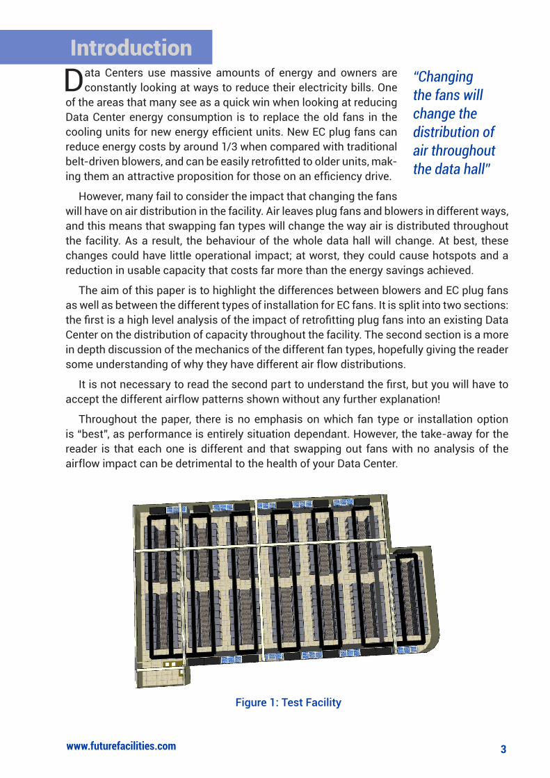
Figure 1: Test Facility
“Changing the fans will change the distribution of air throughout the data hall”
4www.futurefacilities.com
The following section looks at a hypothetical Data Center that has been running for a number of years. The facility is approximately 625m², with over 200 cabinets and a
total cooling capacity of 900kW at N+2 redundancy.
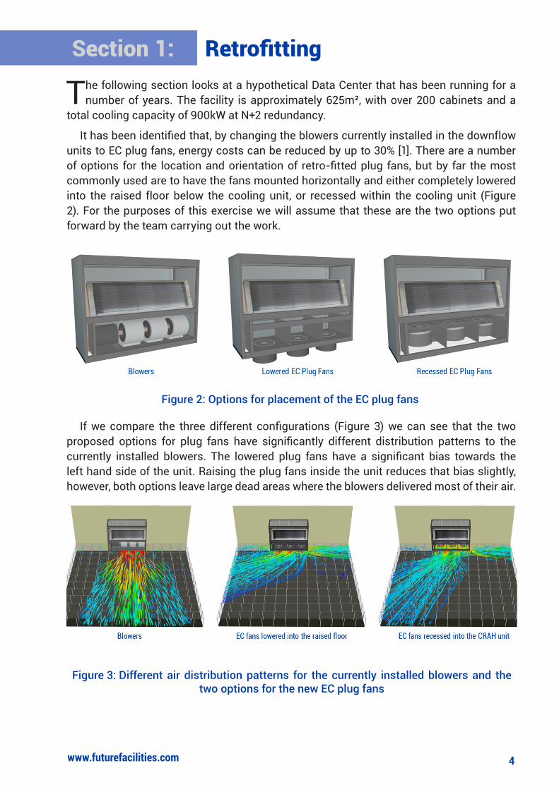
It has been identified that, by changing the blowers currently installed in the downflow units to EC plug fans, energy costs can be reduced by up to 30% [1]. There are a number of options for the location and orientation of retro-fitted plug fans, but by far the most commonly used are to have the fans mounted horizontally and either completely lowered into the raised floor below the cooling unit, or recessed within the cooling unit (Figure 2). For the purposes of this exercise we will assume that these are the two options put forward by the team carrying out the work.
If we compare the three different configurations (Figure 3) we can see that the two proposed options for plug fans have significantly different distribution patterns to the currently installed blowers. The lowered plug fans have a significant bias towards the left hand side of the unit. Raising the plug fans inside the unit reduces that bias slightly, however, both options leave large dead areas where the blowers delivered most of their air.
Section 1: Retrofitting
Figure 2: Options for placement of the EC plug fans
Figure 3: Different air distribution patterns for the currently installed blowers and the two options for the new EC plug fans
5www.futurefacilities.com
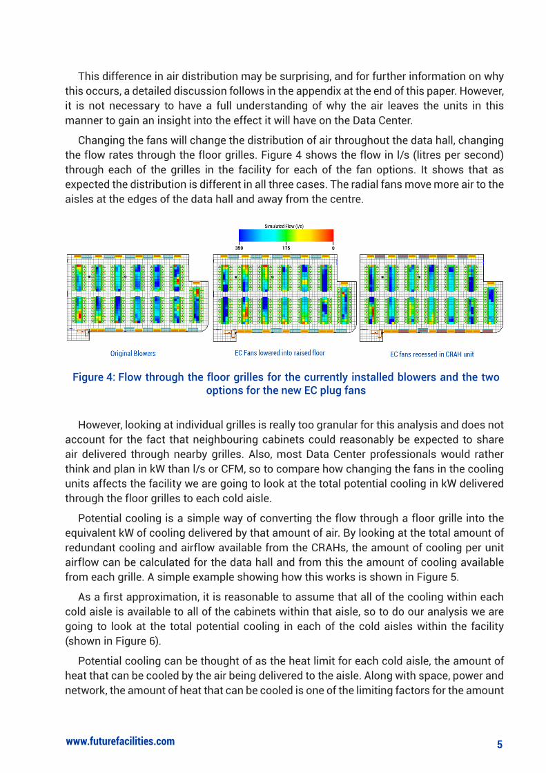
This difference in air distribution may be surprising, and for further information on why this occurs, a detailed discussion follows in the appendix at the end of this paper. However, it is not necessary to have a full understanding of why the air leaves the units in this manner to gain an insight into the effect it will have on the Data Center.
Changing the fans will change the distribution of air throughout the data hall, changing the flow rates through the floor grilles. Figure 4 shows the flow in l/s (litres per second) through each of the grilles in the facility for each of the fan options. It shows that as expected the distribution is different in all three cases. The radial fans move more air to the aisles at the edges of the data hall and away from the centre.
However, looking at individual grilles is really too granular for this analysis and does not account for the fact that neighbouring cabinets could reasonably be expected to share air delivered through nearby grilles. Also, most Data Center professionals would rather think and plan in kW than l/s or CFM, so to compare how changing the fans in the cooling units affects the facility we are going to look at the total potential cooling in kW delivered through the floor grilles to each cold aisle.
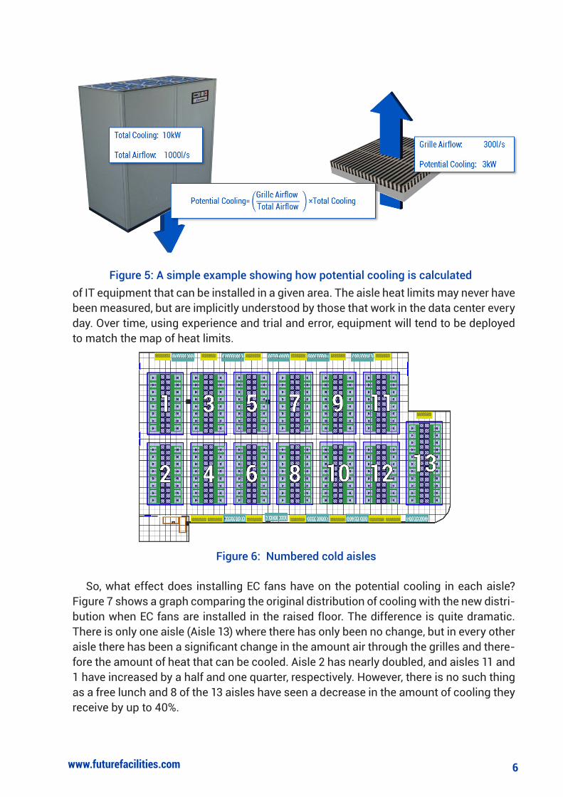
Potential cooling is a simple way of converting the flow through a floor grille into the equivalent kW of cooling delivered by that amount of air. By looking at the total amount of redundant cooling and airflow available from the CRAHs, the amount of cooling per unit airflow can be calculated for the data hall and from this the amount of cooling available from each grille. A simple example showing how this works is shown in Figure 5.
As a first approximation, it is reasonable to assume that all of the cooling within each cold aisle is available to all of the cabinets within that aisle, so to do our analysis we are going to look at the total potential cooling in each of the cold aisles within the facility (shown in Figure 6).
Potential cooling can be thought of as the heat limit for each cold aisle, the amount of heat that can be cooled by the air being delivered to the aisle. Along with space, power and network, the amount of heat that can be cooled is one of the limiting factors for the amount
Figure 4: Flow through the floor grilles for the currently installed blowers and the two options for the new EC plug fans
6www.futurefacilities.com
of IT equipment that can be installed in a given area. The aisle heat limits may never have been measured, but are implicitly understood by those that work in the data center every day. Over time, using experience and trial and error, equipment will tend to be deployed to match the map of heat limits.
So, what effect does installing EC fans have on the potential cooling in each aisle? Figure 7 shows a graph comparing the original distribution of cooling with the new distri-bution when EC fans are installed in the raised floor. The difference is quite dramatic. There is only one aisle (Aisle 13) where there has only been no change, but in every other aisle there has been a significant change in the amount air through the grilles and there-fore the amount of heat that can be cooled. Aisle 2 has nearly doubled, and aisles 11 and 1 have increased by a half and one quarter, respectively. However, there is no such thing as a free lunch and 8 of the 13 aisles have seen a decrease in the amount of cooling they receive by up to 40%.
Figure 6: Numbered cold aisles
Figure 5: A simple example showing how potential cooling is calculated

7www.futurefacilities.com
0
10
20
30
40
50
60
70
80
90
100
1 2 3 4 5 6 7 8 9 10 11 12 13
Pote
ntia
l Coo
ling
(kW
)
Cold Aisle
Original Blowers EC Fans lowered into raised floor
0
10
20
30
40
50
60
70
80
90
100
1 2 3 4 5 6 7 8 9 10 11 12 13
Pote
ntia
l Coo
ling
(kW
)
Cold Aisle
Original Blowers EC Fans recessed inside CRAH
Figure 8: Comparison of the potential cooling available in each cold aisle in the original fan configuration and the with recessed EC fans.
Figure 7: Comparison of the potential cooling available in each cold aisle in the original fan configuration and the with lowered EC fans.
8www.futurefacilities.com
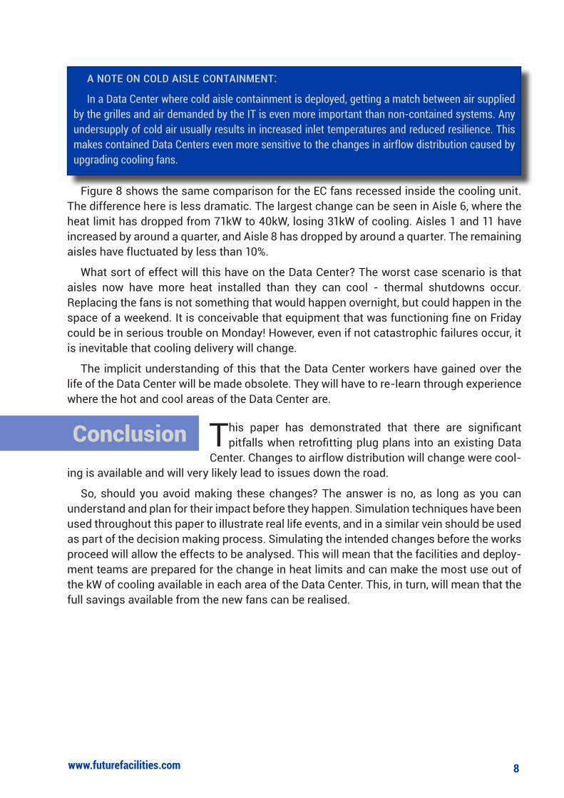
Figure 8 shows the same comparison for the EC fans recessed inside the cooling unit. The difference here is less dramatic. The largest change can be seen in Aisle 6, where the heat limit has dropped from 71kW to 40kW, losing 31kW of cooling. Aisles 1 and 11 have increased by around a quarter, and Aisle 8 has dropped by around a quarter. The remaining aisles have fluctuated by less than 10%.
What sort of effect will this have on the Data Center? The worst case scenario is that aisles now have more heat installed than they can cool - thermal shutdowns occur. Replacing the fans is not something that would happen overnight, but could happen in the space of a weekend. It is conceivable that equipment that was functioning fine on Friday could be in serious trouble on Monday! However, even if not catastrophic failures occur, it is inevitable that cooling delivery will change.
The implicit understanding of this that the Data Center workers have gained over the life of the Data Center will be made obsolete. They will have to re-learn through experience where the hot and cool areas of the Data Center are.
This paper has demonstrated that there are significant pitfalls when retrofitting plug plans into an existing Data
Center. Changes to airflow distribution will change were cool-ing is available and will very likely lead to issues down the road.
So, should you avoid making these changes? The answer is no, as long as you can understand and plan for their impact before they happen. Simulation techniques have been used throughout this paper to illustrate real life events, and in a similar vein should be used as part of the decision making process. Simulating the intended changes before the works proceed will allow the effects to be analysed. This will mean that the facilities and deploy-ment teams are prepared for the change in heat limits and can make the most use out of the kW of cooling available in each area of the Data Center. This, in turn, will mean that the full savings available from the new fans can be realised.
Conclusion
A note on cold Aisle contAinment:In a Data Center where cold aisle containment is deployed, getting a match between air supplied
by the grilles and air demanded by the IT is even more important than non-contained systems. Any undersupply of cold air usually results in increased inlet temperatures and reduced resilience. This makes contained Data Centers even more sensitive to the changes in airflow distribution caused by upgrading cooling fans.
9www.futurefacilities.com
Summary
References
How To Find Out More
Retrofitting EC plug fans in existing Data Centers will reduce the energy required to run the cooling system
The fans in the cooling units are the devices by which the cooling is distributed around the facility
Changing the fans in the cooling units will change the distribution of cooling throughout the Data Center
The only way to prepare for this change is to simulate the new fan arrangement before it is installed
[1] Emerson Network Power, “Technical Note: Using EC Plug Fans to Improve Efficiency of Chilled Water Cooling Systems in Large Datacentres”, Columbus, 2008.
If you have any questions on the issues raised in this paper you can contact the author:
David King, Senior Consultant Engineer, Future Facilities Ltd.
+44 (0) 207 840 9540
Or for more information on Data Center simulation, visit www.futurefacilities.com where you can find more white papers and case studies.
10www.futurefacilities.com
Section 2: Technical Discussion on the Airflow Pattern of Different Fan Types
The first section of this paper looked at the effect of retrofitting different types of fans into an exisitng Data Center. The changes observed were driven by the fact that the
two fan types, blowers and radial fans, have surprisingly different distribution patterns. The following section should give a simple explanation as to why these patterns arise.
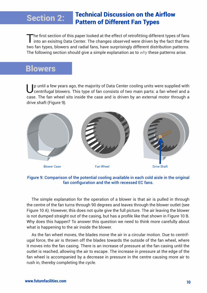
Up until a few years ago, the majority of Data Center cooling units were supplied with centrifugal blowers. This type of fan consists of two main parts: a fan wheel and a
case. The fan wheel sits inside the case and is driven by an external motor through a drive shaft (Figure 9).
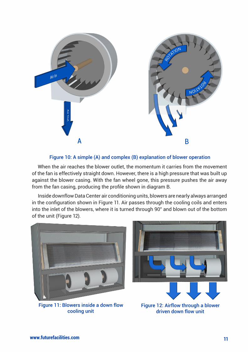
The simple explanation for the operation of a blower is that air is pulled in through the centre of the fan turns through 90 degrees and leaves through the blower outlet (see Figure 10 A). However, this does not quite give the full picture. The air leaving the blower is not dumped straight out of the casing, but has a profile like that shown in Figure 10 B. Why does this happen? To answer this question we need to think more carefully about what is happening to the air inside the blower.
As the fan wheel moves, the blades move the air in a circular motion. Due to centrif-ugal force, the air is thrown off the blades towards the outside of the fan wheel, where it moves into the fan casing. There is an increase of pressure at the fan casing until the outlet is reached, allowing the air to escape. The increase in pressure at the edge of the fan wheel is accompanied by a decrease in pressure in the centre causing more air to rush in, thereby completing the cycle.
Blowers
Figure 9: Comparison of the potential cooling available in each cold aisle in the original fan configuration and the with recessed EC fans.
11www.futurefacilities.com
When the air reaches the blower outlet, the momentum it carries from the movement of the fan is effectively straight down. However, there is a high pressure that was built up against the blower casing. With the fan wheel gone, this pressure pushes the air away from the fan casing, producing the profile shown in diagram B.
Inside downflow Data Center air conditioning units, blowers are nearly always arranged in the configuration shown in Figure 11. Air passes through the cooling coils and enters into the inlet of the blowers, where it is turned through 90° and blown out of the bottom of the unit (Figure 12).
Figure 12: Airflow through a blower driven down flow unit
Figure 11: Blowers inside a down flow cooling unit
Figure 10: A simple (A) and complex (B) explanation of blower operation

12www.futurefacilities.com
We saw previously that the air leaving the blower does have some forward motion, but this will not be enough to turn the air in the space between the false floor and the slab - it will hit the slab. When this collision occurs, the air will spread out with the majority heading forwards out into the facility, but some will head backwards towards the wall (Figure 13).
In fact, Figure 13 is a cross section considering only two dimensions, when the air hits the slab it actually sprays out in all directions (but with a bias towards the front because of the profile created by the blower). This has two consequences:
1) At the edges, air spreads out to the side as it moves away from the unit.
2) Where two blowers are next two eachother, the spreading air combines, speeding up and creating a jet-like effect.
So, the profile of the air leaving the downflow unit is in a block which is wider than the area of the fans and moving directly forward from the unit. The air in the centre of this block is
moving faster than that at the edges, with the fastest moving air being in the gaps between blowers (Figure 14).
Figure 13: Section view of air leaving a blower driven downflow unit
Figure 14: Top down view of airflow leaving a blower driven downflow unit. The air stream is
coloured by velocity.

13www.futurefacilities.com
Gradually, blowers have been replaced by EC plug fans. The EC stands for Electronically Commutated and re-
fers to the way in which the motor powers the fan. EC mo-tors have very significant advantages in terms of efficiency when compared with tradi-tional DC motors and it is this that has driven their uptake in the Data Center market. Also, the removal of the casing means that it takes less energy to prduce the same air flow rate because there is less resistance. However, they do distribute air differently to the tradi-tional blower.
The simple explanation for how the plug fan works is that air is pulled in through the centre of the fan and leaves from all sides (like the blower but without the casing). However, just as the air leaving the blower had a curved profile, so the air leaves the radial fan at an angle.
As the fan rotates, the blades push the air in a circular motion. The centrifugal force means that the air moves to the outside of the blades and falls off the fan into the surrounding area. Air falling off the fan generates a low pressure area in the centre, sucking more air in and the cycle starts again (Figures 15 and 16).
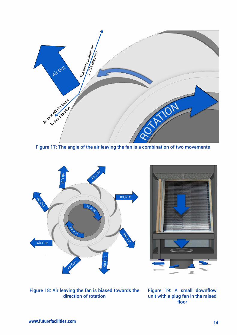
Looking at what happens at the edge of the blade more closely (Figure 17), we can see that as the air falls off the blade, it is moving in the direction of the blade edge. However, because the fan is rotating, it is also being thrown in the direction of the rotation. This means that the direction in which the air leaves the fan is going to be a combination of these two movements, although it is likely to be biased towards the forward motion of the rotation. It is this effect that means that, rather than air coming out at right angles to the edge of the fan, it actually leaves at an angle biased towards the direction of rotation as show in Figure 18.
Unlike the blower, which pulls in air horizon-tally and blows it out vertically, the plug fan pulls in air vertically and blows it out horizontally. This is an important difference because the distribu-tion of the air leaving the unit will be dependent on objects located around the fan in the hori-zontal plane, rather than the vertical plane. The number of objects in the horizontal plane will be
Figure 15: A simple visualisation of the airflow pattern of a plug fan
Figure 16: Air falls off the blades towards the outside of the fan
EC Plug Fans
14www.futurefacilities.com
Figure 17: The angle of the air leaving the fan is a combination of two movements
Figure 18: Air leaving the fan is biased towards the direction of rotation
Figure 19: A small downflow unit with a plug fan in the raised
floor
15www.futurefacilities.com
higher than the vertical, which is typically just the floor slab, so the distribution will be far more installation- and unit-dependant. This makes our analysis of what happens slightly more difficult, so we will consider a small downflow unit with a single fan (Figure 19).
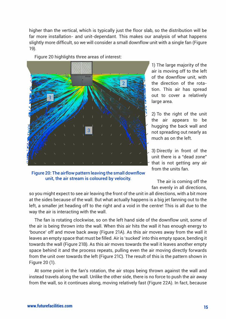
Figure 20 highlights three areas of interest:
1) The large majority of the air is moving off to the left of the downflow unit, with the direction of the rota-tion. This air has spread out to cover a relatively large area.
2) To the right of the unit the air appears to be hugging the back wall and not spreading out nearly as much as on the left.
3) Directly in front of the unit there is a “dead zone” that is not getting any air from the units fan.
The air is coming off the fan evenly in all directions,
so you might expect to see air leaving the front of the unit in all directions, with a bit more at the sides because of the wall. But what actually happens is a big jet fanning out to the left, a smaller jet heading off to the right and a void in the centre! This is all due to the way the air is interacting with the wall.
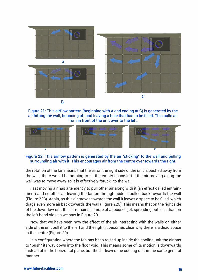
The fan is rotating clockwise, so on the left hand side of the downflow unit, some of the air is being thrown into the wall. When this air hits the wall it has enough energy to ‘bounce’ off and move back away (Figure 21A). As this air moves away from the wall it leaves an empty space that must be filled. Air is ‘sucked’ into this empty space, bending it towards the wall (Figure 21B). As this air moves towards the wall it leaves another empty space behind it and the process repeats, pulling even the air moving directly forwards from the unit over towards the left (Figure 21C). The result of this is the pattern shown in Figure 20 (1).
At some point in the fan’s rotation, the air stops being thrown against the wall and instead travels along the wall. Unlike the other side, there is no force to push the air away from the wall, so it continues along, moving relatively fast (Figure 22A). In fact, because
Figure 20: The airflow pattern leaving the small downflow unit, the air stream is coloured by velocity.
16www.futurefacilities.com
the rotation of the fan means that the air on the right side of the unit is pushed away from the wall, there would be nothing to fill the empty space left if the air moving along the wall was to move away so it is effectively “stuck” to the wall.
Fast moving air has a tendency to pull other air along with it (an effect called entrain-ment) and so other air leaving the fan on the right side is pulled back towards the wall (Figure 22B). Again, as this air moves towards the wall it leaves a space to be filled, which drags even more air back towards the wall (Figure 22C). This means that on the right side of the downflow unit the air remains in more of a focused jet, spreading out less than on the left hand side as we saw in Figure 20.
Now that we have seen how the effect of the air interacting with the walls on either side of the unit pull it to the left and the right, it becomes clear why there is a dead space in the centre (Figure 20).
In a configuration where the fan has been raised up inside the cooling unit the air has to “push” its way down into the floor void. This means some of its motion is downwards instead of in the horizontal plane, but the air leaves the cooling unit in the same general manner.
Figure 21: This airflow pattern (beginning with A and ending at C) is generated by the air hitting the wall, bouncing off and leaving a hole that has to be filled. This pulls air
from in front of the unit over to the left.
Figure 22: This airflow pattern is generated by the air “sticking” to the wall and pulling surrounding air with it. This encourages air from the centre over towards the right.

Adding more fans and underfloor obstructions, and moving the cooling unit away from the wall, will all change the distibution pattern of the air in the floor void. Indeed, the distribution pattern will be be very spcific to each Data Center. Even with this in mind, this discussion has hopefully given you some understanding of how the different fan types distribute air, and why they are different.
Knowing that the fans throw air out in fundamentally different fashions should also help you to understand why retrofitting EC fans in your Data Center will change the way it behaves. This is not to say that either fan type is “better” than the other from an airflow perspective, but that the decision to make the change should not be made without under-standing the effect it will have on the Data Center.
Future Facilities is a privately-owned company formed in 2004 with a
simple mission: to ensure every Data Center can be a model datacenter. One where risk is mitigated and energy efficiency maximised – while both capital and operational costs are reduced to the absolute mini-mum.
Our senior team boasts several acknowledged experts in the design and application of computational fluid dynamics (CFD) software for the Data Center industry. And in June 2006, after two and a half years of painstaking R&D, we launched 6SigmaDC – a suite of integrated software products that tackles head-on the challenges of Data Center lifecycle engineering through the Virtual Facility (VF).
About Future Facilities
• UK Corporate Headquarters
Future Facilities Limited.
1 Salamanca Street
London
SE1 7HX
Tel: +44 (0) 20 7840 9540
Fax: +44 (0) 20 7091 7171
Email: [email protected]
Support: [email protected]
• North America
Future Facilities Inc.
2055 Gateway Place, Suite 110
San Jose
CA 95110
Tel: +1 408 436 7701
Fax: +1 408 436 7705
Email: [email protected]
Support: [email protected]
• Japan
Future Facilities KK
S2 bldg. 5F
2-15-22 Shinjuku
Shinjuku-Ku, Tokyo 160-0022
Tel: +81 (0) 3 5312 8070
Fax: +81 (0) 3 5312 8071
Email: [email protected]
Support: [email protected]
Web: www.futurefacilities.jp