return on investment in simulink for electronic system design
TRANSCRIPT

IBS
RETURN ON INVESTMENT IN SIMULINK® FOR ELECTRONIC SYSTEM DESIGN
International Business Strategies, Inc. 632 Industrial Way • Los Gatos, CA 95030 • USA • Phone (408) 395-9585 • Fax (408) 395-5389

ROI of Simulink - PAGE 2
NOTICE International Business Strategies has given exclusive rights to The MathWorks, Inc. to reproduce and redistribute the report entitled “Return on Investment in Simulink for Electronic System Design”.
© 2005 by International Business Strategies, Inc.

ROI of Simulink - PAGE 3
About the author: Dr. Handel Jones is the founder and CEO of International Business Strategies, Inc., a consulting company with major systems and semiconductor clients around the world, including the U.S., Europe, Japan, S. Korea, and Taiwan. Dr. Jones has more than 35 years of experience in the electronics industry, having served in senior management positions at ITT and at Rockwell International as Vice President of Strategic Planning, Acquisitions, International Marketing, and Engineering. He was responsible for more than 1,500 engineers involved in communications, avionics, and semiconductors.

ROI of Simulink - PAGE 4
IBS EXECUTIVE SUMMARY The topic of this study is how communication and digital entertainment technology companies are realizing a return on investment (ROI) by incorporating the Simulink family of products into their electronic system design flow.
To understand design challenges in these industries, we interviewed several global companies that are implementing these complex systems using advanced integrated circuits (ICs) and embedded software, and measured the impact of Simulink in addressing these challenges.
Responses revealed that designs are becoming more complex while product life cycles are shortening. By developing case studies to provide quantitative metrics on design implementation costs, we proved that vendors can address these challenges by incorporating Simulink and other MathWorks products into their design flow.
Interview responses from engineers clearly demonstrated that the Simulink product family offers essential capabilities for implementing systems with complex IC designs. Simulink also enables teams to bring new designs to the market on time and in specification, which is critical to the financial viability of projects within these fast-moving market segments. We quantified ROI and found it stemmed from improvements in the efficiency of design engineers as well as the impact on product life cycle costs.
Contents of the remaining sections, which support this summary, are:
1. Background to design issues pages 5 to 10
2. Case study highlights pages 11 to 15
3. Conclusions page 16
Appendix A: Source material from the five case study interviews pages 17 to 49

ROI of Simulink - PAGE 5
IBS 1. BACKGROUND TO DESIGN ISSUES Design implementation costs are rising with the reduction in feature dimensions and increase in design complexity, which is shown in the following figure.
FIGURE 1.1 Design Implementation Costs
Verification
Architecture
(80M)(40M)(20M)(5M)(2M)
Physical
Validation
Prototype
0
2
4
6
8
10
12
14
16
18
20
22
24
26
0.35µm 0.25µm 0.18µm 0.13µm 90nmFeature
Dimension(Transistor Count)
Cos
t ($M
)
The increase in design costs is due to the impact of increasing design complexity (90nm is shown for 20M gates [80M transistors]) and growth in parasitics with the reduction in operating voltages and increase in design performance.
The increase in design costs, which affects whether additional design engineering resources are needed, requires the IC vendors to establish new design implementation concepts and improve the performance of point tools.
Architecture is an area that is showing a large increase in design implementation costs due to the migration of system-level design concepts to the IC design implementation phase. Tools from The MathWorks are directly targeted at improving the performance of design engineering teams at the architecture level, which is strategically and financially important for the IC vendors. The central platform for system-level design from The MathWorks is the Simulink family of products. Simulink supports system-level concepts like real-time and concurrency. However, use of The MathWorks' MATLAB® family of products is intimately coupled with Simulink, particularly for tasks like system-level verification, and design and analysis of untimed algorithms. For brevity, however, the term Simulink will be used in this report.
ROI of Simulink - PAGE 6
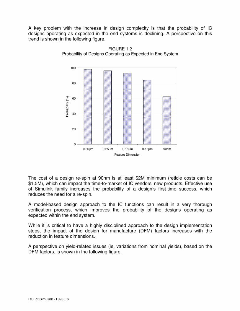
A key problem with the increase in design complexity is that the probability of IC designs operating as expected in the end systems is declining. A perspective on this trend is shown in the following figure.
FIGURE 1.2 Probability of Designs Operating as Expected in End System
0
20
40
60
80
100
0.35µm 0.25µm 0.18µm 0.13µm 90nm
Feature Dimension
Pro
babi
lity
(%)
The cost of a design re-spin at 90nm is at least $2M minimum (reticle costs can be $1.5M), which can impact the time-to-market of IC vendors’ new products. Effective use of Simulink family increases the probability of a design’s first-time success, which reduces the need for a re-spin.
A model-based design approach to the IC functions can result in a very thorough verification process, which improves the probability of the designs operating as expected within the end system.
While it is critical to have a highly disciplined approach to the design implementation steps, the impact of the design for manufacture (DFM) factors increases with the reduction in feature dimensions.
A perspective on yield-related issues (ie, variations from nominal yields), based on the DFM factors, is shown in the following figure.

ROI of Simulink - PAGE 7
FIGURE 1.3 Yield Trends Related to Nominal Yields
0
10
20
30
40
50
60
70
80
90
100
0.35µm 0.25µm 0.18µm 0.13µm 90nm
Feature Dimension
Nom
inal
Yie
lds
(%)
Defect density yields (A)
Lithography-based (B)
Design-based (C)
Process-Related
Design- and Process-Related
The variations of yields from nominal yields (defined as the yield level that is expected based on chip area and defect density levels) are due to reticle- and performance-related factors.
The use of the Simulink family enhanced the analysis of performance-related factors, which are speed- and leakage-based.
Inputs from the companies implementing complex designs are that yields can be increased by 10 to 15 percent for the performance-related factors by effective use of the Simulink family of tools. The increased yields are directly related to product life cycle costs and IC vendors’ profitability. In many cases, yield-related cost factors have a greater impact on an IC vendor’s financial performance than design-related costs (manufacturing costs are five to six times design costs).
A critical requirement for IC vendors is to generate the appropriate product revenues from design-related expenditures.
A perspective on the relationship between design implementation costs and the revenue potential that IC vendors need to obtain is shown in the following figure.

ROI of Simulink - PAGE 8
FIGURE 1.4 Revenue Requirements for Designs
0.0
50.0
100.0
150.0
200.0
250.0
300.0
0.18µm 0.13µm 90nm 0.18µm 0.13µm 90nm
Feature Dimension
Val
ue ($
M)
Design Costs (Hardware)
Revenues at 10x Design Costs
In order for IC vendors to obtain good payback for their design activities, product revenues must be a minimum of ten times design costs, ie, if design costs are $10M, production revenues must be $100M.
Simulink family provides benefits in terms of reducing design implementation costs, improving time-to-market for new designs, and reducing DFM-related manufacturing costs.
The IC industry is going through a phase in which design implementation costs and the risks associated with designs operating as expected are increasing, and production costs can be impacted by DFM-related factors.
The risk/reward environment within the IC industry is changing, and a perspective on these trends is shown in the following figure.

ROI of Simulink - PAGE 9
FIGURE 1.5 IC Industry Operating Environment
Number of Products Risk
Number of ProductsRisk
0.25µm 90nm
High
Low
The 90nm environment is one in which a relatively small number of designs will be implemented, so the revenue per design will need to be high. There can also be a large financial impact from not ensuring strong design performance.
Use of Simulink helps manage design implementation costs and risks and contributes directly to improve profits for the IC vendors and their customer partners.
Another key factor in the profitability of the IC industry is the need to complete new designs on time.
A perspective on the impact of being late to the market based on interviews with a wide range of companies is shown in the following table.
TABLE 1.1 Penalties of Being Late to Market (% Reduction in Product Prices)
3 months 6 months 9 months 12 months
Market characteristics
Fast moving market
Medium moving market
Slow moving market
Fast moving market
Medium moving market
Slow moving market
Fast moving market
Medium moving market
Slow moving market
Fast moving market
Medium moving market
Slow moving market
Revenue reduction due to delays in 14.0 6.6 2.7 21.2 10.1 4.4 27.9 15.5 7.1 35.1 21.0 9.9 introducing new products to market
Opportunity revenue loss from engineers 12.9 12.5 12.1 26.2 25.0 22.4 39.7 37.5 32.3 55.7 50.0 43.6 being unable to work on new products
Subtotal revenue loss 26.9 19.1 14.8 47.4 35.1 26.8 67.6 53.0 39.4 90.8 71.0 53.5
Design engineering cost impact of 5.6 5.2 4.7 11.1 10.3 9.4 16.7 15.5 14.1 22.2 20.6 18.8 delays in design completions

ROI of Simulink - PAGE 10
In fast-moving markets such as wireless handset functionality, wireless networking, digital consumer products, and graphics accelerators, the cost penalties from being three months late to the market with a new product are very high.
While it is important to ensure that designs are completed as scheduled, the need for a re-spin can force IC vendors to accept lower market share and prices for their products due to delays in bringing new products to the market.
The use of Simulink family greatly increases the probability of IC vendors meeting the time-to-market requirements for their products, which can significantly affect their profitability.
With product life cycle metrics becoming more demanding as feature dimensions decrease and designs become more complex, IC vendors are finding that the value of Simulink family is increasing.
While most IC vendors regard Simulink as a way to improve design engineer productivity, in reality the larger benefit is that using it can reduce product life cycle costs and allow IC products that operate as expected in the end systems to be delivered on time. The net impact is improved profits for IC vendors.
ROI of Simulink - PAGE 11
IBS 2. CASE STUDY HIGHLIGHTS Case studies were completed for five leading system and IC vendors that were implementing systems with complex signal processing designs at 0.13µm. The five case studies are considered to be representative of the wireless, consumer (digital entertainment), and physical layer communication applications.
Although these companies had done past designs without using Simulink, all concluded that for complex 0.13µm designs (similar situation applies to 90nm designs), the use of Simulink was critical. The customers provided interview responses that the designs could not have been completed on time, been within engineering cost budgets, or achieved expected chip area and performance characteristics unless Simulink was used.
Consequently, the issue for most companies that are implementing systems with complex 0.13µm and 90nm IC designs is the skill level of their engineers and how extensively they use Simulink, MATLAB, and other tools from The MathWorks.
The financial benefits from using Simulink family was quantified, taking into account the improved design engineering productivity and impact of IC vendors being able to meet their design time-to-market requirements. The analyzed designs were demanding in terms of cost, power, performance, and time-to-market but had high revenue and profit potential for the IC vendors.
0.13µm designs were selected due to the ability to quantify design implementation and product life cycle costs. There are indications that the cost patterns observed at 0.13µm will be replicated at 90nm, with the perspective that the value of Simulink tools will increase as IC designs become more complex.

ROI of Simulink - PAGE 12
The cost benefits of using Simulink products for the case studies are shown in the following table.
TABLE 2.1 Cost Benefits of Using Simulink for Five Case Studies
Case, System type, and IC
characteristics
Cost from specification to
RTL without Simulink ($M)
(estimate)
Cost from specification to RTL with
Simulink ($M) (actual)
Net savings of using Simulink
from specification to
RTL ($M)
Other factors Comments from customers
1) Data Comm Interface 0.13µm 10.9M gates 12.2Mb memory
3.14 1.51 1.63 Total design cost saving (spec to GDSII) estimated at $8.23M with Simulink
Design would not have been completed on time. Savings at system level has 10x impact those at IC level
2) Wireless 0.13µm 8.2M gates 4.5Mb memory
3.70 1.62 2.08 Market value of being early to market was very high
Competitive position in market would be weak without Simulink
3) Wireless a) Baseband IC 0.13µm 8.9M gates 3.6Mb memory b) Transceiver IC
2.46 0.90 1.56 Additional savings from baseband IC (RTL to GDSII tasks) and transceiver IC (Appendix A).
Design could not have been completed on time without Simulink
Simulink was critical in maintaining market share position
4) Video Proc. 0.13µm 9.4M gates 6.1Mb memory
2.96 1.20 1.76 Profit margin for production units increased by 10 to 20 percent because of Simulink
Competitor design that did not use Simulink was six months late
Use of Simulink allowed strong position in market to be established
5) Wireless handheld 0.13µm 7.6M gates 3.8Mb memory
3.10 1.54 1.56 Design worked as expected and did not require re-spin
Market position is strong based on use of Simulink
Without use of The MathWorks’ tools, market position would be weak
The cost benefits of using Simulink family are significant at the IC design level (specification to RTL). While most customers use the design cost benefits to justify the cost of adopting Simulink family, complex designs cannot usually be completed within the expected time window or cost budgets without it. The cost savings shown in column 4 are net savings: they take licensing cost, and other migration costs such as training, into account. Use of Simulink represents a paradigm shift versus older methods so proper training is key.
The customers provided inputs that even if design engineering resources were doubled, designs could not be completed on time without access to Simulink tools. In addition,

ROI of Simulink - PAGE 13
there is a high probability that the designs would have required a re-spin if many of the disciplines required to effectively use Simulink family of products were not used. It was not possible to quantify the impact of the reduced probability of a re-spin, but the IC vendors provided inputs that Simulink family was critical in establishing the front-end methodology in order to efficiently implement other design steps.
Inputs to this study were also provided by IC vendors that did not use Simulink family. Their design implementation times were 18 to 24 months (1.5x longer than if Simulink was used), and one or two re-spins were usually required to meet the performance, power, and chip area metrics (these designs were done in 0.18µm and 0.25µm technologies).
The analysis of design projects and the IC products that have emerged from these projects shows wide variations in the design capabilities of IC vendors. Many of the capabilities are related to the design tools that are used.
Other benefits
Inputs were obtained from IC vendors regarding the characteristics of their designs with and without the use of Simulink. A perspective of the differences is shown in the following table.
TABLE 2.2 Product Comparison Based on Use of Simulink versus Other Approaches
Chip area With Simulink Without Simulink
Chip area (nominal) 100 sq. mm 120 to 130 sq. mm
Chip power (nominal) 100mW 130mW
Product noise levels (nominal) 100dB 150dB
Design implementation costs $8M $10M
Manufacturing costs (per unit) $10.00 $15.00
Selling price (per unit) $18.00 $17.00
Gross margin 44% 12%
The improvements in chip area, chip power, and factors impacting signal-to-noise ratios are related to the ability of engineers to efficiently evaluate trade-offs in parameters.
The result of improved product performance and smaller die area is the increase in gross margin from 12 to 44 percent. With $200M in production revenues, the profit difference for the IC vendor would be $64M. It is, consequently, important to measure the value of Simulink in terms of profit metrics and reduced design implementation costs.

ROI of Simulink - PAGE 14
While top management of IC vendors is trying to reduce design and design tool licensing costs, there is the need to take into account the profit contribution from having leadership design implementation capabilities.
Based on customer inputs, a cost comparison estimate for 0.25µm, 0.18µm, and 0.13µm designs with and without the use of Simulink family is shown in the following table.
TABLE 2.3 Cost Comparison Based on Use of Simulink versus Other Approaches
Cost of design at 0.25µm ($M) Cost of design at 0.18µm ($M) Cost of design at 0.13µm ($M)
With Simulink
Without Simulink
Difference
With Simulink
Without Simulink
Difference
With Simulink
Without Simulink
Difference
5m gates 7.4 11.1 3.7 6.3 9.7 3.4 5.8 9.3 3.5
10m gates NA NA NA 14.1 22.3 8.2 13.5 26.2 12.7
20m gates NA NA NA 19.7 32.4 12.7 18.4 40.9 22.5
Note: Based on extrapolation of customer inputs.
The data shown is based on the case studies and additional information obtained from other IC vendors. It illustrates the savings from the use of Simulink versus two design parameters (the migration to smaller feature dimensions and the increasing complexity of designs). The analysis shows that the cost advantages of using Simulink family increase as feature dimensions decrease and designs become more complex. This trend is consistent with the capabilities that are built into Simulink.
In addition to the increasing cost savings with increasing complexity, the use of Simulink by the design team also reduces manufacturing costs, which are shown in the following table.
TABLE 2.4 Cost Benefits of Using Simulink (0.13µm Design)
Design cost impact Manufacturing cost impact
Design
characteristic
Design implement-ation ($M)
Savings from using
Simulink (%)
Cost savings
($M)
Design implement-ation ($M)
Savings from using
Simulink (%)
Cost savings
($M)
Design cost impact
• 400MHz/4M gates
• 800MHz/6M gates
• 1.3GHz/8M gates
3.6
6.3
12.3
7.0
11.6
18.1
0.252
0.712
2.25
75
84
103
3.1
6.8
16.2
2.32
5.71
16.69
ROI of Simulink - PAGE 15
The analysis of interview responses shows (even after normalization over complexity and revenues) that as design performance increases at 0.13µm, the benefits of Simulink increase. The benefits from using the Simulink platform increase as feature dimensions decrease, as design complexity increases, and as performance requirements become more stringent.
While the engineers of IC vendors that are implementing complex designs are convinced of the technical value of Simulink, the top management of IC vendors and systems companies still need to understand the financial value of the tools (ie, profit impact), especially in environments where pressures to reduce costs are strong.
The most important metrics for using Simulink-based design flow are related to IC product life cycle costs and the ability of IC vendors to establish strong market positions by completing their designs on time.
The resulting improvement in the profits of IC vendors represents the driver for effective and extensive use of Simulink family.

ROI of Simulink - PAGE 16
IBS 3. CONCLUSIONS The interview responses from many engineers at a wide range of companies are that Simulink family represents essential capabilities for implementing complex IC designs. While there are significant technical benefits from Simulink, its ability to assist teams in bringing new designs to the market on time is critical to the financial viability of IC vendors within fast-moving market segments.
A number of IC vendors that are participating in data communications, wireless communications, multimedia consumer applications, etc, have provided inputs that without the use of Simulink family, IC designs could not be completed on time and their competitive positions would weaken.
End-market segments such as wireless communications, wireline communications, consumer products, and computer peripheral products have intense time-to-market pressures (new products need to be developed in six to twelve months). Product and equipment lifetimes can also be six to twelve months, which means that being late to the market can preclude an IC vendor from participating in that market segment.
IC vendors and system companies that are using Simulink, etc, relate the capabilities of the tools to improved design engineering productivity (a must-have tool for design engineers).
These case studies demonstrate that the profitability of these IC vendors can be improved with more effective use of Simulink. The profit metric provides the real financial benefits to IC vendors.
IC vendors that do not use Simulink, etc, or have little expertise in using it, can increase their competitiveness by improving their skill base with training and use of the tools.
Many IC vendors are already using Simulink, but the strategic benefits are not well-understood by the IC vendors’ top management. The case studies show that management's analysis of the benefits of Simulink family need to be extended to quantify profit opportunities (performance and manufacturing cost benefits) for the IC vendors in addition to design cost reductions metrics that are already used.

ROI of Simulink - PAGE 17
APPENDIX A: SOURCE MATERIAL FROM THE FIVE CASE STUDY INTERVIEWS

ROI of Simulink - PAGE 18
IBS APPENDIX A: Source Material from the Case Study Interviews Customers were interviewed to obtain inputs on the benefits of Simulink.
The costs and risks of implementing IC designs are rising with the increasing complexity of designs, especially for mixed-signal ICs. At the same time, product life cycles are getting shorter. Several competences impact cost and risk:
� Functional verification
� Physical design steps
� Ability to develop the RTL-level database from the specification
The MathWorks’ tools mainly impact the latter, so this was explored in depth in the interviews.
The customer interviews provide visibility into the design-related problems experienced. The emphasis was on the mixed-signal, signal-processing (DSP-based), and communication physical layer segments of the electronics industry. There was also an emphasis on the larger companies to explore the impact of The MathWorks’ tools on production volumes and to afford comparison with previous design flows.
The interview process was interactive, and the targeted companies participated in multiple discussions. Customers agreed to share data on condition of anonymity. The following case studies use a common format (based on common themes which emerged during the interviews).

ROI of Simulink - PAGE 19
A.1 INTERVIEW NO. 1: DATA COMMUNICATIONS COMPANY (PROGRAM MANAGER)
IBS A.1.1 PERSPECTIVE: TOP-LEVEL ISSUES FOR DESIGN The customer inputs are the following:
� The company is a systems organization that develops full custom ICs and standard cell ASICs. for high-end data communications systems. It is a technology and market share leader. Its engineers are very experienced and highly trained in system and IC design.
� Architectural concepts need to be developed and translated into the system and IC designs. The MathWorks’ model-based design approach was selected as an efficient method for initial design implementation designs and reuse of IP. The high level of abstraction possible with The MathWorks’ tools was considered a key attribute.
� Various types of architecture options for the control systems need to be evaluated, with the following major building blocks:
� Processor engines. The Power series architecture has communications-centric interfaces and is the preferred choice, but other options need to be evaluated.�
� Memory. Multiple blocks, ie, discrete and embedded, are used on the various boards. The performance and density of the memory blocks varies greatly, and fast cycle memories have been used extensively.
� FPGAs. Four or eight FPGAs are used for the control architecture, and a number of network interface boards have programmable logic because of the need to modify functionality in the field.
� Interface functions. Some interface functions can be integrated with FPGAs, but a wide range of interface types are used, ie, SERDES, 10Gb/s Ethernet, etc. Interface functions represent major design and system verification challenges.
� Hardware development is secondary to software development, which has already taken place (70 percent of new system development costs are for incremental software development, while 30 percent are for new hardware development: The software base that has been developed over a number of years needs to be maintained, with the goal of minimizing the software risks. Hardware must conform to software.)
The complexity of new system designs is increasing rapidly (5x to 10x for each generation), and it is critical to have reusable functional blocks (applies to software as well as hardware).

ROI of Simulink - PAGE 20
IBS A.1.2 DESIGN FACTORS The issues regarding the design factors include the following:
� There are multiple design teams in various geographic locations, with the architecture group in a central location to coordinate design activities and integrate the functional blocks. The design teams that are located in multiple geographic regions need to have high levels of autonomy.
� Models are developed that are portable and very accurate. The model development phase must be factored into the total design cost and implementation times.
� ICs must interface with each other, as do the boards. The systems have many boards, with new boards (interface cards) constantly being developed.
� Variants of SPICE are used, but simulation time is long, and there are not enough simulations to ensure thoroughness and accuracy of the data. Simulink is 100x faster than SPICE-based tools, which saves cost. The use of Simulink increases the probability of designs operating as expected after the prototypes are received.
� Specifications for IC designs continue to change until timing closure. The abilities to modify and thoroughly document design databases are necessary. The interface between SPICE and Verilog is always very time-consuming and requires the use of trained engineers. Interfaces for the blocks within IC chips, chip-to-chip, board-to-board, etc, need to be developed. Signal chains in systems are complex and need an efficient approach to partitioning. As an alternate to SPICE and Verilog co-simulation, MATLAB and Simulink provide a simulation environment with higher-level capabilities, where partitioning of the key functional blocks can be performed effectively. SPICE etc. are not effective during the design phase, but are needed for the accuracy during subsequent verification.

ROI of Simulink - PAGE 21
IBS A.1.3 APPROACHES The approaches include the following:
� The top-down approach mandated the ability to model and simulate analog, mixed-signal, and digital functions with a common database. A high-level simulation environment was mandatory.
� Simulation times had to be measured in minutes rather than in days so that simulation could be done almost in real time. The data obtained during the simulation phase also had to be in a format that was easy to interpret.
� High computing power is available and use of this capability is important. Computing power costs are less than 5 percent of design implementation costs, and it is not appropriate to try to save money on computing power (computer systems are networked, local as well as centralized compute power being provided).
� Virtuoso was used for the physical design steps for analog and mixed-signal blocks, and the expertise of design engineers in this arena is strong.
� The technology for digital 0.13µm and mixed-signal 0.13µm and 0.18µm designs are mature. Mixed-signal technology 0.13µm has difficulties due to the deterioration of analog function performance with the reduction in operating voltages.
Structured design approaches are required that allow reuse of blocks and finished designs.

ROI of Simulink - PAGE 22
IBS A.1.4 WHAT HAS BEEN ACHIEVED The achievements include the following:
� The system has been brought to the market, and utilized successfully in a range of operating environments.
� The system operates as expected and has upside performance potential. The system’s lifetime is expected to be at least seven years, including a planned upgrade of the hardware and software in the future.
� The system is partitioned into racks, cards, and ICs (cards and racks are changed between various systems), including ASICs, with many high-speed interfaces. The system is hierarchical and modular, and enhancements can be made.
� A valuable characteristic of Simulink is that is has enabled reuse of IP and functional blocks. It is a key tool for characterization, simulation, etc, and provides high levels of verification as well as a good documentation structure.
� The design teams, which are in multiple locations, can access the databases on specific blocks as well as the total system (authorization control is implemented). The ability to have design teams work on various segments of the design is a key requirement.
� The high-speed mixed-signal blocks (SERDES, etc) have been fully verified, characterized, are reusable, and operated as expected (the company and its design partners have major strengths in mixed-signal interfaces). Simulink is a major capability in this arena.
Although cost is important, both time-to-market and the ability to ensure that the system operates as expected are critical.
Controlling costs is essential, as is ensuring that the hardware operates as expected (according to the program manager of a complex system). With 200 engineers developing software, a three-month delay in hardware design has a cost impact of $12.5M and a loss of revenues that can total hundreds of millions of dollars.

ROI of Simulink - PAGE 23
IBS A.1.5 COST METRICS The total system design cost is more than $300M, of which software is 70+ percent. The hardware design cost is approximately $70M.
The core ASIC complexity is 10.9M gates and 12.2Mb of memory, and the technology is 0.13µm.
A break down of the actual design costs is shown in the following table.
TABLE A.1.1 0.13µm Design Cost Metrics With Simulink
(Communications Interface)
No. of Time (in Annual cost per Task engineers weeks)* No. % total engineer ($K) ($M) % total
Specification to RTL • Project team engineers 12 28 336 16.3 215 1.39 16.6
• Additional engineers 2 14 28 1.4 220 0.12 1.4
RTL to netlist • Project team engineers 24 42 1,008 49.0 207 4.01 48.1
• Additional engineers 10 21 210 10.2 219 0.88 10.6
Netlist to GDSII • Project team engineers 16 28 448 21.8 212 1.83 21.9
• Additional engineers 4 7 28 1.4 220 0.12 1.4
TOTAL 68 NA 2,058 100.0 NA 8.35 100.0
Note: * Total reflects linear time.
Total person weeks Project cost
The design engineering head count levels are shown for the project team engineers as well as any additional engineers, ie, experts brought in for portions of the designs.
The design was completed up to GDSII in approximately 60 weeks, which was within three weeks of the expected date, and operated as expected.
Multiple iterations of the specification to RTL phase were done in order to optimize the compromises between performance and power.
An earlier generation of the design was done at 0.18µm without using Simulink. The complexity was lower. Nevertheless, this experience gave an indication of what the project would have cost without Simulink.
A break down of the actual design costs is shown in the following table.

ROI of Simulink - PAGE 24
TABLE A.1.2 0.18µm Design Cost Metrics Without Simulink
(Communications Interface)
No. of Time (in Annual cost per Task engineers weeks)* No. % total engineer ($K) ($M) % total
Specification to RTL 10 42 420 19.3 195 1.58 18.3
RTL to netlist 28 56 1,568 71.9 208 6.27 72.7
Netlist to GDSII 8 24 192 8.8 210 0.78 9.0
TOTAL 46 NA 2,180 100.0 NA 8.62 100.0
Total person weeks Project cost
Note: * Total reflects linear time.
The 0.18µm design done without Simulink had approximately 5M gates of logic and 5Mb of memory. The performance requirements were not extensive, and completion time was 70 weeks.
It is estimated that the 0.13µm design (Table A.1.1) was twice as complex as the 0.18µm design (Table A.1.2).
The inputs indicate that, had the previous 0.18 µm flow (without Simulink) been used, the 0.13µm design would have cost $16.58M instead of the $8.35M shown, and completion time would have been 100+ weeks, which would have resulted in delays in the time-to-market for the system of 40+ weeks.
The savings from using Simulink (and MATLAB) were not only in the specification-to-RTL phase, but in the functional verification steps as well.
Without MATLAB and Simulink, the critical issue is that the 0.13µm design would not have been completed on time, even if the design engineering head count had been doubled. In addition, the uncertainty of the design not operating as expected would have increased. The value at the system level is potentially ten times that at the IC level (with IC at 10 percent of revenues).
The system complexity benefits are difficult to quantify at the IC level. The engineers constantly drive the limits of technology, and if better tools become available, system performance can be enhanced.
The value of Simulink and MATLAB was conservatively estimated by the company in the $10M to $15M range, but direct cost savings alone were approximately $8M based on a previous design done at 0.18µm.
TABLE A.1.3 Design Cost Savings Summary (Communications Interface)
Task Without Simulink ($M) With Simulink ($M) Savings ($M)
Spec to RTL (high confidence) 3.14 1.51 1.63
Spec to GDSII (estimate) 16.58 8.35 8.23

ROI of Simulink - PAGE 25
A.2 INTERVIEW NO. 2: IC VENDOR ACTIVE IN MIXED-SIGNAL DESIGNS WITH DSP ENGINES (ENGINEERING MANAGER)
IBS A.2.1 PERSPECTIVE: TOP-LEVEL ISSUES FOR DESIGN The customer inputs are the following:
� The company is a high-growth IC vendor that drives the limits of IC design and process technology. The company's successful strategy is to be early to the market with its new IC products in order to obtain price premiums and high market share. There are intense pressures on the design engineers.
� IC product design schedules need to be shortened because the time-to-market for new systems has decreased and the requirements for IC functionality have escalated and are becoming increasingly complex. Customers (system companies) want to interface with IC vendors that are early to the market with new IC products that have an increasing level of software content. Old design methods with extensive handcrafting do not work within the present business environment. The use of C has limitations, especially for the designs that need to support real-time and concurrency.
� Most designs are variants of existing designs, and as a result, a high level of reusability for functions or blocks is needed. At any one time, multiple variants of a design form the product line. Also, multiple foundries are used for high-volume products, and data must be transportable between the foundries.
� The key problem areas in terms of time comes from the need to agree on the specification with the systems customer, and then generate the RTL code and net lists for the digital and analog blocks, respectively. The traditional approach was to use SPICE to simulate analog blocks and Verilog for timing analysis, but these were too slow. Variants were tested, and while there was some improvement, they were time-consuming and too engineering-resource-intensive. While SPICE and Verilog can be used for final verification, they were not suitable for design and simulation.
Since there are oftentimes problems with achieving timing closure for designs, the specifications may need to be modified, which means that a new RTL database needs to be generated quickly. The ability to have fast iterations of the design steps is a critical competitive advantage.
� The company needs to train engineers on tools and methodologies that will be used for many generations of designs. The MathWorks’ model-based design approach with the ability to import some legacy C provides a very beneficial operating environment.
Many engineers already have strong signal processing expertise and adapt rapidly to the use of Simulink.
ROI of Simulink - PAGE 26
IBS A.2.2 DESIGN FACTORS The issues regarding the design factors include the following:
� The most complex design done to date was at 0.13µm, which had a multigigahertz radio as well as baseband functionality. Although low power was important, it was also critical to have very low noise (the noise and jitter parameters were considered the most important factors).
Chip area was important as well, and the area required for the mixed-signal functions and interface to the digital blocks had to be small.
� A number of customers were waiting for the prototypes, with potential unit volumes of tens of millions during the first year. The goal was to dominate the market by introducing an integrated CMOS-based solution early on.
� The foundry vendor was qualified and had already run some of the key blocks as IP. The mixed-signal blocks, however, were a challenge, and the process and product engineers were dispatched to the foundry to ensure that process control was within the design requirements.
� The design was an enhancement of a previous 0.18µm design, but with much higher levels of integration. The design also had significant software content (40 to 50 percent of the total design resources were for software), and hardware and software development had to be done concurrently (different locations).
� The design team (which was in multiple locations) was experienced, very skilled (40 percent possessed Ph.Ds), and considered the best in the world.
Nevertheless, the project was considered difficult, and actions were taken to reduce the risks, including additional checking steps. It was agreed that chip area could be increased if there was an increased probability of the design operating as expected in the end system.
� A key problem was determining what would be included in the software and what in hardware. Multiple iterations were required through place-and-route to determine the best trade-off based on chip area, performance, and performance risks.
� Chip area constraints represented a problem with timing closure, showing how important it is to be able to do multiple iterations rapidly (new tools were used for the layout of key blocks).
� The key initial step was to get to the RTL stage so that following chip design steps could be started rapidly.
This project was considered the most important in the company.

ROI of Simulink - PAGE 27
IBS A.2.3 APPROACHES The approaches include the following:
� Models were developed for the major functional blocks and interfaces between the blocks. The interfaces had extensive performance and power requirements, and no other IC vendor globally could implement a design at this level of complexity within the time constraints that were established.
The IC vendor was successful (high revenue growth with profits) because the designs that were done are much more complex than those available from competitors.
� MATLAB and Simulink were selected as the key front-end tools. The requirement was to have an initial pass for the design through initial timing closure to obtain visibility into the problem areas.
Multiple simulations were then done to improve the granularity of the design verification process. Multiple place-and-route iterations were done to obtain an initial estimate of chip area, power, etc.
Without Simulink, the design schedules would not have been competitive.

ROI of Simulink - PAGE 28
IBS A.2.4 WHAT HAS BEEN ACHIEVED The achievements include the following:
� The chip was completed and the original schedule for prototype delivery was met. Customers were satisfied with the prototypes that were provided.
� Simulation of high-frequency, analog, and mixed-signal blocks were done with high levels of precision. The timing requirements were within the design constraints, with high levels of accuracy.
MATLAB and Simulink were critical in achieving the level of precision required for the key building block functions and the design performance. Although other design tools were important, Simulink was the key simulation environment that allowed verification of the design functionality at the top level.
� The design was highly modular so that portions of the design could be enhanced. The enhancements would be done to improve functionality as well as increase yields. The use of the model-based design approach with Simulink enables the functions to be modified rapidly. There is a high level of probability of the functions operating as expected in the end products. A critical requirement, however, is for modifications to the blocks to be verified at the block (model) level as well as in the integrated IC design environment.
A strong market position has been established with the design, and 50+ percent market share has been achieved in a high-growth segment of wireless communications. Cumulative revenues for the design and derivatives are expected to be in excess of $1B over the next few years.

ROI of Simulink - PAGE 29
IBS A.2.5 COST METRICS A break down of the design costs is shown in the following table.
TABLE A.2.1 0.13µm Design Cost Metrics With Simulink
(Wireless)
No. of Time (in Annual cost per Task engineers weeks)* No. % total engineer ($K) ($M) % total
Specification to RTL • Project team engineers 10 26 260 14.9 220 1.10 13.7
• Additional engineers 2 16 32 1.8 350 0.22 2.7
RTL to netlist • Project team engineers 28 39 1,092 62.6 240 5.04 62.8
• Additional engineers 6 20 120 6.9 250 0.58 7.2
Netlist to GDSII • Project team engineers 9 24 216 12.4 235 0.98 12.2
• Additional engineers 2 12 24 1.4 245 0.11 1.4
TOTAL 57 NA 1,744 100.0 NA 8.02 100.0
Note: * Total reflects linear time.
Total person weeks Project cost
The cost of the project was considered consistent with similar designs done by the customer at 0.13µm with the use of The MathWorks’ tools.
A key factor in the project was that the time to design completion was critical, and the customer was able to get the new product to the market on time.
Without the use of Simulink, the customer estimated that 20 to 50 engineers working for 30 to 40 weeks would have been required to complete the task from specification to RTL (costing $3.70M (conservative estimate) instead of $1.32M, ie, saving $2.38M). The total cost of adopting Simulink and MATLAB was estimated at $300K, giving a net savings of $2.08M if 100% of cost is assigned to this project (conservative method because actual residual value was significant)
Additionally, the customer provided qualitative inputs that without access to The MathWorks’ tools, two smaller designs probably would have had to be implemented, which would have increased the system performance risks.
ROI of Simulink - PAGE 30
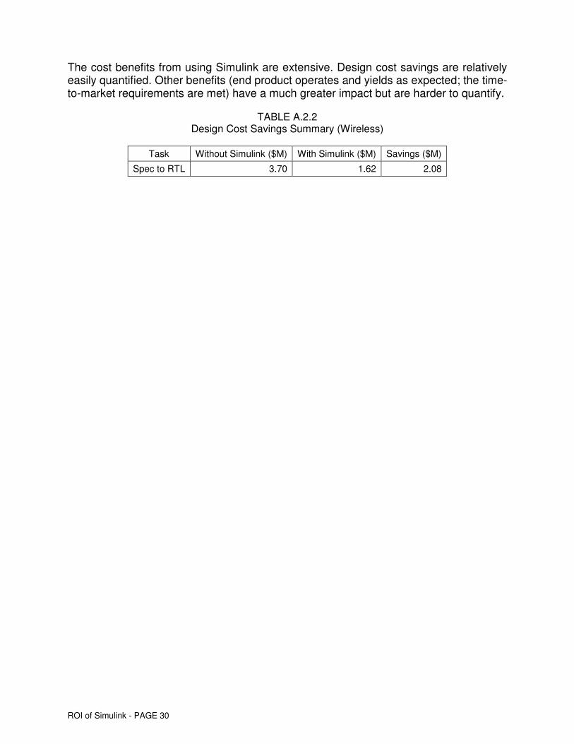
The cost benefits from using Simulink are extensive. Design cost savings are relatively easily quantified. Other benefits (end product operates and yields as expected; the time-to-market requirements are met) have a much greater impact but are harder to quantify.
TABLE A.2.2 Design Cost Savings Summary (Wireless)
Task Without Simulink ($M) With Simulink ($M) Savings ($M)
Spec to RTL 3.70 1.62 2.08
ROI of Simulink - PAGE 31
A.3. INTERVIEW NO. 3: LARGE IC VENDOR ACTIVE IN WIRELESS COMMUNICATIONS (PROJECT MANAGER)
IBS A.3.1 PERSPECTIVE: TOP-LEVEL ISSUES FOR DESIGN The customer inputs are the following:
� The design is for baseband functionality, which includes mixed-signal interfaces. 0.13µm technology, two processor engine cores (a controller (ARM based), and an application co-processor (also ARM based)) were used.
The mixed-signal functions on the baseband need to interface with the transceiver, which was done as a companion design (SiGe-based design).
A chip set approach was taken to ensure that system functionality was optimized, and extensive systems and software development was done by the customer, a systems company in parallel with the IC design, yielding faster time-to-market.
� The total time for the design from initiation to delivery of the prototypes was nine months. It was critical to have a rapid design iteration time from specification to RTL because of the need for early visibility into the functionality and characteristics of the design. �
� Simulink was a critical capability in ensuring that the initial generation of the RTL database was done rapidly. The model-based approach of The MathWorks’ tools was efficient for the early development activities, which included the ability to continue having extensive simulation of difficult functions such as phase-lock loops.�
� The concept of having a modular design approach was considered critical and was well-supported by Simulink. The approach of having high levels of reusability of the IP was important as well.
The design challenges were extensive, but the design team was highly skilled and had experience with this type of design.

ROI of Simulink - PAGE 32
IBS A.3.2 DESIGN FACTORS The issues regarding the design factors include the following:
� Design completion time, from receipt to specification to prototypes, was established at nine months, but it was expected that the specification would be changed a number of times due to the compromises needed between power, cost (chip area), and performance. There was the expectation that compromises would have to be made to ensure that system competitiveness was optimized based on positioning the end products in the market.
� The phase-lock loop design challenges were extensive. Simulink was the main productivity tool for developing the initial product concepts, with tools such as HSIM for verification of the functions.
The mixed-signal functionality of the design represented a major challenge in terms of design performance, power, and cost.
� While the cost of implementing the design was important, the most critical factor was ensuring that it worked first time in silicon and that the time-to-market schedule could be met. A re-spin would seriously delay the shipping of the end product. For example, a three-month delay in shipping the end product could have a 5 to 8 percent market share impact as well as require a price decrease, etc.
� As I/O blocks, digital and mixed-signal had to be integrated within the design. The interface between analog and digital functions has always been a design challenge and is becoming more so with the reduction in feature dimensions.
Simulink was the key tool needed to ensure a full evaluation of the functional blocks and interfaces. Input were that no other tool could have performed as effectively as Simulink.
� The design teams were located in multiple geographic regions, with software and hardware developed concurrently.
� The emphasis of the project team was on the steps between RTL and GDSII (90 percent of the design engineering activities), but the early availability of RTL was a critical factor in the design team’s ability to meet the schedules. The benefits of MATLAB and Simulink extended beyond the spec to RTL generation phase to the entire design process.
The design requirements were extensive, and top management was very involved in the schedule for the design and in ensuring on-time completion.

ROI of Simulink - PAGE 33
IBS A.3.3 APPROACHES The approaches included the following:
� The largest team was focused on the digital baseband design, another was focused on the mixed-signal transceiver design, and third (the smallest) was responsible for the operation of the two chips in the system.
Having behavioral models for the functional blocks and the subsystem enabled good communication between the various design teams and task groups. It also allowed close monitoring of the progress of the design implementation steps.
� The initial goal was to develop an RTL database as quickly as possible so that an initial pass at the design could be done (model-based design).
� A key requirement was to ensure that the mixed-signal blocks, including the phase-lock loops, could be thoroughly verified as discrete functions and for operation within the integrated designs. Phase-lock loops take hours to simulate with SPICE and minutes with Simulink. A key part of the design approach was to develop models for the phase-lock loops in Simulink and obtain insight into the potential problem areas early on. The use of Simulink reduced the time for phase-lock loop simulation and increased accuracy Although time used to be the most important metric, accuracy has become the most important.
� The clock systems were complex, and MATLAB and Simulink allowed multiple clock structures to be utilized. Multiple domain clocks, gated clocks, etc, were used, and a top-down approach to the performance of the clocks was required.
The approach was to rapidly develop an initial RTL database and run the design steps from synthesis to place-and-route in order to obtain an initial estimate of die size, timing closure problems, signal integrity problems, power levels, etc. Each part of the design was then refined to determine how rapidly the design could be improved.

ROI of Simulink - PAGE 34
IBS A.3.4 WHAT HAS BEEN ACHIEVED The achievements include the following:
� Initial systems (10K to 50K) would be shipped with the old transceiver design, but the high-volume production phase (5M to 20M units) could be fulfilled with the new transceiver design.
Without the use of Simulink, it is likely that 1M units would have had to be shipped with the old transceiver design, which would have resulted in large losses (millions of dollars).
� Without Simulink, it is unlikely that schedules could have been met even with the use of additional engineers in the generation of RTL from the specification (highly skilled engineers were not available). The total value of Simulink on the project should be conservatively estimated at $10M+ (also includes the benefit of MATLAB).
Simulink and MATLAB are powerful tools (as are other tools, such as Real-Time Workshop®).

ROI of Simulink - PAGE 35
IBS A.3.5 COST METRICS The value from Simulink on the project is estimated at $10M, based on the customer’s perception of benefits for market participation, etc.
i) Baseband Design
A break down of the design costs is shown in the following table.
TABLE A.3.1 0.13µm Design Cost Metrics With Simulink
(Baseband)
No. of Time (in Annual cost per Task engineers weeks)* No. % total engineer ($K) ($M) % total
Specification to RTL • Project team engineers 8 26 208 7.8 205 0.82 7.2
• Additional engineers 2 10 20 0.7 220 0.08 0.7
RTL to netlist • Project team engineers 52 37 1,924 71.8 225 8.33 72.6
• Additional engineers 10 16 160 6.0 230 0.71 6.2
Netlist to GDSII • Project team engineers 14 24 336 12.5 215 1.39 12.1
• Additional engineers 4 8 32 1.2 225 0.14 1.2
TOTAL 90 NA 2,680 100.0 NA 11.47 100.0
Note: * Total reflects linear time.
Total person weeks Project cost
Without the use of Simulink and MATLAB, it is estimated that the number of engineers from specification to RTL would have been at least 24 to maintain the other head count and time schedules at the levels shown in the table above. The savings with the use of Simulink was $1.56M.
The value of Simulink in the total flow was not quantified. The $1.56M savings during the specification to RTL task is a genuine metric. The customer was unwilling to quantify the additional saving during RTL to GDSII tasks.
Without the use of Simulink, the probability of the design operating as expected (even with the use of 24 engineers from specification to RTL) would have declined from the expected 90+ percent to the 50 to 60+ percent level. The impact on the project from being late could have been tens of millions of dollars in lost profits.
Without Simulink, migrating to the use of 0.13µm technology would have been difficult. Furthermore, without the use of 0.13µm technology, the power budget would not have been met.

ROI of Simulink - PAGE 36
The prototype cost was $0.95M and by having Simulink, the probability of a re-spin has been reduced.
The customer provided the input that, in the past, a simpler baseband design had been done at 0.18µm without Simulink. The design cost had been approximately $15M, and the design took almost 90 weeks (system delayed by four months, which had a major impact on competitiveness and market share). Based on experience after Simulink adoption, the customer estimated retrospectively that the cost of the design would have been $8M to $9M, and completion time would have been 40 to 50 weeks.
ii) Transceiver Design Costs
A segmentation of the design costs is shown in the following table.
TABLE A.3.2 Design Cost Metrics With Simulink
(Transceiver)
No. of Time (in Annual cost per Task engineers weeks)* No. % total engineer ($K) ($M) % total
Specification to RTL • Project team engineers 4 20 80 6.3 212 0.33 5.7
• Additional engineers 1 4 4 0.3 220 0.02 0.3
RTL to netlist • Project team engineers 21 39 819 64.1 235 3.70 65.1
• Additional engineers 5 10 50 3.9 245 0.24 4.1
Netlist to GDSII • Project team engineers 12 25 300 23.5 225 1.30 22.8
• Additional engineers 2 12 24 1.9 230 0.11 1.9
TOTAL 45 NA 1,277 100.0 NA 5.68 100.0
Note: * Total reflects linear time.
Total person weeks Project cost
The transceiver costs included the need to design and simulate RF blocks, which involved a very high level of design engineering skills as well as extensive time and engineer activities (reflected in inputs of 21 engineers for 39 weeks).
By having Simulink, there was the ability to have a well-defined RTL database. Without Simulink, the number of engineers from specification to RTL would have been 12 to 16, and an additional 8 to 10 engineers would have been needed for RTL to netlist. This yielded a cost savings with Simulink was $2.39M (total) ($0.98 (spec to RTL) + $1.41M (RTL to netlist)). Simulink’s use of the model approach shortens the time for the re-spin, and although the cost is difficult to quantify, the customer estimated $1.0M additional.

ROI of Simulink - PAGE 37
The customer provided the inputs that it was difficult to provide actual data on previous transceiver designs when Simulink was not used because of the simplicity of the previous designs and because the completion time requirements were not as demanding.
Another high-frequency design in 0.25µm that did not use Simulink and was not as complex as the transceiver design took 18 months to complete, with two re-spins needed to achieve the performance requirements. The cost of the design was budgeted at $4M but actually cost $6M (not as complex as the transceiver design). With the use of Simulink, it was projected that the design would have been done for less than $4M.
For many designs in the past, a re-spin was done, and at 0.25µm, reticle costs were low, ie, $150K. At 90nm, reticle costs are $1.5M, and the cost of a re-spin is very high. Also, many market segments do not allow the time for a re-spin.
The value of Simulink is important for end-market positioning as well as for reducing design implementation costs.
TABLE A.3.3 Design Cost Savings Summary (Wireless)
Task Without Simulink ($M) With Simulink ($M) Savings ($M)
Spec to RTL (baseband IC) 2.46 0.90 1.56
Spec to GDSII (baseband IC) NA 11.47 NA
Spec to RTL (transceiver IC) 1.33 0.35 0.98
Spec to GDSII (transceiver IC) 7.97 5.68 2.39
NA: Estimate not available

ROI of Simulink - PAGE 38
A.4 INTERVIEW NO. 4: CONSUMER APPLICATION - VIDEO PROCESSING IC OPERATION (PROGRAM MANAGER)
IBS A.4.1 PERSPECTIVE: TOP-LEVEL ISSUES FOR DESIGN The customer inputs are the following:
� The design was part of the multimedia platform initiatives, where there was very high-volume potential (tens of millions of units per year). The design has video encoding and decoding functions, and there is the plan to support high-definition video.
The intent was to develop a platform that could be the basis for software development and for obtaining design wins from the customers. Derivatives of the design could then be done to meet the needs of specific customers (software derivatives are preferred, but hardware derivatives are also expected).
A lead customer was in place for the initial design, and it was critical to receive working prototypes within 12 months from agreeing on the top-level specification.
Chip area was important, but operating functionality was the most critical requirement. Power was not expected to be a problem.
� 0.15µm technology was selected because of its stability and concerns with the maturity of the 0.13µm process. It was, however, left open that there could be a switch to 0.13µm if the design was marginal in performance and if chip area was larger than expected.
Parallel front-end design activities that allowed a seamless transition from 0.15µm to 0.13µm technology were initiated.
� MATLAB was a core capability for the design, and Simulink was a key support tool. As the design was implemented, it became clear that Simulink was a critical capability, and the potential impact of Simulink was initially underestimated. Real-Time Workshop and other tools from The MathWorks were also used.
� The platform approach requires the development of software as well as hardware, which means that early versions of hardware need to be available so that software development can begin, which is usually expected to take more engineering resources than hardware development.
� The IC design required rapid processing of a large amount of data and support for the processing of multiple data streams. The convergence platform concepts in consumer multimedia require an understanding of the future bandwidth requirements for high-definition video while having low-cost solutions for existing data streams. The interfaces also need to be user-friendly and able to support a range of peripherals.

ROI of Simulink - PAGE 39
IBS A.4.2 DESIGN FACTORS The issues regarding the design factors include the following:
� The company has engineers with expertise in clock structures, but there are extensive demands on their time. The extensive time demands emphasize the importance of accessibility to powerful tools so that the productivity of the engineers can be high. Clock structures were very complex and had many domains. The use of frames was decided on because of potential simplification of clock structures, but the use of C was unsatisfactory for the use of frames.
� The mandated approach was to use block structures, which allow pre-qualified IP to be used and all-new blocks to be reused. The reusability requirement is a company policy and requires the functional blocks to have extensive documentation and be fully characterized. Although this requirement can increase the cost of some designs by 10 percent, there are significant overall cost savings for the company.
� The design is to be manufactured within a specific wafer fab, with transportability requirements between different wafer fabs.
� Three design center locations were used. The engineers were skilled (some of the best engineers in the company were selected for the project) and had generally 10+ years (some 20+ years) of experience. The engineers had done similar projects in the past and understood the application needs well. A number of the engineers on the project team had very close relationships with the systems organization.
� The customer engineers, including architecture and software engineers, were active on the project and wanted to provide guidance on the chip architecture. The goal was to ensure that the systems using the IC would function as expected and the ability to have multiple system platforms based on the IC functions.
Having close interaction with the customer engineers was beneficial but also increased costs because of the need for numerous meetings, etc. Customer engineers tend to change the specifications for the IC during the implementation of the IC design. However, having models and using Simulink allowed the potential impact of the proposed changes to be evaluated and provided a tracking method for the changes.
Simulink was a critical top-level tool, as were the other tools obtained from The MathWorks. Without access to Simulink, the IC design probably could have worked without a re-spin, but fine-tuning the functionality that was possible with The MathWorks’ tools would not have been practical with other tools.

ROI of Simulink - PAGE 40
IBS A.4.3 APPROACHES The approaches included the following:
� An initial pass was made to develop the RTL database in order to determine the risks and problems with the design. The initial pass indicated some potential problems with the encoding function, which required an increase in the speed of the embedded processor engine. A decision was made to use 0.13µm technology and abandon the 0.15µm design approach, even though this decision required more IP to be verified than if 0.15µm technology had been viable.
The use of 0.13µm technology ended up being a good decision because of the ability to ensure significant performance headroom for future versions of the design.
� Simulink was a critical capability in producing the RTL database. Although program managers understood the benefits qualitatively, there were no productivity metrics available to demonstrate the benefits of the behavioral approach. Engineers learnt the benefits and limitations of operating at the behavioral level during the project.
The benefits of Simulink include the ability to provide better design accuracy, which is critical for the complex (multifunction) designs in advanced feature dimension technologies.
� The initial iterations of the 0.13µm design showed a range of problems, including excessive antennae effects and clock problems. As a result, a new specification was generated, which required a new RTL database to be generated rapidly.
A key advantage of Simulink and the model approach is that while some models required change, others did not need modification, which reduced the overall engineering effort.
While the completion time of the design was critical, a more important requirement was to ensure that the design operated as expected in the first pass in silicon. A re-spin of the design was not an option because of the need to support the market introduction of new equipment.
The use of 0.13µm technology was a correct decision, and a number of functional blocks are reusable for new designs.

ROI of Simulink - PAGE 41
IBS A.4.4 WHAT HAS BEEN ACHIEVED The achievements include the following:
� The IC design worked satisfactorily in the system, but he customer requested additional features above the original specifications. Relatively low-cost modifications could be made to the IC design (required a new reticle set costing $700K). With the model approach of Simulink, specific blocks or functions could be changed without modifying other blocks.
� Implementing a behavioral description of the design allowed for highly efficient communication with the customer. The behavioral description was applicable at the system level as well as the IC level. The system engineers understood The MathWorks’ tools well.
� The platform-level approach has been demonstrated as effective, and because software development requirements are more extensive than those of hardware, the platform-level approach is critical. The company has in-depth expertise in software, which can provide a basis for competitive advantages if hardware capabilities are well-implemented.
� A number of new customer engagements have been obtained based on the IC products and support software that are available. While there has been some binning of product by performance, costs are 25 percent to 30 percent higher than expected, which is placing strong pressure on margins. It is critical that customers and early design wins provide the basis for obtaining high market share; the next design iteration can focus on cost optimization.
� A decision for a re-spin was made to improve yields and add some limited features. The time allocated from RTL to GDSII tape was four months. Having models for the key functional blocks with Simulink reduced the front-end design by at least two months.
The re-spin is on schedule, and the yield-sensitive blocks have been identified and are being addressed. The next requirement is to design the follow-on platform products around the existing core, ie, a low-cost version (minimal functionality) and convergence platform (high-end multimedia platforms). Production volumes are planned for 1M units per month, and cost savings from the re-spin are expected to be $3.00 to $5.00 per unit.

ROI of Simulink - PAGE 42
IBS A.4.5 COST METRICS By using Simulink for the initial design and/or the next-generation design, it will likely take two months less time to complete the re-spin design, which gives The MathWorks’ tools a value of $6M to $10M for the production units.
A break down of the design costs is shown in the following table.
TABLE A.4.1 0.13µm Design Cost Metrics With Simulink
(Video Processing)
No. of Time (in Annual cost per Task engineers weeks)* No. % total engineer ($K) ($M) % total
Specification to RTL • Project team engineers 12 27 324 15.8 185 1.15 16.2
• Additional engineers 2 6 12 0.6 205 0.05 0.7
RTL to netlist • Project team engineers 26 37 962 46.8 175 3.24 45.4
• Additional engineers 12 14 168 8.2 185 0.60 8.4
• Additional engineers 7 8 56 2.7 215 0.23 3.2
Netlist to GDSII • Project team engineers 18 28 504 24.5 180 1.74 24.5
• Additional engineers 3 10 30 1.5 215 0.12 1.7
TOTAL 80 NA 2,056 100.0 NA 7.14 100.0
Note: * Total reflects linear time.
Total person weeks Project cost
Prototype costs were approximately $950K, and a few wafer lots were run to provide enough units for qualification and to give low-volume production units to customers.
Designs were done in the past without Simulink, but complexity was much lower. Also, many low-complexity designs continue to be done without Simulink, but most designs are enhancements to past designs.

ROI of Simulink - PAGE 43
Keeping the time schedules unchanged, a segmentation of the design costs if Simulink were not used is shown in the following table.
TABLE A.4.2 0.13µm Design Cost Metrics
With (Actual) and Without (Estimate) Simulink (Video Processing)
The estimate is that with Simulink, the cost of the design deceased by 25 percent, ie, an saving of $2.50M (includes $1.76M savings spec to RTL). The cost savings with Simulink are significant and are probably underestimated.
If the designs are done without the use of Simulink, there is the risk of being late-to-the-market, a weakening competitive position, and the increased probability of the design not operating as expected in the end system.
A number of key design wins for the IC have been obtained due to the on-time availability of prototypes.
The financial impact of being late-to-the-market is large for complex designs in fast-moving markets.
No. of engineers Time (in weeks)* Total person weeksAnnual cost
per engineer ($K) Project cost
w/ w/o w/ w/o w/ Simulink w/o Simulink w/ w/o Savings Task Simulink Simulink Simulink Simulink No. % total No. % total Simulink Simulink $M % total $M % total $M
Specification to RTL • Project team engineers 12 30 27 27.0 324 15.76 810.0 29.4331 185 190 1.153 16.15 2.960 30.69
• Additional engineers 2 0 6 0 12 0.6 0 0.0 205 215 0.047 0.66 0.000 0.00
RTL to netlist • Project team engineers 26 32 37 37.0 962 46.79 1,184.0 43.0233 175 175 3.24 45.37 3.98 41.33 0.75
• Additional engineers 12 12 14 14 168 8.2 168 6.1 185 185 0.60 8.38 0.60 6.20
• Additional engineers 7 7 8 8 56 2.7 56 2.0 215 215 0.23 3.24 0.23 2.40
Netlist to GDSII • Project team engineers 18 18 28 28.0 504 24.51 504.0 18.314 180 180 1.74 24.45 1.74 18.09
• Additional engineers 3 3 10 10 30 1.5 30 1.1 215 215 0.12 1.74 0.12 1.29
TOTAL 80 102 NA NA 2,056 100.0 2,752 100.0 1,360 1,375 7.14 100.0 9.64 100.0 2.51
Note: * Total reflects linear time.
w/ Simulink w/o Simulink
1.76

ROI of Simulink - PAGE 44
A.5 INTERVIEW NO. 5: IC VENDOR ACTIVE IN DSP CORES AND MIXED-SIGNAL INTERFACES (PROJECT LEADER)
IBS A.5.1 PERSPECTIVE: TOP-LEVEL DESIGN ISSUES The customer inputs include the following:
� The design was an iteration of previous designs, but with the incorporation of additional functions (mixed-signal interfaces, including short range wireless).
The design was done in 0.13µm technology and multiple wafer fabs (common processes) were to be used, so a modular approach was required for the design. The previous generations of designs were done in 0.15µm and 0.18µm technology, and the next-generation design will be done in 90nm technology.
� The schedule for the design from specification to prototype was nine months, although the lead customer wanted to shorten this design schedule. Meeting all the power, cost, and performance milestones within nine months, or even twelve months, was considered a major problem.
If the prototype schedule was missed, it was obvious that a key competitor could obtain the majority of the production commitments (could be 2M to 3M units per month).
� Although the project was challenging, the revenue potential was very large. Therefore, it was important to try to support the end customer's needs.
� The IC vendor was very experienced in using The MathWorks’ tools (high-performance interfaces for long-haul wireline communications applications, etc). Use of The MathWorks’ tools was justified because the cost of the system and IC design tasks would be reduced (engineers more productive). In addition, a major benefit from The MathWorks’ tools was in ensuring fast time-to-market for designs in highly competitive markets and that operated first time in silicon, such as wireless and wireline communications.
� The IC design is part of a platform-level design, which has extensive support software. For many customers of the IC vendors, software capabilities are more important than hardware functionality.
The IC vendor acquired very strong capability in the protocol stack arena, and this represents a major competitive strength.
The digital signal processing engine, coprocessor, and controller are the core of the design. The most difficult areas of the design are the mixed-signal interfaces, high-frequency blocks, and clock structures.

ROI of Simulink - PAGE 45
IBS A.5.2 DESIGN FACTORS The issues regarding the design factors include the following:
� Multimedia functionality needs to be supported at the end system, which includes an interface for the support processor for video processing. The basic requirement is to support voice, but with data requirements of hundreds of kilobits per second (2.5G or 3G, as claimed by the end customer).
The clock structures are complex and have represented a major problem with previous generations of designs. As the data requirements become more intensive, the clock structures become more difficult to model and verify.
The use of The MathWorks’ tools, including Simulink, is expected to provide major benefits for the clock structures. While the visible benefits are those associated with making the engineers more efficient, the key benefit is in increasing the probability of the IC design operating as expected and ensuring that the completion time targets for the designs are met.
The relationship with The MathWorks’ engineers is good, and close interfaces have been established for many years.
� The lead customer was preparing to ramp-up its product volumes based on the availability of production volumes (competitive multi-sourcing).
� A critical parameter for the customer was battery lifetime (operating and standby).
� The coprocessor support was critical, and simulation had to be done at the board level (platform level) as well as at the IC level. Simulink was a key tool for the system-level simulation activities.
� In addition to the use of 0.13µm technology, dual-threshold transistors and low-power SRAM blocks were used. The transistor structures were complex, which is a characteristic of the complex low-power designs.
The design team had experienced engineers in multiple locations. While the design engineers at the various locations were responsible for specific functional blocks, the engineers at the central location were responsible for integrating the blocks into the final design and ensuring that the design operated as expected within the IC design. About 20 percent of the head count (many are very experienced engineers) integrated the verified blocks into the final design.
The use of The MathWorks’ model-based approach is consistent with the need to partition the design activities for implementation by design teams in various geographic locations. The model-based approach also provides high levels of reusability of the functional blocks and IP.

ROI of Simulink - PAGE 46
IBS A.5.3 APPROACHES The approaches included the following:
� Build a platform that would cover the lead customer and a wide range of customers.
� The IC specification was reviewed with the lead customer, and various modifications were considered based on inputs from the lead customer. It was critical to understand the full impact of the requirements.�
� Problems were encountered with the phase-lock loops, filters, and high-speed interface functions. The high-frequency transceivers were a problem, and a decision was made to have a design option that removed the high-frequency transceivers (two) and use them as separate chips in the same package (no impact on the customer because the package pin count, form factor, and pin assignment were not changed). There was also the preferred approach of having a single-chip solution, which increased the complexity of the design.
The behavioral-level simulation tools (Simulink) were important because of the ability to support both design options with relatively low front-end costs.
� The delivery schedule for the netlist started to slip due to functional verification problems. However, the schedules for delivery of the RTL databases were consistently met due to the strength of The MathWorks’ tools.
To compensate for the schedule slip and bring the design back on schedule, more engineers were added, and tightening the criteria for the netlist ensured that the physical design implementation steps could be completed on time.
� Power problems occurred, and modifications in the layout and memory partitioning were required. There were attempts to reduce some of the operating voltages, but this option was abandoned because of concerns with leakage problems.
Some new techniques for reducing power consumption were evaluated and adopted (details are confidential). It was considered likely that the power problems were under control, but it would take the finished product to verify that this was the case.
� After extensive evaluation, the decision was made to implement the single-chip solution, with the expectation that a two-chip solution would be done at 90nm.
Without having The MathWorks’ tools to provide the verified RTL database within a relatively short time frame, the design schedule would not have been met, and the clock structures, PLL, filter designs, etc, would not have been completed with the level of precision and accuracy required within the planned time schedules.

ROI of Simulink - PAGE 47
IBS A.5.4 WHAT HAS BEEN ACHIEVED The achievements include the following:
� Small batch of prototypes were delivered on the promised date, and main batch prototypes a week later. Performance was close to requirements: A minor noise problem was later resolved; operating power was 5 percent higher than requested by the lead customer. Nevertheless it was better than anything available from competitors.
� The design was highly modular, which allowed reuse of many of the functional blocks.
The use of Simulink’s model-based design approach and having accurate behavioral level databases were key parts of the design. Although the use of The MathWorks’ tools reduced design costs, the major benefit was in completing the design on time: The design worked on the first pass in silicon: volume production (initial monthly unit volumes over 2M) started at the required time, which has the impact of tens of millions of dollars per month.
� Use of The MathWorks' tools was visible to the lead customer, who was very impressed with the capabilities of The MathWorks’ tools and is expected to increase its use of them.
� The production revenues from the design and its derivatives will be hundreds of millions of dollars over the next 18 months.
A new design derivative is already underway for the lead customer (new category of end systems), and a number of the large blocks from the existing design can be reused. The tools from The MathWorks are being extensively used for the new design.
The MathWorks tools provided cost reduction at the design phase and major financial benefits at the high-volume production phase.

ROI of Simulink - PAGE 48
IBS A.5.5 COST METRICS A segmentation of the design costs is shown in the following table.
TABLE A.5.1 0.13µm Design Cost Metrics With Simulink
(Baseband)
No. of Time (in Annual cost per Task engineers weeks)* No. % total engineer ($K) ($M) % total
Specification to RTL • Project team engineers 10 24 240 9.4 215 0.99 10.2
• Additional engineers 4 32 128 5.0 225 0.55 5.7
RTL to netlist • Project team engineers 47 32 1,504 59.0 195 5.64 57.7
• Additional engineers 10 17 170 6.7 205 0.67 6.9
Netlist to GDSII • Project team engineers 18 26 468 18.4 195 1.76 18.0
• Additional engineers 4 10 40 1.6 205 0.16 1.6
TOTAL 93 NA 2,550 100.0 NA 9.77 100.0
Note: * Total reflects linear time.
Total person weeks Project cost
The head count levels shown are averages for the time schedules, and experts were assigned to solve specific design problems.
It would not have been possible to complete the design in the required nine months without access to MATLAB and Simulink. Additional engineers were not available, and even if they were, without these tools, even doubling the engineering head count would not have been sufficient.
In the past (before suitable MathWorks’ tools were available), the design implementation schedules were 18 to 24 months, with one or potentially two re-spins planned.
The new operating requirement (dictated by the customer) is that the initial design must operate at levels that are close to expectation, and the decision to do a design re-spin to improve yields would be made by the IC vendor. When the customer wants to get the initial equipment (handsets, etc) into the market at the required time frame, it is up to the IC vendor to reduce costs to meet the profit margin targets.
The IC vendor considered that if it did not use Simulink, the cost from specification to RTL could be two to three times higher. The IC vendor was not comfortable with estimating the additional cost of RTL to netlist without Simulink.

ROI of Simulink - PAGE 49
The IC vendor provided the input that all key competitors were using Simulink and that no IC vendor could compete in the wireless market without Simulink or an equivalent.
With twice the number of engineers from specification to RTL, the cost savings were $1.56M, which does not include the cost savings on the total design steps.
Based on competitive market value, the IC vendor placed the value of The MathWorks’ tools at $10M or higher for the design, and stated that the higher the complexity of a design, the greater the value of Simulink.
With multiple designs being done per year by the larger IC vendors, the benefits of The MathWorks’ tools are extensive.
TABLE A.5.2 Design Cost Savings Summary (Wireless Handheld)
Task Without Simulink ($M) With Simulink ($M) Savings ($M)
Spec to RTL 3.10 1.54 1.56

ROI of Simulink - PAGE 50
NOTES

ROI of Simulink - PAGE 51
NOTES

ROI of Simulink - PAGE 52
MATLAB, Simulink, and Real-Time Workshop are registered trademarks of The MathWorks, Inc. Other product or brand names are trademarks or registered trademarks of their respective holders.
91307v00 02/05