rev 03 11/2009 - treppenbau feger · via c.colombo, 22/a - 42046 - reggiolo - reggio emilia - italy...
TRANSCRIPT
Code MD.K.200 Rev 03 Edition 11/2009
advanced mobular stair system
MC

Via C.Colombo, 22/A - 42046 - Reggiolo - Reggio Emilia - ItalyTel. +39 - 0522-97 32 34 - Fax +39 - 0522-97 31 39
www.ehleva.com [email protected] Mobirolo S.p.A.
- 2 - VOGUE
- VOGUE -advanced mobular stair system
INDICE
PARTE 1 Pag. 4
Componenti in legno “ 4
Componenti “ 5
PARTE 2 Pag. 8
Impostazione “ 8
Rilievo altezza utile “ 10
Uso della Tabella “A” “ 10
Tracciatura “. 15
Individuazione numero gradini “ 16
Preparazione e foratura gradini Pag. 17
Montaggio gradini “ 20
Montaggio sbarco “ 22
PARTE 3 Pag 30
Preparazione colonne “ 30
Montaggio colonne “ 32
Montaggio corrimano “ 38
Montaggio cavi ringhiera “ 42
Montaggio corrimano balaustrino “ 44
Completamento e verifiche “ 45
CONTENTS
PART 1 Page 4
Wooden component “ 4
Components “ 5
PART 2 Page 8
Set-up “ 8
Useful height measurement “ 10
Using the TABLE “A” “ 10
Tracing “. 15
Calculating the number of steps “ 16
Preparing and drilling the steps Page 17
Assembling the steps “ 20
Assembling the final step “ 22
PART 3 Page 30
Preparing the columns “ 30
Assembling the columns “ 32
Assembling the handrail “ 38
Assembling the banister cables “ 42
Assembling the baluster handrail “ 44
Completion and checks “ 45
SOMMAIRE
PARTIE 1 Page. 4
Composants en bois “ 4
Composants “ 5
PARTIE 2 Page. 8
Configuration “ 8
Mesure de la hauteur utile “ 10
Utilisation de TABLEAU “A” “ 10
Tracé “ 15
Détermination du nombre de marches “ 16
Préparation et perçage des marches “ 17
Montage des marches Page. 20
Montage de la marche palière “ 22
PARTIE 3 Page. 30
Préparation des colonnes “ 30
Montage des colonnes “ 32
Montage de la main courante “ 38
Montage des câbles de la rampe “ 42
Montage de la main courante de la balustrade de l’étage
supérieur “ 44
Compléments et contrôles “ 45

Via C.Colombo, 22/A - 42046 - Reggiolo - Reggio Emilia - ItalyTel. +39 - 0522-97 32 34 - Fax +39 - 0522-97 31 39
www.ehleva.com [email protected] Mobirolo S.p.A.
- 3 -VOGUE
- VOGUE -advanced mobular stair system
INHALT
TEIL 1 S. 1 S. 4
Bauteile aus Holz “ 4
Bauteile “ 5
TEIL 2 S. 5 S. 8
IEinstellung “ 8
Messung der Nutzhöhe “ 10
Gebrauch des Tabelle “A” “ 10
Markierung “ 15
Bestimmung der Stufenzahl “ 16
Vorbereiten und Bohren der Stufen S. 17
Montage der Stufen “ 20
Montage des Austritts “ 22
TEIL 3 S. 30
Vorbereitung der Geländerstangen “ 30
Montage der Geländerstangen “ 32
Montage des Handlaufs “ 38
Montage der Stahlseile “ 42
Montage des Brüstungshandlaufs “ 44
Vervollständigung und Prüfungen “ 45
ÍNDICE
PARTE 1 Pág. 4
Componentes de madera “ 4
Componentes “ 5
PARTE 2 Pág. 8
Colocación “ 8
Determinación de la altura útil “ 10
Uso de Tabla “A” “ 10
Trazado “. 15
Determinación del número de peldaños “ 16
Preparación y perforación de los peldaños Pág. 17
Montaje de los peldaños “ 20
Montaje del desembarque “ 22
PARTE 3 Pág. 30
Preparación de las columnas “ 30
Montaje de las columnas “ 32
Montaje del pasamanos “ 38
Montaje de los cables de la barandilla “ 42
Montaje del pasamanos de la baranda del desembarque “ 44
Acabado y comprobaciones “ 45

Via C.Colombo, 22/A - 42046 - Reggiolo - Reggio Emilia - ItalyTel. +39 - 0522-97 32 34 - Fax +39 - 0522-97 31 39
www.ehleva.com [email protected] Mobirolo S.p.A.
- 4 - VOGUE
- VOGUE -advanced mobular stair system
Prima di procedere con le varie fasi di montaggio, vuotare il cartone e posizionare tutti i particolari su una superficie
piana, verificare la presenza di tutti i componenti come da distinta allegata, e che non vi siano parti danneggiate.
Rif. Dis. N. pz.
L15 1
Rif. Dis. N. pz.
D1 1
L11 12
L12 1
K82 1
L13 1
L14 9
B16 2
COMPONENTI; COMPONENTS; COMPOSANTS; BAUTEILE; COMPONENTES
Before proceeding to the various assembly stages, empty the cardboard package and arrange all parts on a flat
surface to check that all components included in the list attached are present, and that no damaged parts arepresent.
Avant de procéder aux différentes phases de montage, retirer tous les éléments du carton et les disposer sur une
surface plane. Contrôler que tous les composants sont présents en se référant à liste d’accompagnement et vérifier
qu’aucun élément ne soit endommagé.
Vor Beginn der verschiedenen Montagephasen, den Karton entleeren, alle Teile auf eine ebene Fläche legen und
prüfen, dass alle Bauteile laut beiliegender Stückliste vorhanden sind, dass die Menge der Teile den Angaben in der
beiliegenden Stückliste entspricht und dass keine Teile beschädigt sind.
Antes de empezar con las diferentes fases del montaje, vacíe la caja y coloque todos los elementos sobre una
superficie plana, compruebe que están todos los componentes que se indican en la lista adjunta y que no haya
partes dañadas.

Via C.Colombo, 22/A - 42046 - Reggiolo - Reggio Emilia - ItalyTel. +39 - 0522-97 32 34 - Fax +39 - 0522-97 31 39
www.ehleva.com [email protected] Mobirolo S.p.A.
- 5 -VOGUE
- VOGUE -advanced mobular stair system
Rif. Dis. N. pz.
K1 1
Ø 60
K4 1
K5 1M20
K7 3
K6 3
Rif. Dis. N. pz.
K17 1
K16 1
K15 1
K2B Lungh. 170 2
K2C Lungh. 1080 2
M10x70
M10
M20
K18
K211 16
K133 1
K36
K38 1
K44 1
K45 100
K2A Lungh. 510 1
COMPONENTI; COMPONENTS; COMPOSANTS; BAUTEILE; COMPONENTES
K36
K68 3
K76 3
K79 1

Via C.Colombo, 22/A - 42046 - Reggiolo - Reggio Emilia - ItalyTel. +39 - 0522-97 32 34 - Fax +39 - 0522-97 31 39
www.ehleva.com [email protected] Mobirolo S.p.A.
- 6 - VOGUE
- VOGUE -advanced mobular stair system
Rif. Dis. N. pz. Rif. Dis. N. pz.
K51 1
K49 1Ø 127 mm
K50 12Ø 127 mm
K58 2
K66
K63 13
K71 8
K72 8
K73 9
K74 8
K75 30+30
B780 15
K65 18
Ø 22 mm
K64 4
Ø 22 mm
K60 32+32
M6x16
5x80
K81 2
K83 Lungh. 1000 mm 8
K84 Lungh. 6500 mm 7
K80 30
4.2x19

Via C.Colombo, 22/A - 42046 - Reggiolo - Reggio Emilia - ItalyTel. +39 - 0522-97 32 34 - Fax +39 - 0522-97 31 39
www.ehleva.com [email protected] Mobirolo S.p.A.
- 7 -VOGUE
- VOGUE -advanced mobular stair system

Via C.Colombo, 22/A - 42046 - Reggiolo - Reggio Emilia - ItalyTel. +39 - 0522-97 32 34 - Fax +39 - 0522-97 31 39
www.ehleva.com [email protected] Mobirolo S.p.A.
- 8 - VOGUE
- VOGUE -advanced mobular stair system
IMPOSTAZIONE
Per un corretto montaggio della scala, occorre impostare esattamente il numero dei gradini, la loro alzata “A” e la
partenza, in modo da arrivare al gradino sbarco rispettando l’esatta posizione.Nelle Figure (fig.a - fig.b) vengono schematizzate alcune composizioni.
A - alzata gradinoH - altezza scala
SET-UP
To assemble the staircase correctly, the precise number of steps, their “A” rise and starting point must be identified
so as to place the final top step in the correct position.Some set-ups are reported (fig. a – fig. b).
A – step riseH – staircase height
CONFIGURATION
Pour bien monter l’escalier, il faut déterminer le nombre exact des marches, la hauteur de marche A et celle de la
marche départ, de façon que l’arrivée sur la marche palière respecte la bonne position.présente (fig.a - fig.b) illustre quelques compositions.
A - hauteur entre deux marches consécutivesH - hauteur sol à sol
EINSTELLUNG Für eine korrekte Treppenmontage ist die Zahl der Stufen, sowie deren Steigung “A” und Antritt genau zu
bestimmen, um an der Austrittstufe in der richtigen Position zu enden.Auf dieser Seite (Abb.a-Abb.b) werden einige Treppengestaltungen schematisch dargestellt.
A - SteigungH - Treppenhöhe
COLOCACIÓN
Para un correcto montaje de la escalera, establezca exactamente el número de peldaños, su contrahuella “A” y la
partida, de modo que se llegue al peldaño de desembarque respetando la posición exacta.En esta página, (fig.a-fig.b) se esquematizan algunas composiciones.
A - contrahuella del peldañoH - altura de la escalera

Via C.Colombo, 22/A - 42046 - Reggiolo - Reggio Emilia - ItalyTel. +39 - 0522-97 32 34 - Fax +39 - 0522-97 31 39
www.ehleva.com [email protected] Mobirolo S.p.A.
- 9 -VOGUE
- VOGUE -advanced mobular stair system
Ø foro
Ø S
A
H
Fig. c
Fig.d
Ø S 1200 Ø S 1400 Ø S 1600
718 mm834 mm 894 mm

Via C.Colombo, 22/A - 42046 - Reggiolo - Reggio Emilia - ItalyTel. +39 - 0522-97 32 34 - Fax +39 - 0522-97 31 39
www.ehleva.com [email protected] Mobirolo S.p.A.
- 10 - VOGUE
- VOGUE -advanced mobular stair system
Colonna “H” Valore dell’altezza rilevata da impostare.
Colonna “G” Numero dei gradini da montare.Sezione “P” Composta da tre colonne riguardanti la lunghezza ed il numero dei pali da utilizzare.
In esse si deve rilevare il numero di pezzi da montare.Sezione “A” Composta da sei colonne riguardanti il valore di alzata.
Nelle caselle, sotto ogni colonna, vengono visualizzate quante alzate si devono realizzare.Nelle sei colonne, inoltre, sono indicati quanti distanziali occorre montare per realizzare la
rispettiva alzata.Nell’esempio sotto riportato, si è impostato un valore di altezza “H” pari a 2805 mm.Nella colonna “G” viene indicato che occorre utilizzare tredici gradini.Nella sezione “P” si rileva che devono essere montati due pali K2C di lungh. 1080 mm ed uno K2A di 510 mm.
USO DELLA TABELLA “A”La Tabella “A” è un sistema parametrico necessario per determinare il numero di alcuni componenti della scala:
Componenti del palo numero gradini numero dei distanziali per ogni alzata
Nella sezione “A” si rilevano i seguenti parametri:N° 10 Gradini con alzate “A” da 215 mm, con 4 distanziali K45.N° 2 Gradini con Alzate “A” da 220 mm, con 5 distanziali K45.
Fig. 1
H
RILIEVO ALTEZZA UTILE
Rilevare la misura dell’altezza da pavimento superiore a
pavimento inferiore “H”. (Fig. 1)
USEFUL HEIGHT MEASUREMENT
Measure the “H” height from the top ceiling to the bottom
floor. (Fig. 1)
MESURE DE LA HAUTEUR UTILE
Mesurer la hauteur entre le plancher supérieur et le
plancher inférieur H. (Fig. 1)
MESURE DE LA HAUTEUR UTILE
Mesurer la hauteur entre le plancher supérieur et le
plancher inférieur H. (Fig. 1)
DETERMINACIÓN DE LA ALTURA ÚTIL
Determine la distancia del pavimento superior al
pavimento inferior, “H”. (fig. 1)

Via C.Colombo, 22/A - 42046 - Reggiolo - Reggio Emilia - ItalyTel. +39 - 0522-97 32 34 - Fax +39 - 0522-97 31 39
www.ehleva.com [email protected] Mobirolo S.p.A.
- 11 -VOGUE
- VOGUE -advanced mobular stair system
Column “H” Value of the measured rise to be set
Column “G” Number of steps to be mounted.Section “P” Including three columns relating to the length and the number of piles to be used.
The number of parts to be assembled must bederived from the references above.Section “A” Composed of six columns relating to the rise value.
Under each column, the boxes report how many rises need to be created.Moreover, the six columns report the number of spacers to be mounted to achieve their respective rise.
In the example reported below, a “H” height value was set amounting to 2805 mm.The column “G” shows that thirteen steps are necessary.The section “P” shows that two 1080 mm long K2C piles and one 510 mm long K2A pile must be mounted.
USING THE TABLE “A”The TABLE “A” is a parametric system necessary to calculate the number of certain components of thestaircase:
Pile components step number number of spacers for each rise
Section “A” shows the following parameters:N. 10 steps with 215 mm “A” rises with 4 K45.N. 2 steps with 220 mm “A” rises with 5 K45.
Colonne “H” Mesure de la hauteur à configurer.
Colonne “G” Nombre de marches à monter.Section “P” Elle est composée de trois colonnes et concerne la longueur et la référence des éléments du mât àutiliser.
Ces colonnes permettent d’établir le nombre de pièces à monter.Section “A” Elle est composée de six colonnes et concerne la valeur de hauteur de marche.
Les cases sous chaque colonne reportent le nombre de hauteurs de marche à réaliser.En outre, ces six colonnes reportent le nombre de bagues intermédiaires qu’il faut monter pour
réaliser la relative hauteur de marche.Dans l’exemple reporté ci-dessous, la valeur de la hauteur “H” configurée est de 2805 mm.La colonne “G” indique qu’il faut utiliser treize marches.La section “P” indique qu’il faut monter deux éléments du mât K2C de 1080 mm de long et un élément K2A de 510mm de long.
UTILISATION DE LA TABLEAU “A”La TABLEAU “A” est un système paramétrique nécessaire pour déterminer le nombre de certains composantsde l’escalier:
Composants du mât nombre de marches
nombre des bagues intermédiaires pour chaque hauteur de marche
La section “A” indique les paramètres suivants:10 Marches avec hauteur “A” de 215 mm, avec 4 bagues intermédiaires K45.2 Marches avec hauteur “A” de 220 mm, avec 4 bagues intermédiaires K45.

Via C.Colombo, 22/A - 42046 - Reggiolo - Reggio Emilia - ItalyTel. +39 - 0522-97 32 34 - Fax +39 - 0522-97 31 39
www.ehleva.com [email protected] Mobirolo S.p.A.
- 12 - VOGUE
- VOGUE -advanced mobular stair system
Spalte “H” Gemessener, einzustellender Höhenwert.
Spalte “G” Anzahl der zu montierenden Stufen.Abschnitt “P” Bestehend aus drei Spalten, welche die Länge und den Bezugspunkt der zuverwendenden Pfosten betreffen.
Hier ist die Anzahl der zu montierenden Teile zu entnehmen.Abschnitt “A” Bestehend aus sechs Spalten, die den Steigungswert betreffen.
In den Kästchen unter jeder Spalte ist angeführt, wie viele Steigungen zu fertigen sind.In den sechs Spalten ist ebenso angegeben, wie viele Distanzstücke zur Fertigung der
jeweiligen Steigung montiert werden müssen.Im unten stehenden Beispiel wurde ein Höhenwert “H” von 2805 mm eingestellt.Die Spalte “G” gibt an, dass dreizehn Stufen verwendet werden müssen.Der Abschnitt “P” gibt an, dass zwei Säulen K2C Länge 1080 mm und eine K2A Länge 510 mm zu montieren sind.
GEBRAUCH DES TABELLE “A”Der TABELLE “A” ist ein Parametersystem, das zur Bestimmung der Anzahl einiger Treppenbauteileerforderlich ist:
Bauteile der Säule Anzahl der Stufen Anzahl der Distanzstücke pro Steigung
Der Abschnitt “A” liefert die folgenden Parameter:10 St. Stufen mit Steigung “A” von 215 mm, mit 4 Distanzstücken K45.2 St. Stufen mit Steigung “A” von 220 mm, mit 5 Distanzstücken K45.
Columna “H” Valor de la altura determinada a establecer.
Columna “G” Número de peldaños que hay que montar.Sección “P” Compuesta por tres columnas relacionadas con la longitud y la referencia de los postes a utilizar.
En éstas se debe determinar el número de piezas que se van a montar.Sección “A” Compuesta por seis columnas relacionadas con el valor de la contrahuella.
En las celdas, bajo cada columna, se visualiza cuántas contrahuellas hay que realizar.Además, en las seis columnas se indica cuántos espaciadores hay que montar para realizar la respectiva
contrahuella.En el ejemplo que se da a continuación, se ha establecido un valor de altura “H” de 2805 mm.En la columna “G” se indica que es necesario utilizar trece peldaños.En la sección “P” se indica que hay que montar dos postes K2C de long. 1080 mm y uno K2A de 510 mm.
USO DEL TABLA “A”“TABLA “A” es un sistema paramétrico necesario para determinar el número de algunos componentes de la escalera
Componentes del poste Número de escalones número de espaciadores por cada contrahuella
En la sección “A” se dan los siguientes parámetros:10 peldaños con contrahuellas “A” de 215 mm, con 4 espaciadores K45.2 peldaños con contrahuellas “A” de 220 mm, con 5 espaciadores K45.

Via C.Colombo, 22/A - 42046 - Reggiolo - Reggio Emilia - ItalyTel. +39 - 0522-97 32 34 - Fax +39 - 0522-97 31 39
www.ehleva.com [email protected] Mobirolo S.p.A.
- 13 -VOGUE
- VOGUE -advanced mobular stair system

Via C.Colombo, 22/A - 42046 - Reggiolo - Reggio Emilia - ItalyTel. +39 - 0522-97 32 34 - Fax +39 - 0522-97 31 39
www.ehleva.com [email protected] Mobirolo S.p.A.
- 14 - VOGUE
- VOGUE -advanced mobular stair system

Via C.Colombo, 22/A - 42046 - Reggiolo - Reggio Emilia - ItalyTel. +39 - 0522-97 32 34 - Fax +39 - 0522-97 31 39
www.ehleva.com [email protected] Mobirolo S.p.A.
- 15 -VOGUE
- VOGUE -advanced mobular stair system
Fig. 3
TRACCIATURA
Trovare e proiettare a terra il centro del vano scala. Come
indicato in fig.2 e fig.3.
K1
Ø12
Fig. 4
Fig.2
R
R
Fig. 4a
Fig. 4b
K6
K7
Procedere poi come illustrato in Fig. 4 - 4a - 4b
TRACING
Find a and project the centre of the stairwall staircase
on the ground.as shown in Fig.2 - Fig. 3
Then proceed as shown in Fig 4 - 4a - 4b
TRACÉ
Déterminer et projeter au sol le centre de la trémie de
l’escalier. Comme indiqué fig.2 e fig.3.
Ensuite, procédez comme indiqué à la figure 4 - 4 - 4b
MARKIERUNG
Den Mittelpunkt des Treppenhauses ausfindig machen
und auf den Boden übertragen. wie in der Abb.2 - Abb.3gezeigt.
Dann gehen Sie wie in Abb. 4 - 4a - 4b
TRAZADO
Encuentre el centro del hueco de escalera y proyéctelo
hacia el suelo. Como se indica en la fig. 2 - Fig.3
A continuación, proceder como se muestra en la Fig. 4 - 4 - 4 ter

Via C.Colombo, 22/A - 42046 - Reggiolo - Reggio Emilia - ItalyTel. +39 - 0522-97 32 34 - Fax +39 - 0522-97 31 39
www.ehleva.com [email protected] Mobirolo S.p.A.
- 16 - VOGUE
- VOGUE -advanced mobular stair system
INDIVIDUAZIONE N° GRADINI
Consultando Tabella A con misura “H” in mm, vengono indicati il
numero di elementi per comporre il palo “P”.Es. sempre per un’altezza di 2805, dovranno essere utilizzatin°2 elementi da 1080 e n°1 elemento da 510.
Comporre il palo come illustrato in fig. 5. Iniziare ad avvitare a
fondo il primo componente di palo K2 (A-B-C) nella flangia K1.Attenzione a non rovinare il filetto durante l’operazione. Montarelo spezzone K2 (A-B-C) che comporrà il palo.
Fig. 5
K2
CALCULATING THE NUMBER OF STEPS
By consulting the Table “A” set at the “H” measure in mm, the
number of elements is shown to compose the pile “P”.NB. in the case of a 2805 mm height, n. 2 1080 mm elementsand one 510 mm element are needed.
Compose the post as shown in fig. 5. Start tightening the first K2
(A-B-C) pile component with the K1 flange. Avoid damaging thethread during the operation. Mount the K2 (A-B-C) segment thatwill compose the pile.
DÉTERMINATION DU NOMBRE D’ÉLÉMENTS DU MÂT CENTRAL
Consulter la TABLEAU “A” de mesure.H. en mm qui indique le nombre d’éléments pour composer le mât.P..
Ex: toujours pour une hauteur de 2805, il faudra utiliser 2 éléments de 1080 et 1 élément de 510.
Monter le mât comme illustré fig. 5. Commencer par visser à fond le premier élément du mât K2 (A-B-C) au sabot
K1.Avoir soin de ne pas endommager le filetage pendant cette opération. Monter l’élément K2 (A-B-C) qui constituerale mât.
BESTIMMUNG DER STUFENZAHL
Durch Tabelle “A” des mm-Maßes “H” auf dem Rechenschieber ergibt sich die Zahl der Elemente, aus denen der
mittlere Spindelmast “P” besteht.Beisp.: Bei einer Höhe von 2805 mm sind 2 St. Elemente 1080 und 1 St. Element 510 zu verwenden.
Den Spindelmast wie in der Abb. 5 dargestellt zusammenbauen. Den ersten Mastbestandteil K2 (A-B-C) fest am
Flansch K1 anschrauben. Achtung! Das Gewinde dabei nicht beschädigen. Den Abschnitt K2 (A-BC)montieren,der den Spindelmast zusammensetzen wird.
K1
DETERMINACIÓN DEL NÚMERO DE PELDAÑOS
Consultando el Tabla “A” con medida “H” en mm, aparece indicado el número de elementos para componer el
poste “P”.Por ejemplo, siempre para una altura de 2805 mm, se deberán utilizar 2 elementos de 1080 mm y 1 elemento de510 mm.
Componga el poste como se ilustra en la fig. 5. Empiece a atornillar a fondo el primer componente del poste, K2
(A-B-C) a la brida K1. Tenga cuidado para no estropear la rosca durante la operación. Montare la sección K2(A-B-C) que compondrá el poste.

Via C.Colombo, 22/A - 42046 - Reggiolo - Reggio Emilia - ItalyTel. +39 - 0522-97 32 34 - Fax +39 - 0522-97 31 39
www.ehleva.com [email protected] Mobirolo S.p.A.
- 17 -VOGUE
- VOGUE -advanced mobular stair system
Fig. 6
D1
K82
PREPARAZIONE E FORATURA GRADINI
Inserire nel foro esistente il perno di
riferimento K82 Posizionare sul gradinoL11 la dima D1, utilizzando comeriferimenti il suddetto perno e le due facceopposte del gradino, come indicato in fig.6.Sulla dima di foratura vi sono dei piccolifori con a fianco la misura dell’alzata “A”a cui si riferiscono.Individuare sulla dima il valore dell’alzata“A” e tracciare solo l’ultimo punto in cuiforare il gradino per il montaggio dellacolonna, come indicato in fig. 6.
L11
PREPARING AND DRILLING THE STEPS
Insert the K82 reference pin into the existing hole. Place the D1 template on the L11 step by referring to the pin
described above and the two opposite sides of the step as shown in fig.6.Small holes are present on the drilling template reporting the size of the “A” rise to which they refer.Identify the value of the “A” rise on the template and trace only the last point where the step needs to be drilled tobe anchored to the column as shown in fig. 6.
PRÉPARATION ET PERÇAGE DES MARCHES
Insérer le piton de référence K82 dans le trou existant. Placer le gabarit D1 sur la marche L11, en utilisant pour
repères soit le piton susmentionné que les deux faces opposées de la marche, comme indiqué fig. 6.Les petits trous sur le gabarit de perçage reportent sur le côté la mesure de hauteur de marche “A” à laquelle ils seréfèrent.Établir sur le gabarit la valeur de la hauteur de marche “A” et marquer seulement le dernier point où percer la marchepour le montage de la colonne, comme indiqué fig. 6.
VORBEREITEN UND BOHREN DER STUFEN
Den Bezugszapfen K82 in die vorhandene Bohrung einsetzen.
Die Schablone D1 auf die Stufe L11 positionieren und dabei den oben erwähnten Zapfen und die beiden entgegengesetzten Seiten der Stufe als Anhaltspunkt nehmen, siehe Abb. 6.Die Bohrschablone besitzt kleine Bohrungen und seitlich das Maß der Steigung “A”, auf welche sie sich beziehen.Auf der Schablone den Steigungswert “A” ermitteln und nur die letzte Stelle markieren, an der die Stufe für dieMontage der Geländerstange zu bohren ist, siehe Abb. 6
PREPARACIÓN Y PERFORACIÓN DE LOS PELDAÑOS
Introduzca en el agujero existente el perno de referencia K82. Coloque sobre el peldaño L11 la plantilla D1, utilizando
como referencia dicho perno y las dos caras opuestas del peldaño, como se ilustra en la fig. 6.Sobre la plantilla de perforación hay dos pequeños agujeros que tienen al lado la medida de la contrahuella “A” ala que se refieren.Determine sobre la plantilla el valor de la contrahuella “A” y marque sólo el último punto en el que perforar elpeldaño para el montaje de la columna, como se indica en la fig. 6.

Via C.Colombo, 22/A - 42046 - Reggiolo - Reggio Emilia - ItalyTel. +39 - 0522-97 32 34 - Fax +39 - 0522-97 31 39
www.ehleva.com [email protected] Mobirolo S.p.A.
- 18 - VOGUE
- VOGUE -advanced mobular stair system
Fig. 7
Procedere con la foratura nel punto precedentemente
tracciato, utilizzando una punta da legno di Ø11.Usare l’accortezza, in fase di foratura, di appoggiare ilgradino su una superficie non dura, preferibilmente legno,in modo da non danneggiare la punta al terminedell’operazione, ed ottenere, inoltre un foro senza baveo scheggiature. fig. 7
Ø11
Proceed to drill in the previously traced point by using a
Ø11 wood drill.While drilling, make sure to place the step on a softsurface, preferably wood, so as to avoid damaging the drill at the end of the operation and obtain a hole free fromscraps and chips. fig. 7
Procéder au perçage du point marqué précédemment en utilisant un foret à bois de Ø11.
Comme mesure de précaution en phase de perçage, poser la marche sur une surface qui ne soit pas trop dure,préférablement en bois, de façon à ne pas endommager le foret à la fin de l’opération et obtenir ainsi un trou sansbavures ni ébréchures. fig. 7
Mit einem Holzbohrer Ø11 die Bohrung an der zuvor markierten Stelle fertigen.
Beim Bohren sollte die Stufe auf eine nicht harte, möglichst hölzerne Oberfläche gesetzt werden, damit die Bohrerspitzenicht beschädigt wird und die Bohrung keine Grate bildet oder splittert. Abb. 7
Proceda con la perforación en el punto precedentemente marcado, utilizando una punta para madera de Ø11.
Durante la fase de perforación, le recomendamos que apoye el peldaño sobre una superficie no dura, preferiblementemadera, para no dañar la punta al final de la operación, y obtener además un agujero sin rebabas ni astillas. Fig. 7

Via C.Colombo, 22/A - 42046 - Reggiolo - Reggio Emilia - ItalyTel. +39 - 0522-97 32 34 - Fax +39 - 0522-97 31 39
www.ehleva.com [email protected] Mobirolo S.p.A.
- 19 -VOGUE
- VOGUE -advanced mobular stair system
Via C.Colombo, 22/A - 42046 - Reggiolo - Reggio Emilia - ItalyTel. +39 - 0522-97 32 34 - Fax +39 - 0522-97 31 39
www.ehleva.com [email protected] Mobirolo S.p.A.
- 20 - VOGUE
- VOGUE -advanced mobular stair system
MONTAGGIO GRADINI
Prima di completare il montaggio di tutti gli spezzoni
che compongono il palo, sarebbe opportuno iniziareanche ad inserire i vari elementi che comporranno lascala, (gradini, distanziali) procedendo al loro montaggiodi pari passo con la composizione del palo stesso. Perprima cosa infilare il copripiastra K44 e il distanziale
K49 (l’unico di altezza 146mm), come indicato in fig. 8
Prima di infilare il gradino L11, montare la rondella K45.
Procedere con il montaggio degli altri gradini, avendocura di montare, sia sopra che sotto il gragino stesso,la rondella di centraggio K45, montata come indicato infig. 8Il numero di rondelle da inserire, lo si deve rilevare nellarelativa colonna della Tabella ”A” . (vedi le variecombinazioni nello schema sotto riportato. Fig. 9).
NB. E’ possibile che si verifichi la necessità di combinaredue diverse misure di alzate “A”. In questo casoconsigliamo di mantenere raggruppate tra loro quelledella medesima misura, partendo dall’alto.
K44
Fig. 8
K45
K49
K45L11
K50
K50
K45
ASSEMBLING THE STEPS
Before completing the assembly of all the segments composing the pile, it is advisable to start also inserting the
various elements that will compose the staircase (steps, spacers) by assembling them gradually as the assembly ofthe pile proceeds. First of all, insert the K44 plate cover and the K49 spacer (the only spacer 146mm tall), as shown
in fig. 8
Before inserting the L11 step, mount the K45 washer.
Proceed to assemble the other steps and make sure that the K45 centre washer is also assembled both above andbelow each step as shown in fig. 8The number of washers to be inserted needs to be calculated in the relevant column of the Table “A” (see the variouscombinations in the table reported below. Fig. 9).
NB. The need may emerge for combining two different sizes of the “A” rise. In this case, we suggest to grouptogether those of the same size starting from above.
MONTAGE DE LA MARCHE PALIÈRE
Avant de terminer le montage de tous les éléments constituant le mât, il est opportun de commencer à insérer aussi
les différents éléments qui constitueront l’escalier (marches, bagues intermédiaires), en procédant à leur montageau fur et à mesure de la composition du mât. Commencer d’abord en enfilant le couvre-plaque K44 et la bagueintermédiaire K49 (la seule de 146 mm de haut), comme indiqué fig. 8.
Monter la rondelle K45 avant d’enfiler la marche L11.
Continuer à monter les autres marches en ayant soin de placer la rondelle de centrage K45 au-dessus et au-dessous de chaque marche, comme indiqué fig. 8Le nombre de rondelle à insérer est indiqué dans la colonne correspondante de la Tableau “A” (voir les différentescombinaisons sur le schéma reporté ci-dessous Fig. 9).
NB. Il pourrait se vérifier la nécessité de combiner deux différentes mesures de hauteurs de marche “A”. Dans cecas, nous vous conseillons de maintenir celles de même mesure regroupées entre elles, à partir du haut.

Via C.Colombo, 22/A - 42046 - Reggiolo - Reggio Emilia - ItalyTel. +39 - 0522-97 32 34 - Fax +39 - 0522-97 31 39
www.ehleva.com [email protected] Mobirolo S.p.A.
- 21 -VOGUE
- VOGUE -advanced mobular stair system
“A” 235“A” 230
“A” 225“A” 220
“A” 215
“A” 210
Fig. 9
MONTAGE DER STUFEN
Bevor die Montage aller Spindelmastabschnitte komplettiert wird, sollte man auch beginnen, die verschiedenen
Elemente einzustecken, aus denen die Treppe bestehen wird (Stufen, Distanzstücke); deren Montage sollte gleichzeitigmit dem Zusammenbau des Spindelmastes erfolgen. Zuerst den Plattendeckel K44 und das Distanzstück K49
einsetzen (das einzige in der Höhe 146mm), siehe Abb. 8.
Vor Einsetzen der Stufe L11, die Scheibe K45 montieren.
Mit der Montage der nächsten Stufen fortsetzen und dabei beachten, dass sowohl auf als auch unter den Stufenjeweils die Zentrierscheibe K45 wie in der Abb. 8 gezeigt montiert wird.Die Zahl der einzusetzenden Scheiben ist der entsprechenden Spalte des beiliegenden Tabelle “A” zu entnehmen.(siehe die verschiedenen Kombinationen im unteren Schema, Abb. 9).
Merke. Es ist möglich, dass sich die Notwendigkeit ergibt, zwei verschiedene Steigungsmaße “A” zu kombinieren.In diesem Fall empfehlen wir, die mit dem jeweils gleichen Maß von oben beginnend zu gruppieren.
MONTAJE DE LOS PELDAÑOS
Antes de completar el montaje de todas las secciones que componen el poste, sería oportuno empezar a introducir
también los diferentes elementos que compondrán la escalera (peldaños, espaciadores), procediendo a su montajesimultáneamente a la composición del propio poste. En primer lugar, introduzca el cubreplaca K44 y el espaciador
K49 (el único de 146mm de altura), como se indica en la fig. 8.
Antes de colocar el peldaño L11, monte la arandela K45.
Proceda con el montaje de los otros peldaños, con cuidado de montar, tanto arriba como abajo del peldaño, laarandela de centrado K45, como se indica en la fig. 8.El número de arandelas a introducir se debe determinar a partir de la columna correspondiente del Table “A” adjunto.(Véanse las diversas combinaciones en el esquema a continuación. Fig. 9).
NOTA Es posible que se dé la necesidad de combinar dos medidas de contrahuella “A” diferentes. En este caso lerecomendamos que mantenga agrupadas entre sí las de la misma medida, partiendo de arriba.

Via C.Colombo, 22/A - 42046 - Reggiolo - Reggio Emilia - ItalyTel. +39 - 0522-97 32 34 - Fax +39 - 0522-97 31 39
www.ehleva.com [email protected] Mobirolo S.p.A.
- 22 - VOGUE
- VOGUE -advanced mobular stair system
MONTAGGIO SBARCO
Ad operazione ultimata, con tutti i gradini, le
rondelle ed i distanziali montati ed infilati nelpalo, occorre preparare il gradino sbarco L12.la prima operazione da eseguire è quella dellasagomatura in base al foro/vano, il quale puòessere indifferentemente rotondo orettangolare.Per una perfetta misura di taglio, infilare ilgradino L12 nella vite K5 come indicato in
fig. 10.
Fig. 10
K51
K5
K50
L12
ASSEMBLING THE FINAL STEP
After completing the operation and all steps, washers and spacers have been mounted and inserted into the pile, the
L12 final step must be prepared. The first operation to be carried out consists in shaping the step according to theopening/hole, which may either be round or rectangular.To cut precisely, insert the L12 step into the K5 screw as shown in fig. 10.
MONTAGE DE LA MARCHE PALIÈRE
Lorsque l’opération est terminée, et donc que toutes les marches, les rondelles et les bagues intermédiaires sont
montées et enfilées sur le mât, il faut préparer la marche palière L12.La première opération à effectuer est de la façonner sur la base de l’ouverture/trémie laquelle peut être indifféremmentronde ou rectangulaire.Pour obtenir une mesure de coupe parfaite, enfiler la marche L12 dans la vis K5 comme indiqué fig. 10.
MONTAGE DES AUSTRITTS
Nachdem alle Stufen, Scheiben und Distanzstücke montiert und in den Spindelmast eingesetzt wurden, ist die
Austrittstufe L12 vorzubereiten.Dazu zuerst die Fassonierarbeit je nach Deckenloch fertigen, welches rund oder rechteckig sein kann.
Für ein perfektes Schnittmaß die Stufe L12 in die Schraube K5 einsetzen, wie in der Abb. 10 dargestellt.
MONTAJE DEL DESEMBARQUE
Una vez terminada la operación, con todos los peldaños, las arandelas y los espaciadores montados e introducidos
en el poste, hay que preparar el peldaño de desembarque L12.La primera operación a efectuar es la del perfilado basado en el hueco, que puede ser redondo o rectangular.Para obtener una perfecta medida de corte, introduzca el peldaño L12 en el tornillo K5, como se indica en la fig. 10.

Via C.Colombo, 22/A - 42046 - Reggiolo - Reggio Emilia - ItalyTel. +39 - 0522-97 32 34 - Fax +39 - 0522-97 31 39
www.ehleva.com [email protected] Mobirolo S.p.A.
- 23 -VOGUE
- VOGUE -advanced mobular stair system
Fig. 10a
Per posizionare esattamente il gradinosbarco, usare la rondella K51 comecentraggio dello stesso. (Fig.10)Tracciare il bordo del foro, usando comeriferimento, il vano stesso. (Fig.10a)
ATTENZIONE!!!E’ severamente vietato salire ed utilizzarela scala prima di aver effettuato ’Montaggiodelle colonne e fissaggio definitivo
Sbarco’.
To place the final step correctly, use theK51 washer to centre it. (Fig.10)Trace the border of the hole by using theopening as a reference. (Fig.10a)
WARNING!!!It is strictly forbidden to climb up anduse the staircase before havingcompleted the “Mounting the columns
Pour positionner correctement la marche palière, utiliser la rondelle K51 comme centrage de la marche. (Fig.10)Marquer le bord du trou en utilisant la trémie comme repère. (Fig.10a)
ATTENTION!!!Il est absolument interdit de monter et d’utiliser l’escalier avant d’avoir effectué les opérations de’Montage des colonnes et fixation définitive de la marche palière.
Um die Austrittstufe genau zu positionieren, die Scheibe K51 zum Zentrieren verwenden. (Abb.10)Die Deckenlochposition direkt am Deckenloch selbst auf der Austrittstufe markieren. (Abb.10a)
ACHTUNG!!!Es ist streng verboten, auf die Treppe zu steigen und sie zu verwenden, bevor die’Montage der Geländerstangen und definitive Befestigung der Austrittstufe’ erfolgt sind.
Para colocar de manera exacta el peldaño de desembarque, utilice la arandela K51 para el centrado del mismo.(Fig.10).Trace el borde del hueco, usando como referencia el propio hueco. (Fig.10a)
¡¡¡¡ATENCIÓN!!!Queda absolutamente prohibido subir y utilizar la escalera antes de haber efectuado el “Montaje de lascolumnas y fijación definitiva del desembarque”.

Via C.Colombo, 22/A - 42046 - Reggiolo - Reggio Emilia - ItalyTel. +39 - 0522-97 32 34 - Fax +39 - 0522-97 31 39
www.ehleva.com [email protected] Mobirolo S.p.A.
- 24 - VOGUE
- VOGUE -advanced mobular stair system
Fig. 11
Tagliare il gradino seguendo la traccia fatta
precedentemente, usando un seghettoelettrico alternativo o altro utensile da taglio.(Fig.11)Rifinirlo togliendo bave od eventuali
scheggiature.
Cut the step by following the marks
obtained previously by means of analternative electric saw or any othercutting tool. (Fig.11)
Trim by eliminating any scraps or chips.
Couper la marche en suivant la trace faite précédemment en utilisant une scie alternative
électrique ou un autre outil de coupe. (Fig.11)Parfaire en retirant les bavures ou les éventuelles ébréchures.
Die Stufe an der zuvor vorgenommenen Markierung mit einer elektrischen Gattersäge oder einem anderen
Schneidewerkzeug schneiden. (Abb.11)Durch Entfernen der Sägegrate und eventuellen Splitter versäubern.
Corte el peldaño siguiendo la marca hecha anteriormente, mediante una sierra eléctrica alternativa u otra herramienta
de corte (Fig.11).Acábelo eliminando rebabas y astillas.

Via C.Colombo, 22/A - 42046 - Reggiolo - Reggio Emilia - ItalyTel. +39 - 0522-97 32 34 - Fax +39 - 0522-97 31 39
www.ehleva.com [email protected] Mobirolo S.p.A.
- 25 -VOGUE
- VOGUE -advanced mobular stair system
Dopo aver orientato il gradino sbarco nella posizione desiderata, occorre tracciare i punti in cui forare per il fissaggio
della staffa (nella confez. K58).Individuare, nella parte inferiore del gradino, la posizione più idonea per il fissaggio della stessa, che non deveinterferire con i fori per il montaggio delle colonne. Tracciare il punto in cui forare come indicato in fig. 13.
After having moved the final step in the desired position, trace the points to be drilled to anchor the bracket. (in the
package K58).In the bottom side of the step, identify the most suitable position to anchor the bracket, which should not interferewith the holes to mount the columns. Trace the point to be drilled as shown in fig. 13.
Après avoir orienté la marche palière dans la position voulue, il faut marquer les points où pratiquer les trous pour la
fixation de l’étrier (dans l’emballage K58).Déterminer la meilleure position pour la fixation de l’étrier sur la partie inférieure de la marche, qui ne devra en aucuncas interférer avec les trous de montage destinés aux colonnes. Marquer le point de perçage comme indiqué fig. 13.
Nachdem die Austrittstufe in die gewünschte Richtung orientiert wurde, sind die Punkte zu markieren, an denen die
Bohrungen zur Befestigung des Mauerbügels zu fertigen sind (K58, in der Packung).Am unteren Stufenbereich die geeignetste Position für die Befestigung des Mauerbügels bestimmen, der nicht mitden Bohrungen für die Montage der Geländerstangen interferieren darf. Die Bohrstelle wie in der Abb. 13 gezeigtmarkieren.
Una vez orientado el peldaño de desembarque en la posición deseada, hay que marcar los puntos en los que
perforar para la fijación del estribo (K58).Determine, en la parte inferior del peldaño, la posición más idónea para la fijación del estribo, que no debe interferircon los agujeros para el montaje de las columnas. Marque el punto en el que perforar como se indica en la fig. 13.
Fig. 13
K58

Via C.Colombo, 22/A - 42046 - Reggiolo - Reggio Emilia - ItalyTel. +39 - 0522-97 32 34 - Fax +39 - 0522-97 31 39
www.ehleva.com [email protected] Mobirolo S.p.A.
- 26 - VOGUE
- VOGUE -advanced mobular stair system
Smontare momentaneamente il gradino sbarbo e procedere con la foratura nei punti precedentemente tracciati come
indicato in fig. 14 - 14a.
Temporarily disassemble the final step to drill the points marked previously as shown in fig. 14 - 14a.
Démonter momentanément la marche palière et percer les points marqués précédemment comme indiqué fig. 14 -
14a.
DieAustrittstufe vorübergehend demontieren und wie in derAbb. 14 - 14a gezeigt an der zuvor markierten Bohrstellen
die Bohrung fertigen.
Desmonte momentáneamente el peldaño de desembarque y proceda con la perforación en los puntos previamente
marcados como se indica en la figura 14-14a.
Fig. 14a
K58
Ø12
Fig. 14
Ø13Ø13
25 mm

Via C.Colombo, 22/A - 42046 - Reggiolo - Reggio Emilia - ItalyTel. +39 - 0522-97 32 34 - Fax +39 - 0522-97 31 39
www.ehleva.com [email protected] Mobirolo S.p.A.
- 27 -VOGUE
- VOGUE -advanced mobular stair system
Prima del montaggio definitivo del gradino sbarco, interporre tra la soletta del foro/vano e il gradino stesso, il profilato
in PVC nero K79 come illustrato in fig. 14b
Before the final assembly of the final step, insert the K79 black PVC section between the opening/hole slab and the
step as shown in fig. 14b
Avant le montage définitif de la marche palière, interposer le profilé en PVC noir K79 entre la marche et la dalle du
plancher de l’ouverture/trémie, comme illustré fig. 14b
Vor der endgültigen Montage der Austrittstufe das schwarze PVC-Profil K79 wie in der Abb. 14b gezeigt zwischen
Geschoßdecke und Stufe einlegen.
Antes del montaje definitivo del peldaño de desembarque, interponga entre la baldosa del hueco y el peldaño, el
perfilado en PVC negro K79 como se ilustra en la fig. 14b.
K79
Fig. 14b
K79

Via C.Colombo, 22/A - 42046 - Reggiolo - Reggio Emilia - ItalyTel. +39 - 0522-97 32 34 - Fax +39 - 0522-97 31 39
www.ehleva.com [email protected] Mobirolo S.p.A.
- 28 - VOGUE
- VOGUE -advanced mobular stair system
Procedere con il fissaggio delle staffe K58, utilizzando
le viti in dotazione al kit.Ad operazione ultimata, coprire le staffe con le appositeprotezioni B16, come indicato in fig. 16 incollandolecon silicone o colla.
Fig. 15
K15
L12
K16
K51
K5
Fig. 16
K58
B16
Rimontare il gradino L12 e fissarlo al palo, serrare la
scalain modo che sia possibile orientare i gradini nel
momento in cui si andrà a montare le colonne, comeindicato in fig. 15
Assemble the L12 back, anchor it to the pile and
tighten the staircase, so that the steps may beoriented when the columns are mounted as shown infig. 15
Proceed to anchor the K58 brackets by means of the
screws provided with the kit.After having completed this operation, cover thebrackets with the dedicated B16 protections, as shownin fig. 16 by means of silicone or glue.
Remonter la marche L12 et la fixer au mât puis serrer
l’escalier de façon qu’il soit possible d’orienter lesmarches au moment du montage des colonnes,comme indiqué fig. 15
Fixer les étriers K58 en utilisant les vis fournies en
dotation dans le kit.Cette opération terminée, couvrir les étriers avec lesprotections L16 comme indiqué fig. 16 en les collantavec de la silicone ou de la colle.
Die Stufe L12 wieder montieren, am Spindelmast
befestigen und die Treppe so festmachen, dass dieStufen für die spätere Montage der Geländerstangenwie in der Abb. 15 gezeigt schwenkbar bleiben.
Die Mauerbügel K58 mit den im Bausatz enthaltenen
Schrauben befestigen.Nach vollendetem Vorgang die Mauerbügel wie in derAbb. 16 gezeigt mit den entsprechendenSchutzeinrichtungen B16 abdecken; diese sind mitSilikon oder Kleber anzukleben.
Vuelva a montar el peldaño L12, fíjelo al poste y fije a su vez la escalera, de modo que sea posible orientar los
peldaños en los que se van a montar las columnas, como se indica en la fig. 15.
Proceda con la fijación de los estribos K58, utilizando los tornillos que vienen en el kit.
Una vez terminada la operación, cubra los estribos con las protecciones correspondientes, B16, como se indica enla fig. 16, pegándolas con silicona o con cola.

Via C.Colombo, 22/A - 42046 - Reggiolo - Reggio Emilia - ItalyTel. +39 - 0522-97 32 34 - Fax +39 - 0522-97 31 39
www.ehleva.com [email protected] Mobirolo S.p.A.
- 29 -VOGUE
- VOGUE -advanced mobular stair system
Il montaggio della scala, a questo punto, è terminato.
Prima di continuare, controllare lo stato del lavoro fino ad ora eseguito o se vi sono delle imprecisioni che possonointaccare la stabilità e la sicurezza della scala.
The staircase is now fully assembled.
Before continuing, check the state of the structureachieved so far or whether flaws emerge whichmay affect the stability and safety of the staircase.
À ce point, le montage de l’escalier est terminé.
Avant de continuer, contrôler l’état du travaileffectué jusqu’à présent et contrôler l’absencede défauts susceptibles de préjudicier à lastabilité et la sécurité de l’escalier.
Nun ist die Treppe fertig montiert.
Vor den weiteren Schritten den Zustand der bisherdurchgeführten Arbeit kontrollieren bzw. obUngenauigkeiten die Stabilität und Sicherheit derTreppe beeinträchtigen könnten.
En este momento, el montaje de la escalera ha
terminado.Antes de continuar, compruebe el estado deltrabajo realizado hasta ahora o si hayimprecisiones que puedan hacer peligrar laestabilidad y la seguridad de la escalera.

Via C.Colombo, 22/A - 42046 - Reggiolo - Reggio Emilia - ItalyTel. +39 - 0522-97 32 34 - Fax +39 - 0522-97 31 39
www.ehleva.com [email protected] Mobirolo S.p.A.
- 30 - VOGUE
- VOGUE -advanced mobular stair system
PREPARAZIONE COLONNE
Nella confezione sono presenti due tipi di colonne di lunghezza diversa: n° 13 pezzi di lunghezza 1125 mm, che
servono per la ringhiera della scala e n° 4 di lunghezza 937 mm per il balaustrino.La prima operazione da eseguire e quella di montare il supporto K65 nella sua boccola (fig. 17 operazione 1°); ilgruppo così formato è da inserire nel foro della colonna, dal lato in cui il porta cavo è più vicino, come illustrato infig.17 operazione 2°.Verificare che, ad inserimento avvenuto, il supporto possa girare o muoversi liberamente.Bloccare, senza serrare a fondo, con le viti ed il dado K66.
PREPARING THE COLUMNS
Two types of columns with different lengths are included in the package: n. 13 pieces 1125 mm long, needed for the
staircase banister, and n.4 pieces 937 mm long, needed for the baluster.The first operation to be carried out consists in mounting the K65 in its bushing (fig. 17 operation 1st ); the unitobtained must be inserted into the hole of the column, from the side closer to the cable holder as shown infig.17 operation 2nd .After the insertion, check that the support may revolve or move freely. Lock by means of the screws and nut withouttightening K66
PRÉPARATION DES COLONNES
L’emballage contient deux types de colonnes de longueur différente: 13 pièces de 1125 mm de long destinées à la
rampe de l’escalier et 4 pièces de 937 mm de long pour la balustrade de l’étage supérieur.La première opération à effectuer est de monter le support K65 dans son fourreau (fig. 17 1ère opération); le groupeainsi formé doit être inséré dans le trou de la colonne du côté le plus proche du porte-câble, comme illustré fig.17 2ème
opération.Vérifier qu’après l’insertion, le support soit libre de tourner.Bloquer, sans serrer à fond, avec les vis et l’écrou K66.
VORBEREITUNG DER GELÄNDERSTANGEN
Die Packung enthält zwei Geländerstangentypen in verschiedenen Längen: 13 St. in der Länge 1125 mm,
die für das Treppengeländer dienen und 4 St. in der Länge 937 mm für die Brüstung.Zuerst ist der Träger K65 in seine Buchse zu montieren (Abb. 17 Schritt 1); die daraus entstehende Gruppe ist dannvon der Seite aus in die Geländerstangenbohrung einzuführen, die dem Seilhalter am nächsten ist, wie in der Abb. 17Schritt 2 gezeigt.Prüfen, dass der Träger nach der Einführung frei drehen und sich bewegen kann.Mit den Schrauben und der Mutter K66 blockieren, ohne ganz fest zu spannen.

Via C.Colombo, 22/A - 42046 - Reggiolo - Reggio Emilia - ItalyTel. +39 - 0522-97 32 34 - Fax +39 - 0522-97 31 39
www.ehleva.com [email protected] Mobirolo S.p.A.
- 31 -VOGUE
- VOGUE -advanced mobular stair system
Fig. 17
K66
K65
K80
K63Lungh. 1125 mm
K64Lungh. 937 mm
PREPARACIÓN DE LAS COLUMNAS
En el paquete se ofrecen dos tipos de columnas de distinta longitud: 13 piezas de longitud 1125 mm, que sirven para
la barandilla de la escalera y 4 de longitud 937 mm para la baranda del desembarque.La primera operación que hay que efectuar es el montaje del soporte K65 en su cojinete (fig. 17 operación 1°); elgrupo así formado se debe introducir en el agujero de la columna, por la parte en la que el portacable está más cerca,como se indica en la fig.17 operación 2°.Compruebe que, una vez realizada la introducción, el soporte puede girar o moverse libremente.Bloquee, sin apretar a fondo, con los tornillos y la tuerca K66.

Via C.Colombo, 22/A - 42046 - Reggiolo - Reggio Emilia - ItalyTel. +39 - 0522-97 32 34 - Fax +39 - 0522-97 31 39
www.ehleva.com [email protected] Mobirolo S.p.A.
- 32 - VOGUE
- VOGUE -advanced mobular stair system
MONTAJE DE LAS COLUMNAS
Partiendo del peldaño de desembarque, monte las columnas K63.
Como se indica en la fig. 18, proceda con el montaje partiendo del peldaño de desembarque. Introduzca en elagujero de Ø27.5 la pieza B780 y fíjela con el tornillo B780. Desde debajo del peldaño, introduzca el cojinete B780.Monte la columna K63 en dicho agujero.Coloque en la base de la misma la arandela K211 y fíjela desde abajo utilizando el tornillo y la arandela K75 sinterminar de apretar.Proceda del mismo modo montando todas las columnas pasantes, de modo que se orienten también los peldaños.
MONTAGGIO COLONNE
Partendo dal gradino-sbarco, montare le colonne K63.
Come illustrato in fig. 18, procedere con il montaggio partendo dal gradino sbarco. Inserire nel foro Ø27.5, l’insertoB780 e fissarlo con la vite B780. Da sotto il gradino, infilare la boccola B780. Montare la colonna K63 nel suddettoforo.Montare alla base della stessa la rondella K211 e fissare da sotto utilizzando la vite e rondella K75 senza stringeredefinitivamente.Procedere nello stesso modo montando tutte le colonne passanti, in modo da orientare anche i gradini.
ASSEMBLING THE COLUMNS
Starting from the final step, assemble the K63 columns
As shown in fig. 18, proceed to mount starting from the final step. Insert the B780 element into the Ø27.5 hole andlock it by means of the B780 kit screw. From under the step, insert the B780 bushing. Mount the K63column in thehole. Assemble the K211 washer at the base of the column and lock it from below by means of the K75 screw andwasher without tightening fully.Proceed in the same way by assembling all the joining columns, so as to position the steps.
MONTAGE DES COLONNES
Monter les colonnes K63 en commençant par la marche palière
Comme illustré fig. 18, continuer le montage à partir de la marche palière. Insérer l’insert B780 dans le trou Ø27.5 etle fixer avec la vis B780. Enfiler le fourreau B780 par-dessous la marche.Monter la rondelle K211 et à la base de la colonne et fixer par dessous en utilisant la vis et la rondelle K75 sans serrerdéfinitivement.Procéder de la même manière en montant toutes les colonnes passantes, ceci aussi de manière à orienter lesmarches.
MONTAGE DER GELÄNDERSTANGEN
Von der Austrittstufe beginnend die Geländerstangen K63 montieren .
Wie in der Abb. 18 gezeigt, von der Austrittstufe ausgehend mit der Montage beginnen. Den Einsatz B780 in dieBohrung Ø27.5 einsetzen und ihn mit der Schraube B780 befestigen. Von der Unterseite der Stufe die Buchse B780einführen. Die Geländerstange K63 in die oben erwähnte Bohrung einsetzen.An der Geländerstangenbasis die Scheibe K211 montieren und von unten mit der Schraube und Scheibe K75befestigen, ohne sie ganz festzuziehen.
!!! ATTENZIONEPer il corretto fissaggio della vite B780, serrare, dopo il contatto, ruotando la chiave di 90°; un serraggiomaggiore potrebbe causare il danneggiamento del gradino.
! CAUTIONFor the proper mounting of the screw B780, torque, after contact, turning the key 90 degrees, a greater
tightening could cause damage to the step.
! ATTENTIONPour le bon montage de la vis B780, le couple, après avoir été en contact, en tournant la clé de 90
degrés, un plus grand resserrement pourrait causer des dommages à l’étape.ACHTUNG!!!
Für die ordnungsgemäße Montage der Schraube B780, das Drehmoment, die nach dem Kontakt, drehenden Schlüssel um 90 Grad, eine stärkere Straffung kann dazu führen, dass Schäden an den Schritt
¡¡¡¡ATENCIÓN!!!Para el correcto montaje del tornillo B780, par, después del contacto, girar la llave de 90 grados, un
mayor endurecimiento podría causar daños en el paso.

Via C.Colombo, 22/A - 42046 - Reggiolo - Reggio Emilia - ItalyTel. +39 - 0522-97 32 34 - Fax +39 - 0522-97 31 39
www.ehleva.com [email protected] Mobirolo S.p.A.
- 33 -VOGUE
- VOGUE -advanced mobular stair system
Fig. 18
lungh.1125 mm
K63
K75
K211
B780
B780
B780
Fig. 19
Arrivati al primo gradino, occorre fissare a terra la
colonna. Procedere nel seguente modo:tracciare a terra il centro della colonna stessa, avendocura che la colonna risulti il più verticale possibile.(servirsi eventualmente di una livella come illustrato infig. 19).
After the first step, the column needs to be anchored on
the ground. Proceed as follows: trace the column centreon the ground and make sure that the column is asvertical as possible (if necessary use a level as shownin fig. 19).
Une fois arrivé à la première marche, il faut
fixer la colonne au sol. Procéder comme suit:marquer au sol le centre de la colonne, en ayant soin que la colonne soit le plus verticale possible (au besoin, utiliserun niveau comme illustré fig. 19).
Bei Erreichen der ersten Stufe ist die Geländerstange am Boden zu befestigen. Dabei wie folgt vorgehen:
Die Geländerstangenmitte am Boden markieren; dabei muss die Geländerstange so vertikal wie möglich sein.(ggf. wie in der Abb. 19 gezeigt eine Wasserwaage verwenden).
Una vez llegados al primer peldaño, hay que fijar la columna al suelo. Proceda del modo siguiente:
Marque en el suelo el centro de la columna, con cuidado para que la columna quede lo más vertical posible (ayúdesede un nivel como se ilustra en la fig. 19).

Via C.Colombo, 22/A - 42046 - Reggiolo - Reggio Emilia - ItalyTel. +39 - 0522-97 32 34 - Fax +39 - 0522-97 31 39
www.ehleva.com [email protected] Mobirolo S.p.A.
- 34 - VOGUE
- VOGUE -advanced mobular stair system
Per poter forare in modo agevole nel punto precedentemente segnato, svitare la vite di fissaggio della colonna
passante sotto il primo gradino, in modo da liberarlo. (fig. 20)Spostare il gradino (girandolo), in modo da non causare intralcio, quindi forare il pavimento, usando una punta Ø10.(fig. 20)
Prima di fissare definitivamente la colonna nella rispettiva sede precedentemente fissata a terra, inserire il rinforzo
K133 come illustrato in fig. 23.
Ad opereazione eseguita, fissare la colonna a terra con la rispettiva vite M6x5 facente parte del kit K18.Fissare definitivamente lo sbarco serrando e bloccando a fondo gli elementi fig. 24 precedentemente lasciati lenti(fig. 15 pag. 11).Montare il terminale K17 avvitandolo alla barra K5 fino a serrarlo, senza usare attrezzi o chiavi ma semplicementeusando la forza delle mani, come illustrato in fig. 24.
To easily drill the point marked before, unscrew the column anchoring screw passing under the first step, so as to
free it. (fig. 20)Move the step (by turning it) so that it does not become an obstacle, then drill the floor by means of a Ø10 drill(fig. 20)
Before anchoring the column definitively in its respective seat previously marked on the ground, insert the K133
stiffener as shown in fig. 23.Then anchor the column to the ground by means of the dedicated M6x5 screw included in the K18 kit.
Anchor the final step definitively by fully tightening or locking the elements – see fig. 24
Pour percer facilement le point marqué précédemment, dévisser la vis de fixation de la colonne passante sous la
première marche de manière à la libérer. (fig. 20)Déplacer la marche (en la faisant pivoter) de manière à ne pas en être gêné, puis percer le sol en utilisant un foret deØ10. (fig. 20)
Avant de fixer définitivement la colonne dans le logement précédemment fixé au sol, insérer le renfort K133 comme
illustré fig. 23.Cette opération terminée, fixer la colonne au sol à l’aide de la vis M6x5 fournie dans le kit en dotation K18.
Fixer définitivement la marche palière en serrant et en bloquant à fond les éléments voir fig. 24
Um an der zuvor markierten Bohrstelle unbehindert bohren zu können, ist die Befestigungsschraube der durchgehenden
Geländerstange unter der ersten Stufe zu lösen, um die Stufe freizusetzen (Abb. 20).Die Stufe (durch Drehen) verschieben, damit sie beim Bohren kein Hindernis darstellt, und am Boden mit einemBohrer Ø10 die Bohrung fertigen (Abb. 20).
Vor der endgültigen Befestigung der Geländerstange in ihrer zuvor am Boden gefertigten Aufnahme die Verstärkung
K133 einsetzen, wie in der Abb. 23 gezeigt.Danach die Geländerstange mit der im Bausatz K18 enthaltenen Schraube M6x5 am Boden festmachen.
Den Austritt endgültig durch gründliches Spannen und Blockieren der Elemente laut Abb. 24 befestigen.
Para poder perforar fácilmente en el punto previamente marcado, desatornille el tornillo de fijación de la columna
pasante bajo el primer peldaño, con el fin de liberarlo. (fig. 20)Desplace el peldaño (girándolo), de modo que no cause impedimento, y perfore el pavimento, usando una puntaØ10. (fig. 20)
Antes de fijar definitivamente la columna en su sede, previamente fijada en el suelo, introduzca el refuerzo K133
como se indica en la fig. 23.Una vez realizada esta operación, fije la columna en el suelo con el tornillo correspondiente M6x5, que forma partedel kit K18.
Fije definitivamente el desembarque apretando y bloqueando a fondo los elementos. Véase la fig. 24.
Via C.Colombo, 22/A - 42046 - Reggiolo - Reggio Emilia - ItalyTel. +39 - 0522-97 32 34 - Fax +39 - 0522-97 31 39
www.ehleva.com [email protected] Mobirolo S.p.A.
- 35 -VOGUE
- VOGUE -advanced mobular stair system
Fig. 23 Fig. 24
Fig. 21
Ø10
Tass.Nylon
K18
Fig. 20
Fig. 22
K18
K17
K16
K133
K18 M6x5
lungh.1125 mm
K63
K36

Via C.Colombo, 22/A - 42046 - Reggiolo - Reggio Emilia - ItalyTel. +39 - 0522-97 32 34 - Fax +39 - 0522-97 31 39
www.ehleva.com [email protected] Mobirolo S.p.A.
- 36 - VOGUE
- VOGUE -advanced mobular stair system
Si è terminato, a questo punto, il montaggio delle colonne passanti, che hanno il compito, oltre che sostenere il
corrimano, anche quello di dare ai gradini la giusta apertura a ventaglio.Prima di continuare con il montaggio delle restanti colonne, controllare che quelle fissate, abbiano la corretta verticalità.Aiutarsi con una livella.
The joining columns have now been mounted: they
support the handrail and provide the correct spiraldirection to the steps. Before proceeding to mountthe remaining columns, check that the columnsalready anchored are vertical. Use a level.
À ce point, le montage des colonnes passantes
est terminé. Ces dernières servent non seulementà soutenir la main courante, mais aussi à offrir auxmarches une bonne ouverture en éventail.Avant de continuer le montage des colonnesrestantes, contrôler la bonne verticalité de cellesdéjà fixées. Utiliser un niveau
Die Montage der durchgehenden Geländerstangen
ist damit beendet; sie dienen dazu, den Handlaufzu tragen und den Stufen die korrekteFächeranordnung zu verleihen.Bevor die restlichen Geländerstangen montiertwerden, ist zu kontrollieren, dass die befestigtenStangen die korrekte Vertikalstellung aufweisen. Mitder Wasserwaage prüfen.
En este punto se ha terminado el montaje de las
columnas pasantes, que tienen la función, ademásde sostener el pasamanos, de dar a los escalonesla abertura en abanico adecuada.Antes de continuar con el montaje del resto de lascolumnas, compruebe que las que se han fijadotienen la verticalidad correcta.Ayúdese con un nivel.

Via C.Colombo, 22/A - 42046 - Reggiolo - Reggio Emilia - ItalyTel. +39 - 0522-97 32 34 - Fax +39 - 0522-97 31 39
www.ehleva.com [email protected] Mobirolo S.p.A.
- 37 -VOGUE
- VOGUE -advanced mobular stair system

Via C.Colombo, 22/A - 42046 - Reggiolo - Reggio Emilia - ItalyTel. +39 - 0522-97 32 34 - Fax +39 - 0522-97 31 39
www.ehleva.com [email protected] Mobirolo S.p.A.
- 38 - VOGUE
- VOGUE -advanced mobular stair system
MONTAGGIO CORRIMANO
I settori L14 del corrimano sono tutti uguali (fig. 27a)
Appoggiare un settore L14 sul primo supporto della prima colonna, posizionando l’estremità senza incastro ad unadistanza dalla culla di circa 40-50 mm. (fig.27)
Ripetere l’operazione nelle sedi delle altre colonne, verificando continuamente la verticalità delle stesse.
Per l’unione tra loro dei settori, procedere nel seguente modo: sul settore L14 da unire a quello già posizionato,
montare la rondella K71 ed il particolare K72 nella sede senza incastro e fissare con la vite K73, serrando a fondo.Montare il gruppo così formato inserendolo nella sede con incastro del settore già fissato alle colonne. Dalla partedella sede con incastro è presente un foro Ø5. Inserire nel suddetto foro il grano K74 e bloccare, verificando che siarivolto verso il basso.
Verificare inoltre che i settori, mano a mano che si procede con il loro assemblaggio, si appoggino in modo naturale
sulle culle dei vari supporti, senza che vi sia luce tra loro o che non provochino tensioni alle colonne.Procedere in questo modo fino ad arrivare all’ultima colonna.
ASSEMBLING THE HANDRAIL
The L14 sectors of the handrail are all the same. (fig. 27a)
Place an L14 sector on the first support of the first column and place the end without connection approx. at a 40-50mm distance from its housing. (fig.27)
Repeat the operation in the housings of the other columns and check that they are vertical.
To join the sectors, proceed as follows: on the L14 sector to be joined to a previously mounted sector, mount the K71
washer and the K72 element into the end without connection and lock through a K73 screw by tightening fully.Mount the unit obtained by inserting it into the end with connection of the sector already assembled to the columns.The end with the connection has a Ø5 hole. Insert the K74 dowel into the hole and lock; check it faces downwards.
Moreover, while assembly operations continue, check that the sectors are correctly placed into their housings, no
gaps are left between them and no stress is caused on the columns.Proceed until the last column has been reached.
MONTAGE DE LA MAIN COURANTE
Les segments L14 de la main courante sont tous les mêmes (fig. 27a)
Placer un segment L14 sur le premier support de la première colonne, en positionnant l’extrémité privée d’encastrementà une distance d’environ 40-50 mm du berceau 40-50 mm. (fig.27)
Répéter l’opération pour les logements des autres colonnes en contrôlant constamment la bonne verticalité.
Pour assembler les segments, procéder comme suit: sur le segment L14 à assembler à celui déjà positionné,
monter la rondelle K71 et l’élément K72 dans le logement privé d’encastrement et visser à fond avec la vis K73.Monterle groupe ainsi formé en l’insérant dans le logement à encastrement du segment déjà fixé aux colonnes. Un trou Ø5est placé dans la partie du logement à encastrement. Insérer la vis sans tête K74 dans ce trou et bloquer en vérifiantqu’elle soit bien tournée vers le bas.
Vérifier aussi au fur et à mesure du montage que les segments soient posés de manière naturelle sur les berceaux
des différents supports. Contrôler l’absence d’interstices et de toute contrainte au niveau des colonnes. Procéderainsi jusqu’à la dernière colonne.
MONTAGE DES HANDLAUFS
Die Handlaufabschnitte L14 sind alle gleich. (Abb. 27a)
EinenAbschnitt L14 auf den ersten Träger der ersten Geländerstange setzen und dabei das Ende ohne Einspannungin einem Abstand von etwa 40-50 mm von der Aufnahme positionieren (Abb.27).Den Vorgang an den Enden der anderen Geländerstangen wiederholen und dabei immer deren Vertikalstellungprüfen.
Um die Abschnitte untereinander zu verbinden, wie folgt vorgehen: Auf dem mit dem bereits positionierten Abschnitt
zu verbindenden Abschnitt L14 die Scheibe K71 und das Teil K72 in den Sitz ohne Einspannung montieren und mitder Schraube K73 ganz festschrauben.Die so entstandene Gruppe montieren, durch Einführen in den Sitz mit Einspannung des bereits an denGeländerstangen befestigten Abschnittes. Auf der Seite des Sitzes mit Einspannung befindet sich eine Bohrung Ø5.In diese Bohrung den Stift K74 einsetzen, blockieren und prüfen, dass er nach unten gerichtet ist.
Via C.Colombo, 22/A - 42046 - Reggiolo - Reggio Emilia - ItalyTel. +39 - 0522-97 32 34 - Fax +39 - 0522-97 31 39
www.ehleva.com [email protected] Mobirolo S.p.A.
- 39 -VOGUE
- VOGUE -advanced mobular stair system
Außerdem ist zu prüfen, dass die Abschnitt nach deren jeweiligen Montage in natürlicher Weise auf den Aufnahmen
der verschiedenen Träger aufliegen und ohne Abstände untereinander bzw. dass sie keine Spannungen an denGeländerstangen verursachen. In dieser Weise bis zur letzten Geländerstange fortsetzen.
MONTAJE DEL PASAMANOS
Los sectores L14 del pasamanos son todos iguales (fig. 27a).
Apoye un sector L14 sobre el primer soporte de la primera columna, colocando el extremo sin encastre a unadistancia de la cuna de unos 40-50 mm (fig. 27).
Repita la operación con las otras columnas, comprobando continuamente la verticalidad de las mismas.
Para la unión entre ellos de los sectores, proceda como sigue: sobre el sector L14 que se debe unir al que ya está
colocado, monte la arandela K71 y el elemento K72 en la sede sin encastre y fíjela con el tornillo K73, atornillandoa fondo.Monte el grupo así formado introduciéndolo en la sede con encastre del sector ya fijado a las columnas. En la partede la sede con encastre hay un agujero Ø5. Introduzca en dicho agujero la clavija de fijación K74 y bloquee,comprobando que esté dirigido hacia abajo.
Compruebe, además, que los sectores, a medida que se van ensamblando, se apoyen de modo natural en las
cunas de los diversos soportes, sin que haya ningún espacio entre ellos, así como que no provoquen tensión en lascolumnas. Repita el proceso hasta llegar a la última columna.
Fig. 27
Fig. 27a
K65
Ø 3K65
K80
L14
L14
L14
K74
K72
L14
K71 K73
K74

Via C.Colombo, 22/A - 42046 - Reggiolo - Reggio Emilia - ItalyTel. +39 - 0522-97 32 34 - Fax +39 - 0522-97 31 39
www.ehleva.com [email protected] Mobirolo S.p.A.
- 40 - VOGUE
- VOGUE -advanced mobular stair system
ATTENZIONE!!!
Montare il corrimano avendo cura che i supporti a forma di “sella” siano rivolte verso l’interno scala.
A fine scala, è possibile che si debba tagliare l’ultimo settore del corrimano.
Lasciare una parte eccedente di circa 40-50 mm, come fatto ad inizio scala.
Ad operazioni ultimate, occorre montare alle estremità del corrimano, il tappo K68.
Fare preforo di Ø 4 in testa alle due estremità, il più possibile in centro. fig. 30.
Montare il tappo K68 bloccandolo con la vite K76. fig. 31.
WARNING!!!When assembling the handrail make sure that the supports shaped
like a “saddle” face the inner part of the staircase.
At the end of the staircase, the last handrail sector may
need to be cut.Leave a 40-50 mm projecting part, as was the case at
the beginning of the staircase.
Drill a Ø 4 preliminary hole on both ends, as central as
possible. fig. 30.
Mount the K68 plug and lock it through the K76 screw.
fig. 31.
ATTENTION!!!Monter la main courante en ayant soin que lessupports en forme de “selle” soient tournés vers
l’intérieur de l’escalier.
À la fin de l’escalier, il se peut qu’il soit nécessaire de
couper le dernier segment de la main courante.Laisser une partie en excédent d’environ 40-50 mm,
comme déjà fait au début de l’escalier.
À la fin de ces opérations, il faut monter le cache K68 à
l’extrémité de la main courante.
Pratiquer un trou de Ø 4 le plus au centre possible sur
l’extrémité des deux bouts. fig. 30.
Monter le cache K68 en le bloquant avec la vis K76. fig.
31.
Fig. 30
Ø 4
K76
Fig. 31
K68

Via C.Colombo, 22/A - 42046 - Reggiolo - Reggio Emilia - ItalyTel. +39 - 0522-97 32 34 - Fax +39 - 0522-97 31 39
www.ehleva.com [email protected] Mobirolo S.p.A.
- 41 -VOGUE
- VOGUE -advanced mobular stair system
ACHTUNG!!!Den Handlauf so montieren, dass die “sattelförmigen” Träger zum Treppeninnern gerichtet sind.
Am Ende der Treppe besteht die Möglichkeit, dass der letzte Handlaufabschnitt abgeschnitten werden muss.
Wie auch am Anfang der Treppe, ist auch hier ein etwa 40-50 mm langer Handlaufvorsprung zu lassen.
Nach Vollendung der Montagearbeiten ist an den Handlaufenden der Deckel K68 zu montieren.
Am Kopfe der beiden Enden, so mittig wie möglich eine Vorbohrung Ø 4 fertigen. Abb. 30.
Den Deckel K68 montieren und mit der Schraube K76 blockieren. Abb. 31.
¡¡¡¡ATENCIÓN!!!Monte la barandilla con cuidado para que los soportes en forma de “silla” estén dirigidos hacia el interior
de la escalera.
Al final de la escalera, es posible que se tenga que cortar el último sector del pasamanos.
Deje una parte excedente de unos 40-50 mm, como se ha hecho al principio de la escalera.
Una vez concluida la operación, hay que montar en los extremos del pasamanos la tapilla K68.
Haga un preagujero de Ø4 en los dos extremos, lo más centrado posible (fig. 30).
Coloque la tapilla K68 bloqueándola con el tornillo K76 (fig. 31).

Via C.Colombo, 22/A - 42046 - Reggiolo - Reggio Emilia - ItalyTel. +39 - 0522-97 32 34 - Fax +39 - 0522-97 31 39
www.ehleva.com [email protected] Mobirolo S.p.A.
- 42 - VOGUE
- VOGUE -advanced mobular stair system
MONTAGGIO CAVI RINGHIERA
Come ultima operazione, montare i cavi flessibili.
Nella confezione sono presenti due tipi cavi uguali ma di diversa lunghezza:K83 lunghezza 1000 mm e K84 lunghezza 6500 mm.Procedere nel seguente modo:partendo dall’alto, infilare un capo del cavo K84 nelle forcelle montate sulle colonne e fermarlo con il relativo morsettoK60.NB. Verificare che i cavi siano infilati correttamente nei relativi supporti.Ad operazione ultimata, assicurarsi che, tra una colonna e l’atra, i cavi risultino sufficentemente tesi. Infilare ilmorsetto K60 bloccandolo sull’estremità del cavo e tagliare la parte eccedente. Eliminare le eventuali bave o spigolitaglienti dovuti all’operazione di taglio.Ripetere le stesse operazioni per la ringhiera del gradino di sbarco, utilizzando i cavi K83.
ASSEMBLING THE BANISTER CABLES
Finally, mount the flexible cables
Two sets of identical cables with different lengths are included in the package:K83 length 1000 mm and K84 length 6500 mm.Proceed as follows:starting from above, insert one end of the K84 cable into the forks mounted on the columns and anchor it by meansof the relevant K60 clamp.NB. Make sure that the cables are correctly inserted in the relevant supports.After completing the operation, make sure that the cables are sufficiently tight between columns.Insert the K60 clamp and anchor it on the cable end; cut the excessive part. Eliminate any scrap or sharp edgesresulting from cutting.Repeat the same steps with the banister of the final step by means of the K83 cables.
MONTAGE DES CÂBLES DE LA RAMPE
Comme dernière opération, monter les câbles flexibles.
L’emballage contient deux types identiques de câble mais de longueur différente:K83 longueur 1000 mm et K84 longueur 6500 mm.Procéder comme suit: en partant du haut, enfiler une extrémité du câble K84 dans les supports à œillet montés surles colonnes et le bloquer à la broche de serrage K60 correspondante.NB: Vérifier que les câbles soient bien enfilés dans leurs supports.Une fois l’opération terminée, contrôler que les câbles soient suffisamment tendus entre les colonnes. Enfiler labroche de serrage K60 en la bloquant sur l’extrémité du câble et couper la partie en excédent. Éliminer les éventuellesbavures ou arêtes vives résultant de la coupe.Répéter les mêmes opérations pour la rampe de la marche palière, en utilisant les câbles K83.
MONTAGE DER STAHLSEILE
Abschließend sind die flexiblen Stahlseile zu montieren.
Die Packung enthält zwei gleiche aber unterschiedlich lange Seiltypen:K83 Länge 1000 mm und K84 Länge 6500 mm.In folgender Weise vorgehen:von oben beginnend ein Seilende K84 in die auf die Geländerstangen montierten Gabeln einführen und mit derentsprechenden Klemme K60 befestigen.WICHTIG: Prüfen, dass die Seile korrekt in die entsprechenden Träger eingeführt sind.Nach vollendetem Vorgang sicherstellen, dass die Seile zwischen den verschiedenen Geländerstangen ausreichendgespannt sind. Die Klemme K60 einführen, am Seilende blockieren und das überschüssige Seil abschneiden.Eventuelle durch den Schnitt entstandene Grate oder schnittige Kanten entfernen.Die gleichen Vorgänge am Geländer der Austrittstufe wiederholen, unter Verwendung der Seile K83.

Via C.Colombo, 22/A - 42046 - Reggiolo - Reggio Emilia - ItalyTel. +39 - 0522-97 32 34 - Fax +39 - 0522-97 31 39
www.ehleva.com [email protected] Mobirolo S.p.A.
- 43 -VOGUE
- VOGUE -advanced mobular stair system
Fig. 31a
K83K84
K60
K60
K84
K84
MONTAJE DE LOS CABLES DE LA BARANDILLA
Como última operación, monte los cables flexibles.
En el paquete se ofrecen dos tipos de cables iguales pero de distinta longitud:K83 longitud 1000 mm y K84 longitud 6500 mm.Proceda del modo siguiente:desde arriba, introduzca un extremo del cable K84 en las horquillas dispuestas sobre las columnas y fíjelo con laabrazadera correspondiente K60.NOTA Compruebe que los cables estén introducidos correctamente en los soportes.Una vez terminada la operación, asegúrese de que los cables queden tensos entre columnas. Introduzca la abrazaderaK60 bloqueándola en el extremo del cable y corte la parte sobrante. Elimine las posibles rebabas o restos cortantesproducidos durante la operación de corte.Repita las mismas operaciones para la barandilla del peldaño de desembarque, utilizando los cables K83.
Via C.Colombo, 22/A - 42046 - Reggiolo - Reggio Emilia - ItalyTel. +39 - 0522-97 32 34 - Fax +39 - 0522-97 31 39
www.ehleva.com [email protected] Mobirolo S.p.A.
- 44 - VOGUE
- VOGUE -advanced mobular stair system
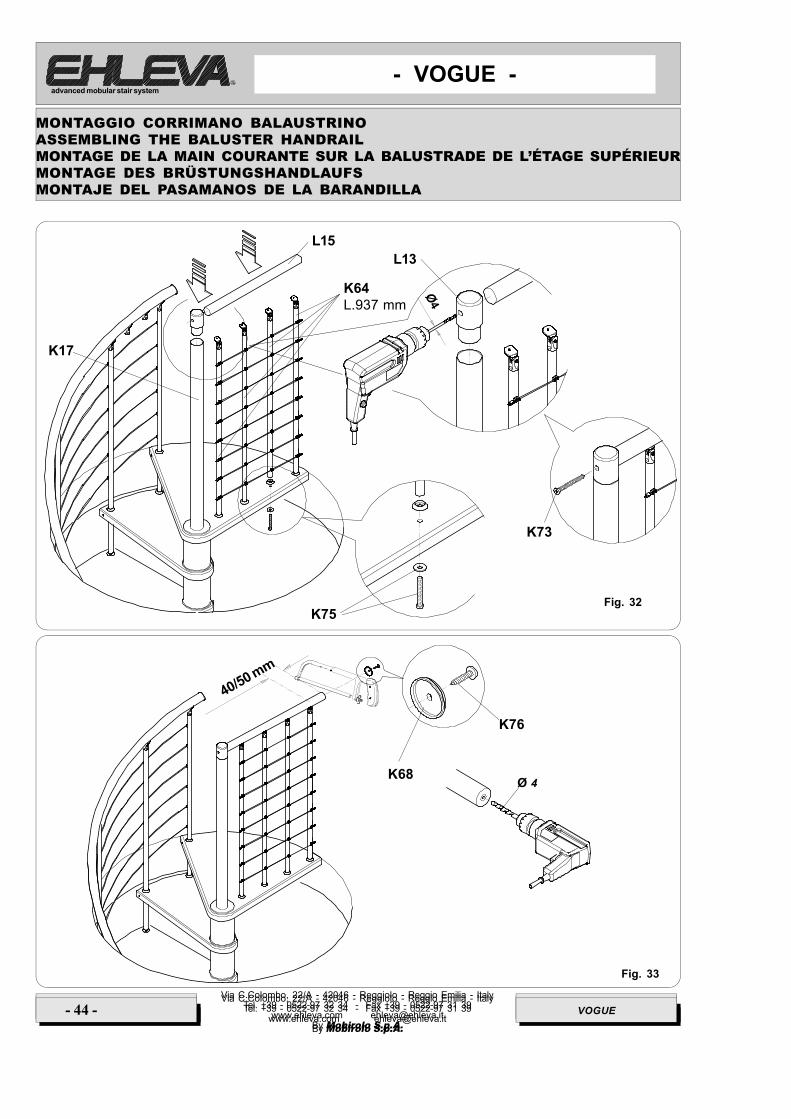
Fig. 32
Fig. 33
K68Ø 4
L13
ØK17
K73
K75
K64L.937 mm
L15
K76
Via C.Colombo, 22/A - 42046 - Reggiolo - Reggio Emilia - ItalyTel. +39 - 0522-97 32 34 - Fax +39 - 0522-97 31 39
www.ehleva.com [email protected] Mobirolo S.p.A.
- 44 - VOGUE
MONTAGGIO CORRIMANO BALAUSTRINOASSEMBLING THE BALUSTER HANDRAILMONTAGE DE LA MAIN COURANTE SUR LA BALUSTRADE DE L’ÉTAGE SUPÉRIEURMONTAGE DES BRÜSTUNGSHANDLAUFSMONTAJE DEL PASAMANOS DE LA BARANDILLA

Via C.Colombo, 22/A - 42046 - Reggiolo - Reggio Emilia - ItalyTel. +39 - 0522-97 32 34 - Fax +39 - 0522-97 31 39
www.ehleva.com [email protected] Mobirolo S.p.A.
- 45 -VOGUE
- VOGUE -advanced mobular stair system
Via C.Colombo, 22/A - 42046 - Reggiolo - Reggio Emilia - ItalyTel. +39 - 0522-97 32 34 - Fax +39 - 0522-97 31 39
www.ehleva.com [email protected] Mobirolo S.p.A.
- 23 - VOGUE
COMPLETAMENTO E VERIFICHE
A montaggio completato, verificare e controllare la stabilità della scala e che tutti i componenti siano fissati saldamente.
Posizionare la staffa K38 alla parete in modo che risulti in corrispondenza tra due gradini e ad un’altezza adeguata(circa metà scala). Come indicato in fig. 34
COMPLETION AND CHECKS
After the assembly operations have been completed, check and test that the staircase is stable and all components
are firmly anchored.Place the K38 bracket on the wall so that it is located between two steps at the correct height (approx. halfway ofthe staircase) as shown in Fig. 34
COMPLÉMENTS ET CONTRÔLES
Une fois le montage terminé, vérifier et contrôler la stabilité de l’escalier et la solidité des fixations de tous les
composants.Positionner l’étrier K38 au mur de sorte qu’il soit placé entre deux marches et à une hauteur appropriée (à peu prèsà mi-escalier). Comme indiqué fig. 34
VERVOLLSTÄNDIGUNG UND PRÜFUNGEN
Nach vollendeter Montage ist die Stabilität der Treppe zu prüfen und zu kontrollieren, dass alle Bauteile gut befestigt
sind.Das Spanneisen K38 so an der Wand positionieren, dass es sich zwischen zwei Stufen und an einer angemessenenHöhe befindet (etwa an der Treppenmitte). Abb. 34
ACABADO Y COMPROBACIONES
Una vez terminado el montaje, compruebe la estabilidad de la escalera y que todos los componentes estén bien
fijados.Fije el estribo K38 a la pared de modo que quede entre dos escalones y a una altura adecuada (aproximadamentea mitad de escalera). Como se indica en la fig. 34.
K38
K36
K38
Ø10Tassello
K38
Fig. 34