review interventional imaging – a modern telemacheia
TRANSCRIPT

365
Romanian Journal of Cardiology | Vol. 30, No. 3, 2020
REVIEW
Interventional imaging – a modern TelemacheiaCatalin Loghin, Andrei Loghin
Contact address:Catalin Loghin, MDProfessor of Cardiovascular MedicineDivision of Cardiology, McGovern Medical School at UTHealth, Room MSB 1.2466431 Fannin St. Houston, TX 770030, USAE-mail: [email protected]
McGovern Medical School at UTHealth Division of Cardiology, St. Houston, TX, USA
Abstract: Interventional imaging is maturing into a complex field, which addresses an extremely diverse pathology and integrates the findings of multimodality imaging. The interventional imager is an essential member of a multidisciplinary team focused on the transcatheter treatment of structural heart disease. Advanced echocardiography and cardiac computed tomography techniques and interpretation skills are required in order to provide instrumental information in all stages of patient care, from diagnosis through intraprocedural guidance and follow-up.Keywords: interventional imaging, structural heart disease, transcatheter valve therapies, transesophageal and transthora-cic echocardiography, cardiac computed tomography.
integrated and must be interpreted in clinical context for each patient. As such, the interventional imager is responsible for vetting the procedure as meeting essential criteria: (i) clinically indicated, (ii) applicable to a suitable anatomy, and (iii) technically feasible. This critical analysis ensures the judicious use of structural heart invasive procedures as well as favorable patient outcomes.
TTE represents the fundamental screening tool used to identify patients amenable to percutaneous interventions. It follows standard echocardiographic imaging principles, with a clear understanding of the limitations and assumptions of each technique used3,4. Excessive reliance on one criterion or another, in-stead of corroborating all existing data, typically re-sults in overestimation of lesion severity and leads to unnecessary procedures. TTE, when correctly executed and interpreted, ensures data reproduci-bility, thus allowing meaningful comparative studies, particularly useful for patients studied under variable hemodynamic conditions. A complete TTE diagno-sis must encompass: lesion etiology and mechanism, assessment of severity, comprehensive hemodynamic data i.e. mean gradients, peak velocities, quantification of effective orifice areas and regurgitant jets volumes, as well as the hemodynamic data at the time of ima-ge acquisition (i.e. heart rate for mitral stenosis mean
InTRoduCTIonThe recent exponential growth and interest in trans-catheter therapies of structural heart disease fostered the development of a new subspecialty: interventio-nal imaging. Encompassing a multimodality approach, interventional imaging had to address complex chal-lenges and, in doing so, contributed greatly to a rapid and unprecedented development of cardiac imaging in general.
The interventional imager is an essential member of the multidisciplinary “heart team”. This practical concept brings together physicians with different ex-pertise: cardiovascular surgeons, invasive cardiolo-gists, radiologists, and anesthesiologists, all dedicated to transcatheter therapies. In a genuine collaborative environment, the imager provides critical input for de-cisions made in every stage of patient care1.
The process begins with a complete anatomic and functional diagnosis of structural heart lesions2. This requires a multimodality approach which inclu-des transthoracic (TTE) and transesophageal (TEE) echocardiography, cardiac computed tomography angiography (CCTA) and, to a lesser extent, cardiac magnetic resonance imaging (CMRI). TTE represents the foundation for each case study. TEE, CCTA and CMRI complement and cannot be substituted for a comprehensive TTE study. All imaging datasets are

Catalin Loghin et al.Interventional imaging – a modern Telemacheia
Romanian Journal of CardiologyVol. 30, No. 3, 2020
366
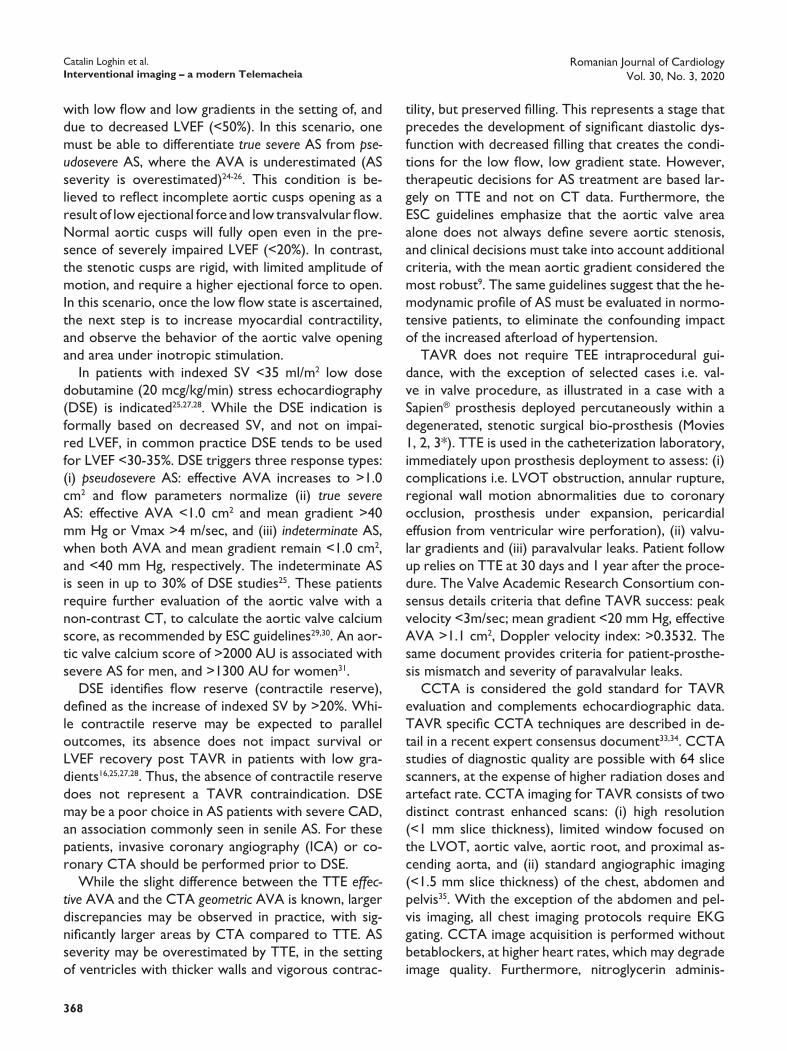
Figure 1. 3D TEE “Surgeon’s view”L = aortic left coronary cusp; A = anterior tricuspid leaflet; R = aortic right coronary cusp; S = septal tricuspid leaflet; NC = aortic noncoronary cusp; P = posterior tricuspid leaflet; RCA = right coronary artery; LAA = left atrial appendage; AVN = atrio-ventricular node; CS = coronary sinus; A1 = lateral anterior mitral scallop; P1 = medial posterior mitral scallop; A2 = mid anterior mitral scallop; P2 = mid posterior mitral scallop; A3 = medial anterior mitral scallop; P3 = medial posterior mitral scallop; IVS = interventricular septum; Aorto – Mitral curtain separates aortic and mitral valves.Note: structure identification is facilitated by remembering anatomic landmarks: (i) aorta and left ventricular outflow tract – anterior, (ii) LAA – lateral, (iii) NC – always adjacent to the interatrial septum, (iv) anterior mitral leaflet larger than posterior, with convex shape; posterior leaflet smaller, with concave shape, (iv) coronary sinus – posterior.
dized TEE views, as well as from surgical views, ideally co-registered and fused with fluoroscopic projections. A simple and practical framework is to identify the left atrial appendage (LAA) as a lateral structure, aor-tic valve and left ventricular outflow tract as anteri-or structures, pulmonary veins and coronary sinus as posterior structures, and the interventricular and in-teratrial septum as medial structures (Figure 1). Once these reference landmarks are located, any other ana-tomical structure can then be easily identified. Using this systematic approach, any non-standard TEE sec-tion can be described accurately, and the information is reliably shared between all team members.
The interventional imager must be familiar with all procedural steps and the required, often non stan-dardized TEE views. The ability to recognize in real time any potential complications is paramount. As hemodynamic conditions change rapidly, imaging data must be interpreted accordingly, in particular for re-
gradients, left ventricular ejection fraction and stroke volume for aortic stenosis, systolic blood pressure and intravascular volume status for mitral regurgitation). TEE will complement TTE by providing detailed ana-tomical data.
Intraprocedural TEE is an essential tool for most structural heart disease interventions and requires advanced technical skills and interpretation exper tise. The echocardiographer must: (i) acquire diagnostic quality images quickly, (ii) communicate relevant fin-dings to the interventional cardiologist, (iii) monitor the development of procedural complications, (iv) assess rapidly changing hemodynamic conditions, and (v) evaluate the final result based on lesion specific criteria, prior to the conclusion of the procedure.
Communication between team members repre-sents a particular challenge which relies on common definitions of anatomical landmarks and their spatial location. These landmarks are derived from standar-

Romanian Journal of CardiologyVol. 30, No. 3, 2020
367
Catalin Loghin et al.Interventional imaging – a modern Telemacheia
CCTA protocol, without performing a TEE. Overall, planimetric measurement of the TEE geometric AVA tends to be smaller by 0.1-0.2 cm2 compared to the CCTA geometric AVA, and both geometric measure-ments tend to be slightly larger compared to the TTE calculated effective AVA13-15.
In order to ensure appropriate patient selection for TAVR, the diagnostic imaging cardiologist must fully understand all distinct hemodynamic presentations of AS. True severe AS (definition based only on effecti-ve AVA <1 cm2 or <0.6 cm2/m2) can be present even if the hemodynamic criteria described above are not met, in the presence of preserved LVEF (>50%), a con-dition described as low flow, low gradient, severe AS (“paradoxical AS”)16-21. This is encountered in patients with low SV, which results in low flow rate defined as an indexed SV <35 ml/m2 of BSA and low gradient de-fined mean gradient <40 mm Hg, or Vmax <4 m/sec. It is important to differentiate the low SV that occurs as a result of low LVEF, and the low SV that may be pre-sent with normal LVEF. Expressed differently, normal LVEF does not always imply normal SV.
Normal LVEF with low SV is encountered in severe AS that associates one or more of the following con-ditions, which lead to either (i) ventricular underfilling: gross concentric hypertrophy with small ventricular cavity volume, highly increased myocardial stiffness and restrictive filling pattern by TTE; moderate or severe mitral stenosis or tricuspid regurgitation; severe intra-vascular volume depletion; atrial fibrillation with rapid ventricular response, or to (ii) abnormal ventricular emptying: moderate or severe mitral regurgitation. In such a scenario, left ventricular filling is diminished and, despite a preserved LVEF, the net result is a low SV and low flow rate which, in turn, lead to decrea-sed transvalvular gradients and velocities even if seve-re AS is present. For patients with suspected severe AS, and preserved LVEF who present with a low flow, low gradients state, an additional echocardiographic index has been proposed: pressure recovery adjusted indexed AVA. Also known as the energy loss index (ELI) it is calculated as: AVA×Aa/(Aa–AVA)/m2, where Aa is area at the sinotubular junction22. Recently, ELI has been shown helpful for the correct classification as moderate AS in nearly 40% of those cases presenting with low flow, low gradient, preserved LVEF and cal-culated effective AVA <1.0 cm2 23.
A different hemodynamic profile exists in patients with calculated effective AVA <1 cm2 or <0.6 cm2/m2),
gurgitant lesions or large paravalvular leaks (PVL). With the exception of transcatheter aortic valve re-placement (TAVR) which does not require intrapro-cedural TEE imaging guidance, virtually all other struc-tural heart disease transcatheter interventions are fundamentally imaging driven procedures.
AoRTIC VAlVETAVR is established as an effective treatment of aor-tic stenosis (AS), and a viable alternative to surgical valve replacement. From an imaging perspective, the goals of preprocedural planning are to: (i) identify the patients for whom the procedure is appropriate i.e. correct diagnosis of true severe aortic stenosis, (ii) describe specific anatomic landmarks for precise valve sizing, and (iii) determine anatomical feasibility with an acceptable risk5. A detailed description of the parame-ters required for TAVR evaluation has been previously published6.
TAVR addresses true severe AS, which is defined by ACC/AHA as peak aortic velocity (Vmax) >4 m/sec, or mean transvalvular gradient >40 mm Hg, associated with an aortic valve area (AVA) <1.0 cm2 or indexed area <0.6 cm2/m2 of body surface area (BSA)7,8. AS is considered severe if these criteria are met, irrespec-tive of the left ventricular ejection fraction (LVEF) and flow rate. AS evaluation requires very precise TTE or TEE measurements of both 2D and Doppler parame-ters. Perhaps the single most common errors encoun-tered in practice are the underestimation of the LVOT diameter, and of the left ventricular outflow tract (LVOT) time velocity integral, when the sample vo lume is placed away from the aortic valve. Both measure-ment errors lead to similar results: underestimation of the effective AVA and overestimation of AS severity. In most cases, TTE is the only required examination. TEE may complement the TTE data, in particular when 3D data sets are acquired9. TEE allows a better anato-mic definition of the anatomy of the aortic cusps, their range of motion and, arguably, a precise planimetry measurement of the geometric AVA (in contrast to the TTE Doppler calculated effective AVA). TEE also pro-vides accurate aortic annulus dimensions. Further more, TEE allows planimetry of the LVOT area, necessary in the correct calculation of stroke volume (SV). This is relevant as TTE based SV calculation assumes that the LVOT is a circular structure, a concept proven erroneous by CCTA studies which demonstrated an oval LVOT10-12. Despite its limitations, a good quality TTE study must only be complemented by a complete
Catalin Loghin et al.Interventional imaging – a modern Telemacheia
Romanian Journal of CardiologyVol. 30, No. 3, 2020
368
with low flow and low gradients in the setting of, and due to decreased LVEF (<50%). In this scenario, one must be able to differentiate true severe AS from pseudosevere AS, where the AVA is underestimated (AS severity is overestimated)24-26. This condition is be-lieved to reflect incomplete aortic cusps opening as a result of low ejectional force and low transvalvular flow. Normal aortic cusps will fully open even in the pre-sence of severely impaired LVEF (<20%). In contrast, the stenotic cusps are rigid, with limited amplitude of motion, and require a higher ejectional force to open. In this scenario, once the low flow state is ascertained, the next step is to increase myocardial contractility, and observe the behavior of the aortic valve opening and area under inotropic stimulation.
In patients with indexed SV <35 ml/m2 low dose dobutamine (20 mcg/kg/min) stress echocardiography (DSE) is indicated25,27,28. While the DSE indication is formally based on decreased SV, and not on impai-red LVEF, in common practice DSE tends to be used for LVEF <30-35%. DSE triggers three response types: (i) pseudosevere AS: effective AVA increases to >1.0 cm2 and flow parameters normalize (ii) true severe AS: effective AVA <1.0 cm2 and mean gradient >40 mm Hg or Vmax >4 m/sec, and (iii) indeterminate AS, when both AVA and mean gradient remain <1.0 cm2, and <40 mm Hg, respectively. The indeterminate AS is seen in up to 30% of DSE studies25. These patients require further evaluation of the aortic valve with a non-contrast CT, to calculate the aortic valve calcium score, as recommended by ESC guidelines29,30. An aor-tic valve calcium score of >2000 AU is associated with severe AS for men, and >1300 AU for women31.
DSE identifies flow reserve (contractile reserve), defined as the increase of indexed SV by >20%. Whi-le contractile reserve may be expected to parallel outcomes, its absence does not impact survival or LVEF recovery post TAVR in patients with low gra-dients16,25,27,28. Thus, the absence of contractile re serve does not represent a TAVR contraindication. DSE may be a poor choice in AS patients with severe CAD, an association commonly seen in senile AS. For these patients, invasive coronary angiography (ICA) or co-ronary CTA should be performed prior to DSE.
While the slight difference between the TTE effective AVA and the CTA geometric AVA is known, larger discrepancies may be observed in practice, with sig-nificantly larger areas by CTA compared to TTE. AS severity may be overestimated by TTE, in the setting of ventricles with thicker walls and vigorous contrac-
tility, but preserved filling. This represents a stage that precedes the development of significant diastolic dys-function with decreased filling that creates the condi-tions for the low flow, low gradient state. However, therapeutic decisions for AS treatment are based lar-gely on TTE and not on CT data. Furthermore, the ESC guidelines emphasize that the aortic valve area alone does not always define severe aortic stenosis, and clinical decisions must take into account additional criteria, with the mean aortic gradient considered the most robust9. The same guidelines suggest that the he-modynamic profile of AS must be evaluated in normo-tensive patients, to eliminate the confounding impact of the increased afterload of hypertension.
TAVR does not require TEE intraprocedural gui-dance, with the exception of selected cases i.e. val-ve in valve procedure, as illustrated in a case with a Sapien® prosthesis deployed percutaneously within a degenerated, stenotic surgical bio-prosthesis (Movies 1, 2, 3*). TTE is used in the catheterization laboratory, immediately upon prosthesis deployment to assess: (i) complications i.e. LVOT obstruction, annular rupture, regional wall motion abnormalities due to coronary occlusion, prosthesis under expansion, pericardial effusion from ventricular wire perforation), (ii) valvu-lar gradients and (iii) paravalvular leaks. Patient follow up relies on TTE at 30 days and 1 year after the proce-dure. The Valve Academic Research Consortium con-sensus details criteria that define TAVR success: peak velocity <3m/sec; mean gradient <20 mm Hg, effective AVA >1.1 cm2, Doppler velocity index: >0.3532. The same document provides criteria for patient-prosthe-sis mismatch and severity of paravalvular leaks.
CCTA is considered the gold standard for TAVR evaluation and complements echocardiographic data. TAVR specific CCTA techniques are described in de-tail in a recent expert consensus document33,34. CCTA studies of diagnostic quality are possible with 64 slice scanners, at the expense of higher radiation doses and artefact rate. CCTA imaging for TAVR consists of two distinct contrast enhanced scans: (i) high resolution (<1 mm slice thickness), limited window focused on the LVOT, aortic valve, aortic root, and proximal as-cending aorta, and (ii) standard angiographic imaging (<1.5 mm slice thickness) of the chest, abdomen and pelvis35. With the exception of the abdomen and pel-vis imaging, all chest imaging protocols require EKG gating. CCTA image acquisition is performed without betablockers, at higher heart rates, which may de grade image quality. Furthermore, nitroglycerin adminis-
Romanian Journal of CardiologyVol. 30, No. 3, 2020
369
Catalin Loghin et al.Interventional imaging – a modern Telemacheia
rements are referenced to the known dimensions of the transcatheter prostheses, provided by their ma-nufacturers. The choice of prosthesis size is based on a calculated “oversizing” percentage: (prosthesis no-minal measurement/annular measurement - 1) x 100, using either area or perimeter as reference.
The second CCTA scan is non-ECG gated and is performed to evaluate vascular access. This requires a detailed analysis of the iliofemoral arteries i.e. size, cal-cification, tortuosity, as well as characteristics of the aorta, including kinking, extensive calcification (“por-celain aorta”), aneurysms, intramural hematomas, dissections and large, complex atheroma. Incidental CCTA non-vascular findings must be reported, even though they are rarely clinically significant38. Large sen-sor (16 cm z axis) CT scanners are capable of perfor-ming the whole TAVR imaging protocol in one pass, with single contrast injection and single breath hold, which results in a 30-40% reduction of the radiation and contrast agent doses.
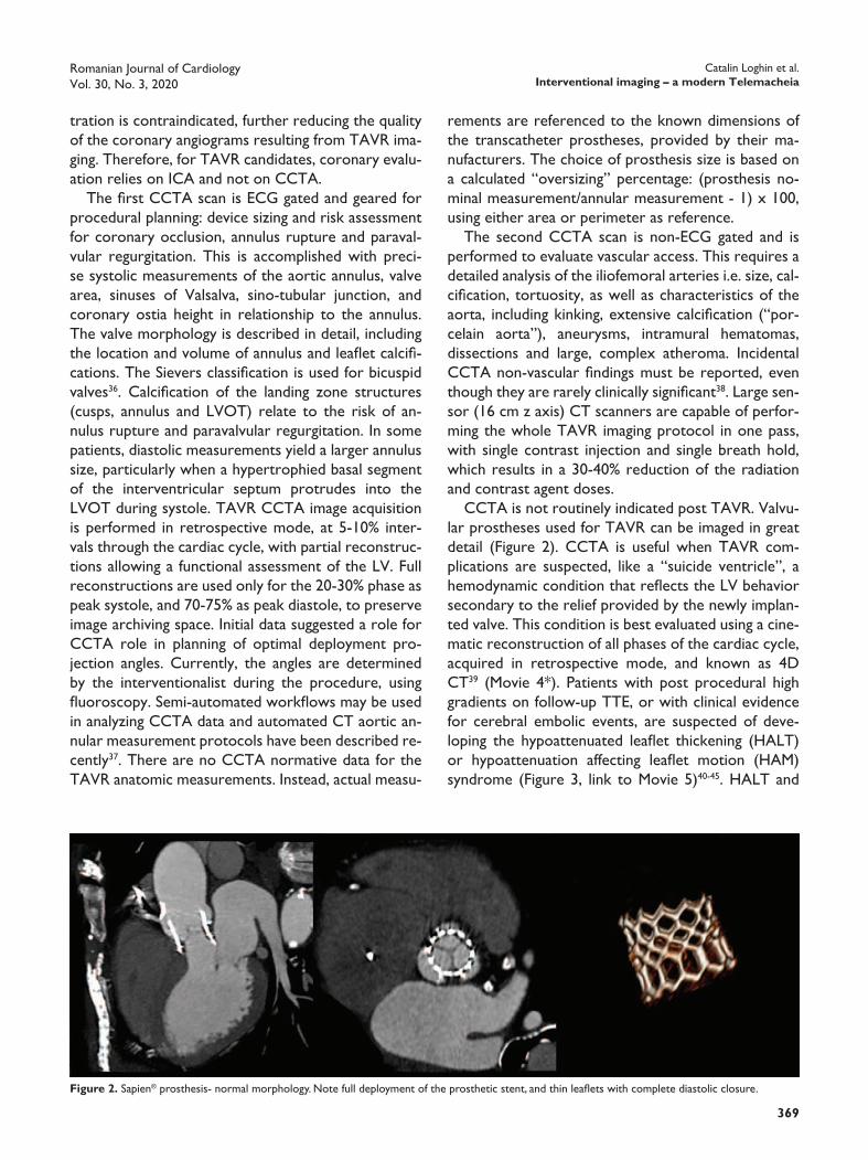
CCTA is not routinely indicated post TAVR. Valvu-lar prostheses used for TAVR can be imaged in great detail (Figure 2). CCTA is useful when TAVR com-plications are suspected, like a “suicide ventricle”, a hemodynamic condition that reflects the LV behavior secondary to the relief provided by the newly implan-ted valve. This condition is best evaluated using a cine-matic reconstruction of all phases of the cardiac cycle, acquired in retrospective mode, and known as 4D CT39 (Movie 4*). Patients with post procedural high gradients on follow-up TTE, or with clinical evidence for cerebral embolic events, are suspected of deve-loping the hypoattenuated leaflet thickening (HALT) or hypoattenuation affecting leaflet motion (HAM) syndrome (Figure 3, link to Movie 5)40-45. HALT and
tration is contraindicated, further reducing the quality of the coronary angiograms resulting from TAVR ima-ging. Therefore, for TAVR candidates, coronary evalu-ation relies on ICA and not on CCTA.
The first CCTA scan is ECG gated and geared for procedural planning: device sizing and risk assessment for coronary occlusion, annulus rupture and paraval-vular regurgitation. This is accomplished with preci-se systolic measurements of the aortic annulus, valve area, sinuses of Valsalva, sino-tubular junction, and coronary ostia height in relationship to the annulus. The valve morphology is described in detail, including the location and volume of annulus and leaflet calcifi-cations. The Sievers classification is used for bicuspid valves36. Calcification of the landing zone structures (cusps, annulus and LVOT) relate to the risk of an-nulus rupture and paravalvular regurgitation. In some patients, diastolic measurements yield a larger annulus size, particularly when a hypertrophied basal segment of the interventricular septum protrudes into the LVOT during systole. TAVR CCTA image acquisition is performed in retrospective mode, at 5-10% inter-vals through the cardiac cycle, with partial reconstruc-tions allowing a functional assessment of the LV. Full reconstructions are used only for the 20-30% phase as peak systole, and 70-75% as peak diastole, to preserve image archiving space. Initial data suggested a role for CCTA role in planning of optimal deployment pro-jection angles. Currently, the angles are determined by the interventionalist during the procedure, using fluoroscopy. Semi-automated workflows may be used in analyzing CCTA data and automated CT aortic an-nular measurement protocols have been described re-cently37. There are no CCTA normative data for the TAVR anatomic measurements. Instead, actual measu-
Figure 2. Sapien® prosthesis- normal morphology. Note full deployment of the prosthetic stent, and thin leaflets with complete diastolic closure.

Catalin Loghin et al.Interventional imaging – a modern Telemacheia
Romanian Journal of CardiologyVol. 30, No. 3, 2020
370
phenomenon, where pressure increases post-stenosis due to conversion of kinetic to potential energy. In such cases, CCTA can directly visualize the degree of prosthesis expansion, leaflet thickness or mobility, as well as the aorta size, thereby identifying the mecha-nism of increased transvalvular gradients post TAVR.
MITRAl VAlVEMitral regurgitation (MR) is the second most frequent valve disease in Europe. Most commonly, it is non-rheumatic in etiology, and carries a high mortality rate, proportional to its severity30.
A simplified etiology classification identifies primary (degenerative) regurgitation (DMR) as a condition directly affecting the mitral apparatus, and secon-dary (functional) regurgitation (FMR) as a condition affecting the myocardium and, indirectly, the closing
HAM are associated with leaflet thrombosis, and their evaluation implies the use of both CT 2D views and 4D CT reconstructions (Figure 4). 4D CT is particu-larly useful for the evaluation of degenerated surgical or transcatheter bioprostheses, when a valve in valve procedure is contemplated. In these patients, CCTA imaging complements and may be superior to 3D TEE for anatomic detail, as it may overcome the shadowing artefacts seen in the presence of highly echogenic ma-terial.
Post TAVR, large discrepancies between catheter derived and TTE gradients may be observed occa-sionally46,47. The higher TTE gradients may be due to the underexpansion of the prosthesis, in particular for self-expandable models. This leads to a degree of re-sidual stenosis and, in particular for an aortic diame-ter <30 mm, the occurrence of the pressure recovery
Figure 4. CCTA: Perceval® valve with HAM (hypoattenuation affecting leaflet motion) and leaflet thrombosis. Note thickening and incomplete diastolic closure, with thrombosis affecting two leaflets; 3D reconstruction demonstrates normal stent morphology.
Figure 3. HALT (hypoattenuation leaflet thickening); 2D TEE Sapien® prosthesis. Note thickened leaflets, with incomplete diastolic closure.
Romanian Journal of CardiologyVol. 30, No. 3, 2020
371
Catalin Loghin et al.Interventional imaging – a modern Telemacheia
therapy, and resynchronization therapy, and coronary revascularization as needed59. Expressed differently, the MitraClip® procedure is reserved only for patients with severe enough MR, left ventricular size and systo-lic performance which are not too severely altered, who exhausted alternative therapies (resynchroniza-tion and revascularization), cannot tolerate surgery, and have persistent symptoms despite maximum me-dical therapy.
While current data supports the role of three-di-mensional evaluation (3D) to calculate EROA and RV, no single echocardiographic technique or parameter can fully describe MR. An experienced imager will cognitively integrate multiple criteria to formulate an accurate and complete diagnosis. Occasionally, CMRI is used for its ability to measure very accurately the regurgitant area, volume and fraction. Similarly, supine bicycle TTE may be useful to reveal the true MR seve-rity in patients with symptoms out of proportion with the TTE data, by observing stress induced increase of MR severity and of the systolic pulmonary pressure, which may be underestimated in resting state. Quan-tification of the effective mitral orifice area (EMOA) is relatively accurate in echocardiography, and pati-ents with EMOA <4.0 cm2 are not considered ideal candidates given the risk of iatrogenic mitral stenosis. However, EMOA alone cannot predict the transmitral gradients resulting from edge-to-edge repair.
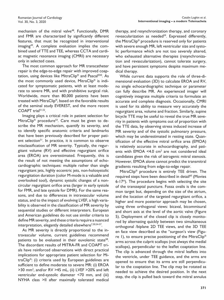
MitraClip® procedure is entirely TEE driven. The required steps have been described in detail60 (Movies 6-17*). The procedure begins with selecting the site of the transseptal puncture. Fossa ovalis is the com-mon target but, depending on the size of the atrium, and the location of the targeted regurgitant orifice, a higher and more posterior approach may be chosen, using three orthogonal views: bicaval, bicommisural and short axis at the level of the aortic valve (Figure 5). Deployment of the closed clip is closely monito-red by alternating quickly between two simultaneous orthogonal /biplane 2D TEE views, and the 3D TEE en face view described as the “surgeon’s view (Figu-re 1), to ensure precise positioning of the MitraClip® arms across the culprit scallops (not always the medial scallops), perpendicular to the leaflet coaptation line. The clip is advanced through the mitral leaflets into the ventricle, under TEE guidance, and the arms are opened to ensure that its arms are still perpendicu-lar to the coaptation line. The clip may be rotated as needed to achieve the desired position. In the next step, the clip is pulled back toward the mitral annulus
mechanism of the mitral valve48. Functionally, DMR and FMR are characterized by significantly different features, that must be recognized in interventional imaging49. A complete evaluation implies the com-bined used of TTE and TEE, whereas CCTA and cardi-ac magnetic resonance imaging (CMRI) are necessary only in selected cases.
The most common approach for MR transcatheter repair is the edge-to-edge repair with improved coap-tation, using devices like MitraClip® and Pascal®50. As the most commonly used device, MitraClip® is indi-cated for symptomatic patients, with at least mode-rate to severe MR, and with prohibitive surgical risk. Worldwide, more than 80,000 patients have been treated with MitraClip®, based on the favorable results of the seminal study EVEREST, and the more recent COAPT trial51,52.
Imaging plays a critical role in patient selection for MitraClip® procedure53. Care must be given to de-scribe the MR mechanism, quantify its severity, and to identify specific anatomic criteria and landmarks that have been previously described for proper pati-ent selection51. In practice, it is common to observe misclassification of MR severity. Typically, the regur-gitant volume (RV) and effective regurgitant orifice area (EROA) are overestimated. Frequently, this is the result of not meeting the assumptions of echo-cardiographic techniques: multiple rather than single regurgitant jets, highly eccentric jets, non-holosystolic regurgitation duration (color M-mode is a valuable and overlooked tool), dynamic systolic changes of a non-circular regurgitant orifice area (larger in early systole for FMR, and late systole for DMR). For the same rea-sons, and due to differences in intravascular volume status, and to the impact of evolving LVEF, a high varia-bility is observed in the classification of MR severity by sequential studies or different interpreters. European and American guidelines do not use similar criteria to define MR severity, and these criteria require a nu anced interpretation, elegantly detailed else where7,30,54-57.
As MR severity is directly proportional to the in-travascular volume, current guidelines recommend patients to be evaluated in their euvolemic state58. The discordant results of MITRA-FR and COAPT tri-als have reinforced observations with direct practical implications for appropriate patient selection for Mi-traClip®: (i) criteria used by European guidelines are sufficient to define moderate to severe MR: (i) EROA >30 mm2, and/or RV >45 mL, (ii) LVEF >20% and left ventricular end-systolic diameter <70 mm, and (iii) NYHA class >II after maximally tolerated medical

Catalin Loghin et al.Interventional imaging – a modern Telemacheia
Romanian Journal of CardiologyVol. 30, No. 3, 2020
372
following atrial remodeling and possible recovery of atrial contractility, in particular during exercise, and are measured at 30 days or later by surveillance TTE studies62. In addition to mitral stenosis, post procedu-ral iatrogenic atrial septal defects are identified by 2D and 3D TEE in up to 24% of MitraClip® cases, with a 26% rehospitalization rate (Figure 7)63,64. Of those with an iatrogenic atrial septal defect, only 5% will develop a right to left shunt, and most patients do not require defect closure65.
As a result of the complexity of imaging evaluation and the difficulty in manipulating and deploying the de-vice in a very precise location, the MitraClip® proce-dure is exceptionally challenging, with a steep learning curve, and requires a perfectly coordinated effort of the entire team.
so that the valve leaflets are fully captured between the device arms and their grippers, as monitored with a biplane 2D TEE LVOT and bicommisural view. The deployment of a first clip commonly results in signifi-cant reduction of the regurgitation severity. Howe-ver, the tension the clip arms apply to the leaflets and subvalvular apparatus may lead to significant anatomi-cal changes, with the development of new regurgitant orifices, of variable shape and location, requiring a ra-pid and complete reevaluation of the new target are-as for the deployment of additional clips (Movie 18*). The goal is to obtain less than moderate MR, ideally mild, with mean transmitral gradient <5 mm Hg, at a heart rate of 70-80 bpm, and a systolic blood pressure of 120-140 mm Hg.
The MitraClip® procedure evolved from a single clip implantation to the deployment of two or more devi-ces, aiming to improve coaptation for more than the medial mitral scallops. Typically, additional clips are not deployed if mean gradients ≥5 mm Hg are ob-served, to avoid iatrogenic mitral stenosis61 (Figure 6). Therefore, it is imperative to monitor transmitral gra-dients immediately after deployment of each clip, with deliberate manipulation of the afterload and heart rate. At the same time, the severity of the residual regurgitation is quantified, using criteria described by the mitral valve consortium. While mitral gradients are primarily a function of the heart rate, they are also driven by preload and the ejection fraction of the left atrium. Mitral gradients change post procedure,
Figure 7. TEE bicaval view: iatrogenic, left to right atrial septal defect.
Figure 6. Intraoperative TEE MitraClip® procedure: post deployment transmitral gradients. Note: a mean mitral gradient of 5 mm Hg precludes the implantation of an additional clip.
Figure 5. TEE biplane view: MitraClip® procedure guided transseptal crossing. TEE near orthogonal biplane views (modified bicaval and short axis aortic valve) identifies the location of the transseptal needle in the fos-sa ovalis, and posterior to the aorta, prior to crossing. The crossing height relative to the mitral annulus is measured, to ensure device maneuverability.
Romanian Journal of CardiologyVol. 30, No. 3, 2020
373
Catalin Loghin et al.Interventional imaging – a modern Telemacheia
delivery axis perpendicular to the mitral annulus. Due to their large profile, TMVR prostheses tend to pro-trude in the LVOT, thus creating a “neo-LVOT”. This may result in LVOT dynamic obstruction, a serious TMVR specific complication66-68.
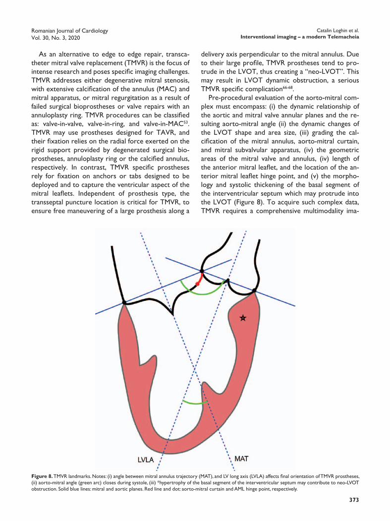
Pre-procedural evaluation of the aorto-mitral com-plex must encompass: (i) the dynamic relationship of the aortic and mitral valve annular planes and the re-sulting aorto-mitral angle (ii) the dynamic changes of the LVOT shape and area size, (iii) grading the cal-cification of the mitral annulus, aorto-mitral curtain, and mitral subvalvular apparatus, (iv) the geometric areas of the mitral valve and annulus, (iv) length of the anterior mitral leaflet, and the location of the an-terior mitral leaflet hinge point, and (v) the morpho-logy and systolic thickening of the basal segment of the interventricular septum which may protrude into the LVOT (Figure 8). To acquire such complex data, TMVR requires a comprehensive multimodality ima-
As an alternative to edge to edge repair, transca-theter mitral valve replacement (TMVR) is the focus of intense research and poses specific imaging challenges. TMVR addresses either degenerative mitral stenosis, with extensive calcification of the annulus (MAC) and mitral apparatus, or mitral regurgitation as a result of failed surgical bioprostheses or valve repairs with an annuloplasty ring. TMVR procedures can be classified as: valve-in-valve, valve-in-ring, and valve-in-MAC53. TMVR may use prostheses designed for TAVR, and their fixation relies on the radial force exerted on the rigid support provided by degenerated surgical bio-prostheses, annuloplasty ring or the calcified annulus, respectively. In contrast, TMVR specific prostheses rely for fixation on anchors or tabs designed to be deployed and to capture the ventricular aspect of the mitral leaflets. Independent of prosthesis type, the transseptal puncture location is critical for TMVR, to ensure free maneuvering of a large prosthesis along a
Figure 8. TMVR landmarks. Notes: (i) angle between mitral annulus trajectory (MAT), and LV long axis (LVLA) affects final orientation of TMVR prostheses, (ii) aorto-mitral angle (green arc) closes during systole, (iii) *hypertrophy of the basal segment of the interventricular septum may contribute to neo-LVOT obstruction. Solid blue lines: mitral and aortic planes. Red line and dot: aorto-mitral curtain and AML hinge point, respectively.
Catalin Loghin et al.Interventional imaging – a modern Telemacheia
Romanian Journal of CardiologyVol. 30, No. 3, 2020
374
complemented by TEE or CCTA only if prosthesis malfunction is suspected.
lEFT ATRIAl AppEndAgE ExClusIonSeveral transcatheter delivered devices have been em-ployed for the mechanical exclusion of the left atrial appendage (LAA), in patients who are not good can-didates for chronic oral anticoagulation73. The Watch-man® device has accumulated the largest experience, with over 100,000 patients treated.
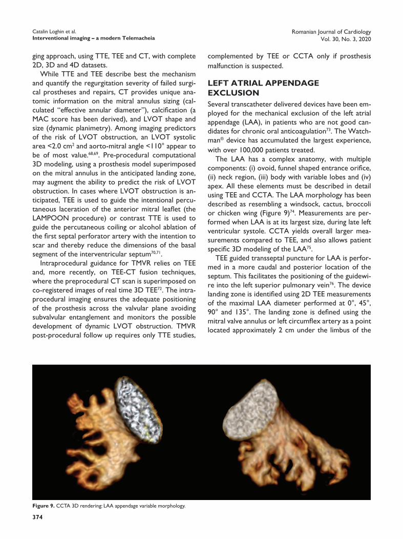
The LAA has a complex anatomy, with multiple components: (i) ovoid, funnel shaped entrance orifice, (ii) neck region, (iii) body with variable lobes and (iv) apex. All these elements must be described in detail using TEE and CCTA. The LAA morphology has been described as resembling a windsock, cactus, broccoli or chicken wing (Figure 9)74. Measurements are per-formed when LAA is at its largest size, during late left ventricular systole. CCTA yields overall larger mea-surements compared to TEE, and also allows patient specific 3D modeling of the LAA75.
TEE guided transseptal puncture for LAA is perfor-med in a more caudal and posterior location of the septum. This facilitates the positioning of the guidewi-re into the left superior pulmonary vein76. The device landing zone is identified using 2D TEE measurements of the maximal LAA diameter performed at 0°, 45°, 90° and 135°. The landing zone is defined using the mitral valve annulus or left circumflex artery as a point located approximately 2 cm under the limbus of the
ging approach, using TTE, TEE and CT, with complete 2D, 3D and 4D datasets.
While TTE and TEE describe best the mechanism and quantify the regurgitation severity of failed surgi-cal prostheses and repairs, CT provides unique ana-tomic information on the mitral annulus sizing (cal-culated “effective annular diameter”), calcification (a MAC score has been derived), and LVOT shape and size (dynamic planimetry). Among imaging predictors of the risk of LVOT obstruction, an LVOT systolic area <2.0 cm2 and aorto-mitral angle <110° appear to be of most value.68,69. Pre-procedural computational 3D modeling, using a prosthesis model superimposed on the mitral annulus in the anticipated landing zone, may augment the ability to predict the risk of LVOT obstruction. In cases where LVOT obstruction is an-ticipated, TEE is used to guide the intentional percu-taneous laceration of the anterior mitral leaflet (the LAMPOON procedure) or contrast TTE is used to guide the percutaneous coiling or alcohol ablation of the first septal perforator artery with the intention to scar and thereby reduce the dimensions of the basal segment of the interventricular septum70,71.
Intraprocedural guidance for TMVR relies on TEE and, more recently, on TEE-CT fusion techniques, where the preprocedural CT scan is superimposed on co-registered images of real time 3D TEE72. The intra-procedural imaging ensures the adequate positioning of the prosthesis across the valvular plane avoiding subvalvular entanglement and monitors the possible development of dynamic LVOT obstruction. TMVR post-procedural follow up requires only TTE studies,
Figure 9. CCTA 3D rendering: LAA appendage variable morphology.

Romanian Journal of CardiologyVol. 30, No. 3, 2020
375
Catalin Loghin et al.Interventional imaging – a modern Telemacheia
Post LAA occlusion, a TEE is performed at 45 days, to ensure device stability and to rule out devi-ce thrombosis, PDL, or a persistent atrial septal de-fect from the transseptal puncture. More recent data suggests that post procedural surveillance CCTA is more sensitive compared to TEE for the detection of residual PDL. This finding is attributable to the ease of obtaining orthogonal views and device 3D reconstruc-tion in CCTA, compared to the difficulty of acquiring all required LAA views by TEE (Figure 11) 81.
left upper pulmonary vein. It is important to note that the landing zone is not similar to the LAA entrance orifice, but rather distal to it, which explains the oc-casional formation of a LAA stump after the device deployment. Next, the LAA depth is defined as the distance between the landing zone plane to the LAA apex. Sizing of the Watchman® device is based on the largest measured LAA diameter, with a maximum di-ameter oversizing of <20%. Prior to device release, a “tug test” is performed, to ensure device stability in its final position (Movie 19*). After deployment, the interventional imager ensures that the device does not protrude into the LAA and is in a stable position, with adequate compression (by comparing the deployed device diameter against the undeployed measured size), and without a significant peridevice leak (PDL) (<5 mm vena contracta in color Doppler, at a Nyquist limit of 20-30 cm/s) (Figure 10, Movie 20*). Monito-ring for a pericardial effusion secondary to cardiac perforation is a particularly important responsibility of the imager, given its higher risk compared to other percutaneous procedures.
The Amulet® device deployment follows similar principles to the Watchman® procedure however, the definitions of the landing zone, LAA depth, sealing of the LAA orifice and PDL are different77-79. The LA-RIAT® device is another alternative to Watchman®, and uses combined endocardial and epicardial wires to deliver a suture which ligates the LAA, resulting in a typical “bowtie” appearance of the LAA on 3D TEE imaging80.
Figure 10. 3D TEE: Watchman® with large peridevice leak.
Figure 11. CCTA: orthogonal views reveal minimal peridevice leak in a well seated Watchman®.

Catalin Loghin et al.Interventional imaging – a modern Telemacheia
Romanian Journal of CardiologyVol. 30, No. 3, 2020
376
gated, in retrospective mode, and covers the cardiac cycle at 5-10% intervals. In contrast to TAVR, the use of betablockers is encouraged, with optimum imaging at heart rates of 55-60 bpm, to decrease artifacts re-sulting from annular motion. In some centers, CCTA is used, similar to TAVR planning, to determine the optimal fluoroscopic angles for device deployment90. CCTA may differentiate between thrombus and pan-nus, that result in incomplete leaflet closure that mi-mics PVL with TEE imaging91,92. Furthermore, similar to TMVR, CCTA is useful in predicting the risk of LVOT obstruction or anterior mitral leaflet impinge-ment, observed in particular for posteriorly located aortic PVLs.
During the procedure, TEE is essential to guide in real time defect crossing with the guidewire, in con-junction with fluoroscopic views85,90,93. This is followed by an evaluation of the correct and full deployment of the closure device, on both atrial and ventricular sides. Leaflet motion may be impaired from impingement by the adjacent closing device and, following device deployment, it is important to ascertain in real time the correct prosthesis leaflet motion, before the final release of the device. Wire traction imparts tension on surrounding tissue and may affect valve geometry. Therefore, immediately upon the final release of the device, the valve and its annulus must be reassessed carefully, and any residual or newly formed PVLs are addressed as needed. Device embolization or incom-plete deployment occur rarely and are readily evalua-ted with real time 3D TEE.
TRICuspId VAlVEDue to its particular anatomy, with many adjacent cri-tical structures (right coronary artery, coronary sinus, atrioventricular node and His bundle) that can be da-maged during a percutaneous procedure, the regurgi-tant tricuspid valve represents the single most challen-ging target for transcatheter interventions. Tricuspid regurgitation (TR) is associated with a high mortality and evolves independent of a successful repair of left sided lesions. Several techniques for percutaneous repair have been described94,95. Worldwide, there is a relatively limited experience with less than 400 pa-tients treated as reported by the TriValve registry, with the MitraClip® as the most commonly used de-vice95-100. Anatomically, tricuspid valve can be imaged by TTE and TEE, following methods amply illustrated in current guidelines and dedicated reviews101-103. For 3D TEE, the atrial view of the tricuspid valve is frequently
pARAVAlVulAR lEAKsParavalvular leaks (PVL) and regurgitation are encoun-tered in up to 18% of combined surgical and trans-catheter valve interventions82. Most PVL’s are subcli-nical, but approximately 5% may manifest with heart failure or severe hemolysis symptoms, resulting from an often eccentric, very high velocity regurgitant jet83. From an imaging perspective, PVL represents a parti-cular difficult and rewarding challenge, as it requires integration of TEE, CCTA and fluoroscopic 2D and 3D datasets (Figure 12).
TEE is the main imaging technique used for PVL repair, and requires non-conventional views and pro-cedural times which frequently exceed those needed for MitraClip®84-89. A systematic scan of the entire cir-cumference of the prosthesis is required, with particu-lar attention to the dynamic nature of the regurgitant orifice, which may remain open only through a porti-on of the cardiac cycle. 3D TEE is particularly suited for this task and relies on the “surgical view” for the mitral, and the LVOT view for the aortic prostheses. The defect is described in size (area and percent of annular circumference), location, shape, trajectory, and relationship with adjacent structures. Some PVL jets travel through serpiginous paths which may be difficult to characterize accurately in 2D reconstruc-tions. A detailed, accurate anatomic description is cri-tical for the sizing and type of the closing device.
CCTA complements the TEE data, and is parti-cularly useful for aortic PVLs, where TEE imaging is frequently suboptimal. Image acquisition must be ECG
Figure 12. Multimodality imaging: perivalvular leak (PVL)Panel A: 3D TEE “en face” view: mitral annuloplasty ring, antero-medial PVL.Panel B: 3D TEE color: late systolic regurgitant jet.Panel C: 2D TEE color, bicommisural view: valvular and PVL regurgitation.Panel D: CCTA: annuloplasty ring normal morphology, precise measure-ments of PVL dimensions.
Romanian Journal of CardiologyVol. 30, No. 3, 2020
377
Catalin Loghin et al.Interventional imaging – a modern Telemacheia
manipulation110. The reimbursement for the imaging portion of structural heart interventions is dispro-portionately low relative to the extensive time and considerable skill required by these procedures. In an environment where physicians are judged by produc-tivity rather than quality outcomes, the interventional imager is at a major disadvantage compared to his or her peers111. More importantly, the radiation exposu-re can be up to 4 times higher compared to the inter-ventional operator, with unknown long term health consequences112. In contrast, the interventional imager is rewarded by being positioned at the leading edge of cardiac imaging technical development.
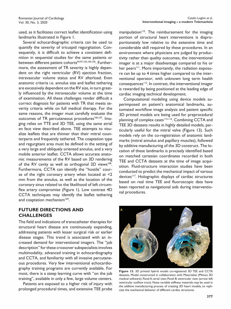
Computational modeling using device models su-perimposed on patient’s anatomical landmarks, au-tomated workflow image analysis and patient specific 3D printed models are being used for preprocedural planning of complex cases113-116. Combining CCTA and TEE 3D datasets results in highly detailed models, par-ticularly useful for the mitral valve (Figure 13). Such models rely on the co-registration of anatomic land-marks (mitral annulus and papillary muscles), followed by additive manufacturing of the 3D construct. The lo-cation of these landmarks is precisely identified based on matched cartesian coordinates recorded in both TEE and CCTA datasets at the time of image acqui-sition. Fluid-structure interaction studies have been conducted to predict the mechanical impact of various devices117. Holographic displays of cardiac structures based on real time TEE and fluoroscopic data have been reported as navigational aids during interventio-nal procedures.
used, as it facilitates correct leaflet identification using landmarks illustrated in Figure 1.
Several echocardiographic criteria can be used to quantify the severity of tricuspid regurgitation. Con-sequently, it is difficult to achieve a consistent defi-nition in sequential studies for the same patients or between different patient cohorts94,97,102,104,105. Further-more, the assessment of TR severity is highly depen-dent on the right ventricular (RV) ejection fraction, intravascular volume status and RV afterload. Even anatomic criteria i.e. annulus size and leaflet tethering are excessively dependent on the RV size, in turn great-ly influenced by the intravascular volume at the time of examination. All these challenges render difficult a correct diagnosis for patients with TR that meets se-verity criteria while on full medical therapy. For the same reasons, the imager must carefully evaluate the outcomes of TR percutaneous procedures106,107. Ima-ging relies on TTE and 3D TEE, using the same atrial en face view described above. TEE attempts to visu-alize leaflets that are thinner than their mitral coun-terparts and frequently tethered. The coaptation type and regurgitant area must be defined in the setting of a very large and obliquely oriented annulus, and a very mobile anterior leaflet. CCTA allows accurate anato-mic measurements of the RV based on 3D rendering of the RV cavity as well as orthogonal 2D views108. Furthermore, CCTA can identify the “hostile” cour-se of the right coronary artery when located at <2 mm from the annulus, as well as the location of the coronary sinus related to the likelihood of left circum-flex artery compromise (Figure 1). Low contrast 4D CCTA techniques may identify the leaflet tethering and coaptation mechanism109.
FuTuRE dIRECTIons And ChAllEngEsThe field and indications of transcatheter therapies for structural heart disease are continuously expanding, addressing patients with lesser surgical risk or earlier disease stages. This trend is associated with an in-creased demand for interventional imagers. The “job description” for these crossover subspecialists involves multimodality, advanced training in echocardiography and CCTA, and familiarity with all invasive percutane-ous procedures. Very few interventional echocardio-graphy training programs are currently available. For most, there is a steep learning curve with “on the job training”, available in only a few, large volume centers.
Patients are exposed to a higher risk of injury with prolonged procedural times, and extensive TEE probe
Figure 13. 3D printed hybrid model: co-registered 3D TEE and CCTA datasets. Model constructed in collaboration with Materialise (Mimics 3D medical software). Panel A: atrial view; Panel B: ventricular view (arrow: left ventricular outflow tract). Note: variable stiffness materials may be used in the additive manufacturing process of creating 3D heart models, to repli-cate the mechanical behavior of different cardiac structures.

Catalin Loghin et al.Interventional imaging – a modern Telemacheia
Romanian Journal of CardiologyVol. 30, No. 3, 2020
378
placement: Role of Multimodality Imaging in Common and Complex Clinical Scenarios. JACC Cardiovasc Imaging. 2020;13:124-139.
6. Otto CM, Kumbhani DJ, Alexander KP, Calhoon JH, Desai MY, Kaul S, Lee JC, Ruiz CE and Vassileva CM. 2017 ACC Expert Consensus Decision Pathway for Transcatheter Aortic Valve Replacement in the Management of Adults With Aortic Stenosis: A Report of the American College of Cardiology Task Force on Clinical Expert Con-sensus Documents. J Am Coll Cardiol. 2017;69:1313-1346.
7. Nishimura RA, Otto CM, Bonow RO, Carabello BA, Erwin JP, 3rd, Fleisher LA, Jneid H, Mack MJ, McLeod CJ, O’Gara PT, Rigolin VH, Sundt TM, 3rd and Thompson A. 2017 AHA/ACC Focused Update of the 2014 AHA/ACC Guideline for the Management of Patients With Valvular Heart Disease: A Report of the American College of Cardiology/American Heart Association Task Force on Clinical Practice Guidelines. J Am Coll Cardiol. 2017;70:252-289.
8. Aortic Stenosis Writing G, Bonow RO, Brown AS, Gillam LD, Ka-padia SR, Kavinsky CJ, Lindman BR, Mack MJ, Thourani VH, Aortic Stenosis Rating P and Appropriate Use Criteria Task F. ACC/AATS/AHA/ASE/EACTS/HVS/SCA/SCAI/SCCT/SCMR/STS 2017 Appro-priate use criteria for the treatment of patients with severe aortic stenosis. Eur J Cardiothorac Surg. 2018;53:306-308y.
9. Baumgartner H, Hung J, Bermejo J, Chambers JB, Edvardsen T, Gold-stein S, Lancellotti P, LeFevre M, Miller F, Jr. and Otto CM. Recom-mendations on the Echocardiographic Assessment of Aortic Valve Stenosis: A Focused Update from the European Association of Car-diovascular Imaging and the American Society of Echocardiography. J Am Soc Echocardiogr. 2017;30:372-392.
10. Doddamani S, Grushko MJ, Makaryus AN, Jain VR, Bello R, Fried-man MA, Ostfeld RJ, Malhotra D, Boxt LM, Haramati L and Spevack DM. Demonstration of left ventricular outflow tract eccentricity by 64-slice multi-detector CT. Int J Cardiovasc Imaging. 2009;25:175-81.
11. Halpern EJ, Gupta S, Halpern DJ, Wiener DH and Owen AN. Char-acterization and normal measurements of the left ventricular out-flow tract by ECG-gated cardiac CT: implications for disorders of the outflow tract and aortic valve. Acad Radiol. 2012;19:1252-9.
12. Halpern EJ, Mallya R, Sewell M, Shulman M and Zwas DR. Differenc-es in aortic valve area measured with CT planimetry and echocar-diography (continuity equation) are related to divergent estimates of left ventricular outflow tract area. AJR Am J Roentgenol. 2009; 192:1668-73.
13. Pouleur AC, le Polain de Waroux JB, Pasquet A, Vancraeynest D, Vanoverschelde JL and Gerber BL. Planimetric and continuity equa-tion assessment of aortic valve area: Head to head comparison be-tween cardiac magnetic resonance and echocardiography. J Magn Reson Imaging. 2007;26:1436-43.
14. Pouleur AC, le Polain de Waroux JB, Pasquet A, Vanoverschelde JL and Gerber BL. Aortic valve area assessment: multidetector CT compared with cine MR imaging and transthoracic and transesopha-geal echocardiography. Radiology. 2007;244:745-54.
15. Garcia D and Kadem L. What do you mean by aortic valve area: geometric orifice area, effective orifice area, or gorlin area? J Heart Valve Dis. 2006;15:601-8.
16. Pibarot P and Dumesnil JG. Low-flow, low-gradient aortic stenosis with normal and depressed left ventricular ejection fraction. J Am Coll Cardiol. 2012;60:1845-53.
17. Cavaca R, Teixeira R, Vieira MJ and Goncalves L. Paradoxical aortic stenosis: A systematic review. Rev Port Cardiol. 2017;36:287-305.
18. Ludwig S, Gossling A, Waldschmidt L, Linder M, Bhadra OD, Voigt-lander L, Schafer A, Deuschl F, Schirmer J, Reichenspurner H, Blan-kenberg S, Schafer U, Westermann D, Seiffert M, Conradi L and Schofer N. TAVR for low-flow, low-gradient aortic stenosis: Prognos - tic impact of aortic valve calcification. Am Heart J. 2020;225:138-148.
19. Freitas-Ferraz AB, Nombela-Franco L, Urena M, Maes F, Veiga G, Ribeiro H, Vilalta V, Silva I, Cheema AN, Islas F, Fischer Q, Fradejas-Sastre V, Rosa VEE, Fernandez-Nofrerias E, Moris C, Junquera L, Mohammadi S, Pibarot P and Rodes-Cabau J. Transcatheter aortic valve replacement in patients with paradoxical low-flow, low-gradi-ent aortic stenosis: Incidence and predictors of treatment futility. Int J Cardiol. 2020.
20. O’Gara PT, Shah PB and Sun YP. Paradoxical Low Flow Aortic Ste-nosis: More Differences Between Men and Women. J Am Coll Car-diol. 2020;75:1910-1912.
21. Ngiam JN, Chew N, Teng R, Kochav JD, Kochav SM, Tan BY, Sim HW, Sia CH, Kong WKF, Tay ELW, Yeo TC and Poh KK. Clinical and echocardiographic features of paradoxical low-flow and normal-flow severe aortic stenosis patients with concomitant mitral regurgi-tation. Int J Cardiovasc Imaging. 2020;36:441-446.
ConClusIonsInterventional imaging has evolved into a distinct and highly complex cardiology subspecialty which is essen-tial for the development of transcatheter therapies for structural heart disease. Similar to The Odyssey’s Te-lemachus, as a maturing field, interventional imaging has come of age. It has a future that is ours to shape.
Conflict of interest: none declared.*Watch the full videos on:www.romanianjournalcardiology.ro
orhttps://www.youtube.com/playlist?list=PLa8QmtbIW6rg-JEXdX7W-bLmiC_in2J_L
References1. Piazza N, Delgado V, Mylotte D and Hamm C. Eyes of the Heart
Team - the interventional imaging specialist: a pathway for future generations. EuroIntervention. 2019;15:828-830.
2. DeMaria AN. Structural heart disease? J Am Coll Cardiol. 2014;63: 603-4.
3. Galderisi M, Cosyns B, Edvardsen T, Cardim N, Delgado V, Di Salvo G, Donal E, Sade LE, Ernande L, Garbi M, Grapsa J, Hagendorff A, Kamp O, Magne J, Santoro C, Stefanidis A, Lancellotti P, Popescu B, Habib G, Committee ESD and Committee ESD. Standardization of adult transthoracic echocardiography reporting in agreement with recent chamber quantification, diastolic function, and heart valve dis-ease recommendations: an expert consensus document of the Euro-pean Association of Cardiovascular Imaging. Eur Heart J Cardiovasc Imaging. 2017;18:1301-1310.
4. Chambers JB, Garbi M, Nieman K, Myerson S, Pierard LA, Habib G, Zamorano JL, Edvardsen T, Lancellotti P, This document was reviewed by members of the ESDC, Delgado V, Cosyns B, Donal E, Dulgheru R, Galderisi M, Lombardi M, Muraru D, Kauffmann P, Cardim N, Haugaa K and Rosenhek R. Appropriateness criteria for the use of cardiovascular imaging in heart valve disease in adults: a European Association of Cardiovascular Imaging report of literature review and current practice. Eur Heart J Cardiovasc Imaging. 2017; 18:489-498.
5. Bax JJ, Delgado V, Hahn RT, Leipsic J, Min JK, Grayburn P, Sonder-gaard L, Yoon SH and Windecker S. Transcatheter Aortic Valve Re-

Romanian Journal of CardiologyVol. 30, No. 3, 2020
379
Catalin Loghin et al.Interventional imaging – a modern Telemacheia
36. Sievers HH and Schmidtke C. A classification system for the bicuspid aortic valve from 304 surgical specimens. J Thorac Cardiovasc Surg. 2007;133:1226-33.
37. Subramanyam P, Legasto AC, Al’Aref SJ, Wong SC and Truong QA. Potential impact of dynamic automated CT aortic annular measure-ments on outcomes for transcatheter aortic valve replacement siz-ing. Int J Cardiovasc Imaging. 2020.
38. Markowiak T, Holzamer A, Hilker M, Pregler B, Debl K, Hofmann HS and Ried M. Incidental thoracic findings in computed tomography scans before transcatheter aortic valve implantation. Interact Car-diovasc Thorac Surg. 2019;28:559-565.
39. Alfonso F, Dominguez L, Rivero F, Benedicto A and Trillo R. Se-vere intraventricular dynamic gradient following transcatheter aortic valve implantation: suicide ventricle? EuroIntervention. 2015;11:e1.
40. De Backer O, Dangas GD, Jilaihawi H, Leipsic JA, Terkelsen CJ, Makkar R, Kini AS, Veien KT, Abdel-Wahab M, Kim WK, Balan P, Van Mieghem N, Mathiassen ON, Jeger RV, Arnold M, Mehran R, Guimaraes AHC, Norgaard BL, Kofoed KF, Blanke P, Windeck-er S, Sondergaard L and Investigators G-D. Reduced Leaflet Mo-tion after Transcatheter Aortic-Valve Replacement. N Engl J Med. 2020;382:130-139.
41. Makkar RR, Blanke P, Leipsic J, Thourani V, Chakravarty T, Brown D, Trento A, Guyton R, Babaliaros V, Williams M, Jilaihawi H, Kodali S, George I, Lu M, McCabe JM, Friedman J, Smalling R, Wong SC, Yazdani S, Bhatt DL, Bax J, Kapadia S, Herrmann HC, Mack M and Leon MB. Subclinical Leaflet Thrombosis in Transcatheter and Surgi-cal Bioprosthetic Valves: PARTNER 3 Cardiac Computed Tomogra-phy Substudy. J Am Coll Cardiol. 2020;75:3003-3015.
42. Rosseel L, De Backer O and Sondergaard L. Clinical Valve Throm-bosis and Subclinical Leaflet Thrombosis Following Transcatheter Aortic Valve Replacement: Is There a Need for a Patient-Tailored Antithrombotic Therapy? Front Cardiovasc Med. 2019;6:44.
43. Khan JM, Rogers T, Waksman R, Torguson R, Weissman G, Med-vedofsky D, Craig PE, Zhang C, Gordon P, Ehsan A, Wilson SR, Goncalves J, Levitt R, Hahn C, Parikh P, Bilfinger T, Butzel D, Bu-chanan S, Hanna N, Garrett R, Shults C, Garcia-Garcia HM, Kolm P, Satler LF, Buchbinder M, Ben-Dor I and Asch FM. Hemodynamics and Subclinical Leaflet Thrombosis in Low-Risk Patients Undergoing Transcatheter Aortic Valve Replacement. Circ Cardiovasc Imaging. 2019;12:e009608.
44. Rashid HN, Brown AJ, McCormick LM, Amiruddin AS, Be KK, Cam-eron JD, Nasis A and Gooley RP. Subclinical Leaflet Thrombosis in Transcatheter Aortic Valve Replacement Detected by Multidetec-tor Computed Tomography- A Review of Current Evidence. Circ J. 2018;82:1735-1742.
45. Jilaihawi H, Asch FM, Manasse E, Ruiz CE, Jelnin V, Kashif M, Kawamori H, Maeno Y, Kazuno Y, Takahashi N, Olson R, Alkhatib J, Berman D, Friedman J, Gellada N, Chakravarty T and Makkar RR. Systematic CT Methodology for the Evaluation of Subclinical Leaflet Thrombosis. JACC Cardiovasc Imaging. 2017;10:461-470.
46. Kalra A, Makkar RR, Bhatt DL, Khera S, Kleiman NS, Reardon MJ and Kern MJ. Transcatheter and Doppler waveform correlation in trans-catheter aortic valve replacement. Open Heart. 2018;5:e000728.
47. Hameedullah I, Ahmed EO, Alzoobiy A and Elkhateeb O. Discrepan-cy between catheter and doppler gradients immediately post trans-catheter aortic valve replacement in an underexpanded prosthesis. Clin Case Rep. 2018;6:1117-1120.
48. Shah M and Jorde UP. Percutaneous Mitral Valve Interventions (Re-pair): Current Indications and Future Perspectives. Front Cardiovasc Med. 2019;6:88.
49. Chen T, Ferrari VA and Silvestry FE. Identification and Quantifica-tion of Degenerative and Functional Mitral Regurgitation for Patient Selection for Transcatheter Mitral Valve Repair. Interv Cardiol Clin. 2018;7:387-404.
50. Besler C, Noack T, von Roeder M, Kitamura M, Kresoja KP, Flo Forner A, Bevilacqua C, Desch S, Ender J, Borger M, Thiele H and Lurz P. Transcatheter edge-to-edge mitral valve repair with the PAS-CAL System: early results from a real-world series. EuroInterven-tion. 2020.
51. Feldman T, Foster E, Glower DD, Kar S, Rinaldi MJ, Fail PS, Smalling RW, Siegel R, Rose GA, Engeron E, Loghin C, Trento A, Skipper ER, Fudge T, Letsou GV, Massaro JM, Mauri L and Investigators EI. Per-cutaneous repair or surgery for mitral regurgitation. N Engl J Med. 2011;364:1395-406.
52. Asch FM, Grayburn PA, Siegel RJ, Kar S, Lim DS, Zaroff JG, Mishell JM, Whisenant B, Mack MJ, Lindenfeld J, Abraham WT, Stone GW, Weissman NJ and Investigators C. Echocardiographic Outcomes
22. Bahlmann E, Gerdts E, Cramariuc D, Gohlke-Baerwolf C, Nienaber CA, Wachtell K, Seifert R, Chambers JB, Kuck KH and Ray S. Prog-nostic value of energy loss index in asymptomatic aortic stenosis. Circulation. 2013;127:1149-56.
23. Altes A, Ringle A, Bohbot Y, Bouchot O, Appert L, Guerbaai RA, Gun M, Ennezat PV, Tribouilloy C and Marechaux S. Clinical signifi-cance of energy loss index in patients with low-gradient severe aor-tic stenosis and preserved ejection fraction. Eur Heart J Cardiovasc Imaging. 2020;21:608-615.
24. Clavel MA, Magne J and Pibarot P. Low-gradient aortic stenosis. Eur Heart J. 2016;37:2645-57.
25. Annabi MS, Clavel MA and Pibarot P. Dobutamine Stress Echocar-diography in Low-Flow, Low-Gradient Aortic Stenosis: Flow Reserve Does Not Matter Anymore. J Am Heart Assoc. 2019;8:e012212.
26. Vogelgesang A, Hasenfuss G and Jacobshagen C. Low-flow/low-gra-dient aortic stenosis-Still a diagnostic and therapeutic challenge. Clin Cardiol. 2017;40:654-659.
27. Sato K, Sankaramangalam K, Kandregula K, Bullen JA, Kapadia SR, Krishnaswamy A, Mick S, Rodriguez LL, Grimm RA, Menon V, De-sai MY, Svensson LG, Griffin BP and Popovic ZB. Contemporary Outcomes in Low-Gradient Aortic Stenosis Patients Who Under-went Dobutamine Stress Echocardiography. J Am Heart Assoc. 2019;8:e011168.
28. Maes F, Lerakis S, Barbosa Ribeiro H, Gilard M, Cavalcante JL, Makkar R, Herrmann HC, Windecker S, Enriquez-Sarano M, Cheema AN, Nombela-Franco L, Amat-Santos I, Munoz-Garcia AJ, Garcia Del Blanco B, Zajarias A, Lisko JC, Hayek S, Babaliaros V, Le Ven F, Glea-son TG, Chakravarty T, Szeto W, Clavel MA, de Agustin A, Serra V, Schindler JT, Dahou A, Salah-Annabi M, Pelletier-Beaumont E, Cote M, Puri R, Pibarot P and Rodes-Cabau J. Outcomes From Transcath-eter Aortic Valve Replacement in Patients With Low-Flow, Low-Gradient Aortic Stenosis and Left Ventricular Ejection Fraction Less Than 30%: A Substudy From the TOPAS-TAVI Registry. JAMA Car-diol. 2019;4:64-70.
29. Bettinger N, Khalique OK, Krepp JM, Hamid NB, Bae DJ, Pulerwitz TC, Liao M, Hahn RT, Vahl TP, Nazif TM, George I, Leon MB, Ein-stein AJ and Kodali SK. Practical determination of aortic valve cal-cium volume score on contrast-enhanced computed tomography prior to transcatheter aortic valve replacement and impact on para-valvular regurgitation: Elucidating optimal threshold cutoffs. J Car-diovasc Comput Tomogr. 2017;11:302-308.
30. Baumgartner H, Falk V, Bax JJ, De Bonis M, Hamm C, Holm PJ, Iung B, Lancellotti P, Lansac E, Rodriguez Munoz D, Rosenhek R, Sjogren J, Tornos Mas P, Vahanian A, Walther T, Wendler O, Windecker S, Zamorano JL and Group ESCSD. 2017 ESC/EACTS Guidelines for the management of valvular heart disease. Eur Heart J. 2017;38:2739-2791.
31. Pawade T, Sheth T, Guzzetti E, Dweck MR and Clavel MA. Why and How to Measure Aortic Valve Calcification in Patients With Aortic Stenosis. JACC Cardiovasc Imaging. 2019;12:1835-1848.
32. Kappetein AP, Head SJ, Genereux P, Piazza N, van Mieghem NM, Blackstone EH, Brott TG, Cohen DJ, Cutlip DE, van Es GA, Hahn RT, Kirtane AJ, Krucoff MW, Kodali S, Mack MJ, Mehran R, Rodes-Cabau J, Vranckx P, Webb JG, Windecker S, Serruys PW, Leon MB and Valve Academic Research C. Updated standardized endpoint definitions for transcatheter aortic valve implantation: the Valve Ac-ademic Research Consortium-2 consensus document. J Thorac Car-diovasc Surg. 2013;145:6-23.
33. Leipsic J, Norgaard BL, Khalique O, Cavalcante JL, Wang DD, Jilai-hawi H, Delgado V, Bax JJ and Blanke P. Core Competencies in Car-diac CT for Imaging Structural Heart Disease Interventions: An Ex-pert Consensus Statement. JACC Cardiovasc Imaging. 2019;12:2555-2559.
34. Blanke P, Weir-McCall JR, Achenbach S, Delgado V, Hausleiter J, Jilaihawi H, Marwan M, Norgaard BL, Piazza N, Schoenhagen P and Leipsic JA. Computed Tomography Imaging in the Context of Trans-catheter Aortic Valve Implantation (TAVI)/Transcatheter Aortic Valve Replacement (TAVR): An Expert Consensus Document of the Society of Cardiovascular Computed Tomography. JACC Cardio-vasc Imaging. 2019;12:1-24.
35. Francone M, Budde RPJ, Bremerich J, Dacher JN, Loewe C, Wolf F, Natale L, Pontone G, Redheuil A, Vliegenthart R, Nikolaou K, Gutberlet M and Salgado R. CT and MR imaging prior to transcath-eter aortic valve implantation: standardisation of scanning proto-cols, measurements and reporting-a consensus document by the European Society of Cardiovascular Radiology (ESCR). Eur Radiol. 2020;30:2627-2650.

Catalin Loghin et al.Interventional imaging – a modern Telemacheia
Romanian Journal of CardiologyVol. 30, No. 3, 2020
380
Chakravarty T, Hildick-Smith D, Arnold M, de Brito FS, Jr., Jensen C, Jung C, Jilaihawi H, Smalling RW, Maisano F, Kasel AM, Treede H, Kempfert J, Pilgrim T, Kar S, Bapat V, Whisenant BK, Van Belle E, Delgado V, Modine T, Bax JJ and Makkar RR. Predictors of Left Ven-tricular Outflow Tract Obstruction After Transcatheter Mitral Valve Replacement. JACC Cardiovasc Interv. 2019;12:182-193.
69. Murphy DJ, Ge Y, Don CW, Keraliya A, Aghayev A, Morgan R, Galp-er B, Bhatt DL, Kaneko T, Di Carli M, Shah P, Steigner M and Blank-stein R. Use of Cardiac Computerized Tomography to Predict Neo-Left Ventricular Outflow Tract Obstruction Before Transcatheter Mitral Valve Replacement. J Am Heart Assoc. 2017;6.
70. Lisko JC, Greenbaum AB, Khan JM, Kamioka N, Gleason PT, Byku I, Condado JF, Jadue A, Paone G, Grubb KJ, Tiwana J, McCabe JM, Rogers T, Lederman RJ and Babaliaros VC. Antegrade Intentional Laceration of the Anterior Mitral Leaflet to Prevent Left Ventricular Outflow Tract Obstruction: A Simplified Technique From Bench to Bedside. Circ Cardiovasc Interv. 2020;13:e008903.
71. Khan JM, Rogers T, Schenke WH, Mazal JR, Faranesh AZ, Green-baum AB, Babaliaros VC, Chen MY and Lederman RJ. Intentional Laceration of the Anterior Mitral Valve Leaflet to Prevent Left Ven-tricular Outflow Tract Obstruction During Transcatheter Mitral Valve Replacement: Pre-Clinical Findings. JACC Cardiovasc Interv. 2016;9:1835-43.
72. Coisne A, Pontana F, Modine T, Sudre A, Lancellotti P, Hahn RT, Khalique OK, Granada JF, Montaigne D and Donal E. Transcathe-ter Mitral Valve Replacement Guided by Echocardiographic-CT Scan Fusion: Early Human Clinical Experience. JACC Cardiovasc Interv. 2020;13:1376-1378.
73. Tilz RR, Potpara T, Chen J, Dobreanu D, Larsen TB, Haugaa KH and Dagres N. Left atrial appendage occluder implantation in Europe: indications and anticoagulation post-implantation. Results of the Eu-ropean Heart Rhythm Association Survey. Europace. 2017;19:1737-1742.
74. Ho SY, McCarthy KP and Faletra FF. Anatomy of the left atrium for interventional echocardiography. Eur J Echocardiogr. 2011;12:i11-5.
75. Kaafarani M, Saw J, Daniels M, Song T, Rollet M, Kesinovic S, Lamor-gese T, Kubiak K, Qi Z, Pantelic M, O’Neill W and Wang DD. Role of CT imaging in left atrial appendage occlusion for the WATCH-MAN device. Cardiovasc Diagn Ther. 2020;10:45-58.
76. Altszuler D, Vainrib AF, Bamira DG, Benenstein RJ, Aizer A, Chinitz LA and Saric M. Left Atrial Occlusion Device Implantation: the Role of the Echocardiographer. Curr Cardiol Rep. 2019;21:66.
77. Tzikas A, Shakir S, Gafoor S, Omran H, Berti S, Santoro G, Ke-fer J, Landmesser U, Nielsen-Kudsk JE, Cruz-Gonzalez I, Sievert H, Tichelbacker T, Kanagaratnam P, Nietlispach F, Aminian A, Kasch F, Freixa X, Danna P, Rezzaghi M, Vermeersch P, Stock F, Stolcova M, Costa M, Ibrahim R, Schillinger W, Meier B and Park JW. Left atrial appendage occlusion for stroke prevention in atrial fibrillation: mul-ticentre experience with the AMPLATZER Cardiac Plug. EuroInter-vention. 2016;11:1170-9.
78. Tzikas A, Gafoor S, Meerkin D, Freixa X, Cruz-Gonzalez I, Lewalter T, Saw J, Berti S, Nielsen-Kudsk JE, Ibrahim R, Lakkireddy D, Paul V, Arzamendi D, Nietlispach F, Worthley SG, Hildick-Smith D, Thambo JB, Tondo C, Aminian A, Kalarus Z, Schmidt B, Sondergaard L, Kefer J, Meier B, Park JW, Sievert H and Omran H. Left atrial appendage occlusion with the AMPLATZER Amulet device: an expert consen-sus step-by-step approach. EuroIntervention. 2016;11:1512-21.
79. Abualsaud A, Freixa X, Tzikas A, Chan J, Garceau P, Basmadjian A and Ibrahim R. Side-by-Side Comparison of LAA Occlusion Perfor-mance With the Amplatzer Cardiac Plug and Amplatzer Amulet. J Invasive Cardiol. 2016;28:34-8.
80. Tilz RR, Fink T, Bartus K, Wong T, Vogler J, Nentwich K, Panniker S, Fang Q, Piorkowski C, Liosis S, Gaspar T, Sawan N, Metzner A, Ni-etlispach F, Maisano F, Lee RJ, Foran JP, Ouyang F, Sievert H, Deneke T and Kuck KH. A collective European experience with left atri-al appendage suture ligation using the LARIAT+ device. Europace. 2020;22:924-931.
81. Qamar SR, Jalal S, Nicolaou S, Tsang M, Gilhofer T and Saw J. Com-parison of cardiac computed tomography angiography and transo-esophageal echocardiography for device surveillance after left atrial appendage closure. EuroIntervention. 2019;15:663-670.
82. Ionescu A, Fraser AG and Butchart EG. Prevalence and clinical sig-nificance of incidental paraprosthetic valvar regurgitation: a prospec-tive study using transoesophageal echocardiography. Heart. 2003;89: 1316-21.
83. Ruiz CE, Hahn RT, Berrebi A, Borer JS, Cutlip DE, Fontana G, Gero-sa G, Ibrahim R, Jelnin V, Jilaihawi H, Jolicoeur EM, Kliger C, Kro-
After Transcatheter Leaflet Approximation in Patients With Sec-ondary Mitral Regurgitation: The COAPT Trial. J Am Coll Cardiol. 2019;74:2969-2979.
53. Loghin C and Loghin A. Role of imaging in novel mitral technologies-echocardiography and computed tomography. Ann Cardiothorac Surg. 2018;7:799-811.
54. Grayburn PA, Sannino A and Packer M. Proportionate and Dis-proportionate Functional Mitral Regurgitation: A New Conceptual Framework That Reconciles the Results of the MITRA-FR and CO-APT Trials. JACC Cardiovasc Imaging. 2019;12:353-362.
55. Atianzar K, Zhang M, Newhart Z and Gafoor S. Why Did COAPT Win While MITRA-FR Failed? Defining the Appropriate Patient Pop-ulation for MitraClip. Interv Cardiol. 2019;14:45-47.
56. Vahanian A, Alfieri O, Andreotti F, Antunes MJ, Baron-Esquivias G, Baumgartner H, Borger MA, Carrel TP, De Bonis M, Evangelista A, Falk V, Lung B, Lancellotti P, Pierard L, Price S, Schafers HJ, Schuler G, Stepinska J, Swedberg K, Takkenberg J, Von Oppell UO, Wind-ecker S, Zamorano JL, Zembala M, Guidelines ESCCfP, Joint Task Force on the Management of Valvular Heart Disease of the Euro-pean Society of C and European Association for Cardio-Thoracic S. Guidelines on the management of valvular heart disease (version 2012): the Joint Task Force on the Management of Valvular Heart Disease of the European Society of Cardiology (ESC) and the Euro-pean Association for Cardio-Thoracic Surgery (EACTS). Eur J Car-diothorac Surg. 2012;42:S1-44.
57. Nishimura RA, Otto CM, Bonow RO, Carabello BA, Erwin JP, 3rd, Guyton RA, O’Gara PT, Ruiz CE, Skubas NJ, Sorajja P, Sundt TM, 3rd, Thomas JD and American College of Cardiology/American Heart Association Task Force on Practice G. 2014 AHA/ACC guide-line for the management of patients with valvular heart disease: ex-ecutive summary: a report of the American College of Cardiology/American Heart Association Task Force on Practice Guidelines. J Am Coll Cardiol. 2014;63:2438-88.
58. O’Gara PT, Grayburn PA, Badhwar V, Afonso LC, Carroll JD, El-mariah S, Kithcart AP, Nishimura RA, Ryan TJ, Schwartz A and Ste-venson LW. 2017 ACC Expert Consensus Decision Pathway on the Management of Mitral Regurgitation: A Report of the American Col-lege of Cardiology Task Force on Expert Consensus Decision Path-ways. J Am Coll Cardiol. 2017;70:2421-2449.
59. Pibarot P, Delgado V and Bax JJ. MITRA-FR vs. COAPT: lessons from two trials with diametrically opposed results. Eur Heart J Cardiovasc Imaging. 2019;20:620-624.
60. Sherif MA, Paranskaya L, Yuecel S, Kische S, Thiele O, D’Ancona G, Neuhausen-Abramkina A, Ortak J, Ince H and Oner A. Mitra-Clip step by step; how to simplify the procedure. Neth Heart J. 2017;25:125-130.
61. Neuss M, Schau T, Isotani A, Pilz M, Schopp M and Butter C. El-evated Mitral Valve Pressure Gradient After MitraClip Implantation Deteriorates Long-Term Outcome in Patients With Severe Mitral Regurgitation and Severe Heart Failure. JACC Cardiovasc Interv. 2017;10:931-939.
62. Boerlage-van Dijk K, van Riel AC, de Bruin-Bon RH, Wiegerinck EM, Koch KT, Vis MM, Meregalli PG, Bindraban NR, Mulder BJ, Piek JJ, Bouma BJ and Baan J, Jr. Mitral inflow patterns after MitraClip implantation at rest and during exercise. J Am Soc Echocardiogr. 2014;27:24-31 e1.
63. Alkhouli M, Sarraf M, Zack CJ, Holmes DR and Rihal CS. Iatrogenic atrial septal defect following transseptal cardiac interventions. Int J Cardiol. 2016;209:142-8.
64. Toyama K, Rader F, Kar S, Kubo S, Shiota T, Nishioka T and Siegel RJ. Iatrogenic Atrial Septal Defect After Percutaneous Mitral Valve Repair With the MitraClip System. Am J Cardiol. 2018;121:475-479.
65. Morikawa T, Miyasaka M, Flint N, Manabe O, Dawkins S, Cheng R, Hussaini A, Makar M, Kar S and Nakamura M. Right-to-Left Shunt Through Iatrogenic Atrial Septal Defect After MitraClip Procedure. JACC Cardiovasc Interv. 2020;13:1544-1553.
66. Leipsic J and Blanke P. The Neo LVOT: From Concept to Clinical Practice. JACC Cardiovasc Interv. 2019;12:2413-2415.
67. Blanke P, Naoum C, Dvir D, Bapat V, Ong K, Muller D, Cheung A, Ye J, Min JK, Piazza N, Theriault-Lauzier P, Webb J and Leipsic J. Predicting LVOT Obstruction in Transcatheter Mitral Valve Im-plantation: Concept of the Neo-LVOT. JACC Cardiovasc Imaging. 2017;10:482-485.
68. Yoon SH, Bleiziffer S, Latib A, Eschenbach L, Ancona M, Vincent F, Kim WK, Unbehaum A, Asami M, Dhoble A, Silaschi M, Frangieh AH, Veulemans V, Tang GHL, Kuwata S, Rampat R, Schmidt T, Pa-tel AJ, Nicz PFG, Nombela-Franco L, Kini A, Kitamura M, Sharma R,

Romanian Journal of CardiologyVol. 30, No. 3, 2020
381
Catalin Loghin et al.Interventional imaging – a modern Telemacheia
With Symptomatic Severe Tricuspid Regurgitation. J Am Coll Car-diol. 2019;74:2998-3008.
100. Orban M, Rommel KP, Ho EC, Unterhuber M, Pozzoli A, Connelly KA, Deseive S, Besler C, Ong G, Braun D, Edwards J, Miura M, Gulmez G, Stolz L, Gavazzoni M, Zuber M, Orban M, Nabauer M, Maisano F, Thiele H, Massberg S, Taramasso M, Fam NP, Lurz P and Hausleiter J. Transcatheter Edge-to-Edge Tricuspid Repair for Severe Tricuspid Regurgitation Reduces Hospitalizations for Heart Failure. JACC Heart Fail. 2020;8:265-276.
101. Hahn RT, Mahmood F, Kodali S, Lang R, Monaghan M, Gillam LD, Swaminathan M, Bonow RO, von Bardeleben RS, Bax JJ, Grayburn P, Zoghbi WA, Sengupta PP, Chandrashekhar Y and Little SH. Core Competencies in Echocardiography for Imaging Structural Heart Disease Interventions: An Expert Consensus Statement. JACC Car-diovasc Imaging. 2019;12:2560-2570.
102. Hahn RT. State-of-the-Art Review of Echocardiographic Imaging in the Evaluation and Treatment of Functional Tricuspid Regurgitation. Circ Cardiovasc Imaging. 2016;9.
103. Hahn RT, Abraham T, Adams MS, Bruce CJ, Glas KE, Lang RM, Reeves ST, Shanewise JS, Siu SC, Stewart W and Picard MH. Guide-lines for performing a comprehensive transesophageal echocardio-graphic examination: recommendations from the American Society of Echocardiography and the Society of Cardiovascular Anesthesi-ologists. J Am Soc Echocardiogr. 2013;26:921-64.
104. Winkel MG, Brugger N, Khalique OK, Grani C, Huber A, Pilgrim T, Billinger M, Windecker S, Hahn RT and Praz F. Imaging and Patient Selection for Transcatheter Tricuspid Valve Interventions. Front Cardiovasc Med. 2020;7:60.
105. Ro R, Tang GHL, Seetharam K, Khera S, Sharma SK, Kini AS and Ler-akis S. Echocardiographic Imaging for Transcatheter Tricuspid Edge-to-Edge Repair. J Am Heart Assoc. 2020;9:e015682.
106. Muller DWM. Predicting the Outcome of Transcatheter Tricuspid Valve Intervention: When Is Late Too Late? JACC Cardiovasc Interv. 2020;13:1262-1264.
107. Faure ME, van Mieghem N and Budde RPJ. Transcatheter tricuspid valve-in-ring placement: complex valve obstruction by hypo-attenu-ating leaflet thickening, hypo-attenuation affecting motion, and native tricuspid valve remnant. Eur Heart J. 2020;41:973.
108. Kim JY, Suh YJ, Han K, Kim YJ and Choi BW. Cardiac CT for Mea-surement of Right Ventricular Volume and Function in Comparison with Cardiac MRI: A Meta-Analysis. Korean J Radiol. 2020;21:450-461.
109. Fortuni F, Marques AI, Bax JJ, Ajmone Marsan N and Delgado V. Echocardiography-computed tomography fusion imaging for guid-ance of transcatheter tricuspid valve annuloplasty. Eur Heart J Car-diovasc Imaging. 2020.
110. Freitas-Ferraz AB, Bernier M, Vaillancourt R, Ugalde PA, Nico-deme F, Paradis JM, Champagne J, O’Hara G, Junquera L, Del Val D, Muntane-Carol G, O’Connor K, Beaudoin J and Rodes-Cabau J. Safety of Transesophageal Echocardiography to Guide Structural Cardiac Interventions. J Am Coll Cardiol. 2020;75:3164-3173.
111. Wang DD, Geske J, Choi AD, Khalique O, Lee J, Atianzar K, Wu I, Blanke P, Gafoor S and Cavalcante JL. Navigating a Career in Struc-tural Heart Disease Interventional Imaging. JACC Cardiovasc Imag-ing. 2018;11:1928-1930.
112. Crowhurst JA, Scalia GM, Whitby M, Murdoch D, Robinson BJ, Turner A, Johnston L, Margale S, Natani S, Clarke A, Burstow DJ, Raffel OC and Walters DL. Radiation Exposure of Operators Per-forming Transesophageal Echocardiography During Percutaneous Structural Cardiac Interventions. J Am Coll Cardiol. 2018;71:1246-1254.
113. Reiff C, Zhingre Sanchez JD, Mattison LM, Iaizzo PA, Garcia S, Raveendran G and Gurevich S. 3-Dimensional printing to predict paravalvular regurgitation after transcatheter aortic valve replace-ment. Catheter Cardiovasc Interv. 2020.
114. Kohli K, Wei ZA, Yoganathan AP, Oshinski JN, Leipsic J and Blanke P. Transcatheter Mitral Valve Planning and the Neo-LVOT: Utiliza-tion of Virtual Simulation Models and 3D Printing. Curr Treat Op-tions Cardiovasc Med. 2018;20:99.
115. Fan Y, Wong RHL and Lee AP. Three-dimensional printing in struc-tural heart disease and intervention. Ann Transl Med. 2019;7:579.
116. Harb SC, Rodriguez LL, Vukicevic M, Kapadia SR and Little SH. Three-Dimensional Printing Applications in Percutaneous Structural Heart Interventions. Circ Cardiovasc Imaging. 2019;12:e009014.
117. Caballero A, Mao W, McKay R and Sun W. The impact of balloon-expandable transcatheter aortic valve replacement on concomitant mitral regurgitation: a comprehensive computational analysis. J R Soc Interface. 2019;16:20190355.
nzon I, Leipsic J, Maisano F, Millan X, Nataf P, O’Gara PT, Pibarot P, Ramee SR, Rihal CS, Rodes-Cabau J, Sorajja P, Suri R, Swain JA, Turi ZG, Tuzcu EM, Weissman NJ, Zamorano JL, Serruys PW, Leon MB and Paravalvular Leak Academic Research C. Clinical Trial Principles and Endpoint Definitions for Paravalvular Leaks in Surgical Prosthe-sis: An Expert Statement. J Am Coll Cardiol. 2017;69:2067-2087.
84. Quader N, Davidson CJ and Rigolin VH. Percutaneous closure of perivalvular mitral regurgitation: how should the interventionalists and the echocardiographers communicate? J Am Soc Echocardiogr. 2015;28:497-508.
85. Alkhouli M, Sarraf M, Maor E, Sanon S, Cabalka A, Eleid MF, Hagler DJ, Pollak P, Reeder G and Rihal CS. Techniques and Outcomes of Percutaneous Aortic Paravalvular Leak Closure. JACC Cardiovasc Interv. 2016;9:2416-2426.
86. Damluji AA, Alfonso CE and Cohen MG. Procedural Techniques for the Management of Severe Transvalvular and Paravalvular Aortic Re-gurgitation During TAVR. J Heart Valve Dis. 2017;26:18-21.
87. Pressman GS. Paravalvular Regurgitation after Transcutaneous Aor-tic Valve Replacement: A Dynamic Lesion? Cardiology. 2017;137:25-26.
88. Schroder J, Almalla M, Saad M, Mezger M, Keszei A, Frick M, Lotfi S, Hoffmann R, Becker M and Altiok E. Distinct pressure half-time values by transthoracic echocardiography for grading of paravalvular regurgitation after transcatheter aortic valve replacement. Sci Rep. 2020;10:2549.
89. Kiefer TL, Vavalle J, Hurwitz LM, Hughes GC and Harrison JK. Reso-lution of severe hemolysis and paravalvular aortic regurgitation em-ploying an Amplatzer Vascular Plug 4: the importance of detailed pre-procedural planning using CT angiography. Cardiovasc Interv Ther. 2017;32:48-52.
90. Eleid MF, Cabalka AK, Malouf JF, Sanon S, Hagler DJ and Rihal CS. Techniques and Outcomes for the Treatment of Paravalvular Leak. Circ Cardiovasc Interv. 2015;8:e001945.
91. Guner A, Kalcik M, Gunduz S, Yesin M, Bayam E, Kalkan AK, Kalkan S and Ozkan M. Noninvasive diagnostic tools available for discrimi-nation of pannus from thrombus in patients with prosthetic valve dysfunction. Echocardiography. 2019;36:1222-1223.
92. Kealhofer JV, Markowitz JS and Nijjar PS. Use of Computed Tomog-raphy to Distinguish Thrombus from Pannus on a Bioprosthetic Aor-tic Valve. Tex Heart Inst J. 2019;46:219-221.
93. Mukherji A, Anantharaman R and Subramanyan R. Percutaneous clo-sure of symptomatic large tricuspid paravalvular regurgitation using two muscular VSD occluders. Indian Heart J. 2017;69:334-337.
94. Muraru D, Surkova E and Badano LP. Revisit of Functional Tricuspid Regurgitation; Current Trends in the Diagnosis and Management. Korean Circ J. 2016;46:443-55.
95. Chang CC, Veen KM, Hahn RT, Bogers A, Latib A, Oei FBS, Ab-delghani M, Modolo R, Ho SY, Abdel-Wahab M, Fattouch K, Bos-mans J, Caliskan K, Taramasso M, Serruys PW, Bax JJ, van Mieghem N, Takkenberg JJM, Lurz P, Modine T and Soliman O. Uncertainties and challenges in surgical and transcatheter tricuspid valve therapy: a state-of-the-art expert review. Eur Heart J. 2020;41:1932-1940.
96. Tagliari AP and Taramasso M. Transcatheter tricuspid interventions: time to re-think guidelines? Aging (Albany NY). 2020;12:1037-1038.
97. Gavazzoni M and Taramasso M. Transtricuspid gradient after percu-taneous edge-to-edge tricuspid valve repair: are we looking at the right side? EuroIntervention. 2019;15:e1038-e1040.
98. Taramasso M, Hahn RT, Alessandrini H, Latib A, Attinger-Toller A, Braun D, Brochet E, Connelly KA, Denti P, Deuschl F, Englmaier A, Fam N, Frerker C, Hausleiter J, Juliard JM, Kaple R, Kreidel F, Kuck KH, Kuwata S, Ancona M, Malasa M, Nazif T, Nickenig G, Nietlispach F, Pozzoli A, Schafer U, Schofer J, Schueler R, Tang G, Vahanian A, Webb JG, Yzeiraj E, Maisano F and Leon MB. The International Multi- center TriValve Registry: Which Patients Are Undergoing Transcath-eter Tricuspid Repair? JACC Cardiovasc Interv. 2017;10:1982-1990.
99. Taramasso M, Benfari G, van der Bijl P, Alessandrini H, Attinger-Toller A, Biasco L, Lurz P, Braun D, Brochet E, Connelly KA, de Bruijn S, Denti P, Deuschl F, Estevez-Loureiro R, Fam N, Frerker C, Gavazzoni M, Hausleiter J, Ho E, Juliard JM, Kaple R, Besler C, Kodali S, Kreidel F, Kuck KH, Latib A, Lauten A, Monivas V, Mehr M, Muntane-Carol G, Nazif T, Nickening G, Pedrazzini G, Philippon F, Pozzoli A, Praz F, Puri R, Rodes-Cabau J, Schafer U, Schofer J, Sievert H, Tang GHL, Thiele H, Topilsky Y, Rommel KP, Delgado V, Vahanian A, Von Bardeleben RS, Webb JG, Weber M, Windecker S, Winkel M, Zuber M, Leon MB, Hahn RT, Bax JJ, Enriquez-Sarano M and Maisano F. Transcatheter Versus Medical Treatment of Patients