review of basic polarization optics for lcds module 4
TRANSCRIPT

Review of Basic Polarization
Optics for LCDsModule 4
Review of Basic Polarization
Optics for LCDsModule 4
1
0
1 11 1
12 2
iV
i i
( ) Re Re xi ti tx x xE t J e A e

Module 4 GoalsModule 4 Goals
• Polarization• Jones Vectors• Stokes Vectors• Poincare Sphere• Adiabadic Waveguiding

Objective: Model the polarization of light through an LCD.
Assumptions: • Linearity – this allows us to treat the
transmission of light independent of wavelength(or color).
• We can treat each angle of incidence independently.
Transmission is reduced to a linear superposition of the transmission of monochromatic (single wavelength) plane waves through LCD assembly.
Polarization of Optical WavesPolarization of Optical Waves

A monochromatic plane wave propagating in isotropic and homogenous medium:
( ) ( )cos( )t t tE A k r
= angular frequency
k = wave vector
A = constant amplitude vector
Monochromatic Plane Wave (I)Monochromatic Plane Wave (I)
k is related to frequency2
k n nc
n = index of refractionc = speed of light
= wavelength in vacuum
For transparent materials Re, ( )n n n Dispersion relation

• The E-field direction is always to the direction of propagation
0k E
exp ( )i tE A k r
• Complex notation for plane wave: (Real part represents actual E-field)
• Consider propagation along Z-axis, E-field vector is in X-Y plane:
cos( )x x xE A t kz
cos( )y y yE A t kz
,x yA A independent amplitudes
,x y two independent phases ,x y
Monochromatic Plane Wave (II)Monochromatic Plane Wave (II)
Y-axis
X-axis
Ex
EY

• There is no loss of generality in this case.
• Finally, we define the relative phase as
y x
• Now in a position to look at three specific cases.
1. Linear Polarization2. Circular Polarization3. Elliptical Polarization
Monochromatic Plane Wave (III)Monochromatic Plane Wave (III)

• Occurs when 0y x
or y x
Linear polarized or plane polarized are used interchangeably
Linear PolarizationLinear Polarization
• In this case, the E-field vectorfollows a linear pattern in the X-Y plane as either time orposition vary.
• Important parameters:1. Orientation2. Handedness3. Extent
Y-axis
X-axisAx
AY
tan y
x
A
A

2 22
x yE E A
2
(-) CCW rotation = RH, (+) CW rotation = LH
Circular PolarizationCircular Polarization
• In this case, the E-field vectorfollows a circular rotation in the X-Y plane as either time orposition vary.
x yA A
and2y x
• Occurs when
• Important parameters:1. Orientation2. Handedness3. Extent
Y-axis
X-axis
Ax
AY

Circular PolarizationCircular Polarization
2 2 2 2
2 2 2 2
2 2 2 2
cos( )
cos( / 2)
cos ( ) cos ( / 2)
cos ( ) sin ( )
(cos ( ) sin ( ))
x
y
x y
E A t kz
E A t kz
E E A t kz A t kz
A t kz A t kz
A t kz t kz A
Equation of a circle

• This is the most generalrepresentation of polarization. The E-field vector follows an elliptical rotation in the X-Y plane as either time or position vary.
be
a
Elliptic Polarization StatesElliptic Polarization States
Y-axis
X-axisAx
AY
• Important parameters:1. Orientation2. Handedness3. Extent of Ellipticity
y x • Occurs for all values of
a
b
2 2
2tan2 cosx y
x Y
A A
A A

Elliptic Polarization StatesElliptic Polarization States
cos( )
cos( )x
y
E A t kz
E A t kz
eliminate t22
2cos2 sinyx
x yx y x y
EEE E
A A A A
X-axisAx
ab
x’y’
22
1yxEE
a b
2 22 2 2
2 22 2 2
2 2
cos sin 2 cos cos sin
sin cos 2 cos cos sin
2tan2 cos
x y x y
x y x y
x y
x y
a A A A A
b A A A A
A A
A A
Transformation:

=3/4 =/2 =/4 =0
=/4 =/2 =3/4 =
=3/4 =/2 =/4 =0
=/4 =/2 =3/4 =

Review Complex NumbersReview Complex Numbers
-2+2i
3-4i
Im
Re
= 3 – 4i
= ei = cos + i.sin
= e-i = cos (-) + i.sin (-) = cos - i.sin
Remember the identities:
ex ey = ex+y
ex / ey = ex-y
d/dz ez = ez
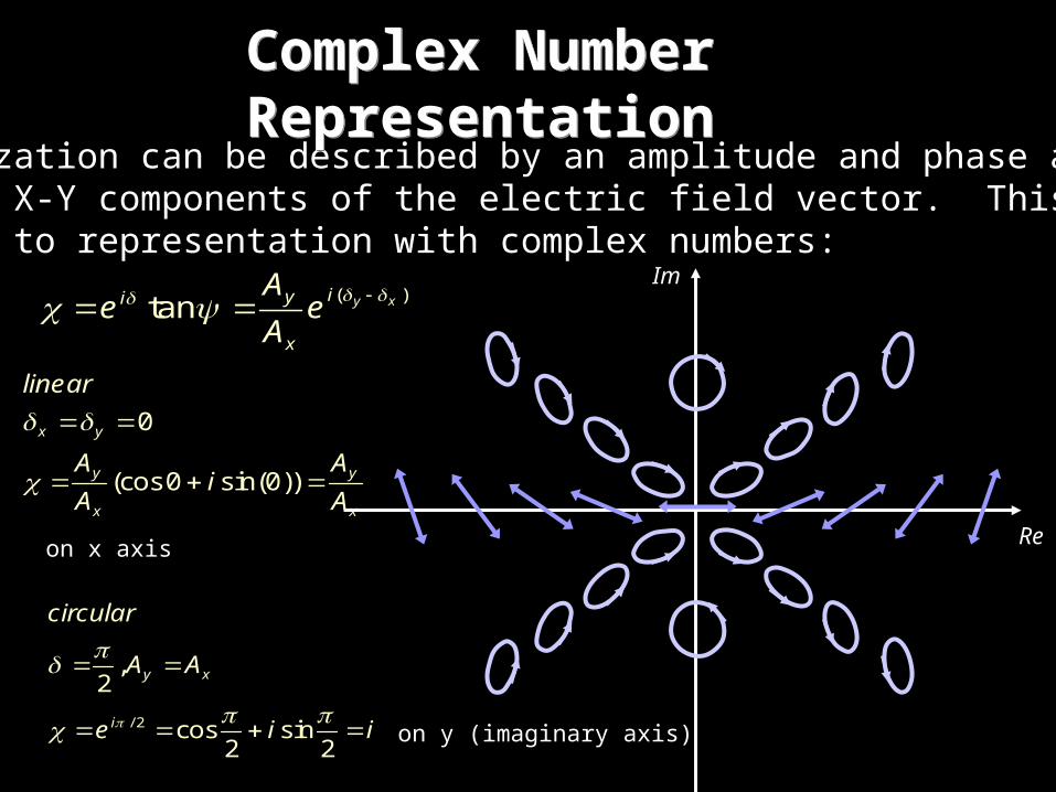
Polarization can be described by an amplitude and phase anglesof the X-Y components of the electric field vector. This lendsitself to representation with complex numbers:
( )tan y xiyi
x
Ae e
A
Complex Number RepresentationComplex Number Representation
Im
Re
0
(cos0 sin(0))
x y
y y
x x
linear
A Ai
A A
on x axis
/ 2
,2
cos sin2 2
y x
i
circular
A A
e i i
on y (imaginary axis)
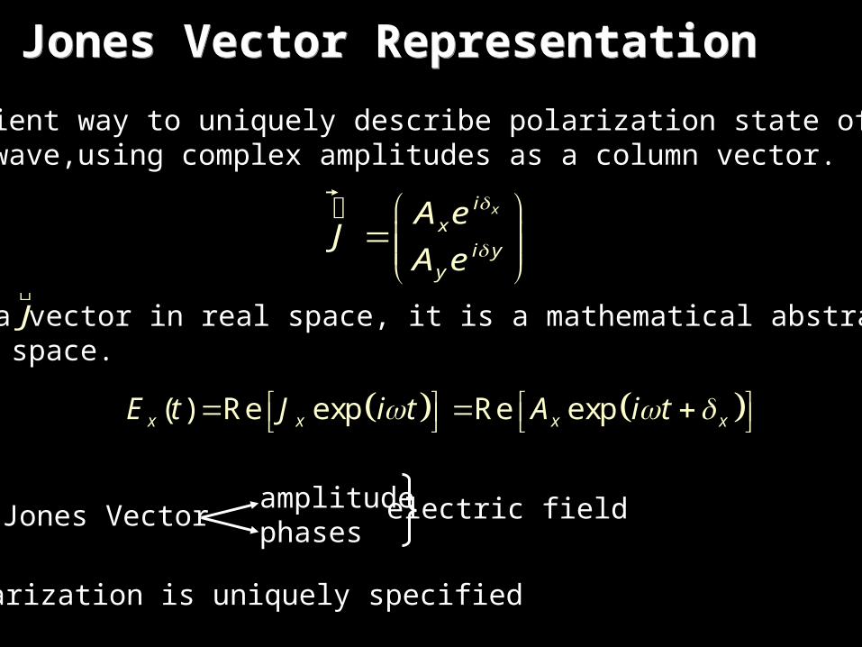
Convenient way to uniquely describe polarization state of aplane wave,using complex amplitudes as a column vector.
xix
i yy
A eJ
A e
��������������
J��������������
is not a vector in real space, it is a mathematical abstraction incomplex space.
( ) Re exp Re expx x x xE t J i t A i t
Jones Vectoramplitudephases
electric field
Polarization is uniquely specified
Jones Vector RepresentationJones Vector Representation
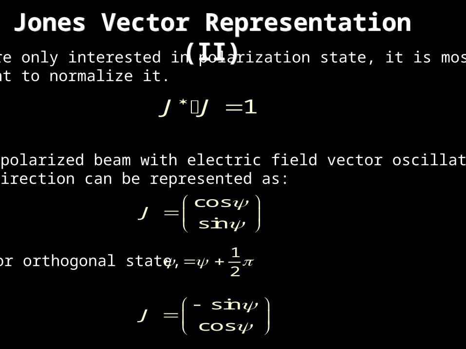
Jones Vector Representation (II)Jones Vector Representation (II)If you are only interested in polarization state, it is most convenient to normalize it.
1 J J
A linear polarized beam with electric field vector oscillating alonga given direction can be represented as:
cos
sinJ
sin
cosJ
For orthogonal state, 1
2
Jones Vector Representation (III)Jones Vector Representation (III)
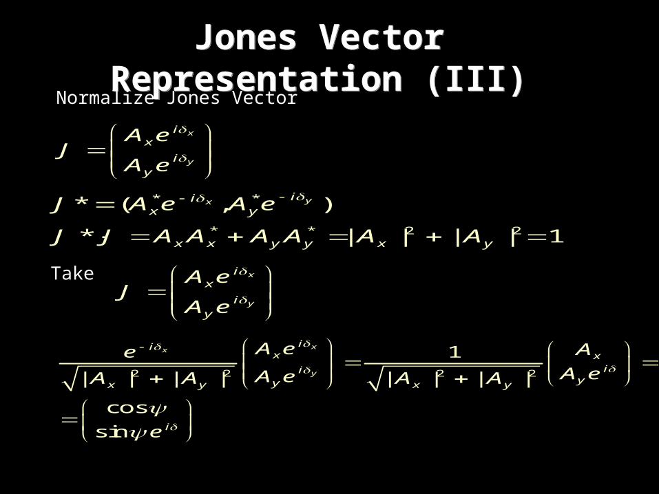
Normalize Jones Vector
x
y
ix
iy
A eJ
A e
* *
* * 2 2
* ( , )
* | | | | 1
yx iix y
x x y y x y
J A e A e
J J A A A A A A
Take x
y
ix
iy
A eJ
A e
2 2 2 2
1
| | | | | | | |
cos
sin
xx
y
iix x
iiyyx y x y
i
A e AeA eA eA A A A
e

When =0 for linear polarized light, the electric field oscillates along coordinate system, the Jones Vectors are given by:
cos 1 sin 0
sin 0 cos 1x y
For circular polarized light:/ 2
/ 2
cos 11
sin 2
cos 11
sin 2
i
i
Re i
Le i
Mutually orthogonal condition 0R L
Jones Vector Representation (IV)Jones Vector Representation (IV)The Jones matrix of rank 2, any pair of orthogonal Jones vectors can be used as a basis for the mathematical space spanned by all the Jones vectors.

Polarization Ellipse Jones Vector () () Stokes
1
0
0
1
11
12
11
12
0,0 0,0
0, / 2 / 2,0
0, / 4 / 4,0
, / 4 / 4,0
1
1
0
0
1
1
0
0
1
0
1
0
1
0
1
0
Polarization RepresentationPolarization Representation

Polarization Ellipse Jones Vector () () Stokes
21
5 i
0, / 4 / 2, / 4
1
0
0
1
11
25 i
11
2 i
11
2 i
21
210
i
i
0, / 4 / 2, / 4
1/ 2, tan 2 1 1/ 2, tan2
1 1/ 2, tan2
1 10, tan2
1 1/ 4, tan2
1 4tan , / 43
1
3/ 5
0
4 / 5
1
3/ 5
0
4 / 5
1
0
3/ 5
4 / 5
1
0
0
1
Polarization RepresentationPolarization Representation

Jones is powerful for studying the propagation of plane waveswith arbitrary states of polarization through an arbitrary sequence of birefringent elements and polarizers.
Limitations:• Applies to normal incidence or paraxial rays only• Neglects Fresnel refraction and surface reflections• Deficient polarizer modeling• Only models polarized light
Other Methods:• 4x4 Method – exact solutions
(models refraction and multiple reflections)• 2x2 Extended Jones Matrix Method
(relaxes multiple reflections for greater simplicity)
Jones Matrix LimitationsJones Matrix Limitations

We discussed monochromatic/polarization thus far.
If light is not absolutely monochromatic, the amplitude and relative phase between x and y components can vary with time, and the electric field vector will first vibrate in one ellipse and then in another. The polarization state of a polychromatic wave is constantly changing.
If polarization state changes faster than speed of observation,the light is partially polarized or unpolarized.
Optics – light of oscillation frequencies 1014s-1
Whereas polarization may change 10-s (depending on source)
Partially Polarized & Unpolarized LightPartially Polarized & Unpolarized Light
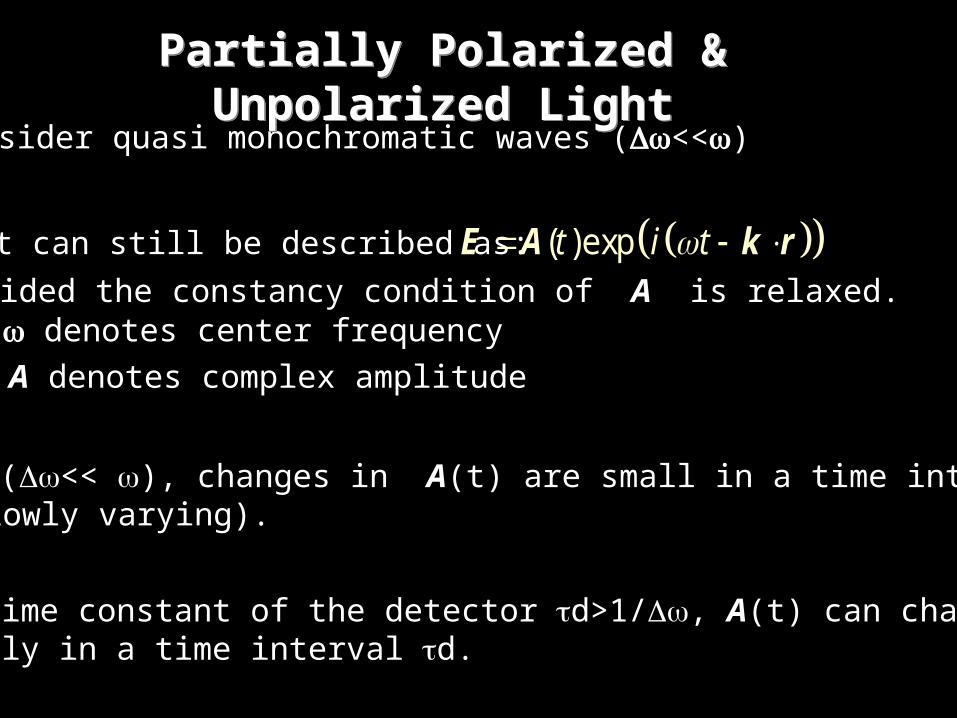
Consider quasi monochromatic waves (<<)
Light can still be described as: ( )expt i tE A k rProvided the constancy condition of A is relaxed. denotes center frequency
A denotes complex amplitude
Because (<< ), changes in A(t) are small in a time interval1/ (slowly varying).
If the time constant of the detector d>1/, A(t) can change originally in a time interval d.
Partially Polarized & Unpolarized LightPartially Polarized & Unpolarized Light

To describe this type of polarization state, must consider time averaged quantities.
S0 = <<Ax2+Ay
2>>
S1 = <<Ax2-Ay
2>>
S2 = 2<<AxAy cos>>
S3 = 2<<AxAy sin>>
Ax, Ay, and are time dependent<< >> denotes averages over time interval d that is the characteristic time constant of the detection process.
These are STOKES parameters.
Partially Polarized & Unpolarized LightPartially Polarized & Unpolarized Light

Note: All four Stokes Parameters have the same dimension of intensity.
They satisfy the relation:
2 2 2 20 1 2 3S S S S
the equality sign holds only for polarized light.
Stokes ParametersStokes Parameters

Example: Unpolarized light
No preference between Ax and Ay (Ax=Ay), random
S0 = <<Ax2+Ay
2>>=2<<Ax2>>
S1= <<Ax2-Ay
2>>=S2,3=2<<AxAy cos>>=2<<AxAy sin>>=
since is a random functionof time
if S0 is normalized to 1, the Stokes vector parameter isfor unpolarized light.
1
0
0
0
Example: Horizontal Polarized Light Ay=0, Ax=1
S0=<<Ax2>>=1
S1=<<Ax2>>=1
S2,3=2<<AxAy cos>>=2<<AxAy sin>>=
1
1
0
0
Stokes ParametersStokes Parameters
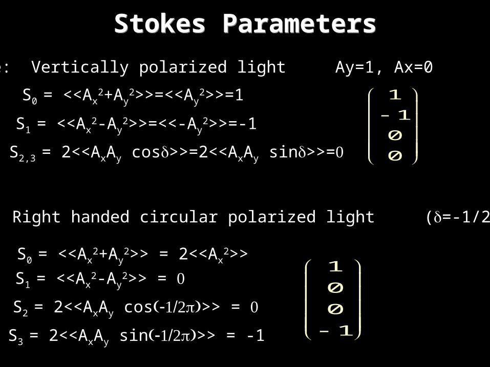
Example: Vertically polarized light Ay=1, Ax=0
S0 = <<Ax2+Ay
2>>=<<Ay2>>=1
S1 = <<Ax2-Ay
2>>=<<-Ay2>>=-1
S2,3 = 2<<AxAy cos>>=2<<AxAy sin>>=
1
1
0
0
Example: Right handed circular polarized light (=-1/2) Ax=Ay
1
0
0
1
S2 = 2<<AxAy cos>> =
S0 = <<Ax2+Ay
2>> = 2<<Ax2>>
S1 = <<Ax2-Ay
2>> =
S3 = 2<<AxAy sin>> = -1
Stokes ParametersStokes Parameters

Example: Left handed circular polarized light (=1/2) Ax=Ay
S2 = 2<<AxAy cos>> =
S0 = <<Ax2+Ay
2>> = 2<<Ax2>>
S1 = <<Ax2-Ay
2>> =
S3 = 2<<AxAy sin>> = 1
Degree of polarization:
12 2 2 2
1 2 3
0
S S S
S0 1
Unpolarized S12 = S2
2 = S32 =
Polarized S12+S2
2+S32 = 1
useful for describing partially polarized light
Stokes ParametersStokes Parameters
1
0
0
1

Jones Matrix Method (I)Jones Matrix Method (I)
Z-axis
Y-axiss
X-axis
f
• The polarization state in a fixed lab axis X and Y:
x
y
VV
V
• Decomposed into fast and slowcoordinate transform:
cos sin
sin cosx xs
y yf
V VVR
V VV
(notation: fast (f) and slow (s) component of the polarization state)
rotation matrix
• If ns and nf are the refractive indices associated with the pro-pagation of slow and fast components, the emerging beam has the polarization state: 2
exp 0
20 exp
ss s
ff f
in dV V
VV in d
Where d is the thickness and isthe wavelength

• For a “simple” retardation film, the following phase changes occur:
2
s fn n d
1 2
2 s fn n d
/ 2
/ 2
2exp 0
20 exp
2exp 0
2 2
20 exp
2 2
0
0
ss s
ff f
s f s f
s
s f s f f
isi
i
in dV V
VV in d
n n n ni d
V
n n n n Vi d
Vee
e V
f
(relative phase retardation) (mean absolute phase change)
Jones Matrix Method (II)Jones Matrix Method (II)
• Rewriting previous retardation equation:

Jones Matrix Method (III)Jones Matrix Method (III)
•The Jones vector of the polarization state of the emerging beam in the X-Y coordinate system is given by transforming back to the S-F coordinate system.
cos sin
sin cosx s
y f
V V
V V
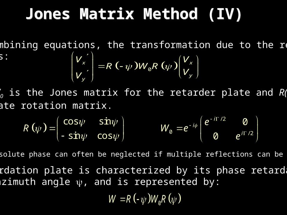
• By combining equations, the transformation due to the retarder plate is:
0x x
yy
V VR W R
VV
where W0 is the Jones matrix for the retarder plate and R() is thecoordinate rotation matrix.
cos sin
sin cosR
/ 2
0 / 2
0
0
ii
i
eW e
e
(The absolute phase can often be neglected if multiple reflections can be ignored)
A retardation plate is characterized by its phase retardation and its azimuth angle , and is represented by:
0W R W R
Jones Matrix Method (IV)Jones Matrix Method (IV)

Polarizer with transmissionaxis oriented to X-axis
0
1 0
0 0iP e
’ is due to finite optical thicknessof polarizer.
If polarizer is rotated by about 0P R P R
ignoring ’ polarizers transmittinglight with electric field vectors tox and y are:
1 0
0 0xP
0 0
0 1yP
Jones Vector
cos
sin
11
2 i
11
2 i
cos sin
sin cos
a ib
a ib
cos sin
sin cos
a ib
a ib
Y-axis
X-axis
E
ab
ab
Polarization State
ExamplesExamples
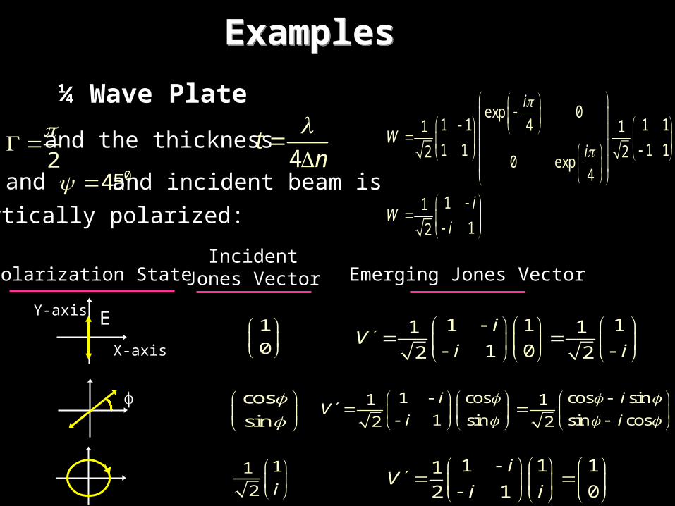
¼ Wave Plate
2
and the thickness
4t
n
045 and and incident beam is
vertically polarized:
exp 01 1 1 141 1
1 1 1 12 20 exp
4
11
12
i
Wi
iW
i
1
0
1 11 1
12 2
iV
i i
IncidentJones Vector
1
0
11
2 i
Y-axis
X-axis
E
Polarization State
ExamplesExamples
cos
sin
Emerging Jones Vector
cos cos sin
s
11
in sin co
1
1 2 s2
i
i
iV
i
11 11
1 02
iV
i i

y
xc-axis
c-axis
c-axis
c-axis
450
Jones MatricesWave Plates
2
e on n d
/ 2
/ 2
0
0
i
i
eW
e
/ 2
/ 2
0
0
i
i
eW
e
cos sin2 2
sin cos2 2
iW
i
/ 2
/ 2
0
0
i
i
eW R R
e
/ 2
/ 2
cos sin cos sin0
sin cos sin cos0
i
i
eW
e
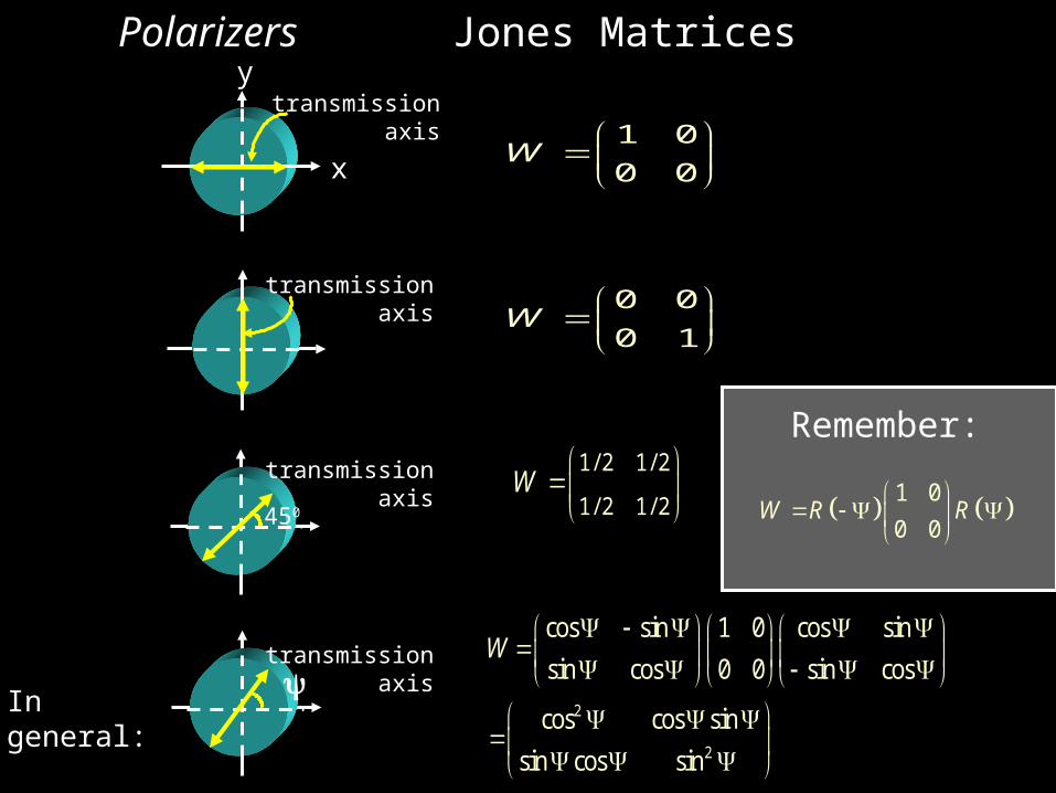
Remember:
Ingeneral:
y
x
450
transmissionaxis
1 0
0 0W
0 0
0 1W
1/ 2 1/ 2
1/ 2 1/ 2W
2
2
cos sin 1 0 cos sin
sin cos 0 0 sin cos
cos cos sin
sin cos sin
W
Jones MatricesPolarizers
transmissionaxis
transmissionaxis
transmissionaxis
Ingeneral:
1 0
0 0W R R
Remember:
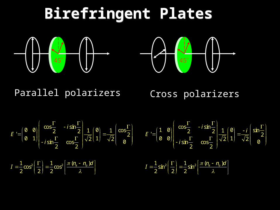
Birefringent PlatesBirefringent Plates
45 45
Parallel polarizers Cross polarizers
2 2
cos sin1 0 0 sin12 2' 20 0 12 2 0sin cos
2 2
1 1 ( )sin sin2 2 2
e o
ii
E
i
n n dI
2 2
cos sin0 0 0 cos1 12 2' 20 1 12 2 0sin cos
2 2
1 1 ( )cos cos2 2 2
e o
iE
i
n n dI

Poincare’s Representatives Method
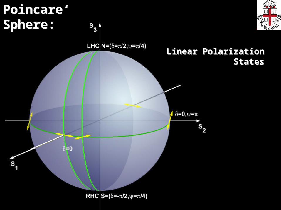
Poincare’ Sphere:Poincare’ Sphere:
Linear Polarization States
Linear Polarization States

Poincare’ Sphere:Poincare’ Sphere:
Elliptic Polarization States
Elliptic Polarization States

Polarization Conversion:Polarization Conversion:


Polarization Conversion:Polarization Conversion:
Z-axis
Y-axis
s
X-axis
f
Some Examples
TN LCD Formulations
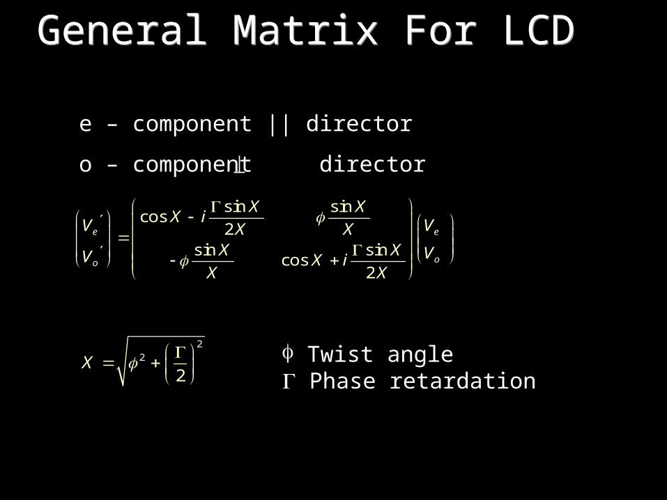
General Matrix For LCDGeneral Matrix For LCD
e – component || director
o – component director
sin sincos
2sin sin
cos2
e e
oo
X XX iV VX X
X X VV X iX X
22
2X
Twist angle Phase retardation

• Consider light polarized parallel to the slow axis of a twisted LC twisted structure:
1 mode
0e
o
VE
V
• Then, the output polarization will be:
sincos
2sin
e
o
XX iV X
XVX
22with
2X
Adiabatic WaveguidingAdiabatic Waveguiding
90° Twist90° Twist

• Notice that for TN displays since << (twist angle muchsmaller than retardation ):
• Then the outputpolarization reduces to:
/ 2sin
cos2
sin 0
ie
o
XX iV eX
XVX
which means that the electric field vector “follows” the nematicdirector as beam propagates through medium – it rotates –
Adiabatic WaveguidingAdiabatic Waveguiding
2 0.23 202
18.40.5
mnd
m

• Consider twisted structure between a pair of parallel polarizersand consider e-mode operation.
• The transmission after the second polarizer:
2 2
2
sin 11
2 1
uT
u
2
2 2
u nd
90º Twisted Nematic (Normal Black)
90º Twisted Nematic (Normal Black)
sin sincos
0 0 1 0 11 20 1 sin sin 0 0 12 cos
2
e
o
X XX iV X X
X XV X iX X
e-mode input

Transmission of Normal BlackTransmission of Normal Black
0
0.1
0.2
0.3
0.4
0.5
0 2 4 6 8 10 12 14u
T (
%)
2d nu
first minimum
3u 15
35
second minimum
third minimum

• Consider twisted structure between a pair of parallel polarizersand consider e-mode operation.
• The transmission after the second polarizer:
2 2
2
sin 11 1
2 2 1
uT
u
2
2 2
u nd
sin sincos
1 0 1 0 11 20 0 sin sin 0 0 12 cos
2
e
o
X XX iV X X
X XV X iX X
e-mode input
Normal White Mode (I)Normal White Mode (I)

0
0.1
0.2
0.3
0.4
0.5
0 2 4 6 8 10 12 14u
T (
%)
2d nu
3u 1535
Normal White Mode (II)Normal White Mode (II)

En
(n)
n n
n n
n n n
n n
E
E E
E E E
E E E
E
0z /10z d
6 /10z d
5 /10z d4 /10z d3 /10z d
2 /10z d
9 /10z d
8 /10z d7 /10z d
z d
Y-axis
X-axis

z
d
A
F B D
C
1n
1n
e
o
Phase Retardation at Oblique
Incidence: Complicating Matters
Phase Retardation at Oblique
Incidence: Complicating Matters

Vital to understanding LCD’s and their viewing angle solutions:
• Linear, circular, elliptical polarization
• Jones Vector
• Stokes Parameters
• Jones Matrixes
• Adiabatic Waveguiding
• Extended Jones and 4x4 Methods
Summary of OpticsSummary of Optics