review of dc circuit breakers for submarine applications · pdf filecorporate enabling...
TRANSCRIPT

UNCLASSIFIED
Review of DC Circuit Breakers for Submarine Applications
Wang Y. Kong
Maritime Platforms Division Defence Science and Technology Organisation
DSTO-TN-1074
ABSTRACT The Defence Science and Technology Organisation (DSTO) has undertaken a review of direct current (dc) circuit breakers for submarines as a deliverable under the System Integration (SI) Corporate Enabling Research Program (CERP). This review is conducted to support the evaluation of dc circuit breaker options for future submarines.
RELEASE LIMITATION
Approved for public release
UNCLASSIFIED

UNCLASSIFIED
Published by Maritime Platforms Division DSTO Defence Science and Technology Organisation 506 Lorimer St Fishermans Bend, Victoria 3207 Australia Telephone: (03) 9626 7000 Fax: (03) 9626 7999 © Commonwealth of Australia 2012 AR-015-254 March 2012 APPROVED FOR PUBLIC RELEASE
UNCLASSIFIED

UNCLASSIFIED
Review of DC Circuit Breakers for Submarine Applications
Executive Summary The Defence Science and Technology Organisation (DSTO) have undertaken a review of direct current (dc) circuit breakers for submarines as a deliverable under the System Integration (SI) Corporate Enabling Research Program (CERP). This review is conducted to support evaluation of dc circuit breaker options for future submarines. A circuit breaker is a device capable of making, carrying and breaking currents under normal circuit conditions and also making, carrying for a specified time and breaking currents under specified abnormal circuit conditions. Circuit breakers are installed in submarines to protect crew and plant equipment against large currents caused by electrical faults. With advancements in battery technologies, and the increased use of power electronic converters, the magnitude of fault currents in a future submarine is likely to be substantially larger than that of existing submarines. This report surveys existing and developmental dc circuit breaker technologies to evaluate their ability to handle fault currents in a future submarine. Four major types of technology that are relevant to this application have been considered, broken into two categories:
Arc based circuit breakers (electro-mechanical) o Air arc chute circuit breakers o Vacuum circuit breakers
Solid state and hybrid circuit breakers o Solid state circuit breakers o Solid state and electro-mechanical hybrid circuit breakers
This review found that the wide availability of mature air arc chute circuit breakers lowers the risk they pose for application in a future submarine. However their slow interruption speeds allow substantial fault currents to develop, introducing potential safety risks. Alternatively vacuum circuit breakers offer a number of distinct technical advantages over arc-chute circuit breakers such as faster interruption speed and low operating noise, however lack of mature technology and research and development for this application is likely to hinder their adaptation in future low voltage dc applications. Solid state circuit breakers replace the electro-mechanical contacts with semiconductor devices, allowing high speed interruption of current which is beneficial in stopping the
UNCLASSIFIED

UNCLASSIFIED development of large fault currents. However, this is achieved at a cost of higher on-state losses. Alternately hybrid circuit breakers use a combination of semiconductor and electro-mechanical switches to achieve low on-state losses and fast current interruption speeds with minimal wear to the electro-mechanical contact. However, developments of these two technologies are still in their early stages, and commercial and practical applications remain limited. DSTO are currently aware of conflicting views from major industry competitors regarding the magnitude and characteristic of predicted fault currents in future submarines using alternative battery technologies and increased quantities of power electronic conversion. Based on discussions in this report, DSTO make the following comment and recommendation: Comment 1: DSTO is aware of conflicting points of view concerning the ability of current circuit breaker technologies to adequately cope with faults in dc power systems of future submarines with advanced battery systems. Recommendation 1: DSTO recommends that detailed fault current studies be conducted to determine whether existing circuit breaker technologies have sufficient fault current breaking ability to meet the requirements of a future submarine.
UNCLASSIFIED

UNCLASSIFIED
Author
Wang Y. Kong Maritime Platforms Division Wang Kong received the B.Sc. degree in computer science and the B.E. degree in electrical and computer systems engineering in 2006 from Monash University, Clayton, Vic., Australia. He has recently submitted his thesis entitles “Decentralised Control of a Cascaded Modular Multilevel Converter” towards the Ph.D. degree at Monash University, Clayton, Vic, Australia. He is currently an electrical research engineer in the Propulsion and Energy Systems group of the Maritime Platforms Division of DSTO.
____________________ ________________________________________________
UNCLASSIFIED

UNCLASSIFIED
UNCLASSIFIED
This page is intentionally blank

UNCLASSIFIED DSTO-TN-1074
Contents
LIST OF FIGURES ..................................................................................................................IV
ACRONYMS AND ABBREVIATIONS............................................................................ VII
1. INTRODUCTION............................................................................................................... 1 1.1 Scope ........................................................................................................................... 1 1.2 Overview of Circuit Breakers ................................................................................. 1 1.3 Protection Requirements of a Submarine Power Distribution System.......... 3 1.4 Design Parameters for a Circuit Breaker .............................................................. 6
1.4.1 Current Ratings........................................................................................ 6 1.4.2 Voltage Rating.......................................................................................... 6 1.4.3 Characteristic Curve, Break Time and Control Mechanisms............ 7 1.4.4 Endurance................................................................................................. 7 1.4.5 Maintainability and Installation ............................................................ 8 1.4.6 Environmental Factors............................................................................ 9
1.5 Key Circuit Breaker Types ...................................................................................... 9 1.5.1 Air Arc Chute Circuit Breaker ............................................................... 9 1.5.2 Vacuum Circuit Breaker ....................................................................... 10 1.5.3 Air Blast Circuit Breaker....................................................................... 10 1.5.4 SF6 Circuit Breaker ................................................................................ 10 1.5.5 Solid State and Hybrid Circuit Breaker.............................................. 11
1.6 Summary................................................................................................................... 11
2. ARC BASED DC CIRCUIT BREAKERS ...................................................................... 12 2.1 Electric Arc ............................................................................................................... 12
2.1.1 Formation of Electric Arc in Air Due to Opening of an Electrical Contact .................................................................................................... 13
2.1.2 Structure of Electric Arc in Air ............................................................ 13 2.1.3 Application of Electric Arcs in DC Circuit Breakers ........................ 15
2.2 Air Arc Chute Circuit Breaker .............................................................................. 16 2.2.1 Cold Cathode Arc Chute ...................................................................... 16 2.2.2 Insulated Plate Arc Chute .................................................................... 19 2.2.3 Commercial Air Arc chute Circuit Breaker for Submarine
Application............................................................................................. 20 2.3 Vacuum Circuit Breaker ........................................................................................ 23
2.3.1 Arc in Vacuum....................................................................................... 23 2.3.2 Structure of a Vacuum Circuit Breaker .............................................. 25
2.4 Sensitivity to Shock and Vibration ..................................................................... 27 2.5 Summary................................................................................................................... 28
3. SOLID STATE AND HYBRID CIRCUIT BREAKERS.............................................. 29 3.1 Power Semiconductor Devices ............................................................................. 29 3.2 Topologies for Solid State Circuit Breakers ...................................................... 30
UNCLASSIFIED i

UNCLASSIFIED DSTO-TN-1074
3.3 Hybrid Circuit Breaker .......................................................................................... 34 3.4 Reliability of Solid State and Hybrid Circuit Breaker .................................... 35 3.5 Practical Solid State and Hybrid Circuit Breakers ........................................... 37 3.6 Applicability and Future Trend ........................................................................... 37 3.7 Summary................................................................................................................... 38
4. CONCLUSION .................................................................................................................. 40
5. REFERENCES .................................................................................................................... 43
APPENDIX A: TECHNICAL SPECIFICATION OF A CIRCUIT BREAKER .......... 47 A.1. Current Ratings............................................................................... 47
A.1.1 Rated Uninterrupted Current (Iu) .................................. 47 A.1.2 Rated Short-Circuit Making Capacity (Icm)................... 47 A.1.3 Rated Service Short-Circuit Breaking Capacity (Ics) .... 47 A.1.4 Rated Ultimate Short-Circuit Breaking Capacity (Icu). 47 A.1.5 Rated Short-Time Withstand Current (Icw) ................... 47
A.2. Voltage Ratings............................................................................... 48 A.2.1 Rated Operational Voltage (Ue) ..................................... 48 A.2.2 Rated Insulation Voltage (Ui) ......................................... 48 A.2.3 Rated Impulse Withstand Voltage (Uimp) ..................... 48
A.3. Thermal-Magnetic and Electronics Controller for Power Circuit Breakers .............................................................................. 48
A.4. Endurance ........................................................................................ 49 A.5. Environment Factors for a Circuit Breaker................................ 49
A.5.1 Ambient Operating Temperature.................................. 49 A.5.2 Air Pressure ...................................................................... 50 A.5.3 Humidity and Pollutants ................................................ 50
APPENDIX B: SEMICONDUCTOR DEVICES............................................................. 52 B.1. Device Breakdown/Blocking Voltage ........................................ 52 B.2. Current Ratings............................................................................... 52 B.3. Practical Switching Characteristics of a Semiconductor
Device ............................................................................................... 52 B.4. Operating Losses of a Semiconductor Device .......................... 53
APPENDIX C: SEMICONDUCTORS DEVICES FOR SOLID STATE CIRCUIT BREAKERS ................................................................................................ 55 C.1. Diode ................................................................................................ 55 C.2. Thyristor........................................................................................... 55 C.3. Gate Turn-Off Thyristor (GTO) .................................................. 56 C.4. Integrated Gate-Commutated Thyristor (IGCT) ...................... 56 C.5. Insulated Gate Bipolar Transistor (IGBT)................................. 57
APPENDIX D: COPYRIGHT............................................................................................. 58 D.1. ABB Asea Brown Boveri Ltd ........................................................ 58
UNCLASSIFIED ii

UNCLASSIFIED DSTO-TN-1074
D.2. The Institution of Engineering and Technology...................... 58 D.3. CRC Press LLC – Taylor & Francis Group LCC - Books......... 58
UNCLASSIFIED iii

UNCLASSIFIED DSTO-TN-1074
List of Figures
Figure 1 Basic dc circuit containing a circuit breaker.............................................................. 2 Figure 2 Basic dc circuit with short circuit fault ...................................................................... 2 Figure 3 Major components of the electrical system in a conventional diesel-electric
submarine ...................................................................................................................... 4 Figure 4 Example typical time-current characteristic curve of a thermal-magnetic
trigger system for a circuit breaker ............................................................................ 8 Figure 5 Time-current characteristic curve of a electronic controlled circuit breaker
[16]................................................................................................................................... 9 Figure 6 Formation and rapture of molten metal bridge [2], T = temperature, Tm =
melting temperature of metallic contact, Tbl = boiling temperature of material in contact13
Figure 7 Electric arc constricted at the contacts in air and the corresponding voltage distribution [2]................................................................................................. 14
Figure 8 Energy balance in an electric arc [2] ........................................................................... 16 Figure 9 Structure of arcing contact of a arc chute circuit breaker [15], © The IET ............ 17 Figure 10 Structure of a dc circuit breaker with cold cathode arc chute [15], © The
IET ................................................................................................................................... 18 Figure 11 (a) Cold cathode arc chute and arc runner, (b) Cold cathode arc chute
plate [15], © The IET..................................................................................................... 18 Figure 12 Interruption characteristic of a cold cathode arc chute circuit breaker [18],
where Ip = short-circuit making current of circuit breaker, Icn = short circuit current if fault is not interrupted, Ua = maximum arc voltage of breaker, Un = voltage across breaker, T = time constant of system, to = instant of beginning of short-circuit, ts = instant of circuit breaker contact separation, ta = instant of quenching of the fault current19
Figure 13 Insulated plate arc chute circuit breaker [15], © The IET....................................... 20 Figure 14: ABB EMax DC circuit breaker [18] ............................................................................... 21 Figure 15 Pole and bus bar configuration of a series of commercial dc circuit
breakers at 500-1000V [45] ........................................................................................... 22 Figure 16 Operating mechanisms of a vacuum interrupter[47] .............................................. 25 Figure 17 Vacuum contact structure for different magnetic fields: (a) cup contacts
for radial field; (b) spiral contacts for radial field; (c) third of a winding for axial field [2] .................................................................................................................. 26
Figure 18 Medium-voltage vacuum circuit-breaker, 1, breaker mechanism housing; 1.1, front panel, removable; 12 insulating material pole tube; 13, upper breaker terminal; 14, lower breaker terminal; 15, vacuum interrupter; 16, roller contact; 17, contact pressure spring; 18, insulated coupling rod; 19, opening spring; 20, shift lever pair [2] ....................................................................... 26
Figure 19 DC circuit with vacuum breaker and high frequency current source, where U is the circuit dc voltage source, R and L are load resistance and inductance, Cc and Lc are the capacitance and inductance of high frequency current source, and CBc and CBm are the high frequency current source and main circuit breaker [50] ............................................................ 27
UNCLASSIFIED iv

UNCLASSIFIED DSTO-TN-1074
Figure 20 (a) Circuit symbol of a metal-oxide varistor (MOV), (b) typical current-voltage characteristic of a MOV.................................................................................. 31
Figure 21 (a) IGCT based simple bi-directional solid state circuit breaker [24], (b) IGBT based simple bi-directional solid state circuit breaker [27] .......................... 32
Figure 22 (a) IGCT based medium voltage bi-directional solid state circuit breaker [23], (b) IGCT based medium voltage bi-directional solid state circuit breaker [23], (c) GTO based bi-directional solid state circuit breaker [62............ ]32
Figure 23 Solid state circuit breaker with capacitor aided turn-off [65] ................................. 33 Figure 24 (a) GTO ac hybrid circuit breaker [66], (b) IGBT bi-directional Hybrid dc
circuit breaker [67], (c) IGCT bi-direction hybrid dc circuit breaker [30] ............. 35 Figure 25 Paschen curve for air [2] .............................................................................................. 51 Figure 26 Generic switching characteristic of semiconductor devices (linearised): (a)
simple switching circuit, (b) switching signal, (c) voltage and current waveform,(d) instantaneous switch power loss....................................................... 53
Figure 27 Circuit symbol and ideal characteristic of (a) diode, (b) thyristor, (c) GTO, (d) IGCT, (e) IGBT......................................................................................................... 56
Figure 28 Picture of a standard IGCT [85] .................................................................................. 57
UNCLASSIFIED v

UNCLASSIFIED DSTO-TN-1074
This page is intentionally blank
UNCLASSIFIED vi

UNCLASSIFIED DSTO-TN-1074
Acronyms and Abbreviations
ac Alternating Current dc Direct Current DSTO Defence Science and Technology Organisation EMI Electromagnetic Interference GTO Gate Turn-Off Thyristor IEEE Institute of Electrical and Electronics Engineers IGBT Insulated Gate Bipolar Transistor IGCT Integrated Gate-Commutate Thyristor MOSFET Metal Oxide Semiconductor Field Effect Transistor MOV Metal Oxide Varistor MPD Maritime Platform Division RAN Royal Australian Navy SCR Silicon Controlled Rectifier SF6 Sulfur hexafluoride SSK Diesel-electric submarine TRL Technology Readiness Level
UNCLASSIFIED vii

UNCLASSIFIED DSTO-TN-1074
UNCLASSIFIED viii
This page is intentionally blank

UNCLASSIFIED DSTO-TN-1074
1. Introduction
The Defence Science and Technology Organisation (DSTO) has undertaken a review of direct current (dc) circuit breakers for submarines as a deliverable of the Systems Integration (SI) Corporate Enabling Research Program (CERP). 1.1 Scope
This review is conducted to support the evaluation of dc circuit breaker options for future submarines. The following technologies have been considered:
Arc based circuit breakers (electro-mechanical) o Air arc chute circuit breakers o Vacuum Circuit breakers
Solid state and hybrid circuit breakers o Solid state circuit breakers o Solid state and electro-mechanical hybrid circuit breakers
This chapter introduces the basic functions and principles of a circuit breaker for dc power distribution systems. An overview of aims and requirements for circuit breakers in a submarine power distribution system will then be presented to serve as background for this report. A review of the major types of circuit breaker technologies, including their working principles, potential applications and future development trends will also be presented. 1.2 Overview of Circuit Breakers
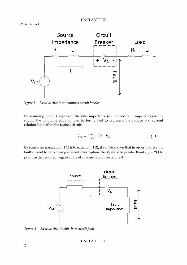
A circuit breaker is a device “capable of making, carrying and breaking currents under normal circuit conditions and also making, carrying for a specified time and breaking currents under specified abnormal circuit conditions such as those of short-circuit” [1]. A circuit breaker is installed in the path of current flow as shown in Figure 1. During the current interruption process the breaker opens causing a dynamic increase in its dielectric strength (a measure of a material’s insulation strength or impedance). This causes the resistance of the circuit breaker to increase, which forces a large voltage to develop across the circuit breaker and helps to drive the fault current to zero. These devices are commonly used in power distribution systems (both dc and ac) of all sizes to ensure safety of personnel and plant equipment. Function of a circuit breaker during a fault can be illustrated by a bus to bus fault (unintended connection between a system’s positive and negative voltage buses) as shown in Figure 1, where VDC is the dc voltage source (a combination of generators and batteries), RS and LS represent the source impedance of the power source (resistance and inductance respectively), RL and LL represent the load resistance and inductance (both stray circuit effects and actual load), VB is the voltage across the breaker and I is the current flowing in the circuit. If a short circuit event occurs in this system, the circuit as viewed by the voltage source becomes that shown in Figure 2. The impedance of the circuit is likely to be substantially reduced, and a large fault current can flow. During a fault, the magnitude of the current is only limited by the combined source and fault impedance.
UNCLASSIFIED 1
UNCLASSIFIED DSTO-TN-1074
Fault
Figure 1 Basic dc circuit containing a circuit breaker
By assuming R and L represent the total impedance (source and fault impedance) in the circuit, the following equation can be formulated to represent the voltage and current relationship within the faulted circuit:
BDC VRIdt
dILV (1.1)
By rearranging equation (1.1) into equation (1.2), it can be shown that in order to drive the fault current to zero during a circuit interruption, the VB must be greater than to
produce the required negative rate of change in fault current [
RIVDC 2-4].
Figure 2 Basic dc circuit with short circuit fault
UNCLASSIFIED 2

UNCLASSIFIED DSTO-TN-1074
BDC VRIVLdt
dI
1 (1.2)
Equation (1.2) also shows that the size of load and source inductance is inversely proportional to the rate of change of current; hence the time it takes to clear a fault depends on both the acceptable magnitude of voltage across the circuit breaker and size of inductive load in the system. Once the current within the circuit drops to zero, a circuit breaker should maintain its high dielectric strength [4] (essentially acting as a good insulator) to avoid further current flow until it is retriggered to close and resume normal operation. As an aside, during normal operation, VB should be as close to zero as possible to minimise the on-state losses of the circuit breaker, since on-state losses do not contribute to any useful work and is usually dissipated as wasted heat. From these discussions it can be seen that there are three primary objectives for any circuit breaker. Firstly a circuit breaker should allow nominal load current to flow with as little on-state losses as possible. Secondly, a circuit breaker introduces an electrical insulator into the circuit to stop the flow of current (fault or otherwise). Thirdly, it also dissipates the stored energy within the circuit inductance (including both load and stray inductance), thus eliminating large voltage overshoots caused by sudden interruption to current flow. Most electro-mechanical circuit breakers achieve these objectives by opening a mechanical contact. This basically utilises the comparative high insulation strength of substances such as air, vacuum and sulfur hexafluoride (SF6) that are introduced between the opened contact to create the required insulator. The opening of an electro-mechanical contact also creates an electrical arc between the contact surfaces, which helps to dissipate stored energy in the circuit inductance. In solid state circuit breakers, where the mechanical contact is replaced by power semiconductor devices, the insulator is introduced by “opening” these devices. In these systems, stored energy is dissipated through external circuit elements such as metal oxide varistors. 1.3 Protection Requirements of a Submarine Power Distribution System
A dc power distribution system is used in most conventional diesel-electric submarines (SSK). Major components of this system consist of diesel generators, battery banks (typically lead acid batteries), propulsion motors and hotel loads (air conditioning system, weapon system, etc.). A typical layout of this power distribution system is shown in Figure 3 [5]. The power rating of a dc distribution system for an SSK (such as RAN operated Collins Class submarines) is typically in the multi-megawatts range with dc bus voltage as high as 1000 V, and nominal operating current as high as a few kilo-amperes.
UNCLASSIFIED 3

UNCLASSIFIED DSTO-TN-1074
One of the primary objectives of any power system is to supply power to loads, while ensuring the safety of its operator and protecting installed equipment, which is particularly important during a fault condition. In a submarine the causes of an electrical fault can range from insulation failure in motors and generators, failure of equipment and flood. Short circuit faults in a submarine can generally be grouped into two categories – the double line to ground fault, where unintended connection is made between line and ground (usually the hull of the submarine, not water); and the bus to bus fault. These faults cause electrical shorts within the system, which as illustrated in section 1.2 can cause a sustained high magnitude fault current to flow, leading to uncontrolled electric arcs that can damage personnel and plant. In the power distribution system of a submarine circuit breakers play a vital role in ensuring safety of personnel and plant equipment in the event of a fault. In Australian [1] and Institute of Electrical and Electronics Engineers (IEEE) standards [6], circuit breakers suitable for this application are defined as low voltage power dc circuit breakers. Low voltage power dc circuit breakers cover all dc power circuit breakers with rated voltage below 3,200 V dc. From the viewpoint of a circuit breaker designer, dc distribution systems such as those in SSKs pose some different challenges to circuit breakers in ac systems. In ac circuit breakers, load current can be interrupted at natural sinusoidal zero crossings, which helps to minimise the electric arc produced. In a dc system no such zero crossing exists, therefore the contact of a dc circuit breaker is exposed to substantially larger fault current during a circuit interruption. This means circuit breakers in a dc system must be specifically designed to cope with the large electric arc produced. One of the key considerations for a circuit breaker is the magnitude of the load and fault currents, as this determines the steady state (on state losses) and interruption (severity of arcing) requirements of the breaker. In submarines the magnitude of the load current flowing
Figure 3 Major components of the electrical system in a conventional diesel-electric submarine
UNCLASSIFIED 4

UNCLASSIFIED DSTO-TN-1074
through a circuit breaker is relatively easy to determine, but the magnitude of maximum fault current is harder to calculate. From previous discussions, the magnitude of fault current is largely controlled by the fault and source impedance during a fault. The magnitude of the fault impedance largely depends on the circuit condition during a fault event, and can vary from approximately zero in a direct short circuit, to a value similar to the nominal load [7]. Source impedance of different energy sources in a submarine can also vary significantly, for example a generator generally has significant source impedance, while the source impedance of a battery bank is generally much smaller. Hence in a submarine, accidental shorting located close to the battery bank (low fault impedance) represents the worse case scenario, while the result of faults such as insulation failure in a generator is generally less significant (strictly from a fault current interruption point of view). The magnitude of the source impedance and the maximum fault current that the onboard batteries can generate during a fault becomes a critical consideration for the rating of circuit breakers in this application. With low internal impedance and high power density, there is potential for significant fault current to flow if advanced battery systems (e.g. lithium ion based batteries) are installed in a future submarine. DSTO is aware of conflicting schools of thought on the predicted magnitude and characteristics of fault currents in such systems. One school of thought is that the magnitude and rate of rise of the fault current will be of a similar level to an existing submarine. This allows currently available circuit breaker technologies to be applied with little or no modification. Another school of thought expects the fault current to be significantly larger, thus requiring new system architectures to limit the predicted fault current. This might also require circuit breakers with significantly improved current rating, such that they can cope with the increased fault current. While it is almost certain that the fault current in a future submarine will be at least similar in magnitude to that of an existing SSK, it remains unclear as to whether the fault current will be significantly larger as predicted by some experts. The expected magnitude of possible fault currents will directly affect the current rating and required breaking characteristics of the circuit breakers used. Comment 1: DSTO is aware of conflicting points of view concerning the ability of current circuit breaker technologies to adequately cope with faults in dc power systems of future submarines with advanced battery systems. Another key consideration is the interruption speed of the circuit breaker; which needs to be sufficiently fast to limit the adverse effects of a fault in the dc distribution system of a submarine. The rate of rise of fault current is primarily controlled by the total fault impedance in the system. Hence in a future submarine with advanced battery systems where the source impedance is expected to be low, the magnitude and the rate of rise of fault currents might be larger than those in existing submarines. Circuit breakers with high interruption speed can interrupt fault currents before they fully develop, thereby limiting the maximum possible fault current and reducing the stress on the rest of the system. The likely increased use of power electronic converters in the future submarine [8-11] can also increase the interruption speed and rated fault current requirements for circuit breakers. Power electronic converters often have large input and output filter and stabilising capacitors. During a short circuit fault these capacitors can rapidly discharge their stored energy into the fault, further increasing the magnitude of the fault current [9, 11]. While the duration of the
UNCLASSIFIED 5
UNCLASSIFIED DSTO-TN-1074
fault current generated by these capacitors is expected to be shorter than those caused by the main storage batteries [12, 13] due to their lower energy capacity, their presence can increase the magnitude of the total fault current. As a result a faster interruption characteristic could be required to prevent rapid build up of fault current. These factors must be accounted for during the selection of appropriate circuit breakers. In addition to the basic protection requirements, somewhat unique environmental factors of a submarine also affect the physical properties of circuit breakers in this application. In a weight or space constrained submarine design, it is desirable to minimise the size and weight of circuit breakers. These circuit breakers also need to minimise adverse effects in the submarine environment, including factors such as management of waste heat, prevention of emissions of harmful gases, flames and arcs. As a military platform, submarines operate in environments where excessive vibration and shock can occur. Since vibration and shock can cause false trips and failures in electro-mechanical circuit breakers, circuit breakers for this application must be specifically designed to cope with these effects. In order to avoid detection the emitted signature (acoustic, electro-magnetic, thermal) of all equipment in a submarine must be minimised. During normal operation, the large load current of a circuit breaker can generate considerable electromagnetic signatures, while during circuit interruption process, the opening of electro-magnetic contacts can emit considerable electromagnetic and acoustic signatures. These signatures must be managed in order to minimise the overall signature of the submarine. Lastly manual operation/override during damage control operation and maintainability of the hardware are also issues in a submarine application that needed to be carefully considered and traded off in the design and selection process of a circuit breaker. 1.4 Design Parameters for a Circuit Breaker
This section is intended to provide a brief discussion of important design parameters of a circuit breaker, and how they relate to design consideration in a submarine application. More detailed definitions of some important parameters are available in the appendices of this report. 1.4.1 Current Ratings
Current ratings of a circuit breaker define the maximum current it can handle in its different operating modes. When closed and carrying nominal operating current the current rating of a circuit breaker is primarily determined by its hardware thermal limit (the amount of wasted heat it can handle safely). Since the magnitude of the fault current affects the severity of arcing, a limit must also be placed on the magnitude of current a circuit breaker can safely interrupt without damaging its electro-mechanical contact. For more information related to these parameters, refer to Appendix A.1. 1.4.2 Voltage Rating
Voltage directly affects the severity of arcing during the circuit interruption process; therefore an upper voltage limit must be placed on an electro-mechanical breaker to ensure its contact
UNCLASSIFIED 6

UNCLASSIFIED DSTO-TN-1074
will not be damaged during operation. For solid state circuit breakers, voltage rating is often limited by the ratings of the device used. For more information related to these parameters, refer to Appendix A.2. 1.4.3 Characteristic Curve, Break Time and Control Mechanisms
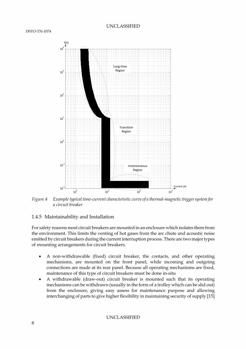
The break/trip time is the delay between when a circuit breaker detects a fault and when it interrupts the current. The break time of a circuit breaker is primarily determined by the current flowing through it, with the break time inversely proportional to load current. The break time can vary enormously from thousands of seconds, for a long-term low-level overload, to milliseconds in a short circuit condition. An important parameter that is often associated with the break time of a circuit breaker is its i2t characteristic rating. This parameter relates the break time as a function of prospective current up to the rated short-circuit breaking capacity of a circuit breaker [1], and allows the break time to be calculated for a given fault current magnitude. Circuit breakers are usually controlled with either a thermal-magnetic trigger system, or an electronics controller. An example of a trip time vs. current characteristic curve of a traditional thermal-magnetic driven circuit breaker is shown in Figure 4. It can be seen that there are three distinct operating regions [14]:
Long-time region - where the current flowing through the circuit breaker is above 100% but below 500% of rated uninterrupted current
Instantaneous region – in this region the circuit breaker is tripped instantaneously by the magnetic latch system with no intentional delay
Transition region - the trip behaviour in this region is not clearly defined, as it is dependent on the operating condition of the circuit
Modern circuit breakers for higher power applications are generally controlled by electronic tripping devices. The break time characteristics of these controllers retain the general shape of the traditional electro-mechanical systems, but their characteristics are usually much more deterministic and precise, as shown in Figure 5. More information about how the traditional thermal-magnetic controller and the modern electronic controller work can be found in Appendix A.3. 1.4.4 Endurance
Like any mechanical system, the number of repetitive duty cycles (opening and closing) that can be performed by an electro-mechanical circuit breaker is limited. IEEE Standard C37.16-2009 [6] provides guidance for the application limitations relating to repetitive duty of low-voltage electro-mechanical dc power circuit breakers. A summary of the related section in this standard is included in Appendix A.4. Limited information is available in the open literature regarding the expected endurance and failure mechanisms of solid state circuit breakers.
UNCLASSIFIED 7
UNCLASSIFIED DSTO-TN-1074
100
101
102
103
10-2
10-1
100
101
102
103
104
Instantaneous Region
Transition Region
Transition Region
Transition Region
Long‐time Region
t(s)
Current (A)
Figure 4 Example typical time-current characteristic curve of a thermal-magnetic trigger system for
a circuit breaker
1.4.5 Maintainability and Installation
For safety reasons most circuit breakers are mounted in an enclosure which isolates them from the environment. This limits the venting of hot gases from the arc chute and acoustic noise emitted by circuit breakers during the current interruption process. There are two major types of mounting arrangements for circuit breakers.
A non-withdrawable (fixed) circuit breaker, the contacts, and other operating mechanisms, are mounted on the front panel, while incoming and outgoing connections are made at its rear panel. Because all operating mechanisms are fixed, maintenance of this type of circuit breakers must be done in-situ
A withdrawable (draw-out) circuit breaker is mounted such that its operating mechanisms can be withdrawn (usually in the form of a trolley which can be slid out) from the enclosure, giving easy assess for maintenance purpose and allowing interchanging of parts to give higher flexibility in maintaining security of supply [15]
UNCLASSIFIED 8

UNCLASSIFIED DSTO-TN-1074
Figure 5 Time-current characteristic curve of a electronic controlled circuit breaker [16]
Most commercial units are available in both fixed and withdrawable alternatives. 1.4.6 Environmental Factors
The operating environment of a circuit breaker can affect its performance and endurance. Three of the main environment factors for a circuit breaker are:
Ambient operating temperature – directly affects the thermal operation limit of the breaker, which affects its current carrying and interruption ability
Air pressure – affects the behaviour of the arc and thermal conductivity of air, leading to altered operating limits
Humidity and pollutant – affect the behaviour of the arc and also can reduce the endurance of the electro-mechanical contact
These issues are further explored in Appendix A.5. 1.5 Key Circuit Breaker Types
While the basic operating principles of all circuit breakers are quite similar, a number of specialist types of technologies have been developed for various operating conditions. In this section a number of important technologies used in circuit breakers will be outlined, and brief discussions will be included about their applicability to low voltage power dc circuit breakers (defined as dc circuit breakers with voltage rating at or below 3200V dc) [6] in submarine application. Discussion in this section is by no means exhaustive, and some concepts and technologies will be examined in greater detail in subsequent sections of this report. 1.5.1 Air Arc Chute Circuit Breaker
An air arc chute circuit breaker uses an electro-mechanical contact to provide the required circuit isolation, while the arc generated during the circuit interruption process helps to
UNCLASSIFIED 9

UNCLASSIFIED DSTO-TN-1074
dissipate stored energy in circuit inductance. In these breakers the arc is forced into the arc chute, where it is stretched and cooled to help dissipate the heat generated by it. After most of the energy is dissipated as heat, the electrical arc extinguishes leaving an open circuit [15, 17]. This technology is widely used in low voltage, high power traction and marine applications [18, 19]. This technology is also used in most low voltage, low power moulded-case circuit breakers [14, 20] commonly found in residential and commercial premises. This technology is commonly used in submarines, and is discussed in greater detail in section 2.2. 1.5.2 Vacuum Circuit Breaker
In a vacuum circuit breaker, the electro-mechanical contact and the arc are enclosed within a vacuum sealed vessel. As the dielectric constant of vacuum is significantly higher than most materials, the vacuum gap of a relatively short distance can achieve sufficiently high dielectric strength for good arc quenching [2]. They are popular in low to medium voltage ac applications, where their compact size, low maintenance, low noise and essentially silent operation are much favoured [15]. However, this technology is not as common in low voltage dc applications. Circuit breakers based on vacuum interrupter are mainly developed by Japanese manufacturers, such as Hitachi which applies this technology for circuit breakers in traction applications [21]. This technology and detail characteristic of vacuum arc will be discussed in greater detail in section 2.3. 1.5.3 Air Blast Circuit Breaker
Similar to air arc chute circuit breakers, air blast circuit breakers also use electric arcs in atmospheric air to aid with current interruption [15]. They cool and extinguish the arc by blowing compressed air through the arc [15], minimizing the need for an arc chute. However, a mechanism to store and generate compressed air is required, and a silencer is often needed to keep the operating noise to an acceptable level [15]. Air blast circuit breaker have been steadily replaced by other technologies [15] and are not actively applied in low voltage dc breakers (no commercial products were found in this domain), hence they will not be reviewed in detail in this report. 1.5.4 SF6 Circuit Breaker
Sulfur hexafluoride (SF6) is a colourless, odourless, non-toxic and non-flammable gas that has a high dielectric strength. When used in a circuit breaker application, this gas is generally kept in a compressed state in an enclosed vessel which surrounds the electro-mechanical contact [15]. Compared to atmospheric air, SF6’s high dielectric strength increases the arc voltage, thus improving the arc quenching properties of the circuit breaker. During the arcing phase, high pressure SF6 is “puffed” through the arc to help extinguish the arc, and chemically decomposes into various components to help cool the arc [15]. While popular in high voltage ac applications, no examples of low voltage dc circuit breakers based on this technology are known. Additionally whilst SF6 is non-toxic and contained in a pressure vessel, it is much heavier than air, therefore it poses risks of suffocation due to displacement of air if a leak develops in an enclosed area. Hence the usefulness of this
UNCLASSIFIED 10

UNCLASSIFIED DSTO-TN-1074
UNCLASSIFIED 11
technology in a submarine application will be limited. This technology will not be further discussed in this report. 1.5.5 Solid State and Hybrid Circuit Breaker
Compared to previously discussed technologies which have been well established since the 1950s to 1970s [15], development of solid state circuit breakers is a relatively recent [22-28] evolution in the field of circuit interruption. Solid state circuit breakers replace the electro-mechanical contact with semiconductor switch/switches to achieve the required open-circuit disconnection. Taking advantage of semiconductor devices with high switching speed and high current carrying capacity developed during the past three decades, modern solid state circuit breakers have an interruption speed of a few to 100s of micro second [23, 27, 28], as compared to milliseconds break time for arc chute based circuit breakers [15]. Because there are no electric arcs within the circuit breaker, external circuit elements are required to dissipate the stored energy in circuit inductance [24, 28]. Interestingly, techniques have also been developed to allow some solid state breakers to limit the fault current before final interruption [28, 29]. Solid state circuit breakers have been applied to both ac [23, 25-27] and dc systems [22, 24]. While the interruption speed of a solid state circuit breaker is much faster than a conventional circuit breaker, one major disadvantage is high on-state losses compared to conventional electro-mechanical circuit breakers [3]. Hybrid circuit breakers use a combination of classical electro-mechanical circuit breakers and semiconductor switches to overcome this problem [30]. In a hybrid circuit breaker current is normally carried through the low loss electro-mechanical contact, and the semiconductor switches are used to reduce or eliminate arcing during circuit interruption [30]. Solid state and hybrid circuit breakers are largely still in the research and development stage. As a result very few commercial products based on these techniques have been reported to date. As an emerging circuit breaker technology, the detailed operating principles, topologies and benefits of solid state and hybrid circuit breakers in a submarine application will be discussed in greater detail in Chapter 3. 1.6 Summary
This chapter outlined the needs and challenges in protecting a submarine power distribution system against faults. Basic operating principles of circuit breakers and how these devices can help to achieve the protection objectives was also discussed. Key performance specifications including current and voltage ratings and how operating environment can affect the performance of a circuit breaker were briefly outlined. The major technologies used in circuit breakers were summarised; it was found that air arc chute, vacuum, solid state and hybrid based systems are dominant technologies in the application of low voltage circuit breaker.
UNCLASSIFIED DSTO-TN-1074
2. Arc Based DC Circuit Breakers
Air arc chute and vacuum based circuit breakers use electro-mechanical contacts to achieve the required circuit isolation, while the electric arcs generated when the contacts open is used to help to dissipate energy stored in circuit inductance. Air arc chute circuit breakers are by far the most dominant circuit breaker technology in low voltage dc power applications, while vacuum circuit breakers offer some unique advantages that may be quite attractive in a submarine application. In air arc chute and vacuum circuit breakers, the behaviour of the electric arc formed during the current interruption process strongly affects the overall performance of these breakers. In order to fully understand the behaviour of these two types of circuit breakers, a basic understanding of electric arcs is necessary. In this chapter, the role of the electric arc in circuit breakers will be explored in detail. A detailed discussion on the structure and working of air arc chute and vacuum based circuit breakers also follows. 2.1 Electric Arc
An electric arc is a cloud of plasma consisting of electrons and ionised atoms. Due to the presence of these charged particles, an electric arc is capable of carrying current. Ionisation of an atom occurs when it gains sufficient energy such that some of its electrons can be disassociated; thereby converting the atom into a charged (positively or negatively) ion. Ionisation can be caused by a number of means; for a circuit breaker thermal ionisation and ionisation by inelastic collisions are of particular interest. These two processes will be discussed in detail here. During the process of thermal ionisation, atoms are heated to a state where they gain sufficient energy for electrons to dissociate. For example if nitrogen gas is heated, at roughly 4,000 K the nitrogen molecule (N2) will begin to dissociate to monatomic nitrogen. At about 5,000 K nitrogen atoms will begin to ionise and form plasma. At a temperature of 20,000 K there is almost no neutral gas left and the plasma is said to be fully ionised [2]. The second type of ionisation is caused by collision between two atomic level particles [2, 15]. There are two types of collision that can occur - elastic and inelastic collisions. Only inelastic collisions lead to ionisation. In an inelastic collision the energy of one particle will be transferred to another, causing a change of state in that particle. There are multiple types of inelastic collision; for this application collisions which cause ionisation are of particular interest. In this type of inelastic collision, the impacting particle has an energy that is equal or greater than the energy required to remove the most weakly bonded electron in an atom, thus ionising the atom. Using ionisation of a nitrogen atom as an example, equation (2.1) demonstrates a possible process for ionisation by inelastic collision. 2e N e N (2.1) Both of these types of ionisation processes are constantly occurring during the burning of an arc.
UNCLASSIFIED 12

UNCLASSIFIED DSTO-TN-1074
2.1.1 Formation of Electric Arc in Air Due to Opening of an Electrical Contact
As an electrical contact opens, the holding force of the contact decreases, and the contact resistance increases as modelled in equation (2.2) [2]. This causes the resistive loss to increase, heating up the contact point.
2c
HR
F
(2.2)
where Rc is the contact resistance, H is the material hardness, ρ is the resistivity, and F is the holding force. Therefore when a circuit breaker with sufficient operating current and voltage opens its electro-mechanical contact, a large amount of heat can be generated. The heat generated at the metallic contact can melt the surfaces of the parting contact, and causes bridge of molten metal to form between the parting contact. As the electrical contact continues to open, this bridge is lengthened and stretched until it eventually ruptures, releasing hot metal vapour in the contact gap. Figure 6 [2] demonstrates how this process progresses as a electro-mechanical contact opens. When an arc is first established metal atoms from the hot metal vapour are ionised in preference to the gas molecules in air due to their lower ionisation energy. These atoms can be ionised by two means - thermal ionisation and ionisation by inelastic collision. The ionised metal atoms form the initial electric arc as the electro-mechanical contact opens, and lead to ionisation of gas molecules in the contact gap which require higher energy. Once the gas between the contact’s surfaces are ionised, the electric arc is fully established. 2.1.2 Structure of Electric Arc in Air
An electric arc in air can be divided into three distinct regions, the arc column, the cathode region and the anode region. A schematic of an electric arc constricted between two contact surfaces is shown in Figure 7 [2]. The arc column consists of the plasma made up of ionised gases and metal vapours. The density of electrons and ions are equal, and the column is neutral in charge. The presence of
T = Tm
Bridge Forms
Tm < T < Tbl
Stable Bridge
Bridge rupture.Arc forms between
parting surfaces Figure 6 Formation and rapture of molten metal bridge [2], T = temperature, Tm = melting
temperature of metallic contact, Tbl = boiling temperature of material in contact
UNCLASSIFIED 13

UNCLASSIFIED DSTO-TN-1074
Electrons
Current
Arc Column
Cathode Anode
Cathode fall Anode fall
Ua
Ucol
Uc
Arc Voltage
Figure 7 Electric arc constricted at the contacts in air and the corresponding voltage
distribution [2]
these charged particles allows the column to carry electric current. The temperature in this region can range from 6,000 K to 20,000 K depending on the current flowing through the arc. While both electrons and ions are present in this region, current is carried mostly by electrons. This is primarily due to the electron’s lighter weight compared to the ions present; hence they can travel at a much higher speed under the same applied field. The cathode contact provides a source of electrons which allows the arc to continue to burn. Once this source ceases the arc is terminated. Electron emission can be caused by a number of methods. One such method is thermal emission, where electrons can be emitted from a metal when they gain sufficient energy to overcome the binding potential to escape. Thermal emission is generally confined to high melting point metals such as tungsten, because the high temperature required for this process will melt most metal before electrons are emitted. For most other metals, electrons are emitted via two methods. The first method is called thermally enhanced field emission, where electrons in the metal atoms gain sufficient kinetic energy from the heat and the strong electric field presence to overcome the binding energy and escape. The second method is called ion bombardment, where ionic atoms collide inelastically with metal atoms to trigger emission of electrons.
UNCLASSIFIED 14

UNCLASSIFIED DSTO-TN-1074
A voltage drop of roughly 15 V in magnitude is observed in the cathode region [2, 17], though the exact magnitude of the drop depends on the magnitude of the current flow [15]. This voltage drop is commonly called cathode fall. The anode region acts as a collector of electrons, and similar to the cathode region it also causes a voltage drop. The size of voltage drop in this region depends on the magnitude of current flowing [15, 17], but 15-20V drop is typical in this region [2]. This voltage drop is commonly called anode fall. 2.1.3 Application of Electric Arcs in DC Circuit Breakers
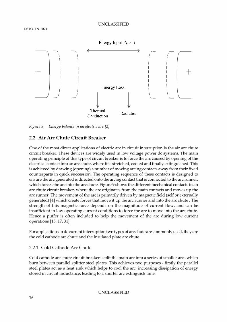
In a dc circuit breaker electric arcs provide two functions. Firstly they provide a mechanism to slowly increase the voltage across the opening circuit breaker during current interruption. This is achieved by stretching and lengthening the arc column, thereby increasing its resistance and the voltage drop across the circuit breaker [2, 4, 15]. This slow increase limits the rate of change of current in the circuit, which in turn limits the voltage overshoot caused by the sudden change in rate of current flow in the circuit inductance. This effect is clearly demonstrated in equation (1.2), where the relative size of VB against (Vdc – RI) directly controls the rate of change of circuit current. The second function of an electric arc is to dissipate energy stored in circuit inductance. As an arc burns, the amount of energy that enters the arc must also be balanced by energy that it dissipates/loses. While energy into the arc is the product of arc voltage and current, and energy out is the sum of thermal conduction and radiation (both visible and high frequency radiation) losses. Once energy dissipated exceeds energy in, the arc will extinguish [4]. Thermal conduction is one way the arc loses energy. During the burning of an arc, a temperature of roughly 5,000-20,000 K is generated by the arc to maintain the process of thermal ionisation. This high temperature leads to substantial loss of energy through the process of thermal conduction. Visible light of an arc is also a source of energy loss. This is partly caused by recombination of charged atomic particles at the arc column, which revert the ionisation energy of the atom to kinetic energy and visible light and higher frequency radiations. The energy balance of an electric arc can be summarised in Figure 8 and equation (2.3) [2].
2 1col r
d dTE r
r dr dr
P
(2.3)
where r is the arc radius (radius of arc column), к the thermal conductivity, Pr is the radiation loss, σ the electrical conductivity and Ecol is the column’s electric field. The loss of energy through thermal conduction and radiation allows a gradual decrease of energy stored in the circuit inductance, and helps to limit the voltage overshoot caused by the sudden change of current flow in the circuit.
UNCLASSIFIED 15
UNCLASSIFIED DSTO-TN-1074
Figure 8 Energy balance in an electric arc [2]
2.2 Air Arc Chute Circuit Breaker
One of the most direct applications of electric arc in circuit interruption is the air arc chute circuit breaker. These devices are widely used in low voltage power dc systems. The main operating principle of this type of circuit breaker is to force the arc caused by opening of the electrical contact into an arc chute, where it is stretched, cooled and finally extinguished. This is achieved by drawing (opening) a number of moving arcing contacts away from their fixed counterparts in quick succession. The operating sequence of these contacts is designed to ensure the arc generated is directed onto the arcing contact that is connected to the arc runner, which forces the arc into the arc chute. Figure 9 shows the different mechanical contacts in an arc chute circuit breaker, where the arc originates from the main contacts and moves up the arc runner. The movement of the arc is primarily driven by magnetic field (self or externally generated) [4] which create forces that move it up the arc runner and into the arc chute . The strength of this magnetic force depends on the magnitude of current flow, and can be insufficient in low operating current conditions to force the arc to move into the arc chute. Hence a puffer is often included to help the movement of the arc during low current operations [15, 17, 31]. For applications in dc current interruption two types of arc chute are commonly used, they are the cold cathode arc chute and the insulated plate arc chute. 2.2.1 Cold Cathode Arc Chute
Cold cathode arc chute circuit breakers split the main arc into a series of smaller arcs which burn between parallel splitter steel plates. This achieves two purposes - firstly the parallel steel plates act as a heat sink which helps to cool the arc, increasing dissipation of energy stored in circuit inductance, leading to a shorter arc extinguish time.
UNCLASSIFIED 16

UNCLASSIFIED DSTO-TN-1074
Figure 9 Structure of arcing contact of a arc chute circuit breaker [15], © The IET
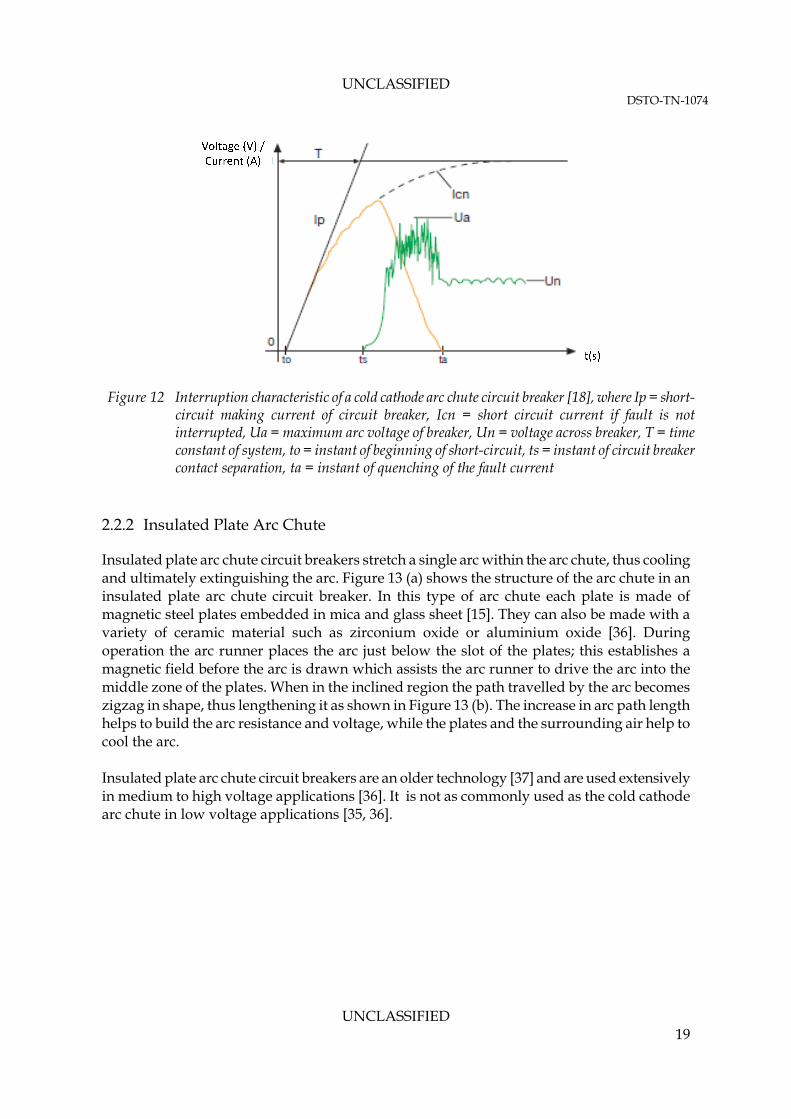
The second purpose is to increase the amount of total voltage drop across the circuit breaker (VB in Figure 1) by increasing the number of cathode and anode falls. Each small arc formed has the same structure as shown in Figure 7; hence each arc has its own cathode and anode fall regions. These two regions contribute to a significant portion of the total voltage drop in an arc and can be as much as 30-40V in magnitude. Therefore as the number of small arcs increases within the cold cathode arc chute, the number of fall regions and total voltage drop across the circuit breaker increase accordingly. Figure 10 shows the overall structure of this type of circuit breaker. Figure 11(a) shows the final arcing position of a cold cathode arc chute, including where the moving arcing contact finally rests and how a series of small arcs are formed within the arc chute. Figure 11(b) shows a diagram of a steel plate used in a cold cathode arc chute, where it can be seen that the magnetic field produced by the arc column forces the arc into the arc chute’s steel plate. Once an arc is forced into the steel plate, it can travel up the steel plate until it reaches the top, where it is stopped by the insulated coating from exiting the confine of the chute. Figure 12 [18] shows the overall interruption characteristics of a cold cathode arc chute dc circuit breaker. It shows the voltage and current waveform as a circuit breaker moves into different stages of operation until the arc extinguishes and the electrical contact becomes an open circuit. It can also be seen that the arc does not give a constant voltage as it burns, and shows some signs of volatility in voltage, due to the non-linear nature of the arcing process. Air arc chute circuit breakers are used in a wide range of applications from low power moulded case circuit breakers to power circuit breakers, and are presently the most common technology used in low voltage dc current interruption applications [15, 20, 31-36].
UNCLASSIFIED 17

UNCLASSIFIED DSTO-TN-1074
Figure 10 Structure of a dc circuit breaker with cold cathode arc chute [15], © The IET
(a) (b)
Figure 11 (a) Cold cathode arc chute and arc runner, (b) Cold cathode arc chute plate [15], © The IET
UNCLASSIFIED 18
UNCLASSIFIED DSTO-TN-1074
Figure 12 Interruption characteristic of a cold cathode arc chute circuit breaker [18], where Ip = short-circuit making current of circuit breaker, Icn = short circuit current if fault is not interrupted, Ua = maximum arc voltage of breaker, Un = voltage across breaker, T = time constant of system, to = instant of beginning of short-circuit, ts = instant of circuit breaker contact separation, ta = instant of quenching of the fault current
2.2.2 Insulated Plate Arc Chute
Insulated plate arc chute circuit breakers stretch a single arc within the arc chute, thus cooling and ultimately extinguishing the arc. Figure 13 (a) shows the structure of the arc chute in an insulated plate arc chute circuit breaker. In this type of arc chute each plate is made of magnetic steel plates embedded in mica and glass sheet [15]. They can also be made with a variety of ceramic material such as zirconium oxide or aluminium oxide [36]. During operation the arc runner places the arc just below the slot of the plates; this establishes a magnetic field before the arc is drawn which assists the arc runner to drive the arc into the middle zone of the plates. When in the inclined region the path travelled by the arc becomes zigzag in shape, thus lengthening it as shown in Figure 13 (b). The increase in arc path length helps to build the arc resistance and voltage, while the plates and the surrounding air help to cool the arc. Insulated plate arc chute circuit breakers are an older technology [37] and are used extensively in medium to high voltage applications [36]. It is not as commonly used as the cold cathode arc chute in low voltage applications [35, 36].
UNCLASSIFIED 19

UNCLASSIFIED DSTO-TN-1074
Figure 13 Insulated plate arc chute circuit breaker [15], © The IET
2.2.3 Commercial Air Arc chute Circuit Breaker for Submarine Application
Air arc chute circuit breakers are very popular in low voltage dc power applications, especially for traction and rail applications. These circuit breakers are also widely used in naval [22] applications including submarines [19]. Important specifications of a number of selected commercial low voltage dc circuit breakers are summarised in Table 1.
Figure 14 shows a photo of a commercially available air arc chute circuit breaker, the ABB Emax dc circuit breaker [18]. Air arc chute circuit breakers are currently used in Collins class submarines operated by the RAN. The rating and physical characteristics of the installed circuit breakers are similar to those listed in Table 1.
UNCLASSIFIED 20

UNCLASSIFIED DSTO-TN-1074
Table 1 Summary of commercial air arc chute circuit breakers
Specifications Products Iu (kA) Icu (kA) Ue (volts) Break time (ms) Weight (kg)
ABB SAC Emax dc Circuit Breakers [18]
0.8 – 5 35 – 100 500 - 1000 60 50 – 240
GE Energy Gerapid [32]
2.6 – 8 35 – 71 2,000 – 4,000
Unknown 120 – 220
Secheron High Speed dc CB - UR series [39]
2.6 – 4.6 31.5 – 100
900 – 3,600 15 – 30 77 – 154
Secheron High Speed dc CB, HPB series [40]
4.5 – 6 31.5 - 100 900 – 1,800 8 – 20 108 – 137
Siemens Sitras DSG [41]
2.6 – 8 40 – 125 900 – 3,600 Unknown 190 – 230
Schneider Electric PIX DC [42]
2.4 – 6 80 – 125 900 – 1,800 Unknown N/A
Figure 14: ABB EMax DC circuit breaker [18]
Due to the limited voltage withstand ability of a single contact, it is common for a number of contacts (poles) to be connected in series to achieve the required rated operational voltage of a circuit breaker. This technique is used in low voltage power circuit breakers with arc chute, with some commercial products using up to 4 poles connected in series to achieve the required voltage rating of 1000 V dc [18, 38]. Figure 15 shows several different pole configurations and corresponding bus bar structures used in commercial circuit breakers rated between 500-1000 V dc. Air arc chute circuit breakers are typically closed by solenoids and motors powered by an external supply [15, 18, 43]. Once closed, contacts are generally held by springs [15]. During opening, these springs are released to allow rapid opening of the contact during current interruption. Because of the electrical power required to operate both controller and operating mechanism, during the loss of external power these circuit breakers may become inoperable. While not a standard feature in most commercial circuit breakers, mechanisms to manually close and open a circuit breaker [18, 32, 44] can be installed, allowing manual operation
UNCLASSIFIED 21

UNCLASSIFIED DSTO-TN-1074
Figure 15 Pole and bus bar configuration of a series of commercial dc circuit breakers at 500-1000 V [45]
during a power blackout, and should be considered in submarine applications where damage control is needed. In a submarine application where compressed air is readily available, pneumatic operating mechanisms may be used. Pneumatic drive circuit breakers have the advantage that they can remain operable during an electrical blackout event. In general as the rated voltage increases the current breaking capacity of a circuit breaker decreases. This is because the energy of an electric arc increases as operating voltage increases, therefore decreases in current rating is required to limit the stress on the electrical contract. The size and weight of circuit breakers can vary significantly depending on the voltage and current ratings. Generally as voltage and current ratings of a circuit breaker increase, the weight increases proportionally. This is mainly due to the increased amount of bus capacity needed to cope with the load. For low voltage dc power circuit breakers, low continuous current rating commercial units can weigh between 50-60 kg, while higher continuous current rating units can weigh more than 200 kg [18, 32, 38, 44]. With rated breaking capacity of up to 100 kA, commercially available air arc chute circuit breakers should be sufficient for most existing flooded lead-acid submarine power systems. However care must be taken to fully consider the following:
Sufficient clearance must be provided such that exhaust from an arc chute can escape safely and in an unimpeded manner,
De-rating might be required due to variation in ambient temperature and air pressure during operation, and
It remains unclear if the pitch and roll of a submarine can affect the movement of the arc, and therefore the proper operation of typical commercial circuit breakers.
UNCLASSIFIED 22

UNCLASSIFIED DSTO-TN-1074
Additionally factors such as increased use of power electronic converters and the potential introduction of advanced battery systems as discussed in section 1.3 make it difficult to predict the magnitude of potential fault currents in a future submarine. This suggests more detailed modelling of the power systems used in future submarines is needed before further assessment of the suitability of current technologies can be made. Recommendation 1: DSTO recommends that detailed fault current studies be conducted to determine whether existing circuit breaker technologies have sufficient fault current breaking ability to meet the requirements of a future submarine. 2.3 Vacuum Circuit Breaker
A vacuum circuit breaker encloses its electro-mechanical contacts within a vacuum sealed container. This type of circuit breaker relies on the high dielectric constant of vacuum, which allows higher voltage arcs to develop over a small gap distance giving good arc quenching capability. Compared to gas-based circuit breakers (air blast, air arc chute and SF6), vacuum circuit breakers offer the following advantages [15]:
Entirely self contained, requires no supplies of gases or liquid Emits no flame or gas Requires no maintenance Can be used in any orientation Not flammable Very high commutating ability and needs no capacitors or resistors to interrupt short
line faults Relatively small energy is required to operate them Silent in operation
This type of circuit breaker is widely used in medium voltage ac distribution grids (up to roughly 40 kV) [2, 15, 31]. While not as common, they are also used in some low voltage dc power applications [21]. 2.3.1 Arc in Vacuum
In order to understand the behaviour and characteristics of a vacuum circuit breaker, the behaviour of an arc in vacuum, which is somewhat different from an arc in gases, must first be understood. Electric arcs are plasmas consisting of a mixture of electrically charged ions and electrons. An arc in vacuum is unique because the medium where it burns does not contain any materials which can be readily ionised (e.g. gases); hence the source of electrons and ions must be supplied by the electrodes (electro-mechanical contact). In general, electrons can be liberated from a metallic material by two methods – (1) by providing them with sufficient kinetic energy to surmount the potential barrier of the metal, (2) by reducing the height of and/or thinning the barrier so that electrons can penetrate it and escape (e.g. apply strong field generated by high electrical potential) [2]. In a vacuum circuit breaker, a strong electric field helps lower the potential barrier for electrons to escape at a reduced temperature from the cathode.
UNCLASSIFIED 23

UNCLASSIFIED DSTO-TN-1074
In a vacuum arc, charged ions required to sustain the plasma are provided by ionisation of metal vapours from the cathode at selective sites called cathode spots. At these spots metallic materials from the surface are evaporated and injected into the arc column. These sites are also areas where intense ionisations of metallic atoms take place. As current in the arc further increases, molten metal bridges can rupture as the contact continues to open, ejecting hot metal vapours into the contact gap [2, 46], providing further sources of materials. As a result, a vacuum arc can burn in two modes. At low current the arc burns in a diffuse mode, where a number of small independent arcs, each with a diverging arc plasma column burn in parallel [15]. These arcs are spread across the surface of the cathode. The small thermal time constant of about 1μs allows the temperature of these arcs to change rapidly. This allows vacuum arcs burning in diffused mode to have a high current interruption capability, as heat can be rapidly dissipated to extinguish the arcs. As the current of the arc increases and the metal bridge formed during the opening of the contact ruptures, the arc will turn into a constricted [15] or columnar [2, 46] form. During the transition between the two modes, the small arcs that burn in the initial diffused mode are forced by electric fields developed during the burning of the arc to join into a large constricted arc. A constricted arc can generate intense heat which can melt large areas of the contact surface, leaving a pool of molten metals at the arcing site [2]. As the thermal time constant for these strongly vaporising pools of metal is long [2] this type of arc has a comparatively high thermal time constant of a few hundreds of microseconds to a few milliseconds [15]. Because of the long thermal time constant the current interruption capacity of a constricted arc is limited. However, it is possible for an arc burning in constricted mode to revert to diffuse mode once the current through the arc decreases, and in some breakers this property is exploited to help minimise the arcing time. As a vacuum arc extinguishes, the vapour density falls to essentially zero, leaving a good vacuum [15]. A vacuum breaker can continue to function until the surface of the electro-mechanical contact becomes so worn by the arcing process that it can no longer conduct and break properly. While the formation and behaviour of a vacuum arc is somewhat different from that of an arc in air, the functions of a vacuum arc in a circuit breaker application remain identical as described in section 2.1.3, namely to provide a controlled rate of increase in circuit breaker voltage, and to dissipate energy stored in circuit inductance. Vacuum circuit breakers can, in general, interrupt faster than an air arc chute type circuit breaker as the travel distance for electrodes is shorter and the dielectric constants of the arcing medium are higher [15].
UNCLASSIFIED 24

UNCLASSIFIED DSTO-TN-1074
2.3.2 Structure of a Vacuum Circuit Breaker
Figure 16 shows the structure of a vacuum interrupter, where it can be seen that the electro-mechanical contact is contained in a glass or a ceramic vessel which is sealed in high vacuum at time of manufacture (typically lower than 10-5 mbar after fabrication). This seal is required to last over the life time of the circuit interrupter [2]. Typical contact stroke distance lie at a few millimetre, with opening speed of 1 metre per second or lower [2]. Electro-mechanical contacts of a vacuum interrupt are designed to manipulate the magnetic fields generated by the arc such that the optimal current interruption characteristic can be achieved. As discussed in section 2.3.1, in general the current interruption capacity of a diffused arc is better than that of a constricted arc due to its low thermal time constant. However, a constricted arc inevitably develops as current flow increases. There are two methods to deal with this problem. One solution is to force a constricted arc to rotate which helps distribute the heat of the arc evenly across the whole contact area [46], thus reducing the cooling time constant of the metal vapours. This can be achieved by applying a radial magnetic field; electrical contacts which are designed to apply this type of magnetic field are shown in Figure 17 (a) and (b). Another solution is to force the arcs to stay in a defused state even at a higher current - this can be achieved by applying an axial magnetic field at the electrical contact [2, 46]. Figure 17 (c) shows an electrical contact designed for this application. Figure 18 shows the structure of a medium-voltage vacuum breaker, and shows how the vacuum interrupter is fitted into the overall structure.
Figure 16 Operating mechanisms of a vacuum interrupter[47]
UNCLASSIFIED 25

UNCLASSIFIED DSTO-TN-1074
The lack of a natural current zero point (e.g. current zero crossing in an ac circuit) in dc circuit breaking means it is often difficult to force a vacuum arc into a diffuse mode where it is easier to extinguish. One approach is to artificially generate such a point. An artificial current zero point can be generated by imposing a high frequency counter-current during the current interruption, forcing the current to zero. Figure 19 shows how this can be achieved with a series inductor, capacitor and a switch that are connected in parallel to the main vacuum circuit breaker. During normal operation the vacuum circuit breaker CBm is closed, the switch CBc is opened, and the high frequency current source capacitor Cc is charged with a voltage that opposes the polarity of the main source voltage U. During current interruption, CBc is
Figure 17 Vacuum contact structure for different magnetic fields: (a) cup contacts for radial field; (b) spiral contacts for radial field; (c) third of a winding for axial field [2]
Figure 18 Medium-voltage vacuum circuit-breaker, 1, breaker mechanism housing; 1.1, front panel, removable; 12 insulating material pole tube; 13, upper breaker terminal; 14, lower breaker terminal; 15, vacuum interrupter; 16, roller contact; 17, contact pressure spring; 18, insulated coupling rod; 19, opening spring; 20, shift lever pair [2]
UNCLASSIFIED 26

UNCLASSIFIED DSTO-TN-1074
Figure 19 DC circuit with vacuum breaker and high frequency current source, where U is the circuit dc voltage source, R and L are load resistance and inductance, Cc and Lc are the capacitance and inductance of high frequency current source, and CBc and CBm are the
high frequency current source and main circuit breaker [50]
closed causing a high frequency current ic to flow in the opposite direction to the main current im. This helps to drive the current in CBm to zero and extinguish the arc. Variations of this strategy are often used in dc vacuum circuit breakers [48-50]. While popular in medium voltage ac applications, low voltage dc applications for vacuum circuit breakers are limited. The only commercially available low voltage dc circuit breakers are those manufactured by Hitachi [21] and Toshiba [49, 51], with a voltage range from 750 V to 1800 V, continuous current rating of 3,000 A to 4,000 A and rated breaking capacity of 100 kA. 2.4 Sensitivity to Shock and Vibration
Performance of electro-mechanical contacts and associated mechanisms used in air arc chute and vacuum circuit breakers can be adversely affected by shock and vibration. This includes the risk of unexpected trip or opening of a breaker which can cause potentially dangerous and unexpected operating conditions. Most commercial circuit breakers can withstand some level of shock and vibration. For example the GErapid series of circuit breakers from can withstand “maximum vibration of 0.5g per 30sec in vertical and horizontal directions” [32]. Limited documentation in the form of data sheets and operating manuals for circuit breakers used in the 1950s by the U.S. Navy [52, 53] have indicated that mechanical systems have been designed to avoid accidental tripping and closing in air arc chute circuit breakers due to shock. However, their equivalents in modern circuit breakers are not well documented.
UNCLASSIFIED 27

UNCLASSIFIED DSTO-TN-1074
UNCLASSIFIED 28
2.5 Summary
Electric arcs are commonly used in circuit breakers to provide a controlled and slowed voltage rise across the opening electrical contact to prevent sudden changes of current flow in the circuit, and to allow dissipation of energy stored in circuit inductance. In this chapter the characteristics of electric arcs and how they have been applied in applications for current interruption have been detailed. Air arc chute circuit breakers are well developed and mature technology for dc current interruption. They have been applied to high power traction [39, 44] and submarine [19] applications. Therefore this technology presents a relatively low risk solution for this application. The self contained nature and long service life of a vacuum circuit breaker are very attractive for submarine applications. However research [3, 48-50, 54], development and commercialisation [21, 54] of this technology for applications in low voltage circuit breakers are somewhat limited. This might restrict their applicability due to difficulty in procurement. Circuit breakers discussed in this chapter are potentially vulnerable to the effects of shock and vibration. However, limited information /data is freely available. Careful considerations and further research is therefore required to ensure the shock and vibration withstand capacity of these circuit breakers are adequate for their expected operating environment. Both air arc chute circuit breakers and, to a lesser extent, vacuum circuit breakers are well established solutions to the problem of current interruption in low voltage dc circuits (i.e. below 3,200V dc). This is especially true for air arc chute circuit breakers which are currently used in Collins class submarines operated by the RAN. However it remains unclear as to whether the rating of available products are adequate for the possible increases in fault current in a future submarine with advanced battery systems and increases power electronic converters. Further research and development is needed to model the severity of faults in a future submarine with advanced battery systems and how these can affect the rest of the system.
UNCLASSIFIED DSTO-TN-1074
3. Solid State and Hybrid Circuit Breakers
In a solid state circuit breaker, the role of electro-mechanical contacts is replaced by power semiconductor devices/switches. These devices have well defined on-state loss profile, and are able block a certain amount of voltage when turned off. Since they have a much faster switching speed compared to the traditional electro-mechanical contact, significant improvements in the fault interruption speed can be achieved [27]. Furthermore as there is no electric arc created by electro-mechanical contacts, these circuit breakers can operate in silence, and do not emit gas or flame. These characteristics make solid state circuit breakers quite attractive in a submarine application. However, disadvantages of these circuit breakers include increased sensitivity to electromagnetic interference (EMI), higher on-state losses, and lack of physical/galvanical isolation in the opened state (devices turned off). Hybrid circuit breakers combine classical electro-mechanical contacts with semiconductor devices. This overcomes the high on-state losses in a solid state circuit breaker, while also minimising the arcing and resulting mechanical wear in the electro-mechanical contacts. However structure of the hybrid circuit breakers is more complex. The behaviour of semiconductor devices must be understood before the behaviour of these two solid state circuit breakers is discussed. Therefore this chapter first briefly discusses the semiconductor devices used in these circuit breakers, then summarises major circuit topologies used in dc current interruption applications. Issues and future trends will also be examined. Lastly, the applicable of this type of circuit breaker to a submarine application will be reviewed. 3.1 Power Semiconductor Devices
Power semiconductor devices are the key components in both solid state and hybrid circuit breakers. A semiconductor device is an electronic component which exploits the electronic properties of semiconductor materials. Key materials in modern semiconductor devices include silicon, germanium, silicon carbide and gallium arsenide. Devices with controllable resistance can be formed by combining layers of semiconductor materials doped with different impurities. This effect allows a semiconductor device to simulate the behaviour of a mechanical switch. When fully turned “on”, it allows current to pass through with little losses (simulating a closed mechanical switch), but when turned “off” the device’s high resistance blocks the flow of current (simulating an opened mechanical switch). Semiconductor devices can also be put into the linear operating region where their conductivity, rate of current flow and on-state voltage depend on the magnitude of gate signal applied. This state is actively exploited in electronic components such as an operational amplifier, but is rarely used in power semiconductor devices operating in a switching environment. In these systems semiconductor devices are driven “hard” on and off to minimise operating losses and maximise operating speed. In summary an ideal switching power semiconductor device should have the follow characteristics:
When turned off, it should be able to block infinite voltage in forward and reverse direction, with zero current flow
UNCLASSIFIED 29
UNCLASSIFIED DSTO-TN-1074
When turned on it should be able to conduct arbitrarily large current with no energy loss
Instantaneously transit between operating states Require zero power to change between states
Inevitably these ideal characteristics can never be achieved in any practical devices. Practical devices are limited in their blocking voltage, operating current, switching speed, and suffer from other non-ideal characteristics. As a result, these devices incur two types of energy loss during operation. Switching losses are incurred at each switching transition, and during steady state operation these devices also suffer from on-state losses. These energy losses are dissipated as heat and do not contribute to useful work. While the ideal instantaneous switching of state is unattainable in practical semiconductor devices, the switching speed of even the slowest semiconductor device is still substantially faster than that of any electro-mechanical switch. This allows solid state circuit breakers to have very high interruption speeds. A discussion of key operating limits, typical switching profile and loss mechanisms of semiconductor devices is included in Appendix B. Development in semiconductor technologies has advanced considerably in the past few decades, and a large array of devices have been developed [55, 56]. However, only a limited number of semiconductor devices are commonly used in solid state circuit breakers. These devices include:
Diode Thyristor Gate Turn-Off Thyristor (GTO) Integrated Gate-Commutate Thyristor (IGCT) Insulated Gate Bipolar Transistor (IGBT)
Each of these devices has different characteristics which make them desirable in specific applications. However, due to their superior switching characteristics, on-state losses and controllability, IGCTs and IGBTs are the preferred modern devices for solid state dc circuit breakers. At lower voltages IGBT devices can offer better switching characteristics at roughly the same level of on-state losses when compared to available IGCT devices. However, as blocking voltage of the system increases (beyond roughly 1,700 V), the on-state losses and current rating of existing IGCT devices become better than those of commercially available IGBTs [57, 58]. In Appendix C important operating characteristics of these devices are discussed. 3.2 Topologies for Solid State Circuit Breakers
Solid state circuit breakers rely solely on the solid state switch to carry nominal load and to interrupt current. Because the electric arc is eliminated, another mechanism is needed to dissipate the stored energy in circuit inductance. This is often achieved via parallel connected metal-oxide varistor (MOV) [59]. A MOV has a non-linear voltage/current characteristic. Its resistance remains high (effectively acting as an open circuit) until voltage across it reaches a
UNCLASSIFIED 30
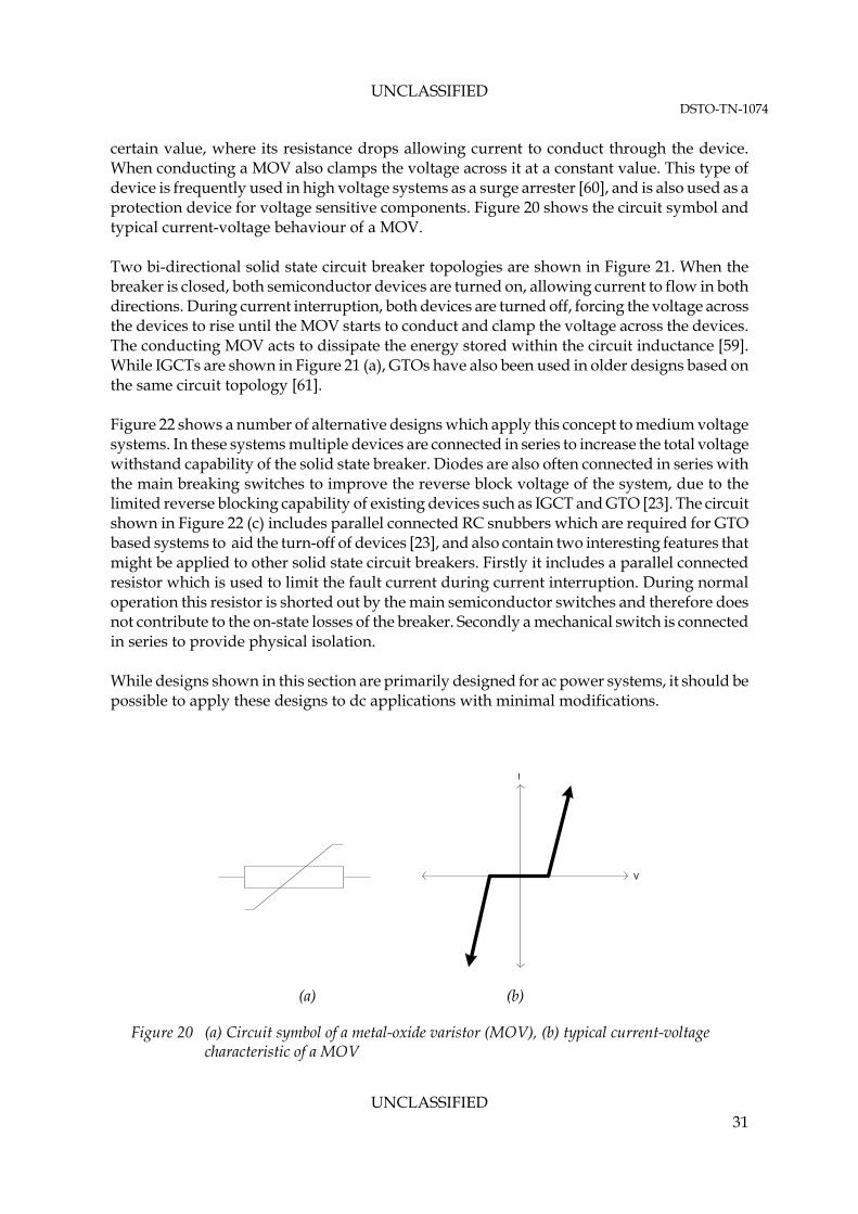
UNCLASSIFIED DSTO-TN-1074
certain value, where its resistance drops allowing current to conduct through the device. When conducting a MOV also clamps the voltage across it at a constant value. This type of device is frequently used in high voltage systems as a surge arrester [60], and is also used as a protection device for voltage sensitive components. Figure 20 shows the circuit symbol and typical current-voltage behaviour of a MOV. Two bi-directional solid state circuit breaker topologies are shown in Figure 21. When the breaker is closed, both semiconductor devices are turned on, allowing current to flow in both directions. During current interruption, both devices are turned off, forcing the voltage across the devices to rise until the MOV starts to conduct and clamp the voltage across the devices. The conducting MOV acts to dissipate the energy stored within the circuit inductance [59]. While IGCTs are shown in Figure 21 (a), GTOs have also been used in older designs based on the same circuit topology [61]. Figure 22 shows a number of alternative designs which apply this concept to medium voltage systems. In these systems multiple devices are connected in series to increase the total voltage withstand capability of the solid state breaker. Diodes are also often connected in series with the main breaking switches to improve the reverse block voltage of the system, due to the limited reverse blocking capability of existing devices such as IGCT and GTO [23]. The circuit shown in Figure 22 (c) includes parallel connected RC snubbers which are required for GTO based systems to aid the turn-off of devices [23], and also contain two interesting features that might be applied to other solid state circuit breakers. Firstly it includes a parallel connected resistor which is used to limit the fault current during current interruption. During normal operation this resistor is shorted out by the main semiconductor switches and therefore does not contribute to the on-state losses of the breaker. Secondly a mechanical switch is connected in series to provide physical isolation. While designs shown in this section are primarily designed for ac power systems, it should be possible to apply these designs to dc applications with minimal modifications.
V
I
(a) (b)
Figure 20 (a) Circuit symbol of a metal-oxide varistor (MOV), (b) typical current-voltage characteristic of a MOV
UNCLASSIFIED 31

UNCLASSIFIED DSTO-TN-1074
To eliminate the MOV from solid state circuit breaker Sato et al. [63] have suggested lengthening the turn-off period of main semiconductor devices and effectively operating the devices in linear mode for an extended period of time during the turn-off process. This enables the device to be used to dissipate the stored energy in circuit inductance and hence limits the overall voltage spike. However, this design is only possible with devices that can tolerate a significantly higher operating temperature. Therefore this type of system remains
(a) (b)
Figure 21 (a) IGCT based simple bi-directional solid state circuit breaker [24], (b) IGBT based simple bi-directional solid state circuit breaker [27]
(a) (b)
(c)
Figure 22 (a) IGCT based medium voltage bi-directional solid state circuit breaker [23], (b) IGCT based medium voltage bi-directional solid state circuit breaker [23], (c) GTO based bi-directional solid state circuit breaker [62]
UNCLASSIFIED 32

UNCLASSIFIED DSTO-TN-1074
largely experimental due to lack of appropriate semiconductor devices for this purpose. While the controllability and switching speed of thyristors are limited, their available current and voltage ratings are significantly higher than other devices, making thyristors an attractive solution in high power applications. However, a thyristor will only turn off when current flowing through it drops below the holding current. While the current will naturally zero in an ac circuit, there is no such current zero point in a dc circuit, making it difficult to turn off a thyristor. Hence when thyristors are used in a solid state dc circuit breaker, additional circuit elements must be included to force the devices’ current to zero [25, 64, 65] for commutation. Figure 23 shows a uni-directional thyristor based circuit breaker which uses an inductive and capacitive resonant circuit to produce the artificial zero current point. In this circuit Rs, Ls, RL and LL are source resistance, source inductance, load resistance, and load inductance, respectively. T1 is the main thyristor which conducts current when the breaker is closed. At the start of current interruption T2 is closed, causing the pre-charged capacitor C1 to discharge and oscillates with the inductor L1. This forces a current that opposes the fault current to flow in T1, which creates an artificial current zero point in T1 and enables T1 to be turned off. RC, DC, the transformer T and ac source form a charging circuit which charges the capacitor C1 when the circuit breaker is closed. Finally diode DF provides an alternative current path for current flow if a reverse fault current is somehow induced to prevent damages to the solid state circuit breaker. With correct tuning this resonant circuit should be able to rapidly discharge allowing the main thyristor to turn off. While solid state circuit breakers can achieve substantially faster interruption speed compared to conventional electro-mechanical based circuit breakers, one major drawback of solid state
Fault
Figure 23 Solid state circuit breaker with capacitor aided turn-off [65]
UNCLASSIFIED 33

UNCLASSIFIED DSTO-TN-1074
breakers is their high on-state losses. With contact resistance as small as a few micro-ohms [22], electro-mechanical contacts in classical circuit breakers introduce negligible on-state losses. In contrast, most solid state devices introduce a voltage drop of at least two volts, therefore as large current flow through the breaker, the on-state losses of a solid state circuit breaker can be significantly higher than those of a classical circuit breaker. The increased energy loss also leads to increased requirements for cooling. Traditionally large metallic heatsinks are used to passively cool power semiconductor devices, however, they can contribute to substantial portions of the systems’ overall size and weight. While the installation of active cooling systems such as force air (fan) or liquid cooling might help to reduce the size and weight of the overall system, they introduce additional complexities such as increased acoustic signature, energy losses and maintenance issues. 3.3 Hybrid Circuit Breaker
A hybrid circuit breaker uses a combination of classical electro-mechanical contacts and solid state semiconductor devices in a configuration which minimises the on-state losses of the system, while maintaining a high interruption speed. This is achieved by ensuring current flows through the electro-mechanical contacts when the circuit breaker is closed, thus minimising the on-state losses. When current interruption occurs, the system is configured to use the solid state switches to eliminate or minimise arcing in the electro-mechanical contact, thus allowing the contact to open quickly, substantially reducing wear due to arcing [3]. Figure 24 shows three topologies for bi-directional hybrid circuit breakers. It can be seen that besides the turn-off snubber that is needed for the GTO based system, the general structure of these circuit breakers remains similar. The turn-off snubber suppresses (snub) voltage spikes during the turn-off of a transistor, as these voltage spikes can cause premature failure of GTOs. A turn-off snubber usually consists of a series or parallel connected resistor and capacitor. The operating sequence of these circuit breakers during a current interruption is as follows [66]:
1. When the circuit breaker is closed, the main electro-mechanical contacts are closed, and the controllable semiconductor devices are opened. Current flows through the main electro-mechanical contact, thus ensuring low on-state losses
2. At the start of an interruption event, the semiconductor switches are closed 3. The main electro-mechanical contact is then opened, forcing current to commutate to
the semiconductor switches. This helps to minimise the electric arc caused by opening of the main mechanical contact, and allows the arc to be easily extinguished
4. Once the current is completely commutated to the semiconductor devices and the arc in the electro-mechanical contact is extinguished, the semiconductor switches are opened to complete the circuit disconnection
UNCLASSIFIED 34

UNCLASSIFIED DSTO-TN-1074
(a) (b)
(c)
Figure 24 (a) GTO ac hybrid circuit breaker [66], (b) IGBT bi-directional Hybrid dc circuit breaker [67], (c) IGCT bi-direction hybrid dc circuit breaker [30]
5. Remaining energy in circuit inductance is absorbed by the parallel connected MOV, which also clamps the voltage across the semiconductor devices to avoid large voltage spikes which can damage them. For dc circuits this varistor also provides a voltage drop across the circuit breaker which helps to drive current down to zero quickly
Technically any classical electro-mechanical circuit breaker can be used as the mechanical switch in this system. Vacuum circuit breakers have also been proposed for this application [24, 66] due to their comparatively high operating speed. Similar to solid state circuit breakers, additional serially connected mechanical switches are required to provide physical/galavanical isolation. 3.4 Reliability of Solid State and Hybrid Circuit Breaker
Performance and long-term reliability of a solid state circuit breaker is largely dependent on that of its semiconductor devices. Modern semiconductor devices are reasonably reliable, with reliability as high as 100 FIT (failure in 109 hours) [68] when applied in appropriate operating conditions. However, failures can be caused by incorrect operating conditions such as over
UNCLASSIFIED 35

UNCLASSIFIED DSTO-TN-1074
current, excessive temperature, exposure to high electric field, and over voltage [69]. Of particular interest for applications in solid state circuit breakers is failure due to stresses caused by thermal cycling of semiconductor devices. Thermal stress can be caused by power cycling and temperature variations in the components’ surrounding environment. This type of stress can lead to mechanical stresses imposed on the internal bonding wires of the device [69, 70]. Even without thermal cycling, long-term operation in high temperature environments is likely to cause gradual degradation of the semiconductor device. One method to reduce the effect of thermal stress is to ensure the device does not operate near its rated thermal limit. Another well-known failure mechanism for semiconductor device is failure induced by exposure to cosmic rays [71-73]; the rate of this type of failure increases as the applied voltage across the device increases [71, 73]. For these reasons and to ensure the inclusion of an adequate safety margin, it is common practice to significantly overrate semiconductor devices such that adequate reliability can be achieved [12]. However this can impose cost and performance penalty on the final design. Failure of a semiconductor device usually results in loss of gate control, leaving the device in a permanent open or short circuit state. The exact behaviour of a failed device depends on a range of factors such as the type of device [56], the type of fault which triggers the failure [69], and how the device is packaged [74]. Additional devices (mechanical or solid state) might be needed to ensure proper breaking or making of the circuit in the event of a device failure. Also, unlike electro-mechanical circuit breakers which can be manually operated even when their electronic controller malfunctions, appropriate electrical signals must be supplied to properly control a semiconductor device. Hence mechanical switches might be necessary to provide a failsafe mechanism in case of controller failure. Semiconductor devices can also be susceptible to the effects of EMI which can cause them to switch unintentionally. Since power electronics converters (such as motor drives) can increase the amount of EMI present within the system, shielding [3] careful design of gate driver circuitries is needed to ensure proper operation of a solid state circuit breaker. For solid state and hybrid circuit breakers, MOVs are used to limit the voltage stress on semiconductor switches and to dissipate energy stored in circuit inductance. A MOV can fail due to factors such as excessive load which results in thermal run-away and gradual degradation due to excessive steady state voltage or surge currents [75, 76]. The failure of a MOV in these circuit breakers might also cause cascaded failure in the semiconductor devices, as the voltage across the devices will no longer be clamped during current interruption process which can lead to high voltage spikes. Therefore the reliability of MOVs in the system is critical to the safe operation of the overall circuit breaker. Mechanical components in a hybrid circuit breaker also have a limited life span. While the electro-mechanical contact used in this context is expected to be more durable as the severity of arcing is now substantially decreased, these components will still need to be serviced regularly. Lastly as with any electro-mechanical circuit breakers, the effect of shock and vibration must be carefully managed to avoid problems of accidental tripping or closing.
UNCLASSIFIED 36

UNCLASSIFIED DSTO-TN-1074
3.5 Practical Solid State and Hybrid Circuit Breakers
While solid state and hybrid circuit breakers have been developed and implemented in a number of experimental systems [3, 22-28, 66], the number of commercially available products for these two types of circuit breakers remains quite limited. A series of commercially available thyristor based solid state circuit breakers has been developed by Australian company Thycon [77]. These circuit breakers use thyristors as their main switching component and are based on the resonant artificial current zero topology shown in Figure 23. They have a continuous current rating of 900A to 4kA, rated operating voltage of 690 V, rated short circuit capacity of roughly 50kA, and interruption time of 10 to 300 microseconds. A 6 kA / 600 V IGBT based hybrid circuit breaker for a submarine application in Royal Netherlands Navy had also been reported in [67]. The circuit topology used in that system is shown in Figure 24 (b). Further information about this project is being pursued. At present the continuous current rating and rated short circuit capacity of these circuit breakers are below what is expected for a submarine application. 3.6 Applicability and Future Trend
Compared to traditional electro-mechanical circuit breakers, the current interruption speed of solid state circuit breakers is substantially higher (tens to hundreds of microsecond versus milliseconds opening time). Improvements in speed of current interruption allow fault currents to be limited before they can fully develop and provide substantial energy to the circuit inductance, thus reducing the adverse effects of a fault on the rest of the system. This is especially important for modern naval systems which use an increasing number of power electronics converters. During a fault, capacitors within these converters can act as current sources and release substantial energy in a very short time period [10, 11]. These fault currents must be carefully managed and interrupted as soon as possible to avoid development of large fault currents which can cause further damages or unwanted trips of other protective devices. The early interruption of a fault can minimise the maximum fault current magnitude (by interrupting the fault current before the steep rises in magnitude occurs as shown in Figure 12) and allowing the current breaking capacity of the high speed circuit breakers to be reduced. Another advantage of solid state circuit breakers is that they do not contain any moving parts, which should greatly improve their reliability and shock and vibration resistance. However solid state circuit breakers suffer from high on-state losses. This affects the efficiency of the overall system, and also affects the expected size as additional equipment is required to manage waste heat. Therefore it remains unclear how the footprint in terms of size, weight and acoustic signature of a solid state circuit breaker will compare against a traditional electro-mechanical circuit breaker. Also since it is impossible to operate the semiconductor switches without an electronic controller, overrides switches might be needed to provide manual operability during failure in the controller. Hybrid circuit breakers solve the problem of large on-state losses, by minimising the arc extinguish requirement for electro-mechanical contacts, while still achieving high speed
UNCLASSIFIED 37

UNCLASSIFIED DSTO-TN-1074
current interruption. However, they are more complicated in structure as they contain both electro-mechanical contacts, semiconductor devices and operating. As a result maintenance requirements for this type of circuit breaker are expected to be higher than that of simple solid state circuit breaker. At present solid state and hybrid circuit breakers are viable but have a lower Technology Readiness Level (TRL) than the electro-mechanical low voltage power circuit breakers they would replace. At present, these two technologies are at different stages of technology development and technology demonstration, with a TRL of roughly 4-5 predicted. In the voltage range of interest (roughly 1,000 V dc) IGBTs and IGCTs can be used to allow high speed interruption of current, while maintaining a reasonable level of on-state losses. At the same time these devices can also be paralleled [78] to achieve the required current rating suitable for a submarine power system. With a hybrid circuit breaker topology the on-state losses can be limited while still achieving significantly better interruption speed compared to classical electro-mechanical circuit breakers. However, circuit breakers based on these two technologies have not been widely fielded and are largely in the experimental stage. Hence their performance and reliability in practical circuits remains largely untested. The requirements of physical/galvanical isolation and operation during controller failure are likely to require additional parallel and serially connected mechanical switches to be installed, further complicating the resulting design. The performance of solid state and hybrid circuit breakers is limited by the maximum ratings and tolerance of their semiconductor devices. In the foreseeable future, semiconductor devices fabricated using silicon carbide promise to offer substantially better performance due to their high operating temperature and lower on state loss compared to current available semiconductor devices [55], but at present the availability of these next generation devices is quite limited [79]. It is expected that as new devices with improved characteristics become available, the advantages of lower on-state losses that classical electro-mechanical and hybrid circuit breakers have over solid state circuit breakers will diminish. Once the on-state performance of these circuit breakers becomes comparable, the advantage of high interruption speed in solid state breakers might overcome the remaining disadvantage of needing the redundant mechanical switches to ensure failsafe operation. It remains to be seen how solid state circuit breakers will evolve such that both low on-state losses and high fault current interruption capacity can be simultaneously achieved. At present large fault current handling capacity requires over rating of semiconductor devices in the system, but in general as current rating of devices increases, characteristics such as on-state losses and switching speed suffer. Over rating of devices is also economically and spatially expensive. Methods to limit the fault current are likely to be necessary to overcome this problem. 3.7 Summary
Solid state circuit breakers replace electro-mechanical contacts in classical circuit breakers with semiconductor based switches, leading to substantial improvement in their interruption speed. However, existing semiconductor devices have a high on-state loss; hence the concept of hybrid circuit breaker has been developed where electro-mechanical contacts are used to
UNCLASSIFIED 38

UNCLASSIFIED DSTO-TN-1074
UNCLASSIFIED 39
conduct nominal current, while semiconductor devices are used to prevent the establishment of an arc during the opening of these electro-mechanical contacts. This method can achieve faster current interruption speed compared to classical circuit breakers, and limits the wearing of electro-mechanical contact by reducing the severity of electric arc in the electro-mechanical contact. However it is more complex in structure thus might have higher associated maintenance costs. Overall the increased current interruption speed made possible by solid state circuit breakers is highly advantageous in an operating environment such as a submarine. The limited number of moving parts within these systems also offers distinct advantages in terms of resistance to shock and vibration that are unavoidable in a submarine application. However, their high on-state losses, lack of intrinsic failsafe operating mode and low technology readiness level are likely to limit their use in the near future. As performance of semiconductor devices improves, these disadvantages are likely to diminish, making it viable to apply solid state circuit breakers in a submarine application.

UNCLASSIFIED DSTO-TN-1074
4. Conclusion
One of the top priorities of any electrical distribution system is to ensure safety to personnel and equipment. A major safety hazard in dc distribution systems in a diesel electric submarine is the large fault currents that can occur during a short circuit fault. Fault currents as large as a few tens of kilo-ampere is possible for existing lead-acid battery based energy storage systems. With potential improvement in battery technologies and proliferation of power electronics converter in a future submarine, the magnitude of fault current is expected to increase substantially. A circuit breaker is an electrical device which allows current to flow with minimal losses when closed, and can interrupt and isolate current when requested by user, or automatically during a fault. During current interruption a circuit breaker also dissipates stored energy within the circuit inductance to limit the magnitude of voltage spike caused by sudden change in current flow. In a dc application the circuit breaker can develop substantial voltage across it which helps to drive the current in the circuit to zero. For applications in a diesel electric submarine the so called low voltage dc power circuit breakers are appropriate [6]. In this report, four major types of technology that are relevant to submarine applications have been discussed; they are broken into two categories:
Arc based circuit breakers (electro-mechanical) o Air arc chute circuit breakers o Vacuum circuit breakers
Solid state and hybrid circuit breakers o Solid state circuit breakers o Solid state and electro-mechanical hybrid circuit breakers
Air arc chute and vacuum circuit breakers are based on electro-mechanical contacts, as these contacts open they cause electric arcs to develop. These arcs allow voltage across the circuit breaker to rise in a controlled manner and help to dissipate stored energy within the circuit inductance. The wide availability of commercial products and highly mature technological developments behind air arc chute circuit breakers lower the risks posed for application in a future submarine, but at the same time its slow interruption speed might allow substantial fault current to develop, creating some potential safety risks. Vacuum circuit breakers are an interesting alternative to the air arc chute circuit breakers and offer a number of distinct advantages, but the lack of commercial availability and research and development for this application is likely to hinder their adaptation. Solid state circuit breakers replace the electro-mechanical contacts with semiconductor devices. This allows high-speed interruption of current, but their on-state losses are also higher. Hybrid circuit breakers use a combination of semiconductor and electro-mechanical switches to ensure low on-state losses and fast current interruption with minimal wear to the electro-mechanical contact. With high interruption speed and theoretically higher level of reliability, solid state and hybrid circuit breakers are in theory the ideal candidate for this application. However, the developments of these two technologies are still in their early stages, and are relatively immature when compared to electro-mechanical contacts based
UNCLASSIFIED 40

UNCLASSIFIED DSTO-TN-1074
UNCLASSIFIED 41
circuit breakers. Commercial and practical applications of these two technologies are also very limited at present; hence the theoretical claim of high reliability is yet to be fully verified. Relatively large on-state losses of semiconductor devices when compared to simple electro-mechanical contacts are also likely to reduce the system’s overall efficiency. Hence, at present these two technologies pose a higher level of technological risk, but as advances in semiconductor devices become available the level of risk is likely to drop, so it is worth reassessing the level of associated risk in the future. Table 2 summarises the characteristics of the four circuit breaker technologies reviewed in this report. Based on discussions in this report, DSTO make the following comment and recommendation in regard to dc circuit breakers for submarine applications: Comment 1: DSTO is aware of conflicting points of view concerning the ability of current circuit breaker technologies to adequately cope with faults in dc power systems of future submarines with advanced battery systems. Recommendation 1: DSTO recommends that detailed fault current studies be conducted to determine whether existing circuit breaker technologies have sufficient fault current breaking ability to meet the requirements of a future submarine.

UNCLASSIFIED DSTO-TN-1074
Table 2 Summary of circuit breakers technologies for low power DC applications reviewed in this report Technologies Air arc chute circuit breaker Vacuum circuit breaker Solid state circuit breaker Hybrid circuit breaker TRL 9 9 4-5 4-5 Maximum continuous / breaking current rating (in existing systems)
8 / 125 kA [18] 4 / 100 kA [21] 1 / 4 kA [22] 6 / 50 kA [67, 77]
Primary operating mechanism
Electro-mechanical contacts in atmospheric air
Electro-mechanical contacts enclosed in high vacuum
Power semiconductor devices Power semiconductor devices and electro-mechanical contacts
Breaking Time Tens of milliseconds Tens of milliseconds Microseconds Tens of microseconds Operating (on state) losses Low Low High Low Physical / galvanical isolation
Yes Yes No No
Manual operability (no power)
Yes Yes No Yes
Technical advantages Well established and mature technology
Commonly used in naval and traction applications
Available from multiple manufacturers
Low environmental impact (no gas and limited noise emission)
Faster breaking time than air arc chute circuit breakers
Extremely fast breaking time Elimination of electric arcs
Extremely fast breaking time
Low on state losses Limited arcs in electro-
mechanical contacts
Limitations Slow breaking time High environmental
impacts (e.g. emission of hot gases and noises)
Potentially sensitivity to shock and vibration
Uncommon in low power DC application
Limited commercial availability
Limited research and development
Potentially sensitivity to shock and vibration
Low TRL Failure mechanisms of
semiconductor devices in this application are not well understood
Comparatively high operating (on state) loses
Lack of physical/galvanic isolation
Low TRL Uncertain reliability Lack of physical /
galvanic isolation
Equipment manufacturers ABB, G.E., Schneider Electric, Secheron, Siemens, etc.
Hitachi, Toshiba No commercial equipment manufacturer found
Thycon Australia, Dutch navy (experimental)
UNCLASSIFIED 42

UNCLASSIFIED DSTO-TN-1074
5. References
1. Low-voltage switchgear and controlgear - Part 2: Circuit-breakers. (2005). Standards Australia. 2. Slade, P. G. (1999) Electrical Contacts: Principles and Applications. 1st ed. Boca Raton, CRC
Press 3. Meckler, P. and Ho, W. (2004) Electrical Contacts, 2004. Proceedings of the 50th IEEE Holm
Conference on Electrical Contacts and the 22nd International Conference on Electrical Contacts:20-23 Sept. 2004
4. Krstic, S., et al. (2007) Electric Ship Technologies Symposium, 2007. ESTS '07. IEEE:21-23 May 2007
5. Hervey, J. (1994) Submarines. 1st ed. Brassey's Sea Power Naval Vessels, Weapons Systems and Technology Series, Till, G. ed. Vol. 7. London, Brassey's (UK) Ltd.
6. IEEE (2009) IEEE Std C37.16-2009, IEEE Standard for Preferred Ratings, Related Requirements, and Application Recommendations for Low-Voltage AC (635 V and below) and DC (3200 V and below) Power Circuit Breakers. New York. IEEE.
7. Schoepf, T. J., Naidu, M. and Gopalakrishnan, S. (2005) Mitigation and analysis of arc faults in automotive DC networks. IEEE Transactions on Components and Packaging Technologies 28 (2) 319-326
8. Ciezki, J. G. and Ashton, R. W. (2000) Selection and stability issues associated with a navy shipboard DC zonal electric distribution system. IEEE Transactions on Power Delivery 15 (2) 665-669
9. Fletcher, S. D. A., et al. (2008) Universities Power Engineering Conference, 2008. UPEC 2008. 43rd International:1-4 Sept. 2008
10. Cuzner, R., et al. (2009) Electric Ship Technologies Symposium, 2009. ESTS 2009. IEEE:20-22 April 2009
11. Cuzner, R. M. and Venkataramanan, G. (2008) Industry Applications Society Annual Meeting, 2008. IAS '08. IEEE:5-9 Oct. 2008
12. IEEE (2009) IEEE Guide for the Design and Application of Power Electronics in Electrical Power Systems on Ships. In IEEE Std 1662-2008: p. C1-60.
13. IEEE (2010) IEEE Recommended Practice for 1 kV to 35 kV Medium-Voltage DC Power Systems on Ships. In IEEE Std 1709-2010: p. 1-54.
14. Gregory, G. D. (1995) Applying low-voltage circuit breakers in direct current systems. IEEE Transactions on Industry Applications 31 (4) 650-657
15. Flurscheim, C. H. (1982) Power circuit breaker theory and design. 2nd ed, Stevenage: Peregrinus on behalf of the Institution of Electrical Engineers
16. ABB (2009) Low voltage circuit breakers - Working with trip characteristic curves. ABB Inc. 17. McBride, J. W. and Weaver, P. M. (2001) Review of arcing phenomena in low voltage
current limiting circuit breakers. Science, Measurement and Technology, IEE Proceedings - 148 (1) 1-7
18. ABB (2007) ABB circuit-breakers for direct current applications. ABB SACE S.p.A. 19. Ahlf, G. (2010) DC Breaker Technology for Submarines, Presentation to DSTO (2010-11-26). 20. Brice, C. W., Dougal, R. A. and Hudgins, J. L. (1996) Review of technologies for current-
limiting low-voltage circuit breakers. IEEE Transactions on Industry Applications 32 (5) 1005-1010
UNCLASSIFIED 43

UNCLASSIFIED DSTO-TN-1074
21. Hitachi. HSVCB (High speed vacuum circuit breaker): Hitachi-Rail.com. (2010) [Accessed 2011 08/06]; Available from: http://www.hitachi-rail.com/products/powersupply/powersupplyequipment/hsvsc/index.html.
22. Schmerda, R. F., et al. (2009) Electric Ship Technologies Symposium, 2009. ESTS 2009. IEEE:20-22 April 2009
23. Meyer, C., Schroder, S. and De Doncker, R. W. (2004) Solid-state circuit breakers and current limiters for medium-voltage systems having distributed power systems. IEEE Transactions on Power Electronics 19 (5) 1333-1340
24. Meyer, C., Kowal, M. and De Doncker, R. W. (2005) Industry Applications Conference, 2005. Fourtieth IAS Annual Meeting. Conference Record of the 2005. Vol. 2:2-6 Oct. 2005
25. Meyer, C. and De Doncker, R. W. (2006) Solid-state circuit breaker based on active thyristor topologies. IEEE Transactions on Power Electronics 21 (2) 450-458
26. Meyer, C. and Doncker, R. W. D. (2006) LCC analysis of different resonant circuits and solid-state circuit breakers for medium-voltage grids. IEEE Transactions on Power Delivery 21 (3) 1414-1420
27. Vodyakho, O., et al. (2011) Applied Power Electronics Conference and Exposition (APEC), 2011 Twenty-Sixth Annual IEEE:6-11 March 2011
28. Ahmed, M. M. R., et al. (2006) Development of a prototype solid-state fault-current limiting and interrupting device for low-voltage distribution networks. IEEE Transactions on Power Delivery 21 (4) 1997-2005
29. Steurer, M. and Noe, M. (2007) High-temperature superconductor fault current limiters: concepts, applications, and development status. Superconductor Science & Technology 20 (3) 15-19
30. Meyer, J. M. and Rufer, A. (2006) A DC hybrid circuit breaker with ultra-fast contact opening and integrated gate-commutated thyristors (IGCTs). IEEE Transactions on Power Delivery 21 (2) 646-651
31. Warne, D. F. (2005) Newnes Electrical Power Engineer's Handbook. London. Elsevier. 32. GE (2010) Gerapid High Speed DC Breaker: Application Guide. GE Industrial Systems. 33. Laughton, M. A. and Warne, D. F. (2003) Electrical Engineer's Reference Book. Elsevier. 34. Pugliese, H. and VonKannewurff, M. (2010) Petroleum and Chemical Industry Conference
(PCIC), 2010 Record of Conference Papers Industry Applications Society 57th Annual:20-22 Sept. 2010
35. Bharat Heavy Electricals Limited (2005) Handbook of Switchgears. New Dehi, Tata McGraw-Hill
36. Garzon, R. D. (2002) High Voltage Cirucit Breakeres - Design and Application. 2nd ed, CRC Press
37. Fay, F. S., et al. (1959) H.V. circuit-breakers with insulated-steel-plate arc chutes. Journal of the Institution of Electrical Engineers 5 (53) 311-312
38. Schneider (2009) Masterpact NW NW10 DC/ NW40 DC 3/4P: Technical data sheet. Schneider Electric.
39. Secheron (2007) High-Speed DC Circuit-Breaker for Fixed Installation Type UR26, UR36, UR40 & UR46. SA, S., Editor. Geneva Switzerland. Secheron SA.
40. Secheron (2008) High-Speed DC Circuit - Breaker for Fixed Installation Type HPB45 & HPB60. Secheron.
41. Siemens (2010) Sitras DSG - DC switchgear for DC traction power supply. Siemens. 42. Schneider (2010) PIX DC - Direct Current Switchgear for Traction Substations. Schneider
Electric.
UNCLASSIFIED 44
UNCLASSIFIED DSTO-TN-1074
43. Schneider (2009) Masterpact NW NW10DC / NW40 DC 3/4P Catalog. Electric, S., Editor. Schneider Electric.
44. Secheron High-Speed DC Circuit-Breaker for Fixed Installation Type UR26, UR36, UR40 & UR46. Geneva Switzerland. Secheron.
45. ABB (2010) Technical Catalogue: SACE Emax DC - Low voltage air cirucit-breakers for direct current applications. ABB SACE.
46. Schade, E. (2005) Physics of high-current interruption of vacuum circuit breakers. IEEE Transactions on Plasma Science 33 (5) 1564-1575
47. Fenski, B., et al. (2007) Vacuum interrupters and embeded poles for medium voltage. ABB. 48. Alferov, D., et al. (2008) Discharges and Electrical Insulation in Vacuum, 2008. ISDEIV 2008.
23rd International Symposium on. Vol. 1:15-19 Sept. 2008 49. Niwa, Y., Yokokura, K. and Matsuzaki, J. (2010) Discharges and Electrical Insulation in
Vacuum (ISDEIV), 2010 24th International Symposium on:Aug. 30 2010-Sept. 3 2010 50. Shi, Z. Q., et al. (2010) Discharges and Electrical Insulation in Vacuum (ISDEIV), 2010 24th
International Symposium on:Aug. 30 2010-Sept. 3 2010 51. Niwa, Y., Matsuzaki, J. and Yokokura, K. (2008) Discharges and Electrical Insulation in
Vacuum, 2008. ISDEIV 2008. 23rd International Symposium on. Vol. 1:15-19 Sept. 2008 52. Technical Manual - Preliminary Part 3 - Chapter 1: Navy Type ACB 1600 Frame Size Air Circuit
Breaker (Generator) Westinghouse Type DBN-60S. Bureau of Ships - Navy Department - Washington, D.C.
53. Switchboard Instruction Book - Part 2 Chapter 3: Air Circuit Breaker - Navy Type ACB, 1600H Frame Size, Drawout, Electrically Operated. General Electric Type AK-1-100N. (1953). Bureau of Sips.
54. Homma, M., et al. (2006) History of vacuum circuit breakers and recent developments in Japan. IEEE Transactions on Dielectrics and Electrical Insulation 13 (1) 85-92
55. Baliga, B. J. (2001) The future of power semiconductor device technology. Proceedings of the IEEE 89 (6) 822-832
56. Mohan, N., Undeland, T. M. and Robbins, W. P. (2003) Power Electronics - Converters, Applications and Design. 3rd ed, John Wiley & Sons
57. ABB. Asymmetric IGCT. (2011) [Accessed 2011/07/12]; Available from: http://www.abb.com/product/db0003db004291/c12573e7003304adc125724b00369cae.aspx?productLanguage=us&country=AU&tabKey=2.
58. Infineon. IGBT-Modules. (2011) [Accessed 2011 2011/07/12]; Available from: http://www.infineon.com/cms/en/product/power-modules-and-discs/igbt-modules/channel.html?channel=ff80808112ab681d0112ab69e66f0362.
59. Jinzenji, T., et al. (1983) Development of Zinc Oxide Ceramic Energy Absorbers for DC Thyristor Circuit Breakers. IEEE Transactions on Power Apparatus and Systems PAS-102 (5) 1429-1436
60. Beaty, H. W. and Fink, D. G. (2007) Standard Handbook for Electrical Engineers. 15th ed, McGraw-Hill
61. Jinzenji, T. and Kudor, T. (1986) GTO DC Circuit Breaker Based on a Single-Chip Microcomputer. IEEE Transactions on Industrial Electronics IE-33 (2) 138-143
62. Ueda, T., et al. (1993) Solid-state current limiter for power distribution system. IEEE Transactions on Power Delivery 8 (4) 1796-1801
63. Sato, Y., et al. (2010) Energy Conversion Congress and Exposition (ECCE), 2010 IEEE:12-16 Sept. 2010
UNCLASSIFIED 45

UNCLASSIFIED DSTO-TN-1074
UNCLASSIFIED 46
64. Zyborski, J., Czucha, J. and Sajnacki, M. (1976) Thyristor circuit breaker for overcurrent protection of industrial d.c. power installations. Proceedings of the Institution of Electrical Engineers 123 (7) 685-688
65. Tennakoon, S. B. and McEwan, P. M. (1994) Applied Power Electronics Conference and Exposition, 1994. APEC '94. Conference Proceedings 1994., Ninth Annual:13-17 Feb 1994
66. Genji, T., et al. (1994) 400 V class high-speed current limiting circuit breaker for electric power system. IEEE Transactions on Power Delivery 9 (3) 1428-1435
67. van Gelder, P. and Ferreira, J. A. (2000) Industry Applications Conference, 2000. Conference Record of the 2000 IEEE. Vol. 5:2000
68. ABB (2011) Asymmetric Integrated Gate-Commutated Thyristor: 5SHY 42L6500. ABB Switzerland Ltd.
69. Patil, N., et al. (2008) Prognostics and Health Management, 2008. PHM 2008. International Conference on:6-9 Oct. 2008
70. Smet, V., et al. (2011) Ageing and Failure Modes of IGBT Modules in High Temperature Power Cycling. IEEE Transactions on Industrial Electronics PP (99) 1-1
71. Kaindl, W., et al. (2005) Power Semiconductor Devices and ICs, 2005. Proceedings. ISPSD '05. The 17th International Symposium on:23-26 May 2005
72. Zeller, H. R. (1995) Cosmic ray induced failures in high power semiconductor devices. Solid-State Electronics 38 (12) 2041-2046
73. Voss, P., et al. (1997) Power Semiconductor Devices and IC's, 1997. ISPSD '97., 1997 IEEE International Symposium on:26-29 May 1997
74. Bernet, S. (2000) Recent developments of high power converters for industry and traction applications. IEEE Transactions on Power Electronics 15 (6) 1102-1117
75. Birrell, D. and Standler, R. B. (1993) Failure of surge arresters on low-voltage mains. IEEE Transactions on Power Delivery 8 (1) 156-162
76. Bartkowiak, M., Comber, M. G. and Mahan, G. D. (1999) Failure modes and energy absorption capability of ZnO varistors. IEEE Transactions on Power Delivery 14 (1) 152-162
77. Thycon Power Quality and Control Solutions. Thycon. 78. Steimer, P. K., et al. (1997) IAS '97. Conference Record of the 1997 IEEE Industry Applications
Conference Thirty-Second IAS Annual Meeting. New Orleans, LA:5-9 Oct. 79. Power Documentation. [Accessed 2011 2011/07/18]; Available from:
http://www.cree.com/products/power_docs2.asp. 80. Robbins, T. (1995) Telecommunications Energy Conference, 1995. INTELEC '95., 17th
International:29 Oct-1 Nov 1995 81. Lide, D. R. (2001) CRC handbook of chemistry and physics: a ready-reference book of chemical and
physical data. 82nd ed, CRC Press 82. Kitchen, N. M. and Russell, C. A. (1976) Silicone oils on electrical contacts-effects, sources,
and countermeasures. IEEE Transactions on Parts, Hybrids and Packaging (1) 24-8 83. Wildi, T. (2002) Electrical Machines, Drives, and Power Systems. 5th ed. Upper Saddle River,
Prentice Hall 84. Steimer, P. K., et al. (1997) Industry Applications Conference, 1997. Thirty-Second IAS Annual
Meeting, IAS '97., Conference Record of the 1997 IEEE. Vol. 2:5-9 Oct 1997 85. ABB (2011) Asymmetric Integrated Gate-Commutated Thyristor 5SHY 40L4511. ABB
Switzerland Ltd.

UNCLASSIFIED DSTO-TN-1074
Appendix A: Technical Specification of a Circuit Breaker
This section details a number of important ratings and environmental factors which affect the performance of a circuit breaker. A.1. Current Ratings
The following current ratings for circuit breakers are defined by the Australia Standard - Low-voltage switchgear and controlgear, Part 2: Circuit-breakers[1]. A.1.1 Rated Uninterrupted Current (Iu)
This rating specifies the amount of continuous current that can be carried by a circuit breaker operating in free-air without causing an unacceptable and/or destructive temperature rise. This parameter is equal to the conventional free-air thermal current (Ith) rating of a circuit breaker [1]. A.1.2 Rated Short-Circuit Making Capacity (Icm)
This rating specifies the maximum current that a breaker can withstand when a short circuit is initiated by the closing of the circuit breaker. This rating is given for the rated operating voltage and rated time constant of the circuit, as specified by the equipment manufacturer. A.1.3 Rated Service Short-Circuit Breaking Capacity (Ics)
This rating defines the maximum current that a circuit breaker can break repeatedly without requiring additional servicing, as specified by the manufacturer for the corresponding rated operational voltage. The minimum standard for endurance of a circuit breaker will be discussed in detail in Appendix A.4. A.1.4 Rated Ultimate Short-Circuit Breaking Capacity (Icu)
This parameter specifies the ultimate short-circuit breaking capacity assigned by the manufacturer for the corresponding rated operational voltage. Unlike the rated service short-circuit breaking capacity which the circuit breaker should be able to repeatedly interrupt without servicing (within the endurance limits of the circuit breaker), after interrupting current of this magnitude, a circuit breaker will require to be serviced or replaced before resuming normal operation. A.1.5 Rated Short-Time Withstand Current (Icw)
Rated short-time (with duration up to one second [18]) withstand current defines the magnitude of current which can be withstood repeatedly by a circuit breaker for a short period of time without destructive consequences. This parameter is usually substantially higher than the rated uninterrupted current rating of a circuit breaker.
UNCLASSIFIED 47

UNCLASSIFIED DSTO-TN-1074
A.2. Voltage Ratings
The following voltage ratings for circuit breakers are defined by the Australia Standard – Low-voltage switchgear and controlgear, Part 2: Circuit-breakers[1]. A.2.1 Rated Operational Voltage (Ue)
This rating defines the maximum voltage a circuit breaker can withstand in normal operation. A.2.2 Rated Insulation Voltage (Ui)
This rating specifies the maximum voltage that the insulation of a circuit breaker can withstand without suffering a breakdown (flashover), and is primarily related to the dielectric strength and the creepage distance of the circuit breaker. A.2.3 Rated Impulse Withstand Voltage (Uimp)
This rating specifies the magnitude of voltage impulse (short time high magnitude voltage spike, for example lighting strikes) that can be withstood by a circuit breaker. A.3. Thermal-Magnetic and Electronics Controller for Power Circuit Breakers
Traditionally electro-mechanical circuit breakers are triggered by two operating mechanisms – a bimetallic strip system and a magnetic latch based system. Primarily used to handle low magnitude fault current and long term overload, the bimetallic strip system is designed to trip a breaker when the temperature of the strip reaches a predefined value. As heat generated by the bimetallic strip is related to the square of the circuit breaker’s load current and the thermal time constant of the bimetallic material, this allows direct implementation of the desired i2t characteristic (interruption time inversely proportional to fault current) in a circuit breaker. In parallel to the thermal bimetallic tripping system, a magnetic latch based system is also used. In the magnetic latch based system an electromagnet generates a force that is proportional to the load current. As the load current increases the force generated rises, until eventually this force becomes sufficient to trip the circuit breaker. The reaction time of the magnetic latch system is generally much faster than the thermal bimetallic strip system, and this system is used to interrupt high magnitude fault currents. The interactions between these two mechanisms determine the overall characteristic of a thermal magnetic controlled circuit breaker. The vastly different behaviours between the thermal and magnetic operating mechanisms result in three distinct operating regions [14] as shown in Figure 4. While the traditional thermal-magnetic control scheme remains popular with low power moulded case circuit breakers [14, 80] (commonly used in low power applications), modern circuit breakers for high power applications are generally controlled by electronic tripping devices. These devices use current transducers (commonly Hall Effect transducer for dc systems and current transformer in ac systems) to sense the load current in the circuit breaker, and an electronic controller to determine the appropriate breaking time [18, 43]. The break
UNCLASSIFIED 48

UNCLASSIFIED DSTO-TN-1074
time characteristics of these controllers retain the general shape of traditional electro-mechanical systems, but their characteristics are usually much more deterministic and precise. Some modern electronic controllers also allow the trip-time against current characteristic of the system to be tuned. These circuit breakers often have an electronic display and interface in the front panel, which allow user to monitor and interact with the circuit breaker. Electronic controllers in some of these circuit breakers also allow higher level functions such as remote monitoring / sensing of current, voltage, temperature and power, remote opening and closing, and other condition monitoring for maintenance purposes (e.g. condition of contacts) [18]. A.4. Endurance
IEEE Standard C37.16-2009 [6] provides guidance for the application limitations relating to repetitive duty cycle of low-voltage dc power circuit breakers. A summary of the related section in this standard is listed in Table 3. Expectedly as the current rating of a circuit breaker increases, its endurance decreases. This reflects the increased wear and tear caused by more severe electric arc caused by larger load current. Another factor that affects endurance of a circuit breaker is its rated voltage, in general as a circuit breaker’s voltage rating increases, endurance of the circuit breaker decreases [32, 38]. This is primarily due to more sever arcing caused by higher voltage. Table 3 outlines the number of repeated operations that can be performed by a circuit breaker, life span of a circuit breaker is ultimately defined by its operation profile. A.5. Environment Factors for a Circuit Breaker
A.5.1 Ambient Operating Temperature
The ambient operating temperature directly affects the amount of temperature rise a circuit breaker can tolerate before the thermal operating limit is reached. This directly affects the performance of a circuit breaker. When operating in a closed position, on-state losses are caused by resistance in the electrical contact (or the corresponding loss mechanism of a semiconductor device in a solid state circuit breaker) and copper bus network, which generate heat as current flows in the circuit breaker. During the circuit interruption process, energy
Table 3 Application limitations relating to repetitive duty and normal maintenance of low-voltage dc power circuit breakers, servicing consists of adjusting, cleaning, lubricating, tightening, etc [6]
Number of make-break or close-open operations Circuit breaker
frame size amperes Between servicing No-load mechanical Rate continuous
current switching 600-800 1750 9700 1750
1200 500 3200 500 1600 500 3200 500
2000-12000 250 1100 250
UNCLASSIFIED 49

UNCLASSIFIED DSTO-TN-1074
stored in the circuit inductance is dissipated as heat. Hence when operating in a high temperature environment, a circuit breaker current ratings might needed to be de-rated accordingly [18] to stay within the thermal operating limit. Typical ambient operating temperature of a circuit breaker quoted in equipment manufacturers’ technical datasheets range from 40-70oC [32, 38, 44]. In submarines where the amount of space is limited and the ambient operating temperature might be high, special care is required to ensure thermal operating limits of circuit breakers are not exceeded. A.5.2 Air Pressure
The continuous current ratings, dielectric strength (insulation properties) and maximum voltage ratings of a circuit breaker are directly affected by the operating air pressure. The relationship between breakdown voltage (function of dielectric strength) and the gap distance of contact multiple by air pressure in atmospheric air is shown in Figure 25 [2]. This figure demonstrates the variability of an arc when operating at different air pressures, therefore the voltage ratings of a circuit breaker needed to be de-rated accordingly when operating at different air pressure. Similarly lowering of air pressure also inversely affects the thermal conductivity of air [81], lowering the ability of the circuit breaker to dissipate the waste heat generated, hence requiring de-rating of the continuous current rating. Table 4 shows the de-rating factors as recommended by IEEE Standard C37.16-2009 [6] for circuit breakers operating at a different air pressure. A.5.3 Humidity and Pollutants
Humidity and pollutants can adversely affect the dielectric strength of air [2], effectively reducing its insulation strength. Pollutants such as silicone [82] and chlorine compounds can also compromise the performance and life span of electrical contacts. Hence some equipment manufacturers will specify the level of humidity and pollutants that their equipment can operate in [44]. In an enclosed environment such as a submarine, care must be taken to isolate the circuit breakers from excessive humidity and pollutants.
UNCLASSIFIED 50

UNCLASSIFIED DSTO-TN-1074
UNCLASSIFIED 51
Figure 25 Paschen curve for air [2]
Table 4 Altitude correction factors for circuit breakers as recommended by IEEE Standard C37.16-2009 [6]
Air Pressure Rating Correction Factor mbar Continuous Current Voltage 795 1.00 1.00 737 0.99 0.95 468 0.96 0.80

UNCLASSIFIED DSTO-TN-1074
Appendix B: Semiconductor Devices
Some of the key operating limits of a practical semiconductor device include limited rated blocking voltage, rated current and switching times. In the following sections these ratings will be discussed in detail, follow by a description of typical switching profile of a semiconductor device and its loss mechanisms. B.1. Device Breakdown/Blocking Voltage
This parameter defines the maximum voltage a device can be exposed to without being permanently damaged by over-voltage breakdown. B.2. Current Ratings
The continuous current rating defines the maximum current a semiconductor device can carry at a given junction temperature, as specified by the manufacturer. Note: The junction temperature refers to the temperature at the semiconductor die which is buried deep within the packaging of the device, as a result the junction temperature of a device is substantially hotter than the surface of the device. Hence the maximum continuous current that a semiconductor device can carry is significantly affected by the thermal conductance of the packaging (specified by the manufacturer) and the mounting arrangement (including passive and active cooling system such as heatsinks and fans). Therefore when applied to a practical circuit, the current rating of a semiconductor device must be de-rated accordingly [12]. Another important rating of a semiconductor device is the maximum impulse current rating, which specify the impulse current that can be repeatedly sustained by a device. In simple terms, this rating essentially specifies the magnitude and duration of current impulses that a device can withstand without being destroyed. However, the practical definition of this rating can vary between manufacturers. The width (ranging from 10s of microseconds to milliseconds) of the test impulses and rest time between their application are usually specified in the each devices’ datasheet. B.3. Practical Switching Characteristics of a Semiconductor Device
Figure 26 shows the generic switching characteristic of a semiconductor device into a resistive-inductive load. As seen in Figure 26 there are some time delays between changes in the control signal and when the output state of the device starts to alter. These delays are called the turn-on delay time (td(on)) and the turn-off delay time (td(off)). Also a finite amount of time is needed before final steady state current of a device is reached after each state transition; the amount of time taken for these transitions are specified by the rise (tr) and fall time (tf). The magnitude of these time delays and the rise and fall time can vary significantly according to factors such as the operating voltage, current and temperature, as well as the characteristics of the semiconductor device. Generally the switching time of a device is inversely
UNCLASSIFIED 52

UNCLASSIFIED DSTO-TN-1074
proportional to the rated power, and typical switching time can range from tens of nanosecond for high speed low power devices, to microseconds in high power devices. B.4. Operating Losses of a Semiconductor Device
When operating in the “hard” switched on and off mode as shown in Figure 26, a semiconductor device has two major loss mechanisms. When a semiconductor device is fully on a small on-state voltage drop develops across the device, causing some energy losses as current flows (simple voltage current product). This is represented by Won in Figure 26(d). This voltage drop is caused by physical interactions that occur at the junction of the semiconductor device, the magnitude of this voltage drop can range from two to a few volts for most power semiconductor devices [56]. The second type of loss occurs each time the output state of a semiconductor device changes.
t
Power losses (W)
Won
OFF ON OFF
t
VG (Switch control)
Vsw, Isw
td(on) td(off)tr tf
Vsw VswIsw
Von
t
(b)
(c)
(d)
VDC
(a)
Isw
VswVG
Figure 26 Generic switching characteristic of semiconductor devices (linearisd): (a) simple switching circuit, (b) switching signal, (c) voltage and current waveform,(d) instantaneous switch power loss
UNCLASSIFIED 53

UNCLASSIFIED DSTO-TN-1074
UNCLASSIFIED 54
As shown in Figure 26 (c) during a switching transition, the voltage and current of the device ramp until they reach their final steady state values. This causes significant current and voltage to flow simultaneously during the transition, resulting in energy losses. As these losses occur at each state transition, the average switching losses of a device is directly related to the switching frequency (number of on/off cycle per unit time) [56]. Therefore the thermal dissipation capability of a device also limits the achievable switching frequency. The losses of a semiconductor device generate heat which is released into the environment. While modern semiconductor devices are reasonably efficient, the heat generated can still be considerable. This heat must be carefully managed to avoid damage to the semiconductor device and the surrounding components. Because solid state and hybrid circuit breakers are not expected to switch frequently, the primary loss mechanism for their semiconductor devices is expected to be the devices’ on-state losses. Hence when applied in a circuit breaker the on-state characteristics and conducting behaviour of devices are more important than the switching speed and switching losses of the device [23].

UNCLASSIFIED DSTO-TN-1074
Appendix C: Semiconductors Devices for Solid State Circuit Breakers
Development in semiconductor technologies has advanced considerably in the past few decades, and a large array of devices have been developed [55, 56]. However, only a limited number of semiconductor devices are commonly used in solid state and hybrid circuit breakers. In this section important operating characteristics of these devices will be discussed. C.1. Diode
A diode is a two terminal device with two operating states. When the voltage across the anode (A) and cathode (K) terminals (VAK) is higher than the forward bias voltage (usually 1-2 volts but can vary) a diode is said to be forward biased, and the device’s resistance decreases significantly allowing current to flow. In this state a diode’s behaviour is very similar to an ideal conductor, apart from the forward voltage (on-state) drop across the device and some negligible on-state resistance. When the voltage across a diode is below the required forward bias voltage, it is said to be reverse biased. A reverse biased diode behaves like an open circuit, apart from a negligible amount of reverse leakage current that continues to flow [56]. The operating state of a diode depends entirely on the external circuit condition, and cannot be controlled directly by the user. Figure 27 (a) shows the circuit symbol and the ideal characteristic of a diode. C.2. Thyristor
A thyristor or Silicon Controlled Rectifier (SCR) is a three terminal device - the cathode (K) and the anode (A) are power terminals, and the gate (G) is a control terminal. A thyristor is essentially a diode which allows the instance of conduction to be controlled by signals applied to the gate terminal (usually in the form of a number of short current pulses) [56]. A thyristor will remain in the blocking state even though the power terminals are forward biased if no gate signal is applied. If a gate signal is applied when a thyristor’s power terminals are forward biased, a thyristor will latch on and start to conduct current. However, once a thyristor is turned on, current will continue to flow until the current drops below the holding current, even when the power terminals are reverse biased. Once a thyristor is latched on, control action to the gate terminal cannot be used to turn the device off; the turn off instance depends entirely on the external circuit condition. Thus thyristors are said to have a controllable turn on and uncontrollable turn off characteristic. Similar to diodes, SCRs have an on-state voltage drop of 1-2V, which is the primary on-state loss mechanism. While the switching speed of thyristors is limited, these devices are exceptionally robust, with high block voltage and rated current [56, 74, 83]. Figure 27 (b) shows the circuit symbol and the ideal characteristic of a thyristor.
UNCLASSIFIED 55
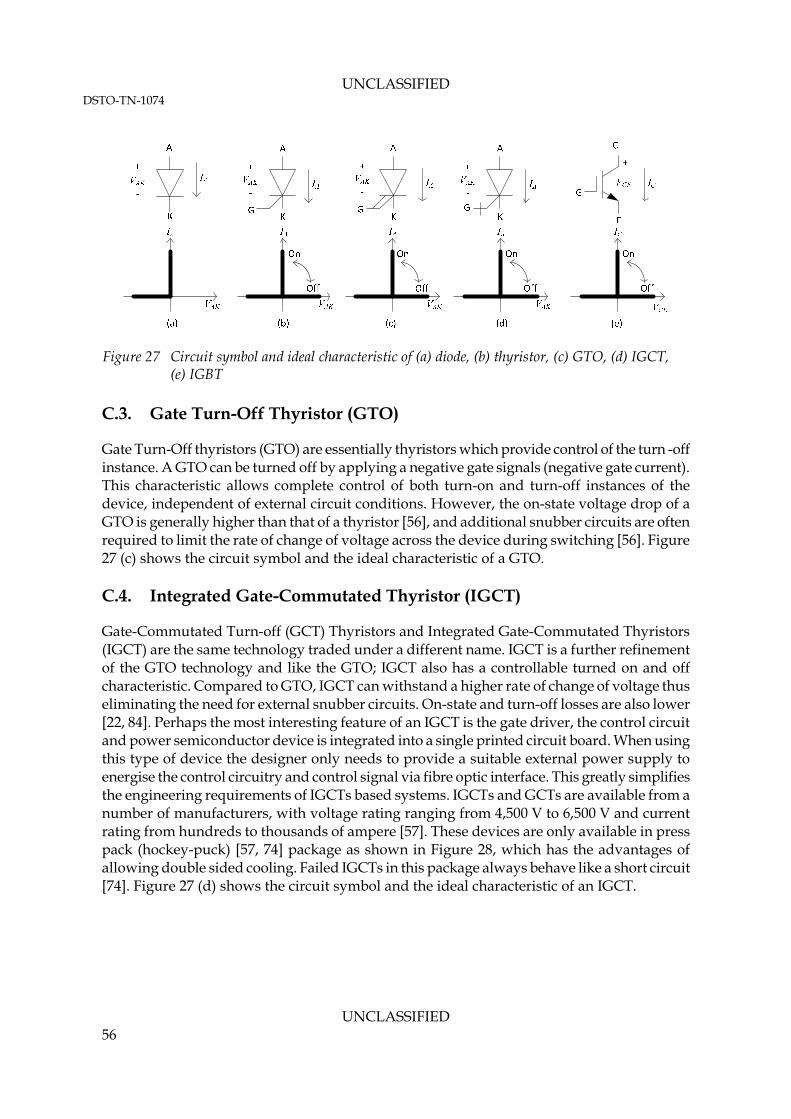
UNCLASSIFIED DSTO-TN-1074
Figure 27 Circuit symbol and ideal characteristic of (a) diode, (b) thyristor, (c) GTO, (d) IGCT, (e) IGBT
C.3. Gate Turn-Off Thyristor (GTO)
Gate Turn-Off thyristors (GTO) are essentially thyristors which provide control of the turn -off instance. A GTO can be turned off by applying a negative gate signals (negative gate current). This characteristic allows complete control of both turn-on and turn-off instances of the device, independent of external circuit conditions. However, the on-state voltage drop of a GTO is generally higher than that of a thyristor [56], and additional snubber circuits are often required to limit the rate of change of voltage across the device during switching [56]. Figure 27 (c) shows the circuit symbol and the ideal characteristic of a GTO. C.4. Integrated Gate-Commutated Thyristor (IGCT)
Gate-Commutated Turn-off (GCT) Thyristors and Integrated Gate-Commutated Thyristors (IGCT) are the same technology traded under a different name. IGCT is a further refinement of the GTO technology and like the GTO; IGCT also has a controllable turned on and off characteristic. Compared to GTO, IGCT can withstand a higher rate of change of voltage thus eliminating the need for external snubber circuits. On-state and turn-off losses are also lower [22, 84]. Perhaps the most interesting feature of an IGCT is the gate driver, the control circuit and power semiconductor device is integrated into a single printed circuit board. When using this type of device the designer only needs to provide a suitable external power supply to energise the control circuitry and control signal via fibre optic interface. This greatly simplifies the engineering requirements of IGCTs based systems. IGCTs and GCTs are available from a number of manufacturers, with voltage rating ranging from 4,500 V to 6,500 V and current rating from hundreds to thousands of ampere [57]. These devices are only available in press pack (hockey-puck) [57, 74] package as shown in Figure 28, which has the advantages of allowing double sided cooling. Failed IGCTs in this package always behave like a short circuit [74]. Figure 27 (d) shows the circuit symbol and the ideal characteristic of an IGCT.
UNCLASSIFIED 56

UNCLASSIFIED DSTO-TN-1074
UNCLASSIFIED 57
Figure 28 Picture of a standard IGCT [85]
C.5. Insulated Gate Bipolar Transistor (IGBT)
Like GTOs, SCRs and IGCTs, Insulated Gate Bipolar Transistors (IGBT) have a controllable on and off characteristic and three terminals - the collector (C) and the emitter (A) are power terminals, and the gate (G) is a control terminal. The control signal of an IGBT is in the form of voltage signals to the gate terminal of the device. When an IGBT is turned on, the resistance between the collector and emitter terminals drops allowing current to conduct. When turned off the resistance and dielectric constant between the collector and emitter is high, blocking the conduction of current (apart from small leakage current). When turned on the primarily loss mechanism of an IGBT is the on-state voltage drop between the collector and emitter terminal, which is caused by the saturation of the junction of the semiconductor device (VCE_SAT). Compared to the three thyristor based devices discussed in this section, an IGBT is able to switch at higher speeds [22, 56] and does not require snubber circuits to limit the rate of change of voltage across the device during switching. However, the on-state voltage drop of high blocking voltage (more than 2,000V) devices are generally more significant than the equivalent IGCT devices [22], which results in higher on-state losses. While an IGBT only allows for uni-directional current flow (collector to emitter), an anti-parallel freewheel diode is often included in the same package, thus allowing bi-direction current flow. The voltage rating of commercially available IGBT ranges from a few hundreds volts to 6,500V, with a current rating of a few hundreds amperes to 3,600A [58]. IGBTs are available in various packages, but for high power applications power module and press pack packages are most common. The failure modes of IGBTs packaged in power modules are not well defined, but will most probably results in a permanent open circuit between the emitter and collector terminals [74]. Failure of a press pack IGBTs always result in short circuit between the power terminals [74]. Figure 27 (e) shows the circuit symbol and the ideal characteristic of an IGBT.

UNCLASSIFIED DSTO-TN-1074
Appendix D: Copyright
This report contains a number of diagrams which are reprinted with permission from their respective copyright owners. This appendix lists these diagrams and acknowledges the copyright of their respective copyright owners. D.1. ABB Asea Brown Boveri Ltd
Figure 5, Figure 12, Figure 14, Figure 15 and Figure 16 are reprinted with permission of ABB Asea Brown Boveri Ltd, with the following copy right notice.
Copyright Notice Permission to use, copy and distribute the documentation published by ABB Group on this World Wide Web server is hereby granted on the condition that each copy contains this copyright notice in its entirety and that no part of the documentation is used for commercial purpose but restricted to use for information purposes within an organization. ALL INFORMATION PUBLISHED ON THIS WORLD WIDE WEB SERVER IS PROVIDED AS IS WITHOUT ANY REPRESENTATION OR WARRANTY OF ANY KIND EITHER EXPRESS OR IMPLIED INCLUDING BUT NOT LIMITED TO IMPLIED WARRANTIES FOR MERCHANTABILITY, FITNESS FOR A PARTICULAR PURPOSE OR NON-INFRINGEMENT. ANY ABB DOCUMENTATION MAY INCLUDE TECHNICAL INACCURACIES OR TYPOGRAPHICAL ERRORS. CHANGES AND ADDITIONS MAY BE MADE BY ABB FROM TIME TO TIME TO ANY INFORMATION CONTAINED HEREIN. D.2. The Institution of Engineering and Technology
Figure 9, Figure 10, Figure 11 and Figure 13 are originally from: Flurscheim, C. H. (1982) Power circuit breaker theory and design. 2nd ed, Stevenage: Peregrinus on behalf of the Institution of Electrical Engineers They are reprinted with permission from The Institution of Engineering and Technology, London, United Kingdom. D.3. CRC Press LLC – Taylor & Francis Group LCC - Books
Figure 17, Figure 18 and Figure 25 are originally from: Slade, P. G. (1999) Electrical Contacts: Principles and Applications. 1st ed. Boca Raton, CRC Press They are reprinted with permission from Taylor & Francis Group LCC – Books.
UNCLASSIFIED 58

Page classification: UNCLASSIFIED
DEFENCE SCIENCE AND TECHNOLOGY ORGANISATION
DOCUMENT CONTROL DATA 1. PRIVACY MARKING/CAVEAT (OF DOCUMENT) FOR OFFICIAL USE ONLY
2. TITLE Review of DC Circuit Breakers for Submarine Applications
3. SECURITY CLASSIFICATION (FOR UNCLASSIFIED REPORTS THAT ARE LIMITED RELEASE USE (L) NEXT TO DOCUMENT CLASSIFICATION) Document (U) Title (U) Abstract (U)
4. AUTHOR(S) Wang Y. Kong
5. CORPORATE AUTHOR DSTO Defence Science and Technology Organisation 506 Lorimer St Fishermans Bend Victoria 3207 Australia
6a. DSTO NUMBER DSTO-TN-1074
6b. AR NUMBER AR-015-254
6c. TYPE OF REPORT Technical Note
7. DOCUMENT DATE March 2012
8. FILE NUMBER 2011/1236626/1
9. TASK NUMBER NAV 07/360
10. TASK SPONSOR DGSMC
11. NO. OF PAGES 64
12. NO. OF REFERENCES 85
13. DSTO Publications Repository http://dspace.dsto.defence.gov.au/dspace/
14. RELEASE AUTHORITY Chief, Maritime Platforms Division
15. SECONDARY RELEASE STATEMENT OF THIS DOCUMENT
Approved for public release OVERSEAS ENQUIRIES OUTSIDE STATED LIMITATIONS SHOULD BE REFERRED THROUGH DOCUMENT EXCHANGE, PO BOX 1500, EDINBURGH, SA 5111 16. DELIBERATE ANNOUNCEMENT No Limitations 17. CITATION IN OTHER DOCUMENTS Yes 18. DSTO RESEARCH LIBRARY THESAURUS Submarines, Circuit breakers, Electric switches, Semiconductor technology, Reviews, Literature surveys, Power equipment 19. ABSTRACT The Defence Science and Technology Organisation (DSTO) has undertaken a review of direct current (dc) circuit breakers for submarines as a deliverable under the System Integration (SI) Corporate Enabling Research Program (CERP). This review is conducted to support evaluation of dc circuit breaker options for future submarines.
Page classification: UNCLASSIFIED