review of digital design with vhdl - university of arkansas · review of digital design with vhdl....
TRANSCRIPT

Review of Digital Designwith VHDL

Digital World
Digital world is a world of ‘0’ and ‘1’ Each binary digit is called a bit Eight consecutive bits are called a byte
Hexadecimal (base 16) representation for convenience 0,1,2,3,4,5,6,7,8,9,A,B,C,D,E,F Each hexadecimal digital represents 4 binary bits
Basic operations for values in hexadecimal representation Addition Subtraction

Overview
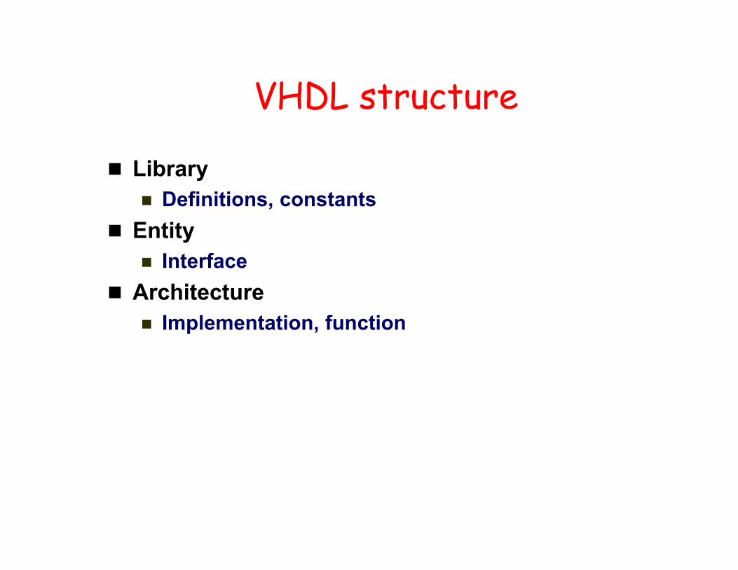
VHDL structure
Library Definitions, constants
Entity Interface
Architecture Implementation, function

Libraries
Library ieee;
Use ieee.std_logic_1164.all; Use ieee.std_logic_arith.all; Use ieee.std_logic_signed.all; Use ieee.std_logic_unsigned.all;

VHDL - Library
Include library
library IEEE; Define the library package used
use IEEE.STD_LOGIC_1164.all; Define the library file used For example, STD_LOGIC_1164 defines ‘1’ as logic
high and ‘0’ as logic low output <= ‘1’; --Assign logic high to output

VHDL - Entity
Interface for communication among different modules / components
Define the signal port modes (INPUT and OUTPUT)

VHDL - Entity
Input port can only be read inside architecture input1 <= temp; -- This statement is NOT allowed
Output port can only be written inside architecture temp <= output1; -- This statement is NOT allowed
output <= inputa and inputb; output is assigned to be inputa AND inputb

Entity
Define inputs and outputs Example:
Entity test isPort( A,B,C,D: in std_logic;
E: out std_logic);End test;

Architecture
Define functionality of the component
X <= A AND B; Y <= C AND D; E <= X OR Y;
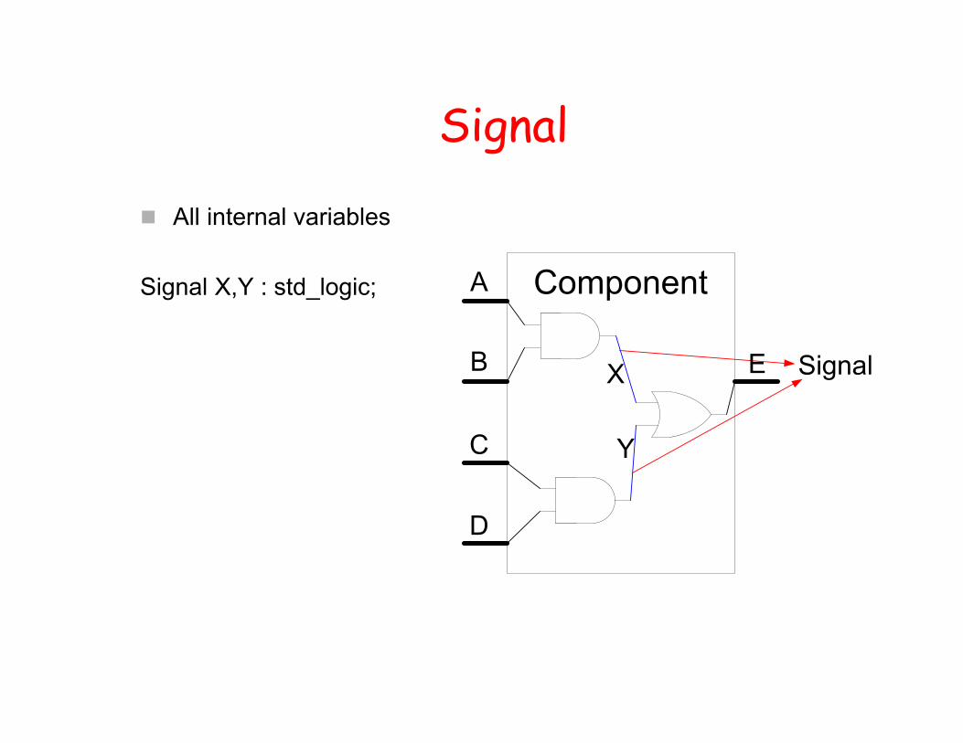
Signal
All internal variables
Signal X,Y : std_logic;

Final codeLIBRARY IEEE;USE IEEE.STD_LOGIC_1164.ALL;
ENTITY TEST ISPORT (A,B,C,D : IN STD_LOGIC;
E : OUT STD_LOGIC);END TEST;
ARCHITECTURE BEHAVIOR OF TEST ISSIGNAL X,Y : STD_LOGIC;
BEGIN
X <= A AND B;Y <= C AND D;E <= X OR Y;
END BEHAVIOR;

VHDL features Case insensitive
inputa, INPUTA and InputA are refer to the same variable Comments
‘--’ until end of line If you want to comment multiple lines, ‘--’ need to be put at the
beginning of every single line Statements are terminated by ‘;’ Signal assignment:
‘<=’ Variable assignment:
‘:=’ User defined names:
letters, numbers, underscores (‘_’) start with a letter

Different ways to describe a digital system in VHDL
Description of a complex system is typically a mix of both behavioral description and structural description

Behavior Description
WARNING <= (not DOOR and IGNITION) or (not SBELT and IGNITION)

Structural Descriptionarchitecture structural of BUZZER is
-- Declarationscomponent AND2
port (in1, in2: in std_logic;out1: out std_logic);
end component;component OR2
port (in1, in2: in std_logic;out1: out std_logic);
end component;component NOT1
port (in1: in std_logic;out1: out std_logic);
end component;-- declaration of signals used to interconnect gatessignal DOOR_NOT, SBELT_NOT, B1, B2: std_logic;
begin -- Component instantiations statementsU0: NOT1 port map (DOOR, DOOR_NOT);U1: NOT1 port map (SBELT, SBELT_NOT);U2: AND2 port map (IGNITION, DOOR_NOT, B1);U3: AND2 port map (IGNITION, SBELT_NOT, B2);U4: OR2 port map (B1, B2, WARNING);
end structural;

Port Map
Chip1 : Chip_APort map (A,B,C,X,Y);
Chip2 : Chip_BPort map (X,Y,D,E);
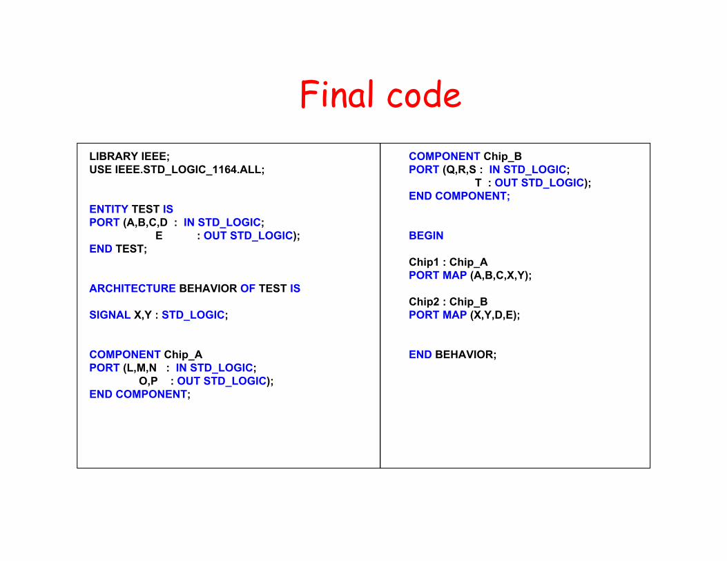
Final codeLIBRARY IEEE;USE IEEE.STD_LOGIC_1164.ALL;
ENTITY TEST ISPORT (A,B,C,D : IN STD_LOGIC;
E : OUT STD_LOGIC);END TEST;
ARCHITECTURE BEHAVIOR OF TEST IS
SIGNAL X,Y : STD_LOGIC;
COMPONENT Chip_APORT (L,M,N : IN STD_LOGIC;
O,P : OUT STD_LOGIC);END COMPONENT;
COMPONENT Chip_BPORT (Q,R,S : IN STD_LOGIC;
T : OUT STD_LOGIC);END COMPONENT;
BEGIN
Chip1 : Chip_APORT MAP (A,B,C,X,Y);
Chip2 : Chip_BPORT MAP (X,Y,D,E);
END BEHAVIOR;
Port Mapping
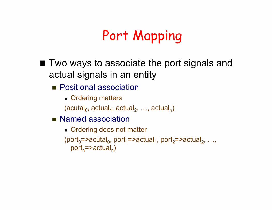
Two ways to associate the port signals and actual signals in an entity Positional association
Ordering matters(acutal0, actual1, actual2, …, actualn)
Named association Ordering does not matter(port0=>acutal0, port1=>actual1, port2=>actual2, …,
portn=>actualn)

Structural Modeling
Declare a list of components being used Declare signals which define the nets (i.e., wires)
that interconnect components Label multiple instances of the same component
so that each instance is uniquely definedarchitecture architecture_name of NAME_OF_ENTITY is
-- Declarationscomponent declarationssignal declarations
begin-- Statements
component instantiation and connections::
end architecture_name;

Component Declaration
Before components can be instantiated they need to be declared in the architecture declaration sectioncomponent component_name [is]
[port ( port_signal_names: mode type;port_signal_names: mode type;
:port_signal_names: mode type);]
end component [component_name];
component OR2port (in1, in2: in std_logic;
out1: out std_logic);end component;

Component Instantiation and Interconnections
The component instantiation statement references a component that can be Previously defined at the current level of the hierarchy Defined in a technology library (e.g., vendor’s library)
instance_name : component_name port map (port1=>signal1, port2=> signal2,… port3=>signaln);
instance_name : component_name port map (signal1, signal2,… signaln);
component NAND2port (in1, in2: in std_logic;
out1: out std_logic);end component;signal int1, int2, int3: std_logic;
:U1: NAND2 port map (A,B,int1);U2: NAND2 port map (in1=>C, in2=>D, out1=>int2);U3: NAND3 port map (int1, int2, Z);

Data Objects Constant
A constant can have a single value of a given type and cannot be changed
Constants declared at the start of an architecture can be used anywhere within the architecture
Constants declared within a process can only be used inside that specific process
constant list_of_name_of_constant: type [ := initial value] ;
constant RISE_FALL_TME: time := 2 ns;constant DELAY1: time := 4 ns;constant RISE_TIME, FALL_TIME: time:= 1 ns;constant DATA_BUS: integer:= 16;

Data Objects Variable
can be updated using a variable assignment statement
is updated without any delay as soon as the statement is executed
must be declared inside a process is local to the process
variable list_of_variable_names: type [ := initial value] ;
variable CNTR_BIT: bit :=0;variable VAR1: boolean :=FALSE;variable SUM: integer range 0 to 256 :=16;variable STS_BIT: bit_vector (7 downto 0);
Variable_name := expression;

Data Objects Signal
Represent wires and storage elements Declared inside the architecture, outside the process Updated when the signal assignment statement is
executed, after a certain delaysignal_name <= expression;
signal list_of_signal_names: type [ := initial value] ;
signal SUM, CARRY: std_logic;signal CLOCK: bit;signal TRIGGER: integer :=0;signal DATA_BUS: bit_vector (0 to 7);signal VALUE: integer range 0 to 100;
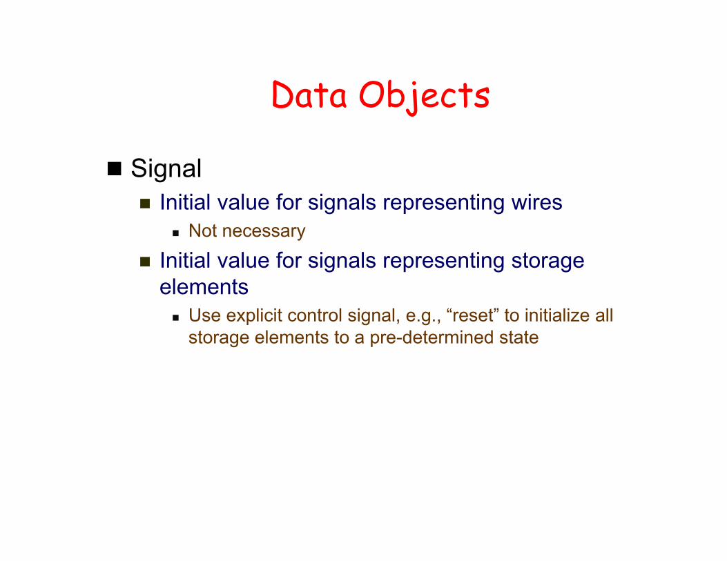
Data Objects
Signal Initial value for signals representing wires
Not necessary
Initial value for signals representing storage elements Use explicit control signal, e.g., “reset” to initialize all
storage elements to a pre-determined state
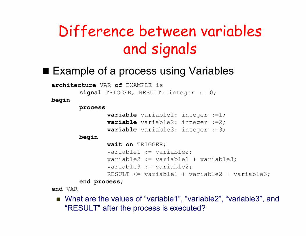
Difference between variables and signals
Example of a process using Variables
What are the values of “variable1”, “variable2”, “variable3”, and “RESULT” after the process is executed?
architecture VAR of EXAMPLE issignal TRIGGER, RESULT: integer := 0;
beginprocess
variable variable1: integer :=1;variable variable2: integer :=2;variable variable3: integer :=3;
beginwait on TRIGGER;variable1 := variable2;variable2 := variable1 + variable3;variable3 := variable2;RESULT <= variable1 + variable2 + variable3;
end process;end VAR

Difference between variables and signals
Example of a process using Signals
What are the values of “signal1”, “signal2”, “signal3”, and “RESULT” after the process is executed?
architecture SIGN of EXAMPLE issignal TRIGGER, RESULT: integer := 0; signal signal1: integer :=1;signal signal2: integer :=2;signal signal3: integer :=3;
beginprocessbegin
wait on TRIGGER;signal1 <= signal2;signal2 <= signal1 + signal3;signal3 <= signal2;RESULT <= signal1 + signal2 + signal3;
end process;end SIGN;

Data Types bit values: '0', '1' boolean values: TRUE, FALSE integer values: -(231) to +(231 - 1)
std_logic values: 'U','X','1','0','Z','W','H','L','-' ‘U' = uninitialized'X' = unknown'W' = weak ‘X’'Z' = floating'H'/'L' = weak '1'/'0’'-' = don't care
Std_logic_vector (n downto 0); Std_logic_vector (0 upto n);

Concurrency in the Architecture
A statement will be executed when one or more of the signals on the right hand side change their value
A process will be executed if there is any change in the value of the signals in the sensitivity list
architecture architecture_name of NAME_OF_ENTITY is-- Declarations
-- components declarations-- signal declarations
:
begin-- Statements-- Processes
:
end architecture_name;

Process All statements in a process occur sequentially
The values of signals are assigned after a delay Processes typically have sensitivity list
If the sensitivity list is not specified, one has to include a wait statement to make sure that the process will halt
Cannot include both a sensitivity list and a wait statement Processes are used to model both sequential circuits and
combinational circuits
Process (A,B,C)Begin
statements;End process;

Process Statement
[process_label:] process [ (sensitivity_list) ] [is][ process_declarations]
beginlist of sequential statements such as:
signal assignmentsvariable assignmentscase statementexit statementif statementloop statementnext statementnull statementprocedure call wait statement
end process [process_label];
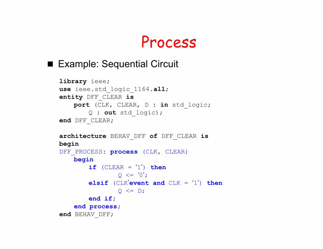
Process Example: Sequential Circuit
library ieee;use ieee.std_logic_1164.all;entity DFF_CLEAR is
port (CLK, CLEAR, D : in std_logic;Q : out std_logic);
end DFF_CLEAR;
architecture BEHAV_DFF of DFF_CLEAR isbeginDFF_PROCESS: process (CLK, CLEAR)
beginif (CLEAR = ‘1’) then
Q <= ‘0’;elsif (CLK’event and CLK = ‘1’) then
Q <= D;end if;
end process;end BEHAV_DFF;

Process Example: Combinational Circuitlibrary ieee;use ieee.std_logic_1164.all;entity FULL_ADDER is
port (A, B, Cin : in std_logic;Sum, Cout : out std_logic);
end FULL_ADDER;
architecture BEHAV_FA of FULL_ADDER issignal int1, int2, int3: std_logic;begin-- Process P1 that defines the first half adderP1: process (A, B)
beginint1<= A xor B;int2<= A and B;
end process;-- Process P2 that defines the second half adder and the OR -- gateP2: process (int1, int2, Cin)
beginSum <= int1 xor Cin;int3 <= int1 and Cin;Cout <= int2 or int3;
end process;end BEHAV_FA;
Process
Test How to use process to model a multiplexer?
VHDL language elements
VHDL is composed of language building blocks that consist of more than 75 reserved words and about 200 descriptive
words or word combinations
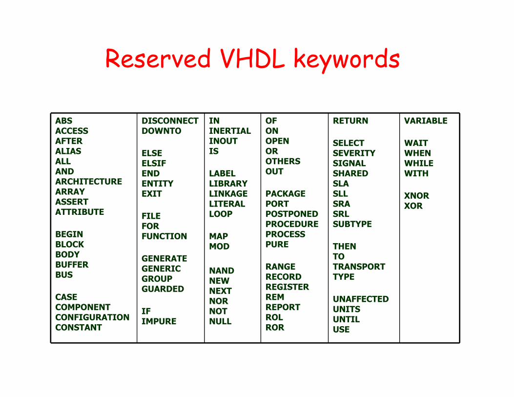
Reserved VHDL keywords
VARIABLE
WAITWHENWHILEWITH
XNORXOR
RETURN
SELECTSEVERITYSIGNALSHAREDSLASLLSRASRLSUBTYPE
THENTOTRANSPORTTYPE
UNAFFECTEDUNITSUNTILUSE
OFONOPENOROTHERSOUT
PACKAGEPORTPOSTPONEDPROCEDUREPROCESSPURE
RANGERECORDREGISTERREMREPORTROLROR
ININERTIALINOUTIS
LABELLIBRARYLINKAGELITERALLOOP
MAPMOD
NANDNEWNEXTNORNOTNULL
DISCONNECTDOWNTO
ELSEELSIFENDENTITYEXIT
FILEFORFUNCTION
GENERATEGENERICGROUPGUARDED
IFIMPURE
ABSACCESSAFTERALIASALLANDARCHITECTUREARRAYASSERTATTRIBUTE
BEGINBLOCKBODYBUFFERBUS
CASECOMPONENTCONFIGURATION CONSTANT
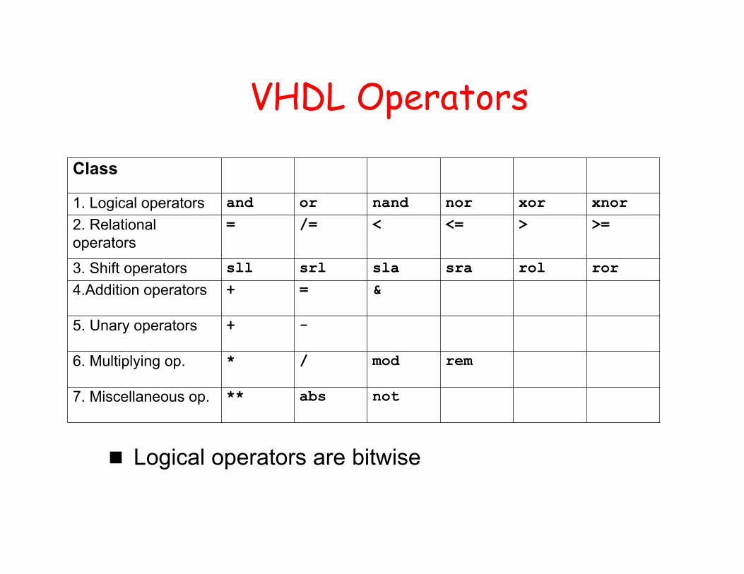
VHDL Operators
Logical operators are bitwise
Class
1. Logical operators and or nand nor xor xnor
2. Relational operators
= /= < <= > >=
3. Shift operators sll srl sla sra rol ror
4.Addition operators + = &
5. Unary operators + -
6. Multiplying op. * / mod rem
7. Miscellaneous op. ** abs not

reference
VHDL Tutorial Jan Van der Spiegel, University of Pennsylvania http://www.seas.upenn.edu/~ese171/vhdl/vhdl_primer.
html