review of modeling approaches to groundwater flow in
TRANSCRIPT

Review Paper/
Review of Modeling Approaches to GroundwaterFlow in Deformed Carbonate Aquifersby Giacomo Medici1, Luca Smeraglia2, Anita Torabi3,4, and Chartlotte Botter5
AbstractWe discuss techniques to represent groundwater flow in carbonate aquifers using the three existing modeling
approaches: equivalent porous medium, conduit network, and discrete fracture network. Fractures in faultedstratigraphic successions are characterized by dominant sets of sub-vertical joints. Grid rotation is recommendedusing the equivalent porous medium to match higher hydraulic conductivity with the dominant orientation ofthe joints. Modeling carbonate faults with throws greater than approximately 100 m is more challenging. Suchfaults are characterized by combined conduit-barrier behavior. The barrier behavior can be modeled using theHorizontal Flow Barrier Package with a low-permeability vertical barrier inserted to represent the impediment ofhorizontal flow in faults characterized by sharp drops of the piezometric surface. Cavities can occur parallel tothe strike of normal faults generating channels for the groundwater. In this case, flow models need to account forturbulence using a conduit network approach. Channels need to be embedded in an equivalent porous mediumdue to cavities a few centimeters large, which are present in carbonate aquifers even in areas characterized by lowhydraulic gradients. Discrete fracture network modeling enables representation of individual rock discontinuitiesin three dimensions. This approach is used in non-heavily karstified aquifers at industrial sites and was recentlycombined with the equivalent porous medium to simulate diffusivity in the matrix. Following this review, werecommend that the future research combines three practiced modeling approaches: equivalent porous medium,discrete fracture network, and conduit network, in order to capture structural and flow aspects in the modeling ofgroundwater in carbonate rocks.
1G360 Institute for Groundwater Research, College ofEngineering and Physical Science, University of Guelph, Guelph,Ontario, N1G 2W1, Canada
2Instituto di Geologia Ambientale e Geoingegneria, ConsiglioNazionale delle Ricerche, Piazzale Aldo Moro, 00185, Rome, Italy
3Department of Geosciences, University of Oslo, Postboks 1047Blindern, 0316, Oslo, Norway
4Corresponding author: Department of Geosciences, Universityof Oslo, Postboks 1047 Blindern, 0316 Oslo, Norway;[email protected]
5School of Earth and Environment, University of Leeds,Woodhouse Lane, Leeds, West Yorkshire, LS2 9JT, UK
Received June 2020, accepted December 2020.© 2020 The Authors. Groundwater published by Wiley Periodi-
cals LLC on behalf of National Ground Water Association.This is an open access article under the terms of the Creative
Commons Attribution-NonCommercial License, which permits use,distribution and reproduction in any medium, provided the originalwork is properly cited and is not used for commercial purposes.
doi: 10.1111/gwat.13069
IntroductionFractured carbonate aquifers, which are subjected
to different degrees of karstification, underlie a landarea covering approximately 15% of the earth’s surface,and they supply drinking water to approximately 25%of the world’s population (see Figure 1; Flugel 2013).Approximately 45%, 40%, and 30% of the earth’s sur-face are covered by carbonate rocks in China, northernAmerica, and Europe, respectively (Figure 1; Worthing-ton and Ford 2009; Ford and Williams 2013; Hartmannet al. 2014a, 2014b). In these areas, stress on groundwaterresources is much higher due to high population densities,which necessitate intense industrial and agricultural activ-ities. Thus, a range of pollutants such as nitrate, sulfate,chloride, pathogens, toxic organic compounds released bymineral fertilizers and pesticides can reach the saturatedparts of these aquifers in regions, which are devolvedto industry and agriculture (Bales et al. 1989; Goppert
NGWA.org Groundwater 1

and Goldscheider 2008; Mahler and Garner 2009; Petittaet al. 2009, 2018; Musgrove et al. 2014; Zhang et al. 2019;Medici et al. 2020). Additionally, carbonate aquifers rep-resent the principal source of water for major capitalcities such as Doha, Beijing, London, Rome, and Vienna(Maloszewski et al. 2002; Worthington and Gunn 2009;Ford and Williams 2013; Hartmann et al. 2014a, 2014b;Worthington 2015). Hence, the exponential geo-modelingadvance of the last 30 years has presented new solutionsfor the representation of groundwater flow in aquifersof carbonate origin in response to the social and eco-nomic importance of these geological media (Shoemakeret al. 2008; Reimann and Hill 2009; Hill et al. 2010; Gal-legos et al. 2013; Saller et al. 2013; Hartmann et al. 2014a;Sullivan et al. 2019). However, new modeling advancesshould be integrated with traditional techniques for rig-orous representation of fluid flow in a three-dimensional(3D) geological domain. Further, all modeling techniquesshould honor the corresponding tectonic settings.
Within carbonate aquifers, fluid flow is primarilycontrolled by bedding planes reactivated by the tec-tonic stress (Tanner 1989; Ritzi and Andolsek 1992;Bidaux and Drogue 1993; Odling et al. 1999; Baueret al. 2016; Medici et al. 2016, 2019a, 2019c). Groundwa-ter flow is particularly rapid in areas of intense fracturingsuch as damage zones of normal faults and thrusts andintensely fractured fold hinges and limbs. In these set-tings, karstification can be much more intense, whereconduits characterized by turbulent flow occur in the sub-surface (Shoemaker et al. 2008; Goppert et al. 2011;Amoruso et al. 2013; Chen and Goldscheider 2014;Medici et al. 2019b). Such conduits have been detected byteleviewer logging and persist in carbonate aquifers at dif-ferent depths (∼10–200 m) below the water table (Gold-scheider and Drew 2014; Medici et al. 2019a). Hence, car-bonate aquifers are characterized by a complex 3D patternof bedding planes, tectonic fractures, and karst conduits.Currently, three different approaches are used to modelfluid flow in this structural complexity: equivalent porousmedium (EPM), conduit network (CN), and discrete frac-ture network (DFN) (Selroos et al. 2002). The simplestmodeling approach is EPM. This method treats the frac-tured rock with channels as an EPM, using bulk proper-ties instead of the physical characteristics of the matrix,individual fractures and conduits (Yager et al. 2009). Bycontrast, the DFN and CN approaches represent ground-water flow in individual fractures and channels, respec-tively (Shoemaker et al. 2008; Parker et al. 2019). Theseapproaches are impaired, as they overlook the structuralfeatures and their effects on the fluid flow in different tec-tonic settings. As contaminants are transported at higherrates in rock discontinuities of primary tectonic origin,much more attention is needed on the structural geologyaspect of the conceptual model than merely the numer-ical components of groundwater flow models in carbon-ate aquifers (Odling et al. 1999; Aydin 2000; Lemieuxet al. 2006; Lacombe and Burton 2010; Wang et al. 2017).
To account for both recent advances in modelingfluid flow in the subsurface and the brittle structural
behavior of carbonate rocks, a first review that combinesthe two aspects is here proposed. Fault geometry andarchitectural studies by structural geologists concerningthe potential influence of faults on fluid flow are mostlybased on outcrop observations and geophysical data frompetroleum reservoirs (see Faulkner et al. 2010, and Solumand Huisman 2016 for reviews). Bense et al. (2013)reviewed all the experimental methods of hydraulicinvestigation of fault zones. Fiorillo et al. (2015) studiedthe recession of springs in karst aquifers worldwidefrom a hydrological point of view. A number of reviewpapers focus on the hydraulic behavior of fractured andkarst aquifers in specific regions (e.g., Ghasemizadehet al. 2012; Guo et al. 2013).
Other recent reviews focus on the links betweenpaleoclimate and ecosystem and the hydrogeology ofcarbonate aquifers (Goldscheider 2012; Hartmann andBaker 2017). Applicability of karst aquifers to low andmedium enthalpy geothermal resources were revised byGoldscheider et al. (2010), Hartmann et al. (2014a), andKalhor et al. (2019) that provide a review of the mostrecent modeling approaches to karst hydrology. However,these works do not relate modeling approaches to thetectonic structures and exclusively discuss the use of EPMand CN methodologies.
Similar to other authors, we consider fractured car-bonate aquifers strongly anisotropic and heterogeneousdue to the coupling of pervasive fracturing and kars-tification (Worthington 1991; West and Odling 2007;Goldscheider and Drew 2014; Hartmann et al. 2014a;Borovic et al. 2019). However, the majority of ground-water flow models only account for the vertical flowanisotropy (K h /K v ), which is in a wide range (∼102 –103)in karst environments (Neymeyer et al. 2007; Odlinget al. 2013; Goldscheider and Drew 2014; Zuffiano et al.2016).
Anticlines, synclines, and areas affected by verticallithosphere uplifts are characterized by dominant setsof sub-vertical joints (Odling et al. 1999; Gillespieet al. 2001; Billi 2005; Carminati et al. 2010; Tavaniet al. 2015). These structural patterns can induce hori-zontal flow anisotropies that influence the direction andrate of contaminant dispersal in the subsurface. Shapeand velocities of plumes are influenced by preferentialorientation of tectonic fractures in geological porousmedia (Odling and Roden 1997; Berkowitz 2002). Thishorizontal flow anisotropy (K y /K x ) also finds practicalapplication in the definition of the source protection areasin karst aquifers. In fact, backwards particle trackingfrom abstraction wells is influenced by the introductionof horizontal flow anisotropies in 3D groundwater flowmodels (Pollock 1994).
Extensional tectonic settings, fold and thrust belts,and vertically uplifted areas are characterized by normalfaults that accommodate local or crustal scale extension(Jolivet and Faccenna 2000; Billi 2005; Carminatiet al. 2009). Hence, conceptual and technical details onmodeling groundwater flow in normal faults are added inthis research.
2 G. Medici et al. Groundwater NGWA.org

Figure 1. World map with outcrops of carbonate rocks (from Flugel 2013).
In summary, utilizing the EPM and DFN methods,this review links groundwater flow modeling to thestructural pattern in the saturated zone of carbonate aquifertypes. Specific research objectives are: (1) to provideguidelines to model groundwater flow in the subsurfacein the presence of normal faults, folds, thrusts, and uplift-generated joints; (2) to relate modeling strategy to theexisting flow modeling approaches in geological media;and (3) to identify future research scenarios on numericalmodeling in carbonate aquifers.
Hydrogeology of Tectonic StructuresThe 3D network of rock discontinuities and karst con-
duits in faulted and unfaulted areas are described based onstructural, geo-morphological surveys and speleologicalobservations. This description, coupled with experimen-tal evidences of the impact of thrusts, folds, and normalfaults on fluid flow, represents a primary step before mov-ing toward numerical modeling. Flow anisotropies arethe result of dominant sets of tectonic fractures in car-bonates aquifers (Odling et al. 1999, 2013; Billi 2005;Hartmann et al. 2007; Agosta et al. 2010; Kornevaet al. 2014). However, flow heterogeneities are repre-sented by systems of caves and cavities that due torelatively large aperture (∼10−2 –100 m) are character-ized by high-flow velocities and turbulent flow (Baueret al. 2003; Shoemaker et al. 2008; Gallegos et al. 2013;Masciopinto and Palmiotta 2013; Saller et al. 2013; Sauroet al. 2013; Medici et al. 2019a, 2019b). The followingsection describes the relation between flow anisotropies,heterogeneities, and tectonic structures.
Fold and Thrust BeltsFolds can form in association with detachments,
as well as propagating and bending faults (e.g., All-mendinger 1998; Carminati et al. 2010). Thrust faults andfolds (anticlines and synclines) observed at a much finerscale (∼100 –101 m) appear heavily fractured and karsti-fied in quarries and road cuts (Billi et al. 2007; Pepe andParise 2014; Tavani et al. 2015; Bauer et al. 2016; Medici
Figure 2. Three-dimensional hydro-structural model ofthrusts (modified from Goldscheider and Drew 2014).
et al. 2019b; Smeraglia et al. 2020). Hence, understand-ing preferential orientation of fractures as conduits is ofparamount importance to model groundwater flow in thesubsurface in mountain belts (Petitta and Tallini 2002;Falcone et al. 2008; Goppert et al. 2011; Bakalowicz2015).
Thrusts that displace carbonate sedimentary succes-sions are typically characterized by an alignment ofsprings (Figure 2). Troughs, where the springs are located,are used to map thrusts in vegetated areas in a moun-tain range. The alignments of springs arise from eitherpresence of relatively impermeable marly lithologies atfootwall blocks or development of low-permeability coresin the thrust plane (Boni et al. 1986; Cosentino et al. 2010;Giacopetti et al. 2017).
Springs are connected to a network of caves and cavi-ties in the subsurface (Scozzafava and Tallini 2001; Sauroet al. 2013; Goldscheider and Drew 2014; Giacopettiet al. 2017). Such conduits are approximately 0.1–5 mlarge according to outcrop and speleological observationsand tend to be orthogonal to the thrust faults (Figure 2).This orientation is attributed to the development of valleysthat perpendicularly cut the compressional front. Most ofthese valleys are related to strike-slip tear faults that dividesectors of thrusts characterized by different displacements(Figure 2b; Boyer and Elliot 1982; Miccadei et al. 2011).Here, relatively high groundwater flow velocities and tur-bulence occurs. In fact, high turbidity of springs associ-ated with major thrusts is due to turbulent currents that
NGWA.org G. Medici et al. Groundwater 3

Figure 3. Hydrogeology versus folds: (a) hydro-structural model of anticlines and synclines (modified from Tavani et al. 2015);(b) map of Italy with location of outcrops in (c) and (d); (c) sub-vertical fold-related fractures, Vivaro Romano (Latium, CentralItaly); (d) karstification of sub-vertical fold-related fractures, Vivaro Romano (Latium, Central Italy).
resuspend solid particles (Angelini and Dragoni 1997;Amraoui et al. 2003).
Rock discontinuities in anticline and syncline struc-tures in fold and thrust belts are dominated by openfractures oriented perpendicular to bedding surfaces andstriking parallel and oblique to fold axis (see Figure 3aand d). These high angle rock discontinuities are hydrauli-cally conductive (Figure 3c and d). Minor faults (throw< ∼10 m) also form in the fold hinge zone. Stylolites,which represent typical fluid flow barriers, are perva-sively oriented sub-parallel to fold hinge (Figure 3a; Tondiet al. 2006; Carminati et al. 2010; Tavani et al. 2015). Asa consequence, hydraulic conductivity tends to be higherparallel to the fold axis (Figure 3a). The orientation offolds axis can be considered constant at the scale ofapproximately 0.5–5 km according to geological maps infolded areas (Santantonio et al. 2017; Mercuri et al. 2020).At this spatial scale of a few kilometers, contaminantplumes are constrained by geophysical monitoring atindustrial field sites (Chapman and Parker 2005; Parkeret al. 2008). Hence, the hydro-mechanical anisotropy ofanticlines and synclines may influence spatial extensionand dispersal rate of these plumes in the subsurface.
However, in mountain belts, anticlines and synclinesplay a different hydrogeological role. Typically, anticlinesrepresent topographic highs that approximately coincidewith groundwater divides (Cosentino et al. 2010; Lauberand Goldscheider 2014). Synclines more commonlyrepresent valleys, and therefore, hydraulic gradients and
modulus of the groundwater flow vector are elevated dueto the steep topography (Goldscheider 2005; Worthingtonand Ford 2009; Chen and Goldscheider 2014; Lauberand Goldscheider 2014). Here, rapid groundwater flowoccurs and facilitates rock dissolution with vigorousand continuous refreshment of groundwater, which isless saturated in calcite, aragonite, and dolomite. Thus,karstification occurs and tends to be sub-parallel to thesyncline axis (Worthington 1991; Goldscheider 2005). Themaximum hydraulic conductivity and flow vectors areapproximately sub-parallel to the preferential orientationof open fractures according to hydro-mechanical models(Figure 3a; Carminati et al. 2010; Evans and Fischer 2012;Chen and Goldscheider 2014; Tavani et al. 2015). Thecoupling between groundwater flow direction and its highrate in the valleys explains the presence of karst conduitsparallel to the syncline axis.
Conduits have been detected parallel to the synclinestructures in the Canadian Rocky Mountains and the Aus-trian and German Alps (Worthington 1991; Goldschei-der 2005; Gremaud et al. 2009; Chen and Goldschei-der 2014). Here, tracer tests indicate high-flow velocitiesup to 200 m/h in valleys where synclines are mapped(Worthington 1991; Goppert and Goldscheider 2008).
Unfaulted Uplifted AreasAreas of the world characterized by sub-horizontal
layers (<5◦) and absence of compressional tectonic struc-tures are deformed by gentle flexuring of geologicalstrata due to vertical uplifts of the lithosphere (Carminati
4 G. Medici et al. Groundwater NGWA.org
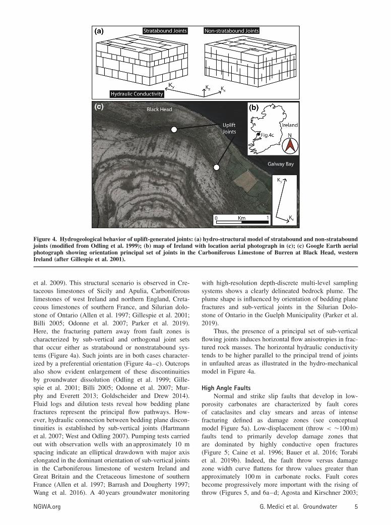
Figure 4. Hydrogeological behavior of uplift-generated joints: (a) hydro-structural model of stratabound and non-strataboundjoints (modified from Odling et al. 1999); (b) map of Ireland with location aerial photograph in (c); (c) Google Earth aerialphotograph showing orientation principal set of joints in the Carboniferous Limestone of Burren at Black Head, westernIreland (after Gillespie et al. 2001).
et al. 2009). This structural scenario is observed in Cre-taceous limestones of Sicily and Apulia, Carboniferouslimestones of west Ireland and northern England, Creta-ceous limestones of southern France, and Silurian dolo-stone of Ontario (Allen et al. 1997; Gillespie et al. 2001;Billi 2005; Odonne et al. 2007; Parker et al. 2019).Here, the fracturing pattern away from fault zones ischaracterized by sub-vertical and orthogonal joint setsthat occur either as stratabound or nonstratabound sys-tems (Figure 4a). Such joints are in both cases character-ized by a preferential orientation (Figure 4a–c). Outcropsalso show evident enlargement of these discontinuitiesby groundwater dissolution (Odling et al. 1999; Gille-spie et al. 2001; Billi 2005; Odonne et al. 2007; Mur-phy and Everett 2013; Goldscheider and Drew 2014).Fluid logs and dilution tests reveal how bedding planefractures represent the principal flow pathways. How-ever, hydraulic connection between bedding plane discon-tinuities is established by sub-vertical joints (Hartmannet al. 2007; West and Odling 2007). Pumping tests carriedout with observation wells with an approximately 10 mspacing indicate an elliptical drawdown with major axiselongated in the dominant orientation of sub-vertical jointsin the Carboniferous limestone of western Ireland andGreat Britain and the Cretaceous limestone of southernFrance (Allen et al. 1997; Barrash and Dougherty 1997;Wang et al. 2016). A 40 years groundwater monitoring
with high-resolution depth-discrete multi-level samplingsystems shows a clearly delineated bedrock plume. Theplume shape is influenced by orientation of bedding planefractures and sub-vertical joints in the Silurian Dolo-stone of Ontario in the Guelph Municipality (Parker et al.2019).
Thus, the presence of a principal set of sub-verticalflowing joints induces horizontal flow anisotropies in frac-tured rock masses. The horizontal hydraulic conductivitytends to be higher parallel to the principal trend of jointsin unfaulted areas as illustrated in the hydro-mechanicalmodel in Figure 4a.
High Angle FaultsNormal and strike slip faults that develop in low-
porosity carbonates are characterized by fault coresof cataclasites and clay smears and areas of intensefracturing defined as damage zones (see conceptualmodel Figure 5a). Low-displacement (throw < ∼100 m)faults tend to primarily develop damage zones thatare dominated by highly conductive open fractures(Figure 5; Caine et al. 1996; Bauer et al. 2016; Torabiet al. 2019b). Indeed, the fault throw versus damagezone width curve flattens for throw values greater thanapproximately 100 m in carbonate rocks. Fault coresbecome progressively more important with the rising ofthrow (Figures 5, and 6a–d; Agosta and Kirschner 2003;
NGWA.org G. Medici et al. Groundwater 5
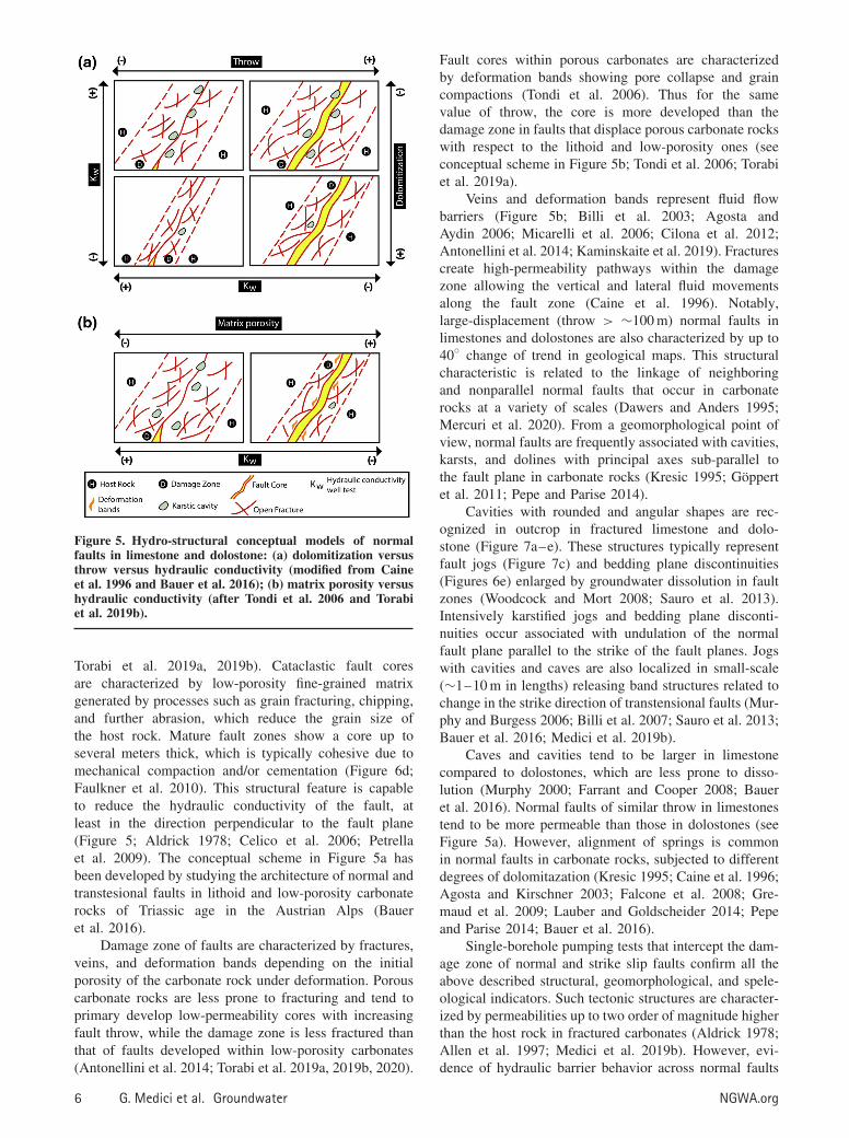
Figure 5. Hydro-structural conceptual models of normalfaults in limestone and dolostone: (a) dolomitization versusthrow versus hydraulic conductivity (modified from Caineet al. 1996 and Bauer et al. 2016); (b) matrix porosity versushydraulic conductivity (after Tondi et al. 2006 and Torabiet al. 2019b).
Torabi et al. 2019a, 2019b). Cataclastic fault coresare characterized by low-porosity fine-grained matrixgenerated by processes such as grain fracturing, chipping,and further abrasion, which reduce the grain size ofthe host rock. Mature fault zones show a core up toseveral meters thick, which is typically cohesive due tomechanical compaction and/or cementation (Figure 6d;Faulkner et al. 2010). This structural feature is capableto reduce the hydraulic conductivity of the fault, atleast in the direction perpendicular to the fault plane(Figure 5; Aldrick 1978; Celico et al. 2006; Petrellaet al. 2009). The conceptual scheme in Figure 5a hasbeen developed by studying the architecture of normal andtranstesional faults in lithoid and low-porosity carbonaterocks of Triassic age in the Austrian Alps (Baueret al. 2016).
Damage zone of faults are characterized by fractures,veins, and deformation bands depending on the initialporosity of the carbonate rock under deformation. Porouscarbonate rocks are less prone to fracturing and tend toprimary develop low-permeability cores with increasingfault throw, while the damage zone is less fractured thanthat of faults developed within low-porosity carbonates(Antonellini et al. 2014; Torabi et al. 2019a, 2019b, 2020).
Fault cores within porous carbonates are characterizedby deformation bands showing pore collapse and graincompactions (Tondi et al. 2006). Thus for the samevalue of throw, the core is more developed than thedamage zone in faults that displace porous carbonate rockswith respect to the lithoid and low-porosity ones (seeconceptual scheme in Figure 5b; Tondi et al. 2006; Torabiet al. 2019a).
Veins and deformation bands represent fluid flowbarriers (Figure 5b; Billi et al. 2003; Agosta andAydin 2006; Micarelli et al. 2006; Cilona et al. 2012;Antonellini et al. 2014; Kaminskaite et al. 2019). Fracturescreate high-permeability pathways within the damagezone allowing the vertical and lateral fluid movementsalong the fault zone (Caine et al. 1996). Notably,large-displacement (throw > ∼100 m) normal faults inlimestones and dolostones are also characterized by up to40◦ change of trend in geological maps. This structuralcharacteristic is related to the linkage of neighboringand nonparallel normal faults that occur in carbonaterocks at a variety of scales (Dawers and Anders 1995;Mercuri et al. 2020). From a geomorphological point ofview, normal faults are frequently associated with cavities,karsts, and dolines with principal axes sub-parallel tothe fault plane in carbonate rocks (Kresic 1995; Goppertet al. 2011; Pepe and Parise 2014).
Cavities with rounded and angular shapes are rec-ognized in outcrop in fractured limestone and dolo-stone (Figure 7a–e). These structures typically representfault jogs (Figure 7c) and bedding plane discontinuities(Figures 6e) enlarged by groundwater dissolution in faultzones (Woodcock and Mort 2008; Sauro et al. 2013).Intensively karstified jogs and bedding plane disconti-nuities occur associated with undulation of the normalfault plane parallel to the strike of the fault planes. Jogswith cavities and caves are also localized in small-scale(∼1–10 m in lengths) releasing band structures related tochange in the strike direction of transtensional faults (Mur-phy and Burgess 2006; Billi et al. 2007; Sauro et al. 2013;Bauer et al. 2016; Medici et al. 2019b).
Caves and cavities tend to be larger in limestonecompared to dolostones, which are less prone to disso-lution (Murphy 2000; Farrant and Cooper 2008; Baueret al. 2016). Normal faults of similar throw in limestonestend to be more permeable than those in dolostones (seeFigure 5a). However, alignment of springs is commonin normal faults in carbonate rocks, subjected to differentdegrees of dolomitazation (Kresic 1995; Caine et al. 1996;Agosta and Kirschner 2003; Falcone et al. 2008; Gre-maud et al. 2009; Lauber and Goldscheider 2014; Pepeand Parise 2014; Bauer et al. 2016).
Single-borehole pumping tests that intercept the dam-age zone of normal and strike slip faults confirm all theabove described structural, geomorphological, and spele-ological indicators. Such tectonic structures are character-ized by permeabilities up to two order of magnitude higherthan the host rock in fractured carbonates (Aldrick 1978;Allen et al. 1997; Medici et al. 2019b). However, evi-dence of hydraulic barrier behavior across normal faults
6 G. Medici et al. Groundwater NGWA.org

Figure 6. Normal faults: (a) map of Italy showing location of outcrops in (b) and (c); (b) fault in Mesozoic limestones showingthe fractured damage zone and the cataclastic fault core, Venere Fault (Central Apennines, Italy); (c) map of Spain showingthe location of the outcrop in (d); (d) the Basa Fault in southern Spain displacing carbonates of Miocene age; clay rich andcataclastic core and karstic conduits in the hanging wall block (interpretation from Torabi et al. 2020).
is more common in relatively high-displacement (throw> ∼100 m) faults due to presence of continuous, rela-tively thick, and low permeable cataclastic and clay-richfault cores (Figures 5a and 6b; Caine et al. 1996; Billiet al. 2003; Micarelli et al. 2006; Antonellini et al. 2008;Faulkner et al. 2010; Smeraglia et al. 2016a, 2016b;Ortiz et al. 2018; Torabi et al. 2019a, 2019b). Large-displacement normal faults in southern France and centralItaly displacing Meso-Cenozoic limestones compartmen-talize aquifers (Celico et al. 2006; Bucci et al. 2014).In fact, moving from the hanging wall to the footwallthe piezometric surface rapidly drops. The well test-scalehydraulic conductivity of these large-displacement nor-mal faults is reduced in the case of screens intercept-ing low-permeability cataclastic core (Figure 5b; Dausseet al. 2019).
Applications of Modeling ApproachesGroundwater flow and solute contaminant trans-
port occur at much higher rates along bedding planes,joints, and damage zone of low-porosity carbonates(Berkowitz 2002; Guo et al. 2019). Hence, the modelingstrategy must be arranged accounting for the structuralsetting, which controls the pattern of the rock discontinu-ities. A range of practical solutions is proposed below to
guide geo-modelers toward reliable representation of fluidflow in the subsurface in limestone and dolostone aquifers.Note that the proposed solutions refer to the three differentmethods used to model fluid flow in fractured and karstaquifers: (1) EPM, (2) CN, and (3) DFNs (see conceptualscheme in Figure 8).
Equivalent Porous MediumTectonic fractures typically show a principal orien-
tation in the hinterland of fold and thrust belts (e.g.,Figures 2 and 3) as well as in relatively undeformed areas(e.g., Figure 4). The dominant orientation of open frac-tures is sub-parallel to the axes of anticlines and synclinesin mountain ranges (Figure 3a; Carminati et al. 2010;Evans and Fischer 2012; Tavani et al. 2015). Joints arealso characterized in unfaulted areas by orthogonal sets ofhigh (70◦ –90◦) angle fractures with a more persistent set(Figure 4a–c; Odling et al. 1999; Gillespie et al. 2001;Billi 2005; Odonne et al. 2007). Rotation of grid (seeFigure 9a) axes allows assigning higher hydraulic conduc-tivity values in the direction of preferential orientation ofopen fractures in EPM flow models based on the Darcy’slaw. Note that, for details on coordinate transforms andparameters relative to the Darcy’s equation that describeslaminar flow in anisotropic media, the reader is referredto Harbaugh 2005.
NGWA.org G. Medici et al. Groundwater 7

Figure 7. Normal and strike-slip faults: (a) map of Great Britain with location of the outcrop in (b); (b) normal fault in thePermian Dolomitic Limestone of Leeds, Yorkshire (from Medici et al. 2019b); (c) detail of karstic cavity related to the normalfault in Leeds, Yorkshire; (d) map of Italy showing the location of studied outcrop in (e); (e) karstic cavities in the damagezone of strike-slip faults in the Miocene deposits of the Majella Massif, Fara San Martino, Central Italy.
A previous study found better calibration of steadystate models in Permian dolomitic limestones of GreatBritain by introducing a hydraulic conductivity two timeshigher in the direction of the dominant set of joints(Medici et al. 2019b). Other authors support the lattersolution used in the Permian dolomitic limestones ofGreat Britain in other carbonate aquifers arranged in eitherstratabound or nonstratabound joint system with a setof sub-vertical fractures that is dominant in the studiedoutcrops (Odling et al. 1999; Lemieux et al. 2006). Notethat, matching horizontal grid axis with the direction ofmaximum hydraulic conductivity brings a more detailedrepresentation of capture zones around abstraction wellsand plume dispersal when moving from groundwater flowto transport modeling (Pollock 1994; Berkowitz 2002).
By contrast, rotation of grids to introduce horizontalanisotropies is not adequate for normal faults (see
conceptual model Figure 9a and b). The direction ofsuch tectonic structures is less spatially consistent thanfold axis in thrust belts at the scale of a few to upto several kilometers. This structural pattern is relatedto linkage of non-subparallel normal faults (Soliva andBenedicto 2004; Mercuri et al. 2020). Similarly, normalfaults show variation of up to approximately 40◦ in theirtrends in areas where uplift-generated joints are mappedin fractured limestones (Gillespie et al. 2001). Hence,rotation of grids (Figure 9) must be defined with referenceto folds and uplift-related joints in the co-presence ofnormal faults.
Carbonate aquifers are primarily characterized byhigh conductive flow pathways in both faulted andunfaulted areas. In contrast, a range of high-angle(60◦ –90◦) centimeter to meter scale tectonic struc-tures such as cataclasites, veins, and deformation bands
8 G. Medici et al. Groundwater NGWA.org
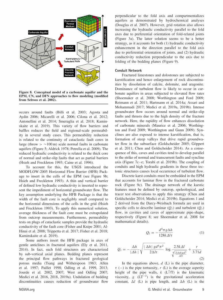
Figure 8. Conceptual model of a carbonate aquifer and theEPM, CN, and DFN approaches to flow modeling (modifiedfrom Selroos et al. 2002).
occurs around faults (Billi et al. 2003; Agosta andAydin 2006; Micarelli et al. 2006; Cilona et al. 2012;Antonellini et al. 2014; Smeraglia et al. 2018; Kamin-skaite et al. 2019). This variety of flow barriers andbaffles reduces the field and regional-scale permeabil-ity in several study cases. This permeability reductionis related to the continuity of cataclastic fault cores inlarge (throw > ∼100 m) scale normal faults in carbonateaquifers (Figure 5; Aldrick 1978; Petrella et al. 2009). Thereduced hydraulic conductivity is related to the thick coreof normal and strike-slip faults that act as partial barriers(Hsieh and Freckleton 1993; Caine et al. 1996).
To account for this, the USGS introduced theMODFLOW-2005 Horizontal Flow Barrier (HFB) Pack-age to insert in the cells of the EPM (see Figure 9b;Hsieh and Freckleton 1993). A thin and vertical barrierof defined low hydraulic conductivity is inserted to repre-sent the impediment of horizontal groundwater flow. Thekey assumption underlying the HFB Package is that thewidth of the fault core is negligibly small compared tothe horizontal dimensions of the cells in the grid (Hsiehand Freckleton 1993). To apply this numerical solution,average thickness of the fault core must be extrapolatedfrom outcrop measurements. Furthermore, permeabilitytests on plugs of cataclastic samples provide the hydraulicconductivity of the fault core (Fisher and Knipe 2001; Al-Hinai et al. 2008; Trippetta et al. 2017; Fisher et al. 2018;Kaminskaite et al. 2019).
Some authors insert the HFB package in axes ofgentle anticlines in fractured aquifers (Ely et al. 2011,2014). In fact, such fold structures are characterizedby sub-vertical axial planes. Bedding planes representthe principal flow pathways in fractured geologicalporous media (Tsang and Witherspoon 1983; Allenet al. 1997; Paillet 1998; Odling et al. 1999, 2013;Jourde et al. 2002, 2007; West and Odling 2007;Medici et al. 2016, 2018, 2019a). Undulation of beddingdiscontinuities causes reduction of groundwater flow
perpendicular to the fold axis and compartmentalizesaquifers as demonstrated by hydrochemical analyses(Douglas et al. 2007). However, grid rotation also allowsincreasing the hydraulic conductivity parallel to the foldaxes due to preferential orientation of fold-related joints(Figure 3a). The latter solution seems to be a betterstrategy, as it accounts for both (1) hydraulic conductivityenhancement in the direction parallel to the fold axisdue to preferential orientation of joints, and (2) hydraulicconductivity reduction perpendicular to the axis due tofolding of the bedding planes (Figure 9).
Conduit NetworkFractured limestones and dolostones are subjected to
karstification and hence enlargement of rock discontinu-ities by dissolution of calcite, dolomite, and aragonite.Dominance of turbulent flow is likely to occur in car-bonate aquifers in areas subjected to elevated flow rates(Shoemaker et al. 2008; Worthington and Ford 2009;Reimann et al. 2011; Hartmann et al. 2014a; Assari andMohammadi 2017; Medici et al. 2019a, 2019b). Intensegroundwater flow occurs around normal and strike-slipfaults and thrusts due to the high density of the fracturenetwork. Here, the rapidity of flow enhances dissolutionof carbonate minerals (Maurice et al. 2006; Worthing-ton and Ford 2009; Worthington and Gunn 2009). Syn-clines are also exposed to intense karstification, that is,formation of steep valleys that drive rapid groundwa-ter flow in the subsurface (Goldscheider 2005; Goppertet al. 2011; Chen and Goldscheider 2014). As a conse-quence of this, caves and cavities tend to develop parallelto the strike of normal and transcurrent faults and synclineaxis (Figure 7c–e; Torabi et al. 2019b). The coupling ofconduits and high hydraulic gradients in these three tec-tonic structures causes local occurrence of turbulent flow.
Discrete karst conduits must be embedded in the EPMthat accounts for laminar flow in the fractured carbonaterock (Figure 9c). The drainage network of the karsticfeatures must be defined by outcrop, speleological, andtracer test observations to apply this strategy (Chen andGoldscheider 2014; Medici et al. 2019b). Equations 1 and2 derived from the Darcy-Weisbach formula are used inspecific cells to describe laminar (Ql ) and turbulent (Qt )flow, in cavities and caves of approximate pipe-shape,respectively (Figure 8; see Shoemaker et al. 2008 formathematical details).
Ql = − d4πg�h
128kΔlτ(1)
Qt = − �h
|Δh |
√| �h| gd5π2
2�lτlog
2.5kΔl
4√
2|�h|gd3
Δlτ
+ r
3.71d
(2)In the equations above, d (L) is the pipe diameter,
τ (−) is the pipe tortuosity, r (L) is the average asperityheight of the pipe walls, k (L2/T) is the kinematicviscosity, g (LT−2) is the gravitational accelerationconstant, �l (L) is pipe length, and �h (L) is the
NGWA.org G. Medici et al. Groundwater 9

Figure 9. Groundwater flow in fractured carbonate aquifers; modeling strategy versus tectonic structure using the EPM andCN approaches: (a) grid rotation for, (b) Horizontal Flow Barrier for EPM, (c) Darcy-Weisbach equation for CN insertedinto an EPM.
hydraulic head loss along the pipe. A number of authorshave applied Equations 1 and 2 to MODFLOW-2005,who found the models are highly sensitive to thediameter (d ) of conduits (Shoemaker et al. 2008; Hillet al. 2010; Gallegos et al. 2013; Saller et al. 2013; Mediciet al. 2019b).
In summary, Equations 1 and 2 describe laminar andturbulent flow, respectively, in pipe conduits of a certaindiameter and surface roughness. Conduits elongatedparallel to the syncline axes have been described byspeleologists and geomorphologists as pipes of diametersin the range approximately 0.5–5 m (Murphy 2000; Fordand Williams 2013). Springs have been found in karstenvironments connected to pipe-shaped caves in the Alpsin France, Switzerland, Austria, and Germany, in theAppennines in Italy and in the Woodville karst plain inFlorida (Figure 2a; Kiraly 1975; Falcone et al. 2008, 2012;Shoemaker et al. 2008; Goldscheider and Drew 2014).The Darcy-Weisbach equations have been incorporatedby the United States Geological Survey (USGS) inthe Conduit Flow Process Mode-1 (CFPM-1) Packageof MODFLOW-2005 to model flow in such pipe-shape conduits and represent carbonate aquifers as dualporosity media (Shoemaker et al. 2008; Hill et al.2010).
The CFPM-1 modeling solution is used to account forthe preferential-flow pathway behavior of normal faultsat a range of scales in carbonate aquifers (Figure 9c;Hsieh and Freckleton 1993; Caine et al. 1996; Shoemakeret al. 2008; Faulkner et al. 2010; Hill et al. 2010;Bense et al. 2013). More in detail, flow through pipes,which is described by Equations 1 and 2, is insertedin specific fault segments, which are characterized byalignment of springs, dolines and caves. However, thismodeling solution must be coupled with the HFB Packageto also account for the barrier behavior of large (throw >
∼100 m) scale normal faults.The HFB Package is inserted in portions of the
model domain that are characterized by sharp drops ofthe piezometric surface moving from the hanging wall tothe footwall blocks to account for the across-strike barrierbehavior of normal faults (Hsieh and Freckleton 1993;Mohamed and Worden 2006; Chaussard et al. 2014;Hanson et al. 2014). A valid and alternative methodproposed by the USGS to model turbulent flow is theConduit Flow Process Mode-2 (CFPM-2). This solutionconsists of representing turbulence in a network oflarge pores with a specific average diameter (Shoemakeret al. 2008; Reimann and Hill 2009; Reimann et al. 2011;Xu et al. 2015). In the latter method that is mathematically
10 G. Medici et al. Groundwater NGWA.org

described in detail in Reimann et al. (2011), the flowvelocity under laminar and turbulent flow conditions isdescribed by the Equation 3.
V = Re
dk(3)
where Re is the Reynolds number, d (L) is the meanvoid diameter, and k (L2/T) is the kinematic viscosityof water. Users only need to assign upper and lowerRe, the mean groundwater temperature for computingviscosity, and mean void diameters. Hence, this numericalmethodology does not require a detailed geometricaldefinition of the CNs and can be coupled with the CFPM-1accounting for turbulence both in discrete conduits and inthe interbedded matrix. Consequently, CFPM-2 has beenused to describe turbulent flow in fractured limestones ina number of numerical models. Despite this, we retain, inagreement with the developers of the conduit flow process(see Shoemaker et al. 2008), that this strategy is moreappropriate to represent turbulence in carbonate rocks withpaleobiogenic origin such as tufa and travertine. In thesekind of carbonate rocks, a network of large and connectedpores of sedimentary origin is effectively present (Loveand Chafetz 1988; Guo and Riding 1994). The CFPM-2 is inserted in specific layers that are characterized bylarge pores, where turbulent flow occurs. Other layers thatcorrespond to parts of the stratigraphic succession withsmaller voids are instead modeled using laminar/Darcianflow in the EPM (Shoemaker et al. 2008; Reimannet al. 2011). In the case of travertine or tufa and theoccurrence of a valley where intense groundwater flowand karst conduits occur; the CFPM-1 and CFPM-2approaches can be combined in the 3D domain to modelturbulence in pipe-shaped conduits and large pores ofsedimentary origin, respectively (Shoemaker et al. 2008).
Discrete Fracture NetworkDFN modeling generates distributions of fractures
and bedding planes and compares these discontinuitieswith observed data from outcrop scanline and/or boreholeacoustic televiewer logging to represent their position,size, and mechanical aperture (Parker et al. 2019). TheseDFN models can be generated either from a combinationof outcrop mapping, borehole data, and seismic data (e.g.,Kattenhorn and Pollard 2001; Cvetkovic et al. 2004; Panzaet al. 2015; Zambrano et al. 2016; Giuffrida et al. 2020),or from using a stochastic approach in case of limiteddata availability (e.g., Voeckler and Allen 2012; Hymanet al. 2015; Lei et al. 2017; Lepillier et al. 2020).Mechanical stratigraphy plays an important role in thefracture network geometry as well as in the resultantgroundwater flow (e.g., Cooke et al. 2006). Therefore,capturing the heterogeneities and variations in mechanicallayering is of paramount importance when generatingDFN models. Combination of suitable algorithms andavailability of data will lead to a more realistic modeledfracture distribution in carbonate aquifers. In fact, thefracture data from outcrops, alone, cannot adequately
represent the complexity of geological structures in thesubsurface. Lemieux et al. (2006) combined outcrop andcore data to generate a realistic DFN model at a smallscale (∼100 m in lengths) in a dolostone of Silurianage in Ontario. However, the use of seismic data canlead to a larger scale (∼101 m in lengths) and a deeper(∼102 –103 meters below the ground level) representationof the DFN, as the 3D fracturing network can also begeophysically generated by combining fracture data fromacoustic televiewer logging with seismic attributes. In thisapproach, the scale gap between the dataset from wells isbridged by the use of seismic data in sedimentary rocks(Botter et al. 2017a, 2017b). Recently, seismic data ofthe Cretaceous carbonates in the Danish North Sea hasbeen utilized to characterize the fracture network for flowmodeling applications (Aabø et al. 2020).
In contrary to EPM approach, DFN models aresupported by unstructured grids and do not requirerotating grids to represent the flow properties in thepresence of a dominant set of sub-vertical joints. Thegenerated fracture sets are then added into a flow model(e.g., MAFIC, ConnectiveFlow, dfnWorks, DFNFlow,HGS, CRAK, and SMOKER) to derive estimates of thebedrock hydraulic conductivity (Neuman 2005; Rutqvistet al. 2013; Hyman et al. 2015). Rock discontinuitiesare assumed permeable as supported by well-testing dataand must be assigned a hydraulic aperture to providea fracture transmissivity in the carbonate rock mass(Selroos et al. 2002; Parker et al. 2019). The use ofseismic data to map the fracture hydraulic propertiesat depth (e.g., effective fracture porosity and hydraulicconductivity) can also lower uncertainties associated withthe properties of rocks located away from the wells (e.g.,Parra et al. 2006; Parra and Emery 2013). Recent advancesin DFN groundwater flow and transport modeling coupleadvective flow through the fractures with diffusivityin the matrix blocks (Parker et al. 2019). In theirworkflow, Parker et al. (2019) couple DFN and EPMapproaches using the FRACTRAN numerical code leadingto match model outputs with information from wells onthe dispersal of monitored plumes at industrial field sites.The latter approach contrasts a number of researches(e.g., Benke and Painter 2003; Voeckler and Allen 2012;Hyman et al. 2015) that neglect diffusion in the matrixthat increases the computational efforts.
DiscussionWe presented the strategies for modeling groundwater
flow in the presence of different tectonic structureswith regards to the three approaches, EPM, CFPM-1, 2, and DFN, used to model groundwater flow andcontaminant transport in carbonate aquifers (Figure 8;Selroos et al. 2002; Shoemaker et al. 2008). The choiceof modeling approach primarily depends on interplaysbetween the observation scale, degree of karstification,hydraulic behavior (barrier vs. conduit), and orientationof the rock discontinuities. The easiest numerical solutionin terms of computational efforts is represented by the
NGWA.org G. Medici et al. Groundwater 11

exclusive Darcian flow in an EPM (Chapman et al. 2013).This choice is considered reasonable when observationsat the outcrop scale match structural maps in terms oforientation of the rock discontinuities (Odling et al. 1999;Lemieux et al. 2006). In the latter case of consistentorientation of fractures from outcrop up to groundwaterflow model scale, one horizontal grid axis can beoriented parallel to the Fisher mean vector of high anglefold-related fractures measured in outcrops. However, acombination of two or three approaches is needed tomodel fluid flow in a variety of case studies to representthe complexity of carbonate aquifers.
Groundwater flow models at the scale of multi-ple industrial plants (∼0.5–10 km) and single water-sheds (∼0.1–100 km) use conduits embedded within anEPM approach at relatively shallow (<∼0.1 km) depths(Figure 9c; Gallegos et al. 2013; Chen and Goldschei-der 2014; Saller et al. 2013; Medici et al. 2019b). How-ever, groundwater flow models only account for a CNapproach in some case studies in fold and thrust belts. Insuch cases, elevated hydraulic gradients are responsiblefor a high degree of karstification and flow is largely dom-inated by cavities that are a few meters wide. Turbulentflow occurs in carbonate aquifers under such hydrogeo-logical conditions (Hill et al. 2010).
DFN models are used to represent groundwater flowat the scale of the industrial field site to predict thedispersal of plumes in approximately 0.3–5 km lengthin less intensively karstified carbonate aquifers (Chapmanand Parker 2005; Parker et al. 2008; Cheong et al. 2017).The availability of wells in a relatively small area coupledwith 1D scanline measurements allows the network ofbedding plane discontinuities and fractures to be definedin three dimensions at high resolution. At the scale ofan industrial site (∼0.3–5 km), recent applications in thefractured Silurian Dolostone of Ontario allow the couplingof a DFN with an EPM approach to simulate advectiveand diffusive flow in fractures and the matrix, respectively(Parker et al. 2019). Here, karstic features were notdetected by acoustic and televiewer logging due to thechoice of neglecting the CN approach. The combinationof a DFN with an EPM approach applied to the SilurianDolostone of Ontario is called DFN-M. This approachhas been successful in matching experimental data onthe spatial distribution of a monitored groundwater plumewith a contaminant transport model.
However, a future research scenario could involvecombining the CN with a DFN approach to model fluidflow in lithoid carbonate aquifers. Indeed, cavities ofdiameters of a few centimeters are present in carbon-ate aquifers even in areas characterized by relatively lowhydraulic gradients, flat topography, and sub-horizontalbeds where the stratigraphic succession is faulted (Mur-phy 2000; Medici et al. 2019b). The coupling of a DFNwith a CN approach can also have an impact on model-ing flow at much higher depths (∼1–3 km) in medium-and high-enthalpy geothermal reservoirs. Paleokarst fea-tures in bedding plane discontinuities and sub-verticaljoints were detected at these greater depths significantly
influencing the recovery of production wells (Bauer andToth 2017). A DFN must be coupled to a CN to rep-resent fluid flow in marine carbonate rocks that havebeen exposed to episodes of emersion and erosion, andhence to the development of paleokarst cavities (Vecseiand Sanders 1997; Brandano 2017). The combination ofa DFN and a CN approach can be beneficial to either thechemical industry for managing the contaminant plume orthe geothermal energy sector.
However, maximum complexity in terms of computa-tion efforts may be necessary to model fluid flow in deepaquifers exploited to recover hot water mixed with vaporin porous carbonates. In this case, the EPM approachmust be used, and the 3D domain should be divided byhydrofacies to account for the significant flow componentoccurring within the matrix. Residual fracture and channelflow in paleokarst conduits occurs under pumping condi-tions and hence the discrete fracture and CNs need to beinserted to the 3D models (Bauer and Toth 2017; Mediciet al. 2018; Tomassetti et al. 2018).
ConclusionsGroundwater flow is challenging to model in car-
bonate aquifers due to interplays between brittle tectonicstructures and karstification. Fluid flow is controlled byrock discontinuities, which are represented by beddingplane and tectonic fractures in shallow carbonate aquifersacross the world. Consequently, modeling strategies mustbe reviewed in relation to the pattern of rock discontinu-ity as well as the degree of karstification using the threedifferent existing approaches (EPM, CN, and DFN) devel-oped to model groundwater flow in porous and fracturedrocks. The findings of our review can be summarized infour key points:
1. Rotating the grids using an EPM approach is recom-mended for mountain belt settings to account for higherhydraulic conductivity parallel to the fold axis fromthe scale of a few up to tens of kilometers. The samestrategy is appropriate to model fluid flow in unfaultedareas using an EPM approach in jointed and highlyhorizontally anisotropic carbonate aquifers. In thesegeological media, sub-vertical joints are characterizedby a dominant set according to discontinuity surveysundertaken in quarries and cliffs across Europe andnorthern America.
2. Rapid groundwater flow and karstification occurs insynclines, normal faults, and thrusts in limestone anddolostone aquifers. Systems of caves and cavitiesoccur and groundwater flow models need to belocally modified to represent turbulence. Hence, a CNapproach is needed to insert channels characterized byturbulent flow embedded in an EPM.
3. The DFN approach is supported by unstructured gridsenabling 3D representation of fractures contributingto fluid flow. This approach is used at the scale ofthe 0.3–5 km in less heavily kartsified aquifers andhas been recently combined with an EPM approach to
12 G. Medici et al. Groundwater NGWA.org

simulate contaminant transport in the low conductivematrix.
4. Combining an EPM method with DFN and CNmethods represents a future research approach thatis not currently practiced in hydrogeology. The EPMmethod is needed in porous carbonate rocks in deepaquifers due to the significant component of matrixflow. However, discrete fractures and conduits stillinfluence flow to pumped wells in medium and highenthalpy geothermal reservoirs and need therefore tobe inserted in the 3D domain.
Overall, networks of fractures and karst conduitshighly control groundwater flow in carbonate aquifersand major groundwater resources are here stored. Hence,specific guidelines are needed in faulted and unfaultedareas to better represent fluid flow in these geologicalmedia combining the three existing methodologies: EPM,CN, and DFN.
AcknowledgmentsThe research is a synthesis of hydrogeological stud-
ies, structural geological surveys, and field trips under-taken across Europe (in Ireland, Great Britain, Italy, andSpain) and northern America. Critical discussions withBeth Parker (University of Guelph), Andrea Billi (CNR-IGAG), Girolamo Belardi (CNR-IGAG), Eugenio Carmi-nati, Marco Brandano, and Carlo Doglioni (Sapienza Uni-versity of Rome) on development of fractures and stylo-lites in carbonate rocks are appreciated. This research alsobenefitted from discussion with Quentin Fisher (Univer-sity of Leeds) and Gerard Massonnat (TotalE&P) on thehydraulic behavior of deformation bands and rock joints.Permeability tests on fault rock samples in the WolfsonMultiphase Laboratory of the University of Leeds werealso instructive for this review. Rebecca Nicole Gustine,Michael Frederick Meyer, Steven Kent Overleft, and theProfessional Editing Service of the Washington State Uni-versity have kindly reviewed the language. We are gratefulto the Executive Editor Thomas Missimer (Florida GulfCoast University), Associate Editor Scott James (BaylorUniversity), and an anonymous reviewer for the construc-tive review comments.
ReferencesAabø, T.M., J.S. Dramsch, C.L. Wurtzen, S. Seyum, and
M. Welch. 2020. An integrated workflow for fracturecharacterization in chalk reservoirs, applied to the KrakaField. Marine and Petroleum Geology 112: 104065.
Agosta, F., M. Alessandroni, M. Antonellini, E. Tondi, andM. Giorgioni. 2010. From fractures to flow: A field-basedquantitative analysis of an outcropping carbonate reservoir.Tectonophysics 490: 197–213.
Agosta, F., and A. Aydin. 2006. Architecture and deformationmechanism of a basin-bounding normal fault in Mesozoicplatform carbonates, central Italy. Journal of StructuralGeology 28, no. 8: 1445–1467.
Agosta, F., and D.L. Kirschner. 2003. Fluid conduits incarbonate-hosted seismogenic normal faults of central Italy.
Journal of Geophysical Research: Solid Earth 108, no. B4.https://doi.org/10.1029/2002JB002013
Al-Hinai, S., Q.J. Fisher, B. Al-Busafi, P. Guise, and C.A.Grattoni. 2008. Laboratory measurements of the relativepermeability of cataclastic fault rocks: An importantconsideration for production simulation modelling. Marineand Petroleum Geology 25, no. 6: 473–485.
Aldrick, R.J. 1978. The hydrogeology of the magnesianlimestones in Yorkshire between the River Wharfe and theRiver Aire. Quarterly Journal of Engineering Geology andHydrogeology 11, no. 2: 193–201.
Allen, D.J., L.M. Brewerton, B.R. Colebee, M.A. Gibbs,A. Lewis, S.J. MacDonald, A.T. Wagstaff, and L.J.Williams. 1997. The Physical Properties of Major Aquifersin England and Wales . Technical Report WD/97/34, 157-287. Nottingham, UK: British Geological Survey.
Allmendinger, R.W. 1998. Inverse and forward numericalmodeling of trishear fault-propagation folds. Tectonics 17,no. 4: 640–656.
Amraoui, F., M. Razack, and L. Bouchaou. 2003. Turbiditydynamics in karstic systems. Example of Ribaa and Bittitsprings in the Middle Atlas (Morocco). HydrologicalSciences Journal 48, no. 6: 971–984.
Amoruso, A., L. Crescentini, M. Petitta, and M. Tallini. 2013.Parsimonious recharge/discharge modeling in carbonatefractured aquifers: The groundwater flow in the Gran Sassoaquifer (central Italy). Journal of Hydrology 476: 136–146.
Angelini, P., and W. Dragoni. 1997. The problem of modelinglimestone springs: The case of Bagnara (North Apennines,Italy). Groundwater 35, no. 4: 612–618.
Antonellini, M., L. Petracchini, A. Billi, and D. Scrocca.2014. First reported occurrence of deformation bands ina platform limestone, the Jurassic Calcare Massiccio Fm.,northern Apennines, Italy. Tectonophysics 628: 85–104.
Antonellini, M., E. Tondi, F. Agosta, A. Aydin, and G. Cello.2008. Failure modes in deep-water carbonates and theirimpact for fault development: Majella Mountain, CentralApennines, Italy. Marine and Petroleum Geology 25, no.10: 1074–1096.
Assari, A., and Z. Mohammadi. 2017. Assessing flow pathsin a karst aquifer based on multiple dye tracing testsusing stochastic simulation and the MODFLOW-CFP code.Hydrogeology Journal 25, no. 6: 1679–1702.
Aydin, A. 2000. Fractures, faults, and hydrocarbon entrapment,migration and flow. Marine and Petroleum Geology 17, no.7: 797–814.
Bakalowicz, M. 2015. Karst and karst groundwater resources inthe Mediterranean. Environmental Earth Sciences 74, no.1: 5–14.
Bales, R.C., C.P. Gerba, G.H. Grondin, and J.L. Jensen.1989. Bacteriophage transport in sandy soil and fracturedtuff. Applied and Environmental Microbiology 55, no. 8:2061–2067.
Barrash, W., and M.E. Dougherty. 1997. Modeling axiallysymmetric and nonsymmetric flow to a well with MOD-FLOW, and application to Goddard2 well test, Boise, Idaho.Groundwater 35, no. 4: 602–611.
Bauer, M., and T.M. Toth. 2017. Characterization and DFNmodelling of the fracture network in a Mesozoic karst reser-voir: Gomba oilfield, Paleogene Basin, Central Hungary.Journal of Petroleum Geology 40, no. 3: 319–334.
Bauer, H., T.C. Schrockenfuchs, and K. Decker. 2016. Hydroge-ological properties of fault zones in a karstified carbonateaquifer (Northern Calcareous Alps, Austria). HydrogeologyJournal 24: 1147–1170.
Bauer, S., R. Liedl, and M. Sauter. 2003. Modeling ofkarst aquifer genesis: Influence of exchange flow.Water Resources Research 39, no. 10. https://agupubs.onlinelibrary.wiley.com/doi/full/10.1029/2003WR002218
Benke, R., and S. Painter. 2003. Modeling conservative tracertransport in fracture networks with a hybrid approach based
NGWA.org G. Medici et al. Groundwater 13

on the Boltzmann transport equation. Water ResourcesResearch 39, no. 11. https://agupubs.onlinelibrary.wiley.com/doi/full/10.1029/2003WR001966
Bense, V.F., T. Gleeson, S.E. Loveless, O. Bour, and J. Scibek.2013. Fault zone hydrogeology. Earth-Science Reviews127: 171–192.
Berkowitz, B. 2002. Characterizing flow and transport infractured geological media: A review. Advances in WaterResources 25: 861–884.
Bidaux, P., and C. Drogue. 1993. Calculation of low-rangeflow velocities in fractured carbonate media from boreholehydrochemical logging data comparison with thermometricresults. Groundwater 31: 19–26.
Billi, A., A. Valle, M. Brilli, C. Faccenna, and R. Funiciello.2007. Fracture-controlled fluid circulation and dissolutionalweathering in sinkhole-prone carbonate rocks from centralItaly. Journal of Structural Geology 29, no. 3: 385–395.
Billi, A. 2005. Attributes and influence on fluid flow offractures in foreland carbonates of southern Italy. Journalof Structural Geology 27: 1630–1643.
Billi, A., F. Salvini, and F. Storti. 2003. The damage zone-faultcore transition in carbonate rocks: Implications for faultgrowth, structure and permeability. Journal of StructuralGeology 25, no. 11: 1779–1794.
Boni, C., P. Bono, and G. Capelli. 1986. Schema idrogeolog-ical dell’Italia centrale. Memorie della Societa GeologicaItaliana 35: 991–1012.
Borovic, S., J. Terzic, and M. Pola. 2019. Groundwater qualityon the adriatic karst Island of Mljet (Croatia) and itsimplications on water supply. Geofluids 20: 1–14. https://doi.org/10.1155/2019/5142712
Boyer, S.E., and D. Elliot. 1982. Thrust systems. AAPG Bulletin66, no. 9: 1196–1230.
Botter, C., N. Cardozo, I. Lecomte, A. Rotevatn, and G. Paton.2017a. The impact of faults and fluid flow on seismicimages of a relay ramp over production time. PetroleumGeoscience 23: 17–28.
Botter, C., N. Cardozo, D. Qu, J. Tveranger, and D. Kolyukhin.2017b. Seismic characterization of fault facies models.Interpretation 5: SP9–SP26.
Brandano, M. 2017. Unravelling the origin of a Paleogeneunconformity in the Latium-Abruzzi carbonate succession:A shaved platform. Palaeogeography, Palaeoclimatology,Palaeoecology 485: 687–696.
Bucci, A., E. Petrella, G. Naclerio, S. Gambatese, and F. Celico.2014. Bacterial migration through low-permeability faultzones in compartmentalised aquifer systems: A case studyin southern Italy. International Journal of Speleology 43,no. 3: 273–281.
Caine, J.S., J.P. Evans, and C.B. Forster. 1996. Fault zonearchitecture and permeability structure. Geology 24, no. 11:1025–1028.
Carminati, E., D. Scrocca, and C. Doglioni. 2010. Compaction-induced stress variations with depth in an active anti-cline: Northern Apennines, Italy. Journal of GeophysicalResearch: Solid Earth 115, no. B2. https://doi.org/10.1029/2009JB006395
Carminati, E., M. Cuffaro, and C. Doglioni. 2009. Cenozoicuplift of Europe. Tectonics 28, no. 4. https://doi.org/10.1029/2009TC002472
Celico, F., E. Petrella, and P. Celico. 2006. Hydrogeologicalbehaviour of some fault zones in a carbonate aquifer ofsouthern Italy: An experimentally based model. Terra Nova18, no. 5: 308–313.
Chapman, S.W., B.L. Parker, J.A. Cherry, S.D. McDonald, K.J.Goldstein, J.J. Frederick, D.J.S. Germain, D.M. Cutt, andC.E. Williams. 2013. Combined MODFLOW-FRACTRANapplication to assess chlorinated solvent transport andremediation in fractured sedimentary rock. RemediationJournal 23, no. 3: 7–35.
Chapman, S.W., and B.L. Parker. 2005. Plume persistencedue to aquitard back diffusion following dense non-aqueous phase liquid source removal or isolation. WaterResources Research 41, no. 12. https://doi.org/10.1029/2005WR004224
Chaussard, E., R. Burgmann, M. Shirzaei, E.J. Fielding, and B.L.Baker. 2014. Predictability of hydraulic head changes andcharacterization of aquifer-system and fault properties fromInSAR-derived ground deformation. Journal of Geophysi-cal Research: Solid Earth 119, no. 8: 6572–6590.
Cheong, J.Y., S.Y. Hamm, D.H. Lim, and S.G. Kim. 2017.Hydraulic parameter generation technique using a discretefracture network with bedrock heterogeneity in Korea.Water 9, no. 12. https://doi.org/10.3390/w9120937
Chen, Z., and N. Goldscheider. 2014. Modeling spatially andtemporally varied hydraulic behavior of a folded karstsystem with dominant conduit drainage at catchment scale,Hochifen–Gottesacker, Alps. Journal of Hydrology 514:41–52.
Cilona, A., P. Baud, E. Tondi, F. Agosta, S. Vinciguerra,A. Rustichelli, and C.J. Spiers. 2012. Deformation bandsin porous carbonate grainstones: Field and laboratoryobservations. Journal of Structural Geology 45: 137–157.
Cooke, M.L., J.A. Simo, C.A. Underwood, and P. Rijken.2006. Mechanical stratigraphic controls on fracture patternswithin carbonates and implications for groundwater flow.Sedimentary Geology 184: 225–239.
Cosentino, D., P. Cipollari, P. Marsili, and D. Scrocca. 2010.Geology of the central Apennines: A regional review.Journal of the Virtual Explorer 36, no. 11: 1–37.
Cvetkovic, V., S. Painter, N. Outters, and J.O. Selroos.2004. Stochastic simulation of radionuclide migrationin discretely fractured rock near the Aspo Hard RockLaboratory. Water Resources Research 40, no. 2. https://doi.org/10.1029/2003WR002655
Dausse, A., V. Leonardi, and H. Jourde. 2019. Hydraulic char-acterization and identification of flow-bearing structuresbased on multi-scale investigations applied to the Lez karstaquifer. Journal of Hydrology Regional Studies 26: 100627.
Dawers, N.H., and M.H. Anders. 1995. Displacement-lengthscaling and fault linkage. Journal of Structural Geology 17,no. 5: 607–614.
Douglas, A.A., L.J. Osiensky, and C.K. Keller. 2007. Carbon-14dating of ground water in the Palouse Basin of the ColumbiaRiver basalts. Journal of Hydrology 334: 502–512.
Ely, D.M., E.R. Burns, D.S. Morgan, J.J. Vaccaro. 2014.Numerical simulation of groundwater flow in the ColumbiaPlateau Regional Aquifer System, Idaho, Oregon, andWashington. U.S. Geological Survey Report 5127, 90.
Ely, D.M., M.P. Bachmann, and J.J. Vaccaro. 2011. NumericalSimulation of Groundwater Flow for the Yakima River BasinAquifer System . Washington, DC: U.S. Geological Survey.
Evans, M.A., and M.P. Fischer. 2012. On the distributionof fluids in folds: A review of controlling factors andprocesses. Journal of Structural Geology 44: 2–24.
Falcone, A.R., V. Carucci, A. Falgiani, M. Manetta, B. Parisse,M. Petitta, S. Rusi, M. Spizzico, and M. Tallini. 2012.Changes on groundwater flow and hydrochemistry ofthe Gran Sasso carbonate aquifer after 2009 l’Aquilaearthquake. International Journal of Geosciences 131, no.3: 450–474.
Falcone, R.A., A. Falgiani, B. Parisse, M. Petitta, M. Spizzico,and M. Tallini. 2008. Chemical and isotopic (δ18O‰,δ2H‰, δ13C‰, 222Rn) multi-tracing for groundwater con-ceptual model of carbonate aquifer (Gran Sasso INFNunderground laboratory—central Italy). Journal of Hydrol-ogy 357: 368–388.
Farrant, A.R., and A.H. Cooper. 2008. Karst geohazards in theUK: The use of digital data for hazard management. Quar-terly Journal of Engineering Geology and Hydrogeology 41,no. 3: 339–356.
14 G. Medici et al. Groundwater NGWA.org

Faulkner, D.R., C.A.L. Jackson, R.J. Lunn, R.W. Schlische, Z.K.Shipton, C.A.J. Wibberley, and M.O. Withjack. 2010. Areview of recent developments concerning the structure,mechanics and fluid flow properties of fault zones. Journalof Structural Geology 32, no. 11: 1557–1575.
Fiorillo, F., M. Petitta, E. Preziosi, S. Rusi, L. Espos-ito, and M. Tallini. 2015. Long-term trend and fluctua-tions of karst spring discharge in a Mediterranean area(central-southern Italy). Environmental Earth Sciences 74:153–172.
Fisher, Q.J., J. Haneef, C.A. Grattoni, S. Allshorn, and P. Lor-inczi. 2018. Permeability of fault rocks in siliciclastic reser-voirs: Recent advances. Marine and Petroleum Geology 91:29–42.
Fisher, Q.J., and R.J. Knipe. 2001. The permeability of faultswithin siliciclastic petroleum reservoirs of the North Seaand Norwegian Continental Shelf. Marine and PetroleumGeology 18, no. 10: 1063–1081.
Flugel, E. 2013. Microfacies of Carbonate Rocks: Analysis,Interpretation and Application . Berlin, Germany: SpringerScience & Business Media.
Ford, D., and P.D. Williams. 2013. Karst Hydrogeology andGeomorphology . New York: John Wiley & Sons.
Gallegos, J.J., B.X. Hu, and H. Davis. 2013. Simulating flowin karst aquifers at laboratory and sub-regional scalesusing MODFLOW-CFP. Hydrogeology Journal 21, no. 8:1749–1760.
Ghasemizadeh, R., F. Hellweger, C. Butscher, I. Padilla,D. Vesper, M. Field, and A. Alshawabkeh. 2012. Review:Groundwater flow and transport modeling of karst aquifers,with particular reference to the North Coast Limestoneaquifer system of Puerto Rico. Hydrogeology Journal 20,no. 8: 1441–1461.
Giacopetti, M., M. Materazzi, G. Pambianchi, and K. Posavec.2017. Analysis of mountain springs discharge time series inthe Tennacola stream catchment (Central Apennine, Italy).Environmental Earth Sciences 76, no. 1: 20–31.
Gillespie, P.A., J.J. Walsh, J. Watterson, C.G. Bonson, andT. Manzocchi. 2001. Scaling relationships of joint and veinarrays from The Burren, Co. Clare, Ireland. Journal ofStructural Geology 23: 183–201.
Giuffrida, A., F. Agosta, A. Rustichelli, E. Panza, V. La Bruna,M. Eriksson, S. Torrieri, and M. Giorgioni. 2020. Fracturestratigraphy and DFN modelling of tight carbonates, thecase study of the lower cretaceous carbonates exposed atthe Monte Alpi (Basilicata, Italy). Marine and PetroleumGeology 112: 104045.
Goldscheider, N. 2012. A holistic approach to groundwaterprotection and ecosystem services in karst terrains. AQUAMundi 3, no. 2: 117–124.
Goldscheider, N., and D. Drew. 2014. Methods in Karst Hydro-geology: IAH: International Contributions to Hydrogeol-ogy . Boca Raton, Florida: CRC Press.
Goldscheider, N., J. Madl-Szonyi, A. Eross, and E. Schill.2010. Review: Thermal water resources in carbonate rockaquifers. Hydrogeology Journal 18, no. 6: 1303–1318.
Goldscheider, N. 2005. Fold structure and underground drainagepattern in the alpine karst system Hochifen-Gottesacker.Eclogae Geologicae Helvetiae 98: 1–17.
Goppert, N., N. Goldscheider, and H. Scholz. 2011. Karstgeomorphology of carbonatic conglomerates in the foldedMolasse zone of the Northern Alps (Austria/Germany).Geomorphology 130: 289–298.
Goppert, N., and N. Goldscheider. 2008. Solute and colloidtransport in karst conduits under low-and high-flow con-ditions. Groundwater 46: 61–68.
Gremaud, V., N. Goldscheider, L. Savoy, G. Favre, andH. Masson. 2009. Geological structure, recharge processesand underground drainage of a glacierised karst aquifersystem, Tsanfleuron-Sanetsch, Swiss Alps. HydrogeologyJournal 17, no. 8: 1833–1848.
Guo, Z., G.E. Fogg, M.L. Brusseau, E.M. LaBolle, and J. Lopez.2019. Modeling groundwater contaminant transport in thepresence of large heterogeneity: A case study comparingMT3D and RWhet. Hydrogeology Journal 27, no. 4:1363–1371.
Guo, F., G. Jiang, D. Yuan, and J.S. Polk. 2013. Evolution ofmajor environmental geological problems in karst areas ofsouthwestern China. Environmental Earth Sciences 69, no.7: 2427–2435.
Guo, L., and R. Riding. 1994. Origin and diagenesis of qua-ternary travertine shrub fabrics, Rapolano Terme, CentralItaly. Sedimentology 41, no. 3: 499–520.
Hanson, R.T., E.F. Lorraine, C. Claudia, C. Faunt, D.R. Gibbs,and W. Schmid. 2014. Hydrologic models and analysis ofwater availability in Cuyama Valley, California. No. 2014-5150. U.S. Geological Survey, Scientific InvestigationsReport 2014-5150.
Harbaugh A.W. 2005. MODFLOW-2005, the U.S. GeologicalSurvey modular ground-water model—The ground-waterflow process. U.S. Geological Survey, Techiniques andMethods Report 6-A16.
Hartmann, A., and A. Baker. 2017. Modeling karst vadose zonehydrology and its relevance for palaeoclimate reconstruc-tion. Earth Science Reviews 172: 178–192.
Hartmann, A., N. Goldscheider, T. Wagener, J. Lange, andM. Weiler. 2014a. Karst water resources in a changingworld: Review of hydrological modeling approaches.Reviews of Geophysics 52, no. 3: 218–242.
Hartmann, A., M. Mudarra, B. Andreo, A. Marın, T. Wagener,and J. Lange. 2014b. Modeling spatiotemporal impactsof hydroclimatic extremes on groundwater recharge at aMediterranean karst aquifer. Water Resources Research 50,no. 8: 6507–6521.
Hartmann, S., N.E. Odling, and L.J. West. 2007. A multi-directional tracer test in the fractured chalk aquifer ofE. Yorkshire, UK. Journal of Contaminant Hydrology 94:315–331.
Hill, M.E., M.T. Stewart, and A. Martin. 2010. Evaluation ofthe MODFLOW-2005 conduit flow process. Groundwater48, no. 4: 549–559.
Hyman, J.D., S. Karra, N. Makedonska, C.W. Gable, S.L.Painter, and H.S. Viswanathan. 2015. dfnWorks: A discretefracture network framework for modeling subsurface flowand transport. Computational Geosciences 84: 10–19.
Hsieh, P.A., and J.R. Freckleton. 1993. Documentation of a com-puter program to simulate horizontal-flow barriers usingthe U.S. Geological Survey’s modular three-dimensionalfinite-difference ground-water flow model. U.S. GeologicalSurvey, Open-File Report 92-477.
Jolivet, L., and C. Faccenna. 2000. Mediterranean extensionand the Africa-Eurasia collision. Tectonics 19, no. 6:1095–1106.
Jourde, H., P. Fenart, M. Vinches, S. Pistre, and B. Vayssade.2007. Relationship between the geometrical and structuralproperties of layered fractured rocks and their effective per-meability tensor. A simulation study. Journal of Hydrology337: 117–132.
Jourde, H., S. Pistre, P. Perrochet, and C. Drogue. 2002. Originof fractional flow dimension to a partially penetrating wellin stratified fractured reservoirs. New results based on thestudy of synthetic fracture networks. Advances in WaterResources 25, no. 4: 371–387.
Kalhor, K., R. Ghasemizadeh, L. Rajic, and A. Alshawabkeh.2019. Assessment of groundwater quality and remediationin karst aquifers: A review. Groundwater for SustainableDevelopment 8: 104–121.
Kaminskaite, I., Q.J. Fisher, and E.A.H. Michie. 2019.Microstructure and petrophysical properties of deformationbands in high porosity carbonates. Journal of StructuralGeology 119: 61–80.
NGWA.org G. Medici et al. Groundwater 15

Kattenhorn, S.A., and D.D. Pollard. 2001. Integrating 3-Dseismic data, field analogs, and mechanical models in theanalysis of segmented normal faults in the Wytch farm oilfield, southern England, United Kingdom. AAPG Bulletin85, no. 7: 1183–1210.
Kiraly, L. 1975. Rapport sur l’etat actuel des connaissances dansle domaine des caracteres physiques des roches karstiques.International Union of Geological. Sciences 3: 53–67.
Korneva, I., E. Tondi, F. Agosta, A. Rustichelli, V. Spina,R. Bitonte, and R. Di Cuia. 2014. Structural propertiesof fractured and faulted Cretaceous platform carbonates,Murge Plateau (southern Italy). Marine and PetroleumGeology 57: 312–326.
Kresic, N. 1995. Remote sensing of tectonic fabric controllinggroundwater flow in Dinaric Karst. Remote Sensing ofEnvironment 53, no. 2: 85–90.
Lacombe, P.J., and W.C. Burton. 2010. Hydrogeologic frame-work of fractured sedimentary rock, Newark Basin, NewJersey. Groundwater Monitoring & Remediation 30, no. 2:35–45.
Lauber, U., and N. Goldscheider. 2014. Use of artificialand natural tracers to assess groundwater transit-timedistribution and flow systems in a high-alpine karst system(Wetterstein Mountains, Germany). Hydrogeology Journal22, no. 8: 1807–1824.
Lei, Q., J.P. Latham, and C.F. Tsang. 2017. The use of discretefracture networks for modelling coupled geomechanical andhydrological behaviour of fractured rocks. ComputationalGeotechnics 85: 151–176.
Lemieux, J.M., R. Therrien, and D. Kirkwood. 2006. Smallscale study of groundwater flow in a fractured carbonate-rock aquifer at the St-Eustache quarry, Quebec, Canada.Hydrogeology Journal 14, no. 4: 603–612.
Lepillier, B., P.O. Bruna, D. Bruhn, E. Bastesen, A. Daniilidis,O. Garcia, A. Torabi, and W. Wheeler. 2020. From outcropscanlines to discrete fracture networks, an integrativeworkflow. Journal of Structural Geology : 133. https://doi.org/10.1016/j.jsg.2020.103992
Love, K.M., and H.S. Chafetz. 1988. Diagenesis of laminatedtravertine crusts, Arbuckle Mountains, Oklahoma. Journalof Sedimentary Research 58, no. 3: 441–445.
Mahler, B.J., and B.D. Garner. 2009. Using nitrate to quantifyquick flow in a karst aquifer. Groundwater 47, no. 3:350–360.
Maloszewski, P., W. Stichler, A. Zuber, and D. Rank. 2002.Identifying the flow systems in a karstic-fissured-porousaquifer, the Schneealpe, Austria, by modelling of environ-mental 18O and 3H isotopes. Journal of Hydrology 256:48–59.
Masciopinto, C., and D. Palmiotta. 2013. Relevance of solutionsto the Navier-Stokes equations for explaining groundwaterflow in fractured karst aquifers. Water Resources Research49, no. 6: 3148–3164.
Maurice, L.D., T.C. Atkinson, J.A. Barker, J.P. Bloomfield, A.R.Farrant, and A.T. Williams. 2006. Karstic behaviour ofgroundwater in the English chalk. Journal of Hydrology330: 63–70.
Medici, G., P. Bajak, L.J. West, P.J. Chapman, and S.A.Banwart. 2020. DOC and nitrate fluxes from farmland;impact on a dolostone aquifer KCZ. Journal of Hydrology :125658. https://doi.org/10.1016/j.jhydrol.2020.125658
Medici, G., L.J. West, and S.A. Banwart. 2019a. Groundwaterflow velocities in a fractured carbonate aquifer-type: Impli-cations for contaminant transport. Journal of ContaminantHydrology 222: 1–16.
Medici, G., L.J. West, P.J. Chapman, and S.A. Banwart. 2019b.Prediction of contaminant transport in fractured carbon-ate aquifer types: A case study of the Permian MagnesianLimestone Group (NE England, UK). Environmental Sci-ence and Pollution Research 26, no. 24: 24863–24884.
Medici, G., L.J. West, N.P. Mountney, and M. Welch. 2019c.Permeability of rock discontinuities and faults in the Trias-sic Sherwood Sandstone Group (UK): Insights for manage-ment of fluvio-aeolian aquifers worldwide. HydrogeologyJournal 27, no. 8: 2835–2855.
Medici, G., L.J. West, and N.P. Mountney. 2018. Characteriza-tion of a fluvial aquifer at a range of depths and scales:The Triassic St Bees Sandstone Formation, Cumbria, UK.Hydrogeology Journal 26, no. 2: 565–591.
Medici, G., L.J. West, and N.P. Mountney. 2016. Charac-terizing flow pathways in a sandstone aquifer: Tectonicvs sedimentary heterogeneities. Journal of ContaminantHydrology 194: 36–58.
Mercuri, M., K.J. McCaffrey, L. Smeraglia, P. Mazzanti,C. Collettini, and E. Carminati. 2020. Complex geometryand kinematics of subsidiary faults within a carbonate-hosted relay ramp. Journal of Structural Geology 130:103915.
Micarelli, L., A. Benedicto, and C.A.J. Wibberley. 2006.Structural evolution and permeability of normal fault zonesin highly porous carbonate rocks. Journal of StructuralGeology 28, no. 7: 1214–1227.
Miccadei, E., T. Piacentini, and G. Esposito. 2011. Geomor-phosites and geotourism in the parks of the Abruzzo region(central Italy). Geoheritage 3: 233–251.
Mohamed, E.A., and R.H. Worden. 2006. Groundwater com-partmentalisation: A geochemical analysis of the structuralcontrols on the subdivision of a major aquifer, the Sher-wood Sandstone, Merseyside, UK. Hydrology and EarthSystem Sciences 10: 49–64.
Murphy, P.J., and S. Everett. 2013. The ”gulfs” of GreenhowHill, North Yorkshire, UK. Cave and Karst Science 40, no.2: 87–91.
Murphy, M.A., and W.P. Burgess. 2006. Geometry, kinematics,and landscape characteristics of an active transtensionzone, Karakoram fault system, southwest Tibet. Journal ofStructural Geology 28, no. 2: 268–283.
Murphy, P.J. 2000. The karstification of the Permian strata eastof Leeds. Proceedings of the Yorkshire Geological Society5: 25–30.
Musgrove, M., B.G. Katz, L.S. Fahlquist, C.A. Crandall,and R.J. Lindgren. 2014. Factors affecting public-supplywell vulnerability in two karst aquifers. Groundwater 52:63–75.
Neymeyer, A.R.T., P.L. Williams, and P.J. Younger. 2007.Migration of polluted mine water in a public supplyaquifer. Quarterly Journal of Engineering Geology andHydrogeology 40: 75–84.
Neuman, S.P. 2005. Trends, prospects and challenges inquantifying flow and transport through fractured rocks.Hydrogeology Journal 13, no. 1: 124–147.
Odling, N.E., L.J. West, S. Hartmann, and A. Kilpatrick. 2013.Fractional flow in fractured chalk: A flow and tracer testrevisited. Journal of Contaminant Hydrology 147: 96–111.
Odling, N.E., P. Gillespie, B. Bourgine, C. Castaing, J.P.Chiles, N.P. Christensen, E. Fillion, A. Genter, C. Olsen,L. Thrane, and R. Trice. 1999. Variations in fracture systemgeometry and their implications for fluid flow in fractureshydrocarbon reservoirs. Petroleum Geoscience 5, no. 4:373–384.
Odling, N.E., and J.E. Roden. 1997. Contaminant transportin fractured rocks with significant matrix permeability,using natural fracture geometries. Journal of ContaminantHydrology 27: 263–283.
Odonne, F., C. Lezin, G. Massonnat, and G. Escadeillas.2007. The relationship between joint aperture, spacingdistribution, vertical dimension and carbonate stratification:An example from the Kimmeridgian limestones of Pointe-du-Chay (France). Journal of Structural Geology 29, no. 5:746–758.
16 G. Medici et al. Groundwater NGWA.org

Ortiz, R.A.E., M. Dussel, and I. Moeck. 2018. Boreholegeophysical characterisation of a major fault zone inthe geothermal Unterhaching Gt 2 well, South GermanMolasse Basin. Zeitschrift der Deutschen Gesellschaftfur Geowissenschaften 169, no. 3: 445–463.
Paillet, F.L. 1998. Flow modeling and permeability estimationusing borehole flow logs in heterogeneous fractured forma-tions. Water Resources Research 34, no. 5: 997–1010.
Panza, E., F. Agosta, M. Zambrano, E. Tondi, G. Prosser,M. Giorgioni, and J.M. Janiseck. 2015. Structural archi-tecture and discrete fracture network modelling of layeredfractured carbonates (Altamura Fm., Italy). Italian Journalof Geosciences 134, no. 3: 409–422.
Parker, B.L., K. Bairos, C.H. Maldaner, S.W. Chapman, C.M.Turner, L.S. Burns, J. Plett, R. Carter, and J.A. Cherry.2019. Metolachlor dense non-aqueous phase liquid sourceconditions and plume attenuation in a dolostone watersupply aquifer. Geological Society of London SpecialPublications 479: 207–236.
Parker, B.L., S.W. Chapman, and M.A. Guilbeault. 2008. Plumepersistence caused by back diffusion from thin clay layersin a sand aquifer following TCE source-zone hydraulicisolation. Journal of Contaminant Hydrology 102: 86–104.
Parra, J., and X. Emery. 2013. Geostatistics applied to cross-wellreflection seismic for imaging carbonate aquifers. Journalof Applied Geophysics 92: 68–75.
Parra, J.O., C.L. Hackert, and M.W. Bennett. 2006. Permeabilityand porosity images based on P -wave surface seismic data:Application to a south Florida aquifer. Water ResourcesResearch 42. https://doi.org/10.1029/2005WR004114
Pepe, M., and M. Parise. 2014. Structural control on develop-ment of karst landscape in the Salento Peninsula (Apulia,SE Italy). Acta Carsologica 43, no. 1. https://doi.org/10.3986/ac.v43i1.643
Petitta, M., L. Mastrorillo, E. Preziosi, F. Banzato, M.D.Barberio, A. Billi, C. Cambi, G. De Luca, G. DiCarlo, D. Di Curzio, and C. Di Salvo. 2018. Water-tableand discharge changes associated with the 2016–2017seismic sequence in central Italy: Hydrogeological dataand a conceptual model for fractured carbonate aquifers.Hydrogeology Journal 26, no. 4: 1009–1026.
Petitta, M., D. Fracchiolla, R. Aravena, and M. Barbieri. 2009.Application of isotopic and geochemical tools for theevaluation of nitrogen cycling in an agricultural basin,the Fucino Plain, Central Italy. Journal of Hydrology 372:124–135.
Petitta, M., and M. Tallini. 2002. Idrodinamica sotterraneadel massiccio del Gran Sasso (Abruzzo): nuove indaginiidrologiche, idrogeologiche e idrochimiche (1994–2001).Bollettino della Societa’ Geologica Italiana 121: 343–363.
Petrella, E., P. Capuano, M. Carcione, and F. Celico. 2009.A high-altitude temporary spring in a compartmentalizedcarbonate aquifer: The role of low-permeability faultsand karst conduits. Hydrological Processes 23, no. 23:3354–3364.
Pollock, D.W. 1994. User’s guide for MODPATH/MODPATH-PLOT, version 3: A particle tracking post-processingpackage for MODFLOW, the U.S. Geological Surveyfinite-difference ground-water flow model. U.S. GeologicalSurvey, Open-File Report 94-464.
Reimann, T., C. Rehrl, W.B. Shoemaker, T. Geyer, and S. Birk.2011. The significance of turbulent flow representation insingle-continuum models. Water Resources Research 47,no. 9. https://doi.org/10.1029/2010WR010133
Reimann, T., and M.E. Hill. 2009. MODFLOW-CFP: A newconduit flow process for MODFLOW–2005. Groundwater47, no. 3: 321–325.
Ritzi, R.W. Jr., and R.H. Andolsek. 1992. Relation betweenanisotropic transmissivity and azimuthal resistivity surveysin shallow, fractured, carbonate flow systems. Groundwater30, no. 5: 774–780.
Rutqvist, J., C. Leung, A. Hoch, Y. Wang, and Z. Wang.2013. Linked multicontinuum and crack tensor approachfor modeling of coupled geomechanics, fluid flow andtransport in fractured rock. Journal of Rock Mechanics andGeotechnical Engineering 5: 18–31.
Saller, S.P., M.J. Ronayne, and A.J. Long. 2013. Comparisonof a karst groundwater model with and without discreteconduit flow. Hydrogeology Journal 21, no. 7: 1555–1566.
Santantonio, M., S. Fabbi, and S. Bigi. 2017. Discussionon “Geological map of the partially dolomitized Jurassicsuccession exposed in the central sector of the Montagnadei Fiori Anticline, Central Apennines, Italy” by G. Storti,F. Balsamo & A. Koopman. Italian Journal of Geosciences136, no. 2: 312–316.
Sauro, F., D. Zampieri, and M. Filipponi. 2013. Development ofa deep karst system within a transpressional structure of theDolomites in north-east Italy. Geomorphology 184: 51–63.
Scozzafava, M., and M. Tallini. 2001. Net infiltration in the GranSasso Massif of central Italy using the Thornthwaite waterbudget and curve-number method. Hydrogeology Journal9, no. 5: 461–475.
Selroos, J.O., D.D. Walker, A. Strom, B. Gylling, and S. Follin.2002. Comparison of alternative modelling approaches forgroundwater flow in fractured rock. Journal of Hydrology257: 174–188.
Shoemaker, B.W., E.L. Kuniansky, S. Birk, S. Bauer, and E.D.Swain. 2008 Documentation of a conduit flow process(CFP) for MODFLOW-2005. Techniques and methods. U.SGeological Survey, Techniques and Methods Report Book6, Chapter 6 A-24.
Smeraglia, L., O. Fabbri, F. Choulet, M. Buatier, P. Boulvais,S.M. Bernasconi, and F. Castorina. 2020. Syntectonic fluidflow and deformation mechanisms within the frontal thrustof foreland fold-and-thrust belt: Example from the InternalJura, Eastern France. Tectonophysics 778: 228178.
Smeraglia, L., S.M. Bernasconi, F. Berra, A. Billi, C. Boschi,A. Caracausi, E. Carminati, F. Castorina, C. Doglioni,F. Italiano, and A.L. Rizzo. 2018. Crustal-scale fluidcirculation and co-seismic shallow comb-veining along thelongest normal fault of the central Apennines, Italy. Earthand Planetary Science Letters 498: 152–168.
Smeraglia, L., L. Aldega, A. Billi, E. Carminati, and C. Doglioni.2016a. Phyllosilicate injection along carbonate-hostedextensional faults and implications for seismic slip propaga-tion: Case studies from the central Apennines, Italy. Journalof Structural Geology 93: 29–50.
Smeraglia, L., F. Berra, A. Billi, C. Boschi, E. Carmi-nati, and C. Doglioni. 2016b. Origin and role of fluidsinvolved in the seismic cycle of extensional faults in car-bonate rocks. Earth and Planetary Science Letters 450:292–305.
Soliva, R., and A. Benedicto. 2004. A linkage criterion forsegmented normal faults. Journal of Structural Geology 26,no. 12: 2251–2267.
Solum, J.G., and B.A.H. Huisman. 2016. Toward the creation ofmodels to predict static and dynamic fault-seal potential incarbonates. Petroleum Geoscience 2: 70–91.
Sullivan, T.P., Y. Gao, and T. Reimann. 2019. Nitrate transportin a karst aquifer: Numerical model development and sourceevaluation. Journal of Hydrology 573: 432–448.
Tanner, P.G. 1989. The flexural-slip mechanism. Journal ofStructural Geology 11: 635–655.
Tavani, S., F. Stort, O. Lacombe, A. Corradetti, J.A. Munoz,and S. Mazzoli. 2015. A review of deformation patterntemplates in foreland basin systems and fold-and-thrustbelts: Implications for the state of stress in the frontalregions of thrust wedges. Earth-Science Reviews 141:82–104.
Tomassetti, L., L. Petracchini, M. Brandano, F. Trippetta,and A. Tomassi. 2018. Modeling lateral facies hetero-geneity of an upper Oligocene carbonate ramp (Salento,
NGWA.org G. Medici et al. Groundwater 17

southern Italy). Marine and Petroleum Geology 96:254–270.
Tondi, E., M. Antonellini, A. Aydin, L. Marchegiani, andG. Cello. 2006. The role of deformation bands, stylolitesand sheared stylolites in fault development in carbonategrainstones of Majella Mountain, Italy. Journal of Struc-tural Geology 28, no. 3: 376–391.
Torabi, A., J. Jimenez-Millan, r. Jimenez-Espomosa, F.J. Garcia-Torosta, I. Abad, and T.S.S. Ellingsen. 2020. Effect ofmineral processes and deformation on the petrophysicalproperties of soft rocks during active faulting. Minerals 10:444. https://doi.org/10.3390/min10050444
Torabi, A., M.U. Johannessen, and T.S.S. Ellingsen. 2019a. FaultCore thickness: Insights from siliciclastic and carbonaterocks. Geofluids 2019: 1–24. https://doi.org/10.1155/2019/2918673
Torabi, A., T.S.S. Ellingsen, M.U. Johannessen, B. Alaei,A. Rotevatn, and D. Chiarella. 2019b. Fault zone archi-tecture and its scaling laws: Where does the damage zonestart and stop? Geological Society, London, Special Publi-cations 496: 99–124. https://doi.org/10.1144/SP496-2018-151
Trippetta, F., B.M. Carpenter, S. Mollo, M.M. Scuderi, P. Scar-lato, and C. Collettini. 2017. Physical and transport propertyvariations within carbonate-bearing fault zones: Insightsfrom the Monte Maggio Fault (central Italy). Geochemistry,Geophysics, Geosystems 18, no. 11: 4027–4042.
Tsang, Y.W., and P.A. Witherspoon. 1983. The dependenceof fracture mechanical and fluid flow properties onfracture roughness and sample size. Journal of GeophysicalResearch: Solid Earth 88: 2359–2366.
Vecsei, A., and D.G. Sanders. 1997. Sea-level highstandand lowstand shedding related to shelf margin aggrada-tion and emersion, Upper Eocene-Oligocene of Maiellacarbonate platform, Italy. Sedimentary Geology 112:219–234.
Voeckler, H., and D.M. Allen. 2012. Estimating regional-scalefractured bedrock hydraulic conductivity using discretefracture network (DFN) modeling. Hydrogeology Journal20, no. 6: 1081–1100.
Wang, X., Q. Lei, L. Lonergan, H. Jourde, O. Gosselin, andJ. Cosgrove. 2017. Heterogeneous fluid flow in fracturedlayered carbonates and its implication for generationof incipient karst. Advances in Water Resources 107:502–516.
Wang, X., A. Jardani, H. Jourde, L. Lonergan, J. Cosgrove,O. Gosselin, and G. Massonnat. 2016. Characterisationof the transmissivity field of a fractured and karsticaquifer, southern France. Advances in Water Resources 87:106–121.
West, L.J., and N.E. Odling. 2007. Characterization of a multi-layer aquifer using open well dilution tests. Groundwater45: 74–84.
Woodcock, N.H., and K. Mort. 2008. Classification of faultbreccias and related fault rocks. Geological Magazine 145,no. 3: 435–440.
Worthington S.R.H. 1991. Karst hydrogeology of the Cana-dian Rocky Mountains. PhD thesis, McMaster University,Hamilton, Ontario.
Worthington, S.R. 2015. Diagnostic tests for conceptualizingtransport in bedrock aquifers. Journal of Hydrology 529:365–372.
Worthington, S.R., and D.C. Ford. 2009. Self-organized perme-ability in carbonate aquifers. Groundwater 47: 326–336.
Worthington, S.R., and J. Gunn. 2009. Hydrogeology ofcarbonate aquifers: A short history. Groundwater 47, no.3: 462–467.
Xu, Z., B.X. Hu, H. Davis, and J. Cao. 2015. Simulating longterm nitrate-N contamination processes in the WoodvilleKarst Plain using CFPv2 with UMT3D. Journal of Hydrol-ogy 524: 72–88.
Yager, R.M., C.I. Voss, and S. Southworth. 2009. Compari-son of alternative representations of hydraulic-conductivityanisotropy in folded fractured-sedimentary rock: Modelinggroundwater flow in the Shenandoah Valley (USA). Hydro-geology Journal 17, no. 5: 1111–1131.
Zambrano, M., E. Tondi, I. Korneva, E. Panza, F. Agosta,J.M. Janiseck, and M. Giorgioni. 2016. Fracture propertiesanalysis and discrete fracture network modelling of faultedtight limestones, Murge Plateau, Italy. Italian Journal ofGeosciences 135: 55–67.
Zhang, Y., Y. Zhang, Z. Kuang, J. Xu, C. Li, Y. Li, Y. Jiang, andJ. Xie. 2019. Comparison of microbiomes and resistomesin two Karst groundwater sites in Chongqing, China.Groundwater 57, no. 5: 807–818.
Zuffiano, L.E., A. Basso, D. Casarano, V. Dragone, P.P. Limoni,A. Romanazzi, F. Santaloia, and M. Polemio. 2016. Coastalhydrogeological system of Mar Piccolo (Taranto, Italy).Environmental Science and Pollution Research 23, no. 13:12502–12514.
18 G. Medici et al. Groundwater NGWA.org