review of models and measurement methods for compliance of
TRANSCRIPT

HAL Id: hal-03274288https://hal.archives-ouvertes.fr/hal-03274288
Submitted on 29 Jun 2021
HAL is a multi-disciplinary open accessarchive for the deposit and dissemination of sci-entific research documents, whether they are pub-lished or not. The documents may come fromteaching and research institutions in France orabroad, or from public or private research centers.
L’archive ouverte pluridisciplinaire HAL, estdestinée au dépôt et à la diffusion de documentsscientifiques de niveau recherche, publiés ou non,émanant des établissements d’enseignement et derecherche français ou étrangers, des laboratoirespublics ou privés.
Review of models and measurement methods forcompliance of electromagnetic emissions of electric
machines and drivesAndrea Mariscotti, Leonardo Sandrolini
To cite this version:Andrea Mariscotti, Leonardo Sandrolini. Review of models and measurement methods for complianceof electromagnetic emissions of electric machines and drives. ACTA IMEKO, International Measure-ment Confederation (IMEKO), 2021. �hal-03274288�

ACTA IMEKO ISSN: 2221-870X June 2021, Volume 10, Number 2, 162 - 173
ACTA IMEKO | www.imeko.org June 2021 | Volume 10 | Number 2 | 162
Review of models and measurement methods for compliance of electromagnetic emissions of electric machines and drives
Andrea Mariscotti1, Leonardo Sandrolini2
1 DITEN, University of Genoa, Via Opera Pia 11A, 16145 Genova, Italy 2 DEI "Guglielmo Marconi", University of Bologna, Viale del Risorgimento 2, I-40136, Bologna, Italy
Section: RESEARCH PAPER
Keywords: Electric machinery; Electromagnetic compatibility; Electromagnetic emissions; Power converters; Uncertainty
Citation: Andrea Mariscotti, Leonardo Sandrolini, Review of models and measurement methods for compliance of electromagnetic emissions of electric machines and drives, Acta IMEKO, vol. 10, no. 2, article 23, June 2021, identifier: IMEKO-ACTA-10 (2021)-02-23
Section Editor: Ciro Spataro, University of Palermo, Italy
Received February 7, 2021; In final form April 24, 2021; Published June 2021
Copyright: This is an open-access article distributed under the terms of the Creative Commons Attribution 3.0 License, which permits unrestricted use, distribution, and reproduction in any medium, provided the original author and source are credited.
Corresponding author: Andrea Mariscotti, e-mail: [email protected]
1. INTRODUCTION
Electric machines (encompassing dc and ac motors and generators) and Adjustable Speed Drives (ASDs) are classified as apparatuses for the electromagnetic compatibility (EMC) Directive 2014/30/EU [1] and therefore require to be CE marked. The method of demonstrating compliance with the essential requirements of the EMC Directive is through the application of and qualification to the product standards IEC 60034-1 [2]-[4] and IEC 61800-1, IEC 61800-2 and IEC 61800-3 [5]-[8], respectively, and of the generic EMC standards [9]-[12]. It is quite possible that a manufacturer would refer to other applicable standards such as IEEE Std. 1566 [13] depending on market and client preference. A machine may represent also a component of some apparatus intended as the final product, possibly defining different limits and requirements of emissions. In this case not only the machine manufacturer should consider and apply the correct standards to guarantee compliance of emissions in the final application, but also the integrator and manufacturer of the apparatus must take suitable margins. It is intuitive that for off-the-shelf products test and certification are not repeated and the burden of guaranteeing compliance falls on the shoulders of the latter.
When considering the electromagnetic (e.m.) field emissions of electrical machines and power drives, some elements may be
identified that in general affect the amount and characteristics of emissions and their measurement.
• Conducted emissions generated by additional sources of electromagnetic disturbance (EMD) can feed the electric machine and then be coupled to the space around it through its windings as radiated or reactive field (that, for simplicity, will be referred to as radiated field). These sources may be the converter driving the motor itself or the converter feeding the field winding of a synchronous generator.
• The electric machine may be of considerable size, so quite different from a point source, and is often located in an environment with non-ideal electromagnetic properties [14].
• The e.m. environment features several near and far sources of radiated e.m. fields, such as workshop facilities (e.g., crane bridge) and auxiliaries (e.g., lubricating pumps, ventilation fans and compressors).
As specified in the relevant standards, measurement and evaluation of e.m. emissions only cover the high frequency range, starting from 30 MHz, where there is little evidence of machine emissions. In [14], measured emissions spectra below 30 MHz are presented and there is evidence of emissions due to the tested machine by itself, having excluded contributions of any feeding converter or auxiliary system. The connection of the electrical machine to a driving static converter, such as in an ASDs, makes
ABSTRACT Electric machines and power drives of various sizes and ratings are fundamental elements in many applications, such as electric appliances, electric propulsion, medical systems, all with specific limits of electromagnetic emissions, different from those of the original EMC product standards. As compliance should be assessed and guaranteed during design and procurement, this work compares the conducted and radiated emission limits and discusses the variability of results for the respective test setups and measurement methods, including the most relevant source of uncertainty.

ACTA IMEKO | www.imeko.org June 2021 | Volume 10 | Number 2 | 163
the problem even more complex, mainly for the following two reasons:
• the static converter becomes the major source of conducted disturbance, that results in e.m. emissions from the various elements of the ASD (the connecting cables and the electric machine) [15]-[19];
• the static converter is also a source of direct e.m. radiated emissions, that is superimposed on those already considered above [20]-[25].
Electric machinery features nowadays a wide range of technologies: asynchronous and synchronous machines, based on induction, salient pole, reluctance, permanent magnet, brushless, etc. Correspondingly, the electromagnetic behaviour is quite varied, especially at low and medium frequency where the intensity and distribution of prevalently magnetic field emissions depend on the machine architecture and its design. This part of the spectrum of machine emissions is often used for diagnostic purposes [26], [27] and is less relevant from an electromagnetic compatibility (EMC) point of view.
Electric machinery has its own electromagnetic behaviour and response, from which typical radiated emissions profiles that depend on machine architecture, size, rated values and characteristics. Specific resonances and amplification of some components of emissions have been observed with extensive data for synchronous generators [19], [28], [29]. For those reported in [28], [29] a significant influence of some machine defects and local failures was identified; once fixed by corrective maintenance specific emissions around 1 MHz disappeared. In [19] the generators were all new and measured during the commissioning phase, excluding any kind of defect and latent failure.
Similarly, dc machines are characterized by peculiar emissions caused by commutation under the brushes, as repeatedly demonstrated experimentally [15], [30]-[32]: the main conducted emissions are due to arcing of motor brushes, modulated by rotational speed (with a spectrum frequency that depend on the number of brushes, their extension and the mechanical speed), although experimental evidence for radiated emissions from large motors lacks of evident resonance peaks and dependency on input current [15].
Different and more complex is the behaviour of a power drive, when the motor is excited by the conducted emissions of the driving converter, including resonance effects of the connecting cable [33]. To the aim of radiated emissions and disturbance propagated to external elements, the most important is the common-mode component, that has a higher radiation efficiency at longer distance, from which the use of shielded cables, common mode ferrites, image planes, in particular in the smaller machines [34], as control measures. However, in high-density applications with short coupling distances also differential-mode components become relevant [35], [36] and they are usually less easier to filter, due e.g. to the large phase currents of modern high-performance drives.
In order to demonstrate compliance of the emissions to the EMC Directive, design calculations (usually carried out with numerical electromagnetic software) and examinations can be provided; however, most often the only degree of demonstration of compliance consists of the execution of tests in line with the applicable product standards to show that the so assessed emissions are below the stipulated limits.
The paper is organized as follows. Section 2 contains a general description to the principles of emission in order to frame the
problem and introduce the other sections on normative requirements, modelling approaches and measurement results. Section 3 in fact discusses the normative requirements specific for electric machines and ASD and for the most common applications and environments. Modelling of e.m. emissions is then considered in Section 4, paired to Section 5, where experimental results are discussed. Both the characteristics of the e.m. environment and equipment, as well as the limitations and performances of models and measurement methods are discussed in Section 6, identifying the impact on the uncertainty of the estimate of emissions and compliance to limits.
2. GENERAL DESCRIPTION AND PRINCIPLES OF EMISSION
The spectrum of relevant emissions extends from the machine operating frequency to several MHz, depending on the type of machine (DC or AC supply, use of a commutator and brushes, number of slots and rotational speed, etc.) and on the characteristics of the driving voltage waveform. In general, the machine alone may be considered a source of peculiar, although less intense, emissions, if some phenomena are considered [15]:
• in synchronous machines, the static magnetic field emitted by the DC field winding is modulated by rotation at the synchronous speed;
• the magnetic field, in relation with the current flowing through each conductor in the machine slots, is modulated by the change of reluctance due to the passage of teeth at rotation speed [37];
• commutator machines, and in particular DC machines, produce intermittent magnetic and electric field emissions, occurring during spark ignition and extinction under the brushes, with the field intensity determined by the machine operating conditions in terms of supply voltage and circulating current, that influence the characteristics of electric arcs (number of arcs, their average lifetime, their stability in space) [15], [18], [32], [38], [39].
Limits for radiated emissions are specified in EMC product standards at high frequency only (above 30 MHz), while for the low frequency range (between 9 kHz and 30 MHz) limits are specified for conducted emissions.
A large number of AC motors are fed by Pulse Width Modulation (PWM) inverters, even for medium and large power machines. The output voltage sourced by the inverter and appearing at motor terminals is a variable duty-cycle square wave characterized by steep slopes (often identified as affected by a “high dV/dt”). For very large voltage ratings, to reduce the “instantaneous voltage step”, multi-level inverters are used, so that the waveform shape and the Total Harmonic Distortion, THD, are improved. In any case, large dV/dt values and associated spectra (quite extended over the frequency range) are applied to the machine windings, so that the e.m. characterization of the whole drive becomes very important. To characterize the ASD as a source of radiated emissions, it is necessary to locate the different sources of disturbance and the paths of propagation and coupling. An ASD may be thought of as composed mainly of a static converter (for induction motors most commonly a Voltage Source Inverter, VSI), the feeding cable (a 3-phase cable with different arrangements: three single-phase cables, an optional neutral conductor, twisted and/or shielded, etc.) and the electric motor. The inverter is the main source of emissions, conducted through the feeding cable and radiated directly through the enclosure by a series of elements, such as edges,

ACTA IMEKO | www.imeko.org June 2021 | Volume 10 | Number 2 | 164
ventilation slots, small doors, etc. and as stray surface current on the enclosure panels. The inverter conducted emissions may radiate directly from the cable [16] , [17] or propagate towards the machine via conduction and then radiate more efficiently from the machine windings [20], [32], [33], [38]-[49]. The characterization of all these phenomena is relevant to the EMC of the product, as well as for a series of related internal phenomena which can be used for diagnosis of machine health status, such as ageing and stress of winding insulation, iron and copper losses, temperature rise in specific points, stray currents flowing through the machine shaft and bearings. In particular, the most relevant EMC issue for ASD drives is the influence of switching and the high dV/dt of the feeding converter; while switching waveforms produce both differential mode and common mode disturbances, high dV/dt rise and fall slopes manifest themselves as significant common-mode currents flowing through parasitic capacitance and feeding cable capacitance [48]. For diagnostic purposes, the analysis of the e.m. signature of the machine is used for the detection of partial short-circuits inside windings or mechanical unbalancing faults [43]-[45], relevant in the medium frequency range (500 Hz - 10 kHz), and to obtain information on partial discharge activities, as well as insulation quality, in the higher frequency range [20], [47]. It is underlined that the insulation quality influences the value of the inter-turn capacitance as well as the dielectric losses, and they produce measurable modifications of the behaviour of winding resonance, triggered by high frequency disturbance from the inverter itself [49]. In the next section published experimental and modelling results for e.m. characterization of electrical machines are reviewed and evaluated, with specific reference to the significance of the presented and achievable results and to the uncertainty that characterizes them.
3. NORMATIVE REQUIREMENTS
Relevant product standards are the IEC 60034-1 [2] for electrical machinery (sec. 13 of the standard regards EMC) and IEC 61800-x [5]-[7] for power drives (so covering the wide range of equipment “power drive”, “variable speed drive”, “variable frequency drive”, “electronically controlled motor”, etc.). Since the first issues in the ‘90s when the problem of EMC was concretized and a first set of basic EMC standards was available, these standards have undergone about three revisions in the last twenty years. The limits and measurement methods for emissions are inspired to those of CISPR 11 long ago [50], with some variations of the limit values for increasing size of the power drive, but without addressing the problem of integration and embedding. If for a large power standalone drive the problem is non-existent (typical installation at industrial sites allows for plenty of space, good ground reference and good cable routing policies), for modern smart products, as well as automotive, avionics and naval applications, the space constraints are significant [47], [51]-[64]. Applications may include additional requirements in terms of type of measurement of emissions and extended frequency range (e.g. E-field measured onboard ships from 150 kHz [65], [66], or lower limits [67], [68]), and specific limits for co-located apparatus (e.g. radio receivers inside and around vehicles [69], [70] and navigation aids onboard ships [66]). Standards for medical applications do not pose critical limits of emissions [71], although for equipment using motors and power regulators reference is to CISPR 14-1 [72] and possibly additional tests (the so called “click emissions”). Possible interference to worn and implantable medical devices
(defibrillators, pacemakers, etc) was investigated in the working environment, in connection to heavy work such as welding, electro-erosion and galvanic processes, but also considering proximal motors and power drives [73].
The discussion will focus on the test integration for motors and power drives, starting from their own product standards with the intention of integration in other equipment to which the EMC standards for the final application apply. Besides lower limits and more extended frequency intervals, the other elements affecting the uncertainty of a statement of conformity are the reduced distance and environmental conditions of modern compact high-density applications, e.g. for automotive.
The limit requirements, the degree of agreement between the specific EMC product standards and with the other EMC standards for generic and specific applications, as well as the evolution of the standards through the successive issues in the last twenty years, are discussed in the following. The emission standards for generic and specific applications correspond to first the generic light industrial and industrial ones (IEC/EN 61000-6-3 [11] and IEC/EN 61000-6-4 [12]), and then medical (EN 61010 ), railway (EN 50121), ship and offshore (IEC/EN 60945, EN 60533) and automotive (CISPR 12, Reg. UNECE 10, CISPR 25).
3.1. IEC/EN 60034-1
IEC/EN 60034-1, sec. 13, focuses on the EMC of electrical machinery, for which in the absence of electronic circuits the immunity is straightforwardly assured, whereas for emissions the limits of CISPR 11 Class B and Class A are assigned to machines without and with brushes, respectively. The limits for radiated emissions are the same for all machines, corresponding to the “usual” 30-37 dBµV/m profile for 30-230-1000 MHz; conducted emissions must comply with 66-56-60 dBµV (Class B) or the 79-73 dBµV (Class A) profiles, defined over 0.15-30 MHz. In the 2004 version there are several inaccuracies in the notes of sec. 13.5.2: the standard prescribes a test at no load stating that machine emissions do not depend on load, not in line with what observed in [15], [19], both for DC machines (with brushes) and for other types. The DC machine is said not to have conducted emissions because it is not connected directly to the ac supply, that is somewhat misleading looking at the evidence provided in [30], [31]: it is acknowledged that such emissions are not injected directly into the ac supply distribution, but may cause as well crosstalk to other cables within the cableway or cable harness.
The IEC/EN 60034-1 indicates that no tests are needed for cage induction machines. Curiously the IEC/EN 60034-x standards do not specify limits or tests for synchronous generators although several tests indicate a resonant behaviour and amplification of radiated emissions [14], [15], together with a specific excitation coming from the rotating converter connected to the field winding. Prescriptions have not changed between versions (2004 [2], 2010 [3] and 2020 [4]).
3.2. IEC/EN 61800-3
The IEC/EN 61800-3 is the EMC product standard for Power Drive Systems and reads “The requirements were selected so as to ensure EMC for PDSs at residential, commercial and industrial locations, with exception of traction applications and electric vehicles” (applications with compact installation and minimum separation). Emissions for railways and guideway applications are characterized by specific limits and measurement methods [74]: besides fast peak-detecting scans in frequency domain, time
ACTA IMEKO | www.imeko.org June 2021 | Volume 10 | Number 2 | 165
domain characterization is often advisable for transient emissions, in particular for disturbance to telecom systems [75].
The possible use for medical applications is also not mentioned explicitly. When the drive is part of larger equipment, the IEC/EN 61800-3 gives way to the final equipment product standard with possible non-compliance and inadequacy of emission levels.
Limits of emissions for PDS are stipulated for four categories: the first two categories (C1 and C2) correspond to the limits of emission for the electric machinery alone (IEC/EN 60034-1), except for the limit of radiated emissions increased by 10 dB (40-47 dBµV/m) with respect to the 30-37 dBµV/m of C1 (see Table 14 and 15 of IEC/EN 61800-3). It is evident that in those 10 dB there is no margin for the emissions of the converter, although emissions from the motor alone are expected to be much lower than limit. A more complex scenario characterizes PDS of cat. C3, whose limits for conducted emissions are shown in Table 17 of the standard: distinction is made for the nominal current below or above 100 A, neglecting the voltage that has a significant impact anyway; the limit for radiated emissions is increased by another 10 dB with respect to cat. C2 (50-60 dBµV/m), but a note says that these limits will be reconsidered in accordance with the results of ongoing activity within CISPR.
3.3. Emission standards for generic and specific applications
The most likely standards for generic and specific applications (light industrial and industrial, medical, railway, ship and offshore
applications) are briefly reviewed, in order to frame the emission requirements for products, possibly including motors and power drives.
The IEC/EN 60601-1-2 [71], sec. 7.1.7, refers specifically to CISPR 14-1 [72] for equipment whose main function is performed by motors or regulating devices (such as dental drills, surgical tools, operation tables). The CISPR 14-1 [72] has the additional test of the intermittent emissions (clicks) that is seldom carried out on industrial products.
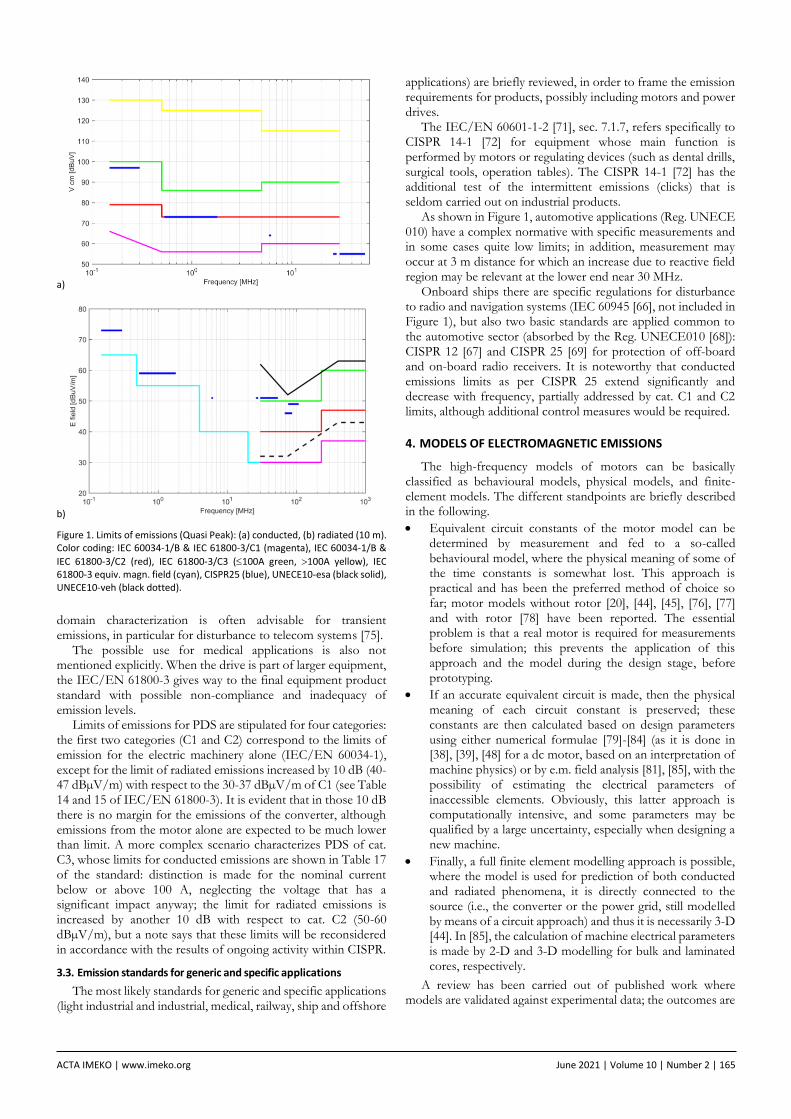
As shown in Figure 1, automotive applications (Reg. UNECE 010) have a complex normative with specific measurements and in some cases quite low limits; in addition, measurement may occur at 3 m distance for which an increase due to reactive field region may be relevant at the lower end near 30 MHz.
Onboard ships there are specific regulations for disturbance to radio and navigation systems (IEC 60945 [66], not included in Figure 1), but also two basic standards are applied common to the automotive sector (absorbed by the Reg. UNECE010 [68]): CISPR 12 [67] and CISPR 25 [69] for protection of off-board and on-board radio receivers. It is noteworthy that conducted emissions limits as per CISPR 25 extend significantly and decrease with frequency, partially addressed by cat. C1 and C2 limits, although additional control measures would be required.
4. MODELS OF ELECTROMAGNETIC EMISSIONS
The high-frequency models of motors can be basically classified as behavioural models, physical models, and finite-element models. The different standpoints are briefly described in the following.
• Equivalent circuit constants of the motor model can be determined by measurement and fed to a so-called behavioural model, where the physical meaning of some of the time constants is somewhat lost. This approach is practical and has been the preferred method of choice so far; motor models without rotor [20], [44], [45], [76], [77] and with rotor [78] have been reported. The essential problem is that a real motor is required for measurements before simulation; this prevents the application of this approach and the model during the design stage, before prototyping.
• If an accurate equivalent circuit is made, then the physical meaning of each circuit constant is preserved; these constants are then calculated based on design parameters using either numerical formulae [79]-[84] (as it is done in [38], [39], [48] for a dc motor, based on an interpretation of machine physics) or by e.m. field analysis [81], [85], with the possibility of estimating the electrical parameters of inaccessible elements. Obviously, this latter approach is computationally intensive, and some parameters may be qualified by a large uncertainty, especially when designing a new machine.
• Finally, a full finite element modelling approach is possible, where the model is used for prediction of both conducted and radiated phenomena, it is directly connected to the source (i.e., the converter or the power grid, still modelled by means of a circuit approach) and thus it is necessarily 3-D [44]. In [85], the calculation of machine electrical parameters is made by 2-D and 3-D modelling for bulk and laminated cores, respectively.
A review has been carried out of published work where models are validated against experimental data; the outcomes are
a)
b)
Figure 1. Limits of emissions (Quasi Peak): (a) conducted, (b) radiated (10 m). Color coding: IEC 60034-1/B & IEC 61800-3/C1 (magenta), IEC 60034-1/B &
IEC 61800-3/C2 (red), IEC 61800-3/C3 (100A green, 100A yellow), IEC 61800-3 equiv. magn. field (cyan), CISPR25 (blue), UNECE10-esa (black solid), UNECE10-veh (black dotted).

ACTA IMEKO | www.imeko.org June 2021 | Volume 10 | Number 2 | 166
discussed in the following focusing on the accuracy of the models, their reliability and simplicity of application.
For a 3 kW induction machine, in [45], the validation was extended beyond a simple geometry and preliminary results show an agreement within 10 dB. The model is simplified considering common-mode only, which is largely responsible for the largest emissions generated by these machines.
The equivalent circuit approach followed in [77] is approximately valid, in general, up to 10-15 MHz with respect to the measurement results, although the shown discrepancy is significant. One of the possible causes of discrepancy is the inaccuracy in the calculation of the inductance, which depends on the magnetic field analysis hypotheses taken into account.
The approach followed in [44], [76] is behavioural and the two proposed models are based on simplified equivalent circuits for all the drive elements, with parameters adjusted by fitting measurement results. The overall drive model is thus in agreement with measurements of conducted phenomena up to approximately 10-15 MHz. In [44], sample results of the 3-D modelling of a 3 kW motor are presented, but the validation of the approach (circuit simulation followed by 3-D model solved by Finite Integration Algorithm, similar to FDTD) was made only on a simple wire geometry and is thus not conclusive: the agreement is very good up to 90 MHz, except for a discrepancy of up to 10 dB between 35 and 50 MHz due to different heights of the radiating wire with respect to ground in measurement and simulations. In [76] a behavioural model is used to predict the conducted emissions of a motor drive system. The models of the four-wire shielded cable, the induction motor and the PWM voltage inverter (modelled as a common-mode source only) are used for the time-domain simulations of the adjustable speed drive. The comparison with measurement shows that conducted emissions can be predicted with acceptable accuracy up to 10 MHz; at higher frequency the discrepancy can be motivated by the noise introduced by the voltage probes and the oscilloscope characteristics.
A simple, but effective, formulation is proposed in [41], where common-mode currents are neglected in favour of differential-mode currents; the radiating properties of the machine are then modelled by equivalent loops under a far-field assumption, that holds for the higher portion of the frequency interval, approximately up to 50 MHz.
Analogously, for a DC motor, Benecke [38], [39], [48] presents an equivalent circuit approach, where the parameters are estimated by closed form expressions, that are made fitting measured impedances of some motor elements; the motor is subdivided into armature windings, commutator blades, brushes, other wiring and casing. The results are very encouraging with the terminal impedance fitting the radiated measurement results up to 1 GHz, with a negligible error almost everywhere on the frequency axis, except for an underestimated resonance peak at 600 MHz. The conducted emissions, on the contrary, match the experimental results only up to about 150 MHz, where the author says that supply line effects become predominant.
Finally, as regards the finite element modelling approach, finite element methods are based on standard e.m. codes, implementing for example Method of Moments, MoM (well suited for wire structures) and Finite Difference Time Domain, FDTD (particularly useful for the computation of switching transient effects) [86]. These models are normally fed by excitation currents that are in turn calculated by a full or equivalent circuit approach.
In conclusion, the determination of the e.m. emissions proceeds as follows:
• simulation of the circuit representation of the ensemble converter plus cable plus motor (the latter modelled as an equivalent circuit) and calculation of the excitation currents/voltages (the prediction of conducted voltages and currents may be very accurate as in [47]);
• application of the excitation signals to either an equivalent circuit [41] or finite element method model.
The limitations of this approach may be stated as:
• correct modelling of both common- and differential-mode circuits and estimation of the related sources and signals [42];
• adequate modelling of parasitic components and in particular turn-to-turn and turn-to-frame/core capacitance terms [87];
• correct application of the signals to the circuit elements and ports [45]; in particular, if a behavioural or equivalent circuit approach is chosen (also to match experimental observations and measurements at accessible terminals), common- and differential-mode signals need to be distinguished; depending on frequency and on the variability of the unknown and less controllable parameters, differential-to-common mode transformation may take place [45].
A simple worst-case model can be based on the assumption that the level of emissions is the maximum allowed by the limits of a given class or product, for emissions measured at the prescribed distance d*. The intensity of the e.m. field is then extrapolated to other distances d assuming a given dependency on distance. The presence of a near-field region around the machine and the reactive behaviour of the radiated emissions imply that the expected field intensity is much larger, no longer linear with distance (far field assumption): terms with the square and cubic power of distance should be considered as well. Machine feeding cables and their high-frequency currents can in fact be treated as Hertzian dipoles or as a chain of short dipoles, whose radiated field in the near-field region is composed of the electrostatic, induction and radiation field terms.
In Figure 2 the maximum allowed field intensity (emission limits at the standardized measurement distance) is extrapolated to shorter distances d characteristic of modern applications. The extrapolation is achieved with the following assumption: the radiating element is a small part of the overall power drive and
far-field formulas for dipole antennas are used (1/ = /(2 )), rather than those of large antennas. Extrapolation is carried out
including second-order terms (1/( d)2) and third-order terms
(1/( d)3); terms are rms composed assuming arbitrary time-phase relationship.
At distances of 1 m the extrapolated field intensity is significantly larger than the values obtained with a far-field assumption and at the limit of the separation of category of emissions (10 dB). A distance of 0.5 m is evidently a significant issue because all components in the most relevant frequency interval up to 100 MHz are well beyond control. It is underlined also that such components have lower wave impedance than in far field, and the effectiveness of conductive shields is reduced.

ACTA IMEKO | www.imeko.org June 2021 | Volume 10 | Number 2 | 167
5. EXPERIMENTAL CHARACTERIZATION OF E.M. EMISSIONS
There are several experimental results related to motor plus converter setups (such as for industrial or automotive ASD, where it is known that the converter is the major source of conducted and radiated emissions), but very few references report on the e.m. characteristics and contribution of the motor as a standalone item and/or the motor as a radiating source, converting conducted emissions.
The mechanism of emission for DC electric motors is related to the commutation at collector brushes and the arcing phenomena, while for AC motors it is due to the modulation of the machine magnetic field produced by the interaction of stator and rotor slots during rotation.
5.1. DC motor
The main source of e.m. emissions considered in literature is that of the commutation at motor brushes and arc ignition/extinction. Insights into the phenomenon of commutator sparking (flashovers) and arcing in electrical machines are given in [88], [89]. In [90] several methods are investigated and discussed to assess the quality of commutation in DC traction motors, such as motor current signature analysis, antenna pickup of sparking, photodiode measurement of sparking, acoustic analysis, and O3 and NOx detection. With these techniques poor commutation can be monitored, and actions can be taken to prevent sparking, which is associated to wide band e.m. emissions.
For example, motor current signature analysis requires the motor current to be analysed in the frequency domain at the bar-passing frequency, which is determined by multiplying the number of commutator bars by the speed of the motor. Two laboratory tests were carried out [90], the former on a 10 HP industrial motor, the latter on a standard 750 HP locomotive traction motor; both motors were in the steady state.
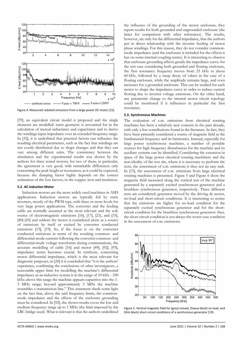
In [91], the analysis of the motor current takes advantage of wavelet analysis. Individual sparking events may be observed during the commutation even at low frequencies, making it possible to assess the quality of commutation even without expensive radiofrequency instrumentation. The radiation mechanism on the contrary is not directly from the electric arc itself, but from the motor windings, that are simulated with various circuit geometries, as described in detail in [18]. In Figure 3, the results of the calculated E-field emissions (under two different assumptions concerning the model of the arc, constant voltage and constant E-field) are shown and compared with measurement results [18]. By inspection of the two calculated curves shown in Figure 3, it is evident that the constant voltage assumption is reasonably valid and appropriate, as confirmed by the results of the measurement of the winding voltage and current during commutation. Suriano et al. [18] state that the emissions prediction by either constant-voltage or constant-electric field model of the commutation is inaccurate below 500 kHz. On the contrary, this limit was experimentally determined as the boundary between significant and negligible emissions from a large power DC motor [15], by comparing directly the measured emissions and background noise. The comparison is shown in Figure 4, where the difference is in excess of 20 dB below 500 kHz, and only of 10 dB up to 3.5 MHz (and then not appreciable).
The difference may be justified if the attenuation produced by motor enclosure and cable harness present in [15] is taken in account, whereas such provisions are not accounted for in [18]. Additionally, the motors considered in the two publications are of a different size. In general, motors with a larger rated power have additional shielding provided by the heavy enclosure, ventilation, etc. An accurate model of the winding impedance validated against experimental data is presented in [38], [39], [48] with remarkable accuracy up to 1 GHz for the terminal impedance and up to 150 MHz for the conducted emissions. In
a)
b)
Figure 2. Extrapolation of maximum emissions to (a) 1 m and (b) 0.5 m distance; IEC 61800-3 C1 (magenta), C2 (red), C3 (green); darker curves indicate inclusion of second order (thin) and third order (thick) terms.
Figure 3. Measured (grey curve) and calculated (hollow diamond, constant voltage arc assumption, and filled diamond, constant E-field arc assumption) DC motor emissions [18].
10 5
10 6
10 7
10 8
10 9 0
10
20
30
40
50
60
70
80
90
100
110
120
Frequency [Hz]
Ele
ctri
c F
ield
[dB
uV/m
]
ACTA IMEKO | www.imeko.org June 2021 | Volume 10 | Number 2 | 168
[39], an equivalent circuit model is proposed and the single elements are modelled: turns geometry is accounted for in the calculation of mutual inductance and capacitance and to derive the windings input impedance over an extended frequency range. In [32], it is underlined that practical factors can influence the resulting electrical parameters, such as the fact that windings are not evenly distributed due to shape changes and that they can vary among different units. The consistency between the simulation and the experimental results was shown by the authors for three tested motors; for two of them, in particular, the agreement is very good, with remarkable differences only concerning the peak height at resonances, as it could be expected, because the damping factor highly depends on the correct estimation of the loss factors, in the copper, iron and insulation.
5.2. AC Induction Motor
Induction motors are the most widely used machines in ASD applications. Induction motors are typically fed by static inverters, mostly of the PWM type, with three or more levels for very large power applications. The converter and the feeding cable are normally assumed as the most relevant and the sole source of electromagnetic emissions [16], [17], [21], and [33], [40]-[43] and seldom the motor is considered alone as a source of emissions by itself or excited by converter conducted emissions [15], [19]. So, if the focus is on the converter conducted emissions in terms of the resulting common- and differential-mode currents following the converter common- and differential-mode voltage waveforms during commutations, the accurate modelling of cable [16] and motor [49], [92], [93], impedance terms becomes crucial. In synthesis, concerning motor differential impedance, which is the most relevant for diagnostic purposes, in [20] it is concluded that “it is the authors’ experience, confirming the conclusions of other investigators, a reasonable upper limit for modelling the machine’s differential impedance as an inductive system is in the range of 10 kHz - 100 kHz; above this range the machine appears capacitive into the 1-3 MHz range; beyond approximately 3 MHz the machine resembles a transmission line.” This statement sheds some light on the fact that, above the said frequency limits, the common-mode impedance and the effects of the enclosure grounding must be considered. In [92], the shown results cover the low and medium frequency range up to 1 MHz (the limit imposed by the LRC bridge used). What is relevant is that the authors underlined
the influence of the grounding of the motor enclosure; they report results for both grounded and ungrounded enclosure (the latter for comparison with other references). The results, however, are only for the differential impedance, that the authors put in direct relationship with the inverter feeding of motor phase windings. For this reason, they do not consider common-mode impedance (and the enclosure is included for the effects it has on some internal coupling terms). It is interesting to observe that enclosure grounding affects greatly the impedance curve: for the test case considering both grounded and floating enclosure, the first resonance frequency moves from 25 kHz to about 60 kHz, followed by a steep decay of values in the case of a floating enclosure, while the amplitude remains large, and even increases for a grounded enclosure. This can be studied for each motor to shape the impedance curve in order to reduce current flowing due to inverter voltage emissions. On the other hand, any parametric change to the internal motor circuit topology could be monitored if it influences in particular the first resonance.
5.3. Synchronous Machines
The evaluation of e.m. emissions from electrical rotating machines has been a relatively new concern in the past decade, with only a few contributions found in the literature. In fact, they have been primarily considered a source of magnetic field at the fundamental frequency and its harmonics. Instead, especially for large power synchronous machines, a number of possible sources for high frequency disturbances for the machine and its auxiliary systems can be identified. Considering the extension in space of the large power electrical rotating machinery and the non-ideality of the test site, where it is necessary to perform the tests, the assessment of e.m. emissions is thus not an easy task. In [15], the assessment of e.m. emissions from large electrical rotating machines is presented. Figure 5 and Figure 6 show the magnetic field measured along the vertical axis of the machine generated by a separately excited synchronous generator and a brushless synchronous generator, respectively. Three different tests are considered: generator moved by the driving dc motor, no-load and short-circuit conditions. It is interesting to notice that the emissions are higher for no-load condition for the separately excited synchronous generator and for the short-circuit condition for the brushless synchronous generator: thus, the short-circuit condition is not always the worst-case condition in the assessment of e.m. emissions.
Figure 4. Measured radiated emissions from a large power DC motor [15].
Figure 5. Vertical magnetic field for (grey) moved, (heavy black) no-load, and (thin black) short-circuit conditions of a synchronous generator [19].

ACTA IMEKO | www.imeko.org June 2021 | Volume 10 | Number 2 | 169
In [19], the metrological characteristics are pointed out, that describe the quality and reliability of experiments. In particular, the quality of measurements is evaluated in terms of repeatability (computed as the standard deviation of repeated measurements) and reproducibility (computed as difference of average recordings for different generators of the same type), shown in Figure 7 (a) and (b), respectively.
6. UNCERTAINTY AND SYSTEMATIC ERRORS
Any statement of compliance to limits and assessment of a quantity brings along the concept of uncertainty. In the present case the measurement of conducted and radiated emissions is disciplined by the set of CISPR 16 standards, and in particular CISPR 16-4-1. However, the focus of CISPR standards is on EMC measurements carried out on equipment of small-medium dimensions that for radiated emissions fit one of the advised facilities, namely open area test site (OATS), semi-anechoic chamber (SAC), fully anechoic chamber (FAC), TEM and GTEM cells. In addition, the standards do not account for ancillary equipment with a potentially significant emission contribution (such as lubricating and cooling system, auxiliary converters and machinery to drive or load the machine under test). These factors were extensively discussed in [19], addressing the problem by means of experimental results and analysing repeatability and Type A uncertainty.
Smaller equipment (that may be a motor or a complete drive) can fit standardized test facilities and may be tested more easily with a better documented uncertainty. However, one more factor comes into play: the purpose of EMC standards is to test the equipment with the minimum ancillary equipment for operation in an environment and with a test setup that maximize reproducibility. More and more often modern motors and drives are used embedded in OEM (Other Equipment Manufacturer) products and in compact applications featuring high power density, such as automotive (and in particular electric vehicles), avionics, medical and laboratory (in particular next to sensors and diagnostic instruments) or within electrical appliances (such as ventilation and conditioning, for which in [56] we see exemplification of typical issues of compliance).
With a parallel to other systems featuring large apparatus, relevant factors with impact on uncertainty and reproducibility are: i) emissions from a long cable line connected to the motor
or generator, that can be borrowed from the scenario of the catenary feeding line in electrified railways [94]; ii) moving source in case of vehicles and electrified transports, as well as moving industrial apparatus (e.g. for positioning or tooling); iii) variability of operating conditions for large machines that cannot be bench tested under satisfactory conditions.
The electromagnetic environment is quite different from a nearly open area in far-field conditions and no scattering and reflections. In addition, the distance at which possible victims are located is very short, implying that the electromagnetic field components are in the reactive region up to quite a high frequency. The compactness of the setup that reproduces the final application impacts directly on the suitable antennas to adopt that are different from those considered by CISPR and generally accepted for standardized tests: antennas of very small dimensions have a low sensitivity for which the background noise is very close not to say above the limits without using pre-amplification. Second, the reactive behaviour of the measured emissions, with a dependency of the square to cubic power of distance, increases the uncertainty due to errors of positioning and measurement of distance, and influences also the expected level of emissions onto nearby victims in the final installation.
Figure 6. Vertical magnetic field for (grey) moved, (heavy black) no-load, and (thin black) short-circuit conditions of a brushless synchronous generator [15].
Figure 7. (a) Repeatability as standard deviation and (b) reproducibility as difference of averages for the magnetic field components of two identical synchronous generators [19].

ACTA IMEKO | www.imeko.org June 2021 | Volume 10 | Number 2 | 170
Among the environmental conditions of the installation temperature and vibration are particularly important for their influence on emissions, taking into account the widespread use of motors and power drives in automotive, avionic, naval and offshore applications, all characterized by a wide range of the two environmental parameters. Environmental factors represent to some extent a source of systematic error, as for the offset with respect to those applied during EMC tests for certification. The variability around the typical operating points is an additional source of uncertainty.
In [95] the influence of vibration on conducted emissions of a DC motor was measured and compared against the limits of conducted emissions for Class 1 of CISPR 25: besides a violation of limits by about 10 dB caused by commutation arcing in normal conditions, the tests carried out when vibration is applied (simulating a realistic condition of use) show an increase of conducted emissions by about another 5 dB on average.
7. CONCLUSIONS
This work has discussed the problem of electromagnetic compliance of electric machinery and power drives, by introducing and reviewing the normative references for electromagnetic emissions, the available modelling approaches and their accuracy, and the measurement methods including the influence of setup and environment, besides the different behaviour of various type of machines.
For normative limits Section 2 has distinguished standards for generic and specific applications, addressing the problem of applying the standards and limits for the final application. Focus is equally divided between conducted and radiated emissions, although the latter is more extensively covered both for a lack of direct connection to the public distribution network and for a particular interest for diagnostic purposes.
Various modelling approaches have been reviewed in Section 3, as a replacement of measurements discussed in Section 4 and as a means of prediction of emissions of the machine or power drive installed and operating in its final application. Models in general require some tuning and supplemental information for parameters and input quantities, achievable only by means of measurements, that seem thus an irreplaceable element. Selected models are reported as having good accuracy, in particular up to some tens of MHz, able to cover the largest emissions also of power drives, that as a rule of thumb have an interval of emissions about one/two orders of magnitude more extended than electrical machines alone.
Available references for measurements were also discussed both for the main features of electromagnetic emissions of different type of machines, and for the metrological performance of systematic errors, repeatability and uncertainty.
REFERENCES
[1] Directive 2014/30/EU of the European Parliament and of the Council of 26 February 2014 on the harmonisation of the laws of the Member States relating to electromagnetic compatibility. Online [Accessed 20 June 2021] http://data.europa.eu/eli/dir/2014/30/oj
[2] IEC 60034-1, Rotating electrical machines — Part 1: Rating and performance, International Electrotechnical Commission: Geneva, Switzerland, 2004.
[3] IEC 60034-1, Rotating electrical machines — Part 1: Rating and performance, International Electrotechnical Commission: Geneva, Switzerland, 2010.
[4] IEC 60034-1, Rotating electrical machines — Part 1: Rating and performance, International Electrotechnical Commission:
Geneva, Switzerland, 2017. [5] IEC 61800-1, Adjustable speed electrical power drive systems -
Part 1: General requirements - Rating specifications for low voltage adjustable speed DC power drive systems, International Electrotechnical Commission: Geneva, Switzerland, 2021.
[6] IEC 61800-2, Adjustable speed electrical power drive systems - Part 2: General requirements - Rating specifications for low voltage adjustable speed a.c. power drive systems, International Electrotechnical Commission: Geneva, Switzerland, 2015.
[7] IEC 61800-3, Adjustable speed electrical power drive systems - Part 3: EMC requirements and specific test methods, International Electrotechnical Commission: Geneva, Switzerland, 2017.
[8] IEC 61800-3, Adjustable speed electrical power drive systems - Part 3: EMC requirements and specific test methods, International Electrotechnical Commission: Geneva, Switzerland, 2004 + Amd1:2011
[9] IEC 61000-6-1, Electromagnetic compatibility (EMC) - Part 6-1: Generic standards - Immunity for residential, commercial and light-industrial environments, International Electrotechnical Commission: Geneva, Switzerland, 2016.
[10] IEC 61000-6-2, Electromagnetic compatibility (EMC) - Part 6-2: Generic standards - Immunity for industrial environments, 2016.
[11] IEC 61000-6-3, Electromagnetic compatibility (EMC) - Part 6-3: Generic standards - Emission standard for residential, commercial and light-industrial environments, International Electrotechnical Commission: Geneva, Switzerland, 2020.
[12] IEC 61000-6-4, Electromagnetic compatibility (EMC) - Part 6-4: Generic standards - Emission standard for industrial environments, International Electrotechnical Commission: Geneva, Switzerland, 2018.
[13] IEEE Std. 1566, Standard for Performance of Adjustable Speed AC Drives Rated 375 kW and Larger, IEEE, Piscataway, NJ, USA, 2015.
[14] A. Mariscotti, Measurement Procedures and Uncertainty Evaluation for Electromagnetic Radiated Emissions from Large Power Electrical Machinery, IEEE Trans. Instr. Meas. 56 (2007), pp. 2452-2463. DOI: 10.1109/TIM.2007.908351
[15] P. Ferrari, A. Mariscotti, A. Motta, P. Pozzobon, Electromagnetic Emissions from Electrical Rotating Machinery, IEEE Trans. Energy Conv., 16 (1) (2001), pp. 68-73. DOI: 10.1109/60.911406
[16] S. A. Pignari, A. Orlandi, Long cable effects on conducted emissions levels, IEEE Trans. Electrom. Compat., 45 (1) (2003), pp.43-54. DOI: 10.1109/TEMC.2002.808023
[17] U. Reggiani, A, Massarini, L. Sandrolini, M. Ciccotti, X. Liu, D. W. P. Thomas, C. Christopoulos, Experimental verification of predicted electromagnetic fields radiated by straight interconnect cables carrying high-frequency currents, Proc. IEEE Power Tech Conf., Bologna, 23-26 June 2003, 5 pp. DOI: 10.1109/PTC.2003.1304166
[18] C. R. Suriano, J. R. Suriano, G. Thiele, T. W. Holmes, Prediction of Radiated Emissions from DC Motors, Proc. IEEE Int. Symp. on EMC, Colorado, USA, 24-28 August 1998, pp. 790-795 vol.2. DOI: 10.1109/ISEMC.1998.750300
[19] A. Mariscotti, Assessment of Electromagnetic Emissions from Synchronous Generators and its Metrological Characterization, IEEE Trans. Instrum. Meas. 59 (2) (2010), pp.450-457. DOI: 10.1109/TIM.2009.2024696
[20] G. L. Skibinski, R. J. Kerkman, D. Schlegel, EMI emissions of modern PWM AC drives, IEEE Ind. Appl. Magazine 5(6) 1999, pp. 47-81. DOI: 10.1109/2943.798337
[21] M. Wisniewski, R. Kubichek, J. Pierre, EMI emissions up to 1 GHz from adjustable speed drives, Proc. of 27th Annual Conf. of the IEEE Ind. Electr. Society, IECON, Dever, CO, US, 29 November – 2 December, 2001, pp. 113-118 vol.1. DOI: 10.1109/IECON.2001.976464
[22] E. T. Arntzen, R. F. Kubichek, J. W. Pierre, S. Ula, Initial findings in electromagnetic emissions above 30 MHz from power inverters and variable speed motor controllers, Proc. IEEE Int. Symp. on EMC, 18-22 August 1997, Austin, TX, USA, pp. 106-108. DOI: 10.1109/ISEMC.1997.667550

ACTA IMEKO | www.imeko.org June 2021 | Volume 10 | Number 2 | 171
[23] S. Ogasawara, H. Ayano, H. Akagi, Measurement and reduction of EMI radiated by a PWM inverter-fed AC motor drive system, IEEE Trans. Ind. Appl. 33 (4) (1997), pp. 1019-1026. DOI: 10.1109/28.605744
[24] A. Dolente, U. Reggiani, L. Sandrolini, Comparison of radiated emissions from different heatsink configurations, Proc. of IEEE 6th Int. Symp. on Electrom. Compat. and Electrom. Ecology, St. Petersburg, Russia, 21-24 June 2005, pp. 49-53. DOI: 10.1109/EMCECO.2005.1513059
[25] I. Montanari, EMI measurements for aging control and fault diagnosis in active devices, Proc. of IEEE 6th Int. Symp. on Electromagnetic Compatibility and Electromagnetic Ecology, St. Petersburg, Russia, 21-24 June 2005, pp. 183-186. DOI: 10.1109/EMCECO.2005.1513096
[26] Y. Kazakov, N. Morozov, E. Shumilov, Analysis of the electromagnetic radiation distribution of frequency-controlled electric machines in order to diagnose their performance, Proc. of Int. Conf. on Electrotechn, Complexes and Systems (ICOECS), Ufa, Russia, 27 October 2020, pp. 1-4. DOI: 10.1109/ICOECS50468.2020.9278477
[27] A. Mariscotti, A. Ogunsola, L. Sandrolini, Survey of models and reference data for prediction of e.m. field emissions from electrical machinery Proc. of the IEEE Symp. on Diagn. for Elec. Machines, Pow. Electron. & Drives, Bologna, Italy, 5-8 September 2011, pp. 350-355. DOI: 10.1109/DEMPED.2011.6063647
[28] D. Burow, J. K. Nelson, S. Salon, J. Stein, High Frequency Synchronous Generator Model for Electromagnetic Signature Analysis, Proc. of the 20th Intern. Conf. on Electr. Mach., Marseille, France, 2-5 September 2012, pp. 1712-1716. DOI: 10.1109/ICELMach.2012.6350111
[29] D. Burow, J. K. Nelson, S. Salon, J. Stein, High Frequency Synchronous Generator Modeling and Testing for Electromagnetic Signature Analysis, Proc. of the Intern. Conf. Electr. Mach., Berlin, Germany, 2-5 September 2014, pp. 1894-1900. DOI: 10.1109/ICELMACH.2014.6960442
[30] C. R. Suriano, J. R. Suriano, G. Thiele, T. W. Holmes, Prediction of Radiated Emissions from DC Motors, Proc. of IEEE EMC Intern. Symp. Electrom. Comp., Denver, USA, 24-28 August 1998, pp. 790-795 vol.2 . DOI: 10.1109/ISEMC.1998.750300
[31] J. Suriano, C. M. Ong, Modeling of Electromechanical and Electromagnetic Disturbances in DC Motors, Proc. of the Nat. Symp. Electrom. Comp., Denver, USA, 23-25 May 1989, pp. 258-262. DOI: 10.1109/NSEMC.1989.37190
[32] F. Pavlovcic, Commutator Motors as EMI Sources, Proc. of the Intern. Symp. on Pow. Electron., Electr. Drives, Autom. and Motion, Pisa, Italy, 14-16 June 2010, pp. 1789-1793. DOI: 10.1109/SPEEDAM.2010.5545039
[33] G. Antonini, S. Cristina, A. Orlandi, A Prediction Model for Electromagnetic Interferences Radiated by an Industrial Power Drive System, IEEE Trans. Ind. App. 35 (1999), pp.870-876. DOI: 10.1109/28.777196
[34] D. L. Sanders, J. P. Muccioli, A. A. Anthony, D. S. Walz, D. Montone, Using Image Planes on DC Motors to Filter High Frequency Noise, Proc. of the IEEE Intern. Symp. Electrom. Comp., Silicon Valley, CA, USA, 9-13 August 2004, pp. 621-625 vol.2. DOI: 10.1109/ISEMC.2004.1349870
[35] H. Miloudi, A. Bendaoud, M. Miloudi, S. Dickmann, S. Schenke, Common Mode and Differential Mode Characteristics of AC Motor for EMC Analysis, Proc. of the Intern. Symp. Electrom. Comp. - EMC EUROPE, Sept. 5-9, 2016, Wroclaw, Poland. DOI: 10.1109/EMCEurope.2016.7739260
[36] Z. Duan, X. Wen, A new analytical conducted EMI prediction method for SiC motor drive systems, eTransportation, 3 (2020), pp.1-11. DOI: 10.1016/j.etran.2020.100047
[37] P.L. Alger, The induction machine, Gordon & Breach, 1965. [38] J. Benecke, S. Dickman, Analytical HF Model for Multipole DC
Motors, Proc. of 18th Int. Zurich Symp. on EMC, Munich, Germany, Sept. 24-28, 2007, 201-204.
DOI: 10.1109/EMCZUR.2007.4388230 [39] J. Benecke, S. Dickman, Analytical HF Model of a Low Voltage
DC Motor Armature Including Parasitic Properties, Proc. IEEE Int. Symp. on EMC, Hawaii, USA, July 9-13, 2007. DOI: 10.1109/ISEMC.2007.250
[40] G. L. Giuliattini Burbui, U. Reggiani, L. Sandrolini, Prediction of low-frequency electromagnetic interferences from SMPS, 2006 IEEE International Symp. on Electromagnetic Compatibility EMC 2006, Portland, USA, Aug. 14-18, 2006, pp. 472-477. DOI: 10.1109/ISEMC.2006.1706350
[41] F. Della Torre, A. P. Morando, Study on far-field radiation from three-phase induction machines, IEEE Trans. Electromagn. Compat. 51(4) (2009), pp. 928-936. DOI: 10.1109/TEMC.2009.2027814
[42] G. Grandi, D. Casadei, U. Reggiani, Analysis of common mode and differential mode HF current components in PWM inverter fed ac motors, Proc. IEEE 19th Annual Power Electronics Specialist Conf., Fukuoka, Japan, 1998, 1146-1151. DOI: 10.1109/PESC.1998.703149
[43] G. Grandi, D. Casadei, U. Reggiani, Common- and differential- mode HF current components in AC motors supplied by voltage source inverters, IEEE Trans. on Power Electronics, 19 (1), 2004, 16-24. DOI: 10.1109/TPEL.2003.820564
[44] F. Costa, E. Laboure, V. Lavabre, M. Patra, L. Paletta, Validation of Numerical Calculations of the conducted and radiated Emissions: Application to a variable Speed Drive, Proc. of IEEE 31st Annual Power Electronics Specialist Conf., Ireland, 2000. DOI: 10.1109/PESC.2000.879939
[45] F. Costa, C. Vollaire, R. Meuret, Modeling of Conducted Common Mode Perturbations in Variable-Speed Drive Systems, IEEE Trans. Electrom. Compat. 47 (4) (2005), pp. 1012-1021. DOI: 10.1109/TEMC.2005.857365
[46] J. Penman, H. G. Sedding, B. A. Lloyd, W. T. Fink, Detection and location of interturn short circuits in the stator windings of operating motors, IEEE Trans. En. Conv. 9 (4) (1994), pp. 652-658. DOI: 10.1109/60.368345
[47] J. E. Makaran, J. LoVetri, BLDC motor and drive conducted RFI simulation for automotive applications, IEEE Trans. Electrom. Comp. 45 (2) (2003), pp. 316-329. DOI: 10.1109/TEMC.2003.811304
[48] J. Benecke, Impedance and Emission Optimization of Low Voltage DC Motors for EMC Compliance, IEEE Trans. on Industrial Electronics, 58 (9), 2011, 3383-3389. DOI: 10.1109/TIE.2010.2084978
[49] J. Luszcz, K. Iwan, Conducted EMI propagation in Inverter-fed AC motor, Magazine of Electrical Power Quality and Utilization, 2 (1), 2006, 47-51.
[50] CISPR 11, Industrial, scientific and medical equipment – Radio-frequency disturbance characteristics – Limits and methods of measurement, 2015.
[51] J. Geng, R. Jin, Y. Fan, B. Liu, J. Li, Y. Cheng, Z. Wang, The study on electromagnetic compatibility of DC electric motor in HAPS, Aerospace Sci. and Techn., 9 (2005), pp.617-625. DOI: 10.1016/j.ast.2005.01.004
[52] I. M. Ahmad, A. Eroglu, C. Pomalaza-Raez, M. Li, Simulation and Modeling Technique for EMI measurement of the ECM motors in HVAC Systems, Proc. of the IEEE 7th Ann. Ubiq. Comp., Electron. & Mob. Comm. Conf. (UEMCON), Oct. 20-22, 2016, New Yor, USA. DOI: 10.1109/UEMCON.2016.7777877
[53] M. I. Buzdugan, H. Balan, Electromagnetic compatibility issues of brushless speed drives, Intern. Univ. Pow. Eng. Conf. (UPEC), Sept. 6-9, 2016, Coimbra, Portugal. DOI: 10.1109/UPEC.2016.8114064
[54] I. Oganezova, R. Kado, B. Khvitia, A. Gheonjian, R. Jobava, Simulation of Conductive and Radiated Emissions from a Wiper Motor According to CISPR 25 Standard, IEEE Intern. Symp. Electrom. Comp., Aug. 16-22, 2015, Dresden, Germany. DOI: 10.1109/ISEMC.2015.7256296
[55] J. E. Makaran, J. LoVetri, Prediction of Conducted RFI Emissions in BLDC Motors for Automotive Applications, IEEE Intern. Symp. Electrom. Comp., Aug. 13-17, 2001, Montreal, Canada.

ACTA IMEKO | www.imeko.org June 2021 | Volume 10 | Number 2 | 172
[56] I. T. Arntzen, R.F. Kubichek, J. W. Pierre, S. Ula, Initial Findings in Electromagnetic Emissions above 30 MHz from Power Inverters and Variable Speed Motor Controllers, IEEE Intern. Symp. Electrom. Comp., Aug. 18-22, 1997, Austin, Texas, USA. DOI: 10.1109/ISEMC.1997.667550
[57] A. A. Adam, K. Gulez, S. Koroglu, Stray magnetic field distributed around a PMSM, Turk J Elec. Eng. & Comp. Sci., vol.19, 2011, pp.119-131. DOI: 10.3906/elk-1003-404
[58] O. Hasnaoui, Electromagnetic Interferences and Common Mode Voltage Generated by Variable Speed AC Motors, Intern. Conf. Electr. Sci. and Techn. in Maghreb, Nov. 3-6, 2014, Tunis, Tunisia. DOI: 10.1109/CISTEM.2014.7076990
[59] J. Lee, K. Jung, S. Park, Simulation of Radiated Emissions from a Low Voltage BLDC Motor, Intern. Symp. on Antennas and Propagation (ISAP), Oct. 23-26, 2018, Busan, South Korea.
[60] M. Ma, Z. Xu, W. Tao, X. Zhang, Z. Ji, H. Li, Environmental Leakage Magnetic Field Analysis of High-powered PM Linear Motor with Inverted U Structure, 22nd Intern. Conf. Electr. Mach. and Sys., Aug. 11-14, 2019, Harbin, China. DOI: 10.1109/ICEMS.2019.8921821
[61] J. Guo, C. Wang, Y. Ding, L. Jiang, Y. Lv, Suppression of electromagnetic radiation emission from electric vehicles: an engineering practical approach, EMC Sapporo & APEMC, June 3-7, 2019, pp.476-479. DOI: 10.23919/EMCTokyo.2019.8893721
[62] J. Guo, Y. Zhang, G. Zhang, X. Zhang, G. Jiang, Analysis on an Electromagnetic Compatibility Engineering Trouble Shooting Case of Electric Vehicle, EMC Sapporo & APEMC, June 3-7, 2019, pp.464-467. DOI: 10.23919/EMCTokyo.2019.8893937
[63] R. Armstrong, L. Dawson, A. J. Rowell, C. A. Marshman, A. R. Ruddle, The Effect of Fully Electric Vehicles on the Low Frequency Electromagnetic Environment, IEEE Intern. Symp. Electrom. Comp., Dresden, Germany, 16-22 August 2005, pp. 662-667. DOI: 10.1109/ISEMC.2015.7256242
[64] L. Zhai, L. Lin, C. Song, X. Zhang, Mitigation Conducted-EMI Emission Strategy Based on Distributed Parameters of Power Inverter System in Electric Vehicle, IEEE 2nd Ann. South. Pow. Electron. Conf. (SPEC), Auckland, New Zealand, 5-8 December 2016, pp. 1-4. DOI: 10.1109/SPEC.2016.7846104
[65] IEC 60533, Electrical and electronic installations in ships – Electromagnetic compatibility (EMC) – Ships with a metallic hull, 2015, Geneva, Switzerland.
[66] IEC 60945, Maritime navigation and radiocommunication equipment and systems – General requirements – Methods of testing and required test results, 2002, Geneva, Switzerland.
[67] CISPR 12, Vehicles, boats and internal combustion engines – Radio disturbance characteristics – Limits and methods of measurement for the protection of off-board receivers, 2009.
[68] Reg. UNECE 10, Uniform provisions concerning the approval of vehicles with regard to electromagnetic compatibility, Rev. 5, 2014.
[69] CISPR 25, Vehicles, boats and internal combustion engines – Radio disturbance characteristics – Limits and methods of measurement for the protection of on-board receivers, 2008.
[70] CISPR 36, Electric and hybrid road vehicles – Radio disturbance characteristics – Limits and methods of measurement for the protection of off-board receivers below 30 MHz, 2016 (draft CISPR/D/429/CD)
[71] IEC 60601-1-2, Medical electrical equipment Part 1-2: General requirements for basic safety and essential performance – Collateral Standard: Electromagnetic disturbances – Requirements and tests, 2014+amd1:2020, Geneva, Switzerland.
[72] CISPR 14-1, Electromagnetic compatibility – Requirements for household appliances, electric tools and similar apparatus – Part 1: Emission, 2020.
[73] J. G. Fetter, D. G. Benditt, M. S. Stanton, Electromagnetic Interference from Welding and Motors on Implantable Cardioverter-Defibrillators as Tested in the Electrically Hostile Work Site, J. Amer. Coll. Cardiol., vol.28, August 1996, pp.423-427.
DOI: 10.1016/0735-1097(96)00147-7 [74] A. Mariscotti, Normative Framework for the Assessment of the
Radiated Electromagnetic Emissions from Traction Power Supply and Rolling Stock, IEEE Veh. Pow. and Prop. Conf., Hanoi, Vietnam, 14-17 October 2019, pp. 1-7. DOI: 10.1109/VPPC46532.2019.8952487
[75] A. Mariscotti, A. Marrese, N. Pasquino, Time and frequency characterization of radiated disturbance in telecommunication bands due to pantograph arcing, Measurement, vol.46, 2013, pp. 4342-4352. DOI: 10.1016/j.measurement.2013.04.054
[76] M. Moreau, N. Idir, Ph. Le Moigne, J.J. Franchaud, Utilization of a Behavioural Model of Motor Drive Systems to Predict the Conducted Emissions, Proc. 39th IEEE Power Electronics Specialist Conf., Rhodes, Greece, 15-19 June 2008, pp. 4387-4391. DOI: 10.1109/PESC.2008.4592652
[77] K. Maki, H. Funato, L. Shao, Motor modeling for EMC simulation by 3-D electromagnetic field Analysis, Proc. IEEE Int. Electric Machines and Drives Conf., 3-6 May 2009, pp.103-108. DOI: 10.1109/IEMDC.2009.5075190
[78] R. Naik, T. A. Nondahl, M. J. Melfi, R. Schiferl, J. S. Wang, Circuit model for shaft voltage prediction in induction motors fed by PWM based AC drives, IEEE Trans. on Industry Applications, 39 (5), 2003, pp.1294-1299. DOI: 10.1109/TIA.2003.816504
[79] A. Muetze, A. Binder, Calculation of motor capacitances for prediction of the voltage across the bearings in machines of Inverter-based drive systems, IEEE Trans. on Industry Applications, 43 (3), 2007, pp.665-672. DOI: 10.1109/TIA.2007.895734
[80] B. Mirafzal, G. L. Skibinski, R. M. Tallam, D. W. Schlegel, R. A. Lukaszewski, Universal induction motor model with low-to-high frequency-response characteristics, IEEE Trans. on Industry Applications, 43 (5), 2007, pp.1233-1246. DOI: 10.1109/TIA.2007.904401
[81] O. A. Mohammed, S. Ganu, N. Abed, S. Liu, Z. Liu, High frequency PM synchronous motor model determined by FE analysis, IEEE Trans. on Magnetics, 42 (4), 2006, pp.1291-1294. DOI: 10.1109/TMAG.2006.872412
[82] C. Chen, X. Xu, Modeling the conducted EMI emission of an electric vehicle (EV) traction drive, Proc. IEEE Int. Symp. on Electromagnetic Compatibility, Aug. 24-28, 1998, Denver, CO, USA, vol. 2, pp.796–801. DOI: 10.1109/ISEMC.1998.750301
[83] C. Chen, Characterizing the generation & coupling mechanisms of electromagnetic interference noise from an electric vehicle traction drive up to microwave frequencies, Proc. 15th Annual IEEE Applied Power Electronics Conf. and Exposition New Orleans, LA, USA, 6-10 February 2000, vol. 2, pp.1170–1176. DOI: 10.1109/APEC.2000.822835
[84] L. Arnedo, K. Venkatesan, High Frequency Modeling of Induction Motor Drives for EMI and Overvoltage Mitigation Studies, Proc. IEEE Int. Conf. on Electric Machines and Drives Madison, WI, USA, 1-4 June 2003, vol. 1, pp.468–474. DOI: 10.1109/IEMDC.2003.1211305
[85] V. Venegas, J. L. Guardado, E. Melgoza, M. Hernandez, A finite element approach for the calculation of electrical machine parameters at high frequencies, Proc. IEEE PES General Meeting Tampa, FL, USA, 24-28 June 2007, pp. 1-5. DOI: 10.1109/PES.2007.386274
[86] G. Ala, M. C. Di Piazza, G. Tine, F. Viola, G. Vitale, Numerical Simulation of Radiated EMI in 42 V Electrical Automotive Architectures, IEEE Trans. Magn. 42 (4) (2006), pp. 879-882. DOI: 10.1109/TMAG.2006.871440
[87] F. Perisse, P. Werinsky, D. Roger, High frequency behaviour of AC machine: application to turn insulation aging diagnostic, Proc. IEEE Int. Symp. on Electrical Insulation, Toronto, Canada, 11-14 June 2006, 555-559. DOI: 10.1109/ELINSL.2006.1665379
[88] K. Padmanabhan, A. Srinivisan, Some important aspects in the phenomenon of commutator sparking, IEEE Trans. on Power Apparatus and Systems, 84 (1965), pp.396-404. DOI: 10.1109/TPAS.1965.4766211
[89] M. J. B.Turner, B. R. G. Swinnerton, Sparking and arcing in

ACTA IMEKO | www.imeko.org June 2021 | Volume 10 | Number 2 | 173
electrical machines, Proceedings IEE, 113 (8) (1966), pp.1376-1386. DOI: 10.1049/piee.1966.0235
[90] M. P. Treanor, G.B Kliman, Incipient Fault Detection in Locomotive DC Traction Motors, Proc. of 49th Meeting of the Society for Machinery Failure Prevention Technology, Virginia Beach, USA, 1995, 221-230.
[91] G. B. Kliman, D. Song, R. A. Koegl, Remote monitoring of DC motor sparking by wavelet analysis of the current, Proc. 4th IEEE Int. Symp. on Diagnostics for Electric Machines, Power Electronics and Drives, SDEMPED Atlanta, GA, USA, 24-26 August 2003. DOI: 10.1109/DEMPED.2003.1234542
[92] B. A. Potter, S. A. Shirsavar, M. D. McCulloch, Study of the variation of the input impedance of induction machines with frequency, IET Electrical Power Applications, 1 (1) (2007), pp. 36-
42. DOI: 10.1049/iet-epa:20050524
[93] A. Boglietti, A. Cavagnino, M. Lazzari, Experimental High-Frequency Parameter Identification of AC Electrical Motors, IEEE Trans. Ind. App. 43 (2007), pp.23-29. DOI: 10.1109/TIA.2006.887313
[94] A. Mariscotti, Critical Review of EMC Standards for the Measurement of Radiated Electromagnetic Emissions from Transit Line and Rolling Stock, Energies, 14 (2020) 759, pp. 1-26. DOI: 10.3390/en14030759
[95] S. M. Prusu, C. Munteanu, A. Răcăşan, F.-I. Pop, R.-M. Gliga, The Influence of Vibrations on Conducted Emissions, 7th Intern. Conf. Modern Pow. Sys. (MPS), Cluj-Napoca, Romania, 6-9 June 2017, pp. 1-5. DOI: 10.1109/MPS.2017.7974460