review of quad-axle groups discussion paper - ntce72697e1-59b... · title review of quad-axle...
TRANSCRIPT

Review of quad-axle groups
Discussion paper
March 2016

Report outline
Title Review of quad-axle groups
Type of report Discussion paper
Purpose Public consultation
Abstract This project assesses the feasibility of revising mass limits for quad-
axle groups, without requiring performance-based standards
approval. It involves an engineering analysis of the current and
proposed quad-axle mass limits and recommends revised mass
limits.
Submission
details
Submissions will be accepted until 26 April 2016 online at
www.ntc.gov.au or by mail to:
Attn: Review of quad-axle groups
National Transport Commission
Level 15/628 Bourke Street
Melbourne VIC 3000
Key words Quad axles, PBS, mass limits, GML, HML, bridge, assessment,
heavy vehicles, high productivity vehicles
Contact National Transport Commission
Level 15/628 Bourke Street
Melbourne VIC 3000
Ph: (03) 9236 5000
Email: [email protected]
www.ntc.gov.au
ISBN 978-1-921604-89-8

1
Contents
Executive summary 3
1 Context 6
1.1 Objectives 6
1.2 Quad-axle definition 6
1.3 The problem 7
1.4 Project scope 7
2 Consultation 9
2.1 Questions to consider 9
2.2 How to submit 9
3 Current quad-axle policy 11
3.1 Current usage of quad-axle groups 11
4 Barriers to increasing mass limits for quad-axle groups 12
4.1 Safety of short-span bridges 12
4.2 Vehicle geometry 13
4.3 Performance assurance of PBS approval 14
4.4 Consequential impacts of changes to quad-axle group mass limits 14
5 Engineering analysis: key findings 15
5.1 Key findings from the engineering analysis 16
5.2 Conclusions from the engineering analysis 19
6 Options 21
6.1 Option 1: Retain existing arrangements 21
6.2 Option 2: Allow access at 24 tonnes GML and 27 tonnes HML 21
6.3 Option 3: Allow restricted access at 24 tonnes GML and 27 tonnes HML 22
6.4 Option 4: Allow restricted access at 24 tonnes GML and 27 tonnes HML and
review load factor 23
6.5 Preferred option 23
7 Implementation 25
8 Next steps 27
9 References and further reading 28
10 Appendix A: Glossary 29
11 Appendix B: Acronyms 30
12 Appendix C: Critical linkages 31
13 Appendix D: Engineering analysis 1

2
List of tables
Table 1. Mass load limits 7
Table 2. Quad-axle group mass limits for semi-trailers and B-doubles 8
Table 3. Quad-axles under PBS 11
Table 4. Total quad-axles vehicles 11
Table 5. Vehicles tested in the engineering analysis 15
Table 6. Quad-axle group engineering assessment results 20
Table 7. Comparison between vehicles fitted with tri-axle and quad-axle groups 22
Table 8. Project schedule 27
List of figures
Figure 1. Quad-axle semitrailer combination 6
Figure 2. PBS swept path analysis 16
Figure 3. Measuring clear spacing between axle groups 18
Figure 4. Continuous span bridge 18
Figure 5. T44 results for quad-axle groups 19

3
Executive summary
The National Transport Commission (NTC) is assessing whether it is possible to revise the mass limits
for heavy vehicles fitted with quad-axle groups, without requiring the vehicles to have performance-
based standards (PBS) scheme approval.
Specifically, we are assessing the potential to allow quad-axle groups in semi-trailers and in the
A trailers of B-doubles to operate at:
- 24 tonnes under general mass limits (GML)
- 27 tonnes under higher mass limits (HML) on suitable routes.
This paper puts forward several possible options for achieving this and outlines the key issues to
consider. These are based on consultation with state and territory roads authorities and an
engineering analysis designed to determine the performance of quad-axle groups and their impact on
bridge infrastructure.
Background
A quad-axle group is an axle group in a heavy vehicle fitted with four axles. It is primarily used by road
trains, B-double and semitrailer combinations.
Although these vehicles are designed to carry larger loads and do less damage to pavements than
heavy vehicles fitted with tri-axles, they are currently only permitted to operate at the same mass limit
(20 tonnes) under GML. In order to access the 27 tonne mass limit, the Heavy Vehicle National Law
(HVNL) requires these vehicles to obtain approval under the PBS scheme.
Obtaining PBS approval is a comprehensive process that includes a route and bridge assessment of
the proposed network and involves obtaining an access permit. This process assures road and bridge
managers of the safety and performance of the vehicles however, is time consuming for both vehicle
operators and road authorities.
Currently, less than five per cent of registered vehicles with quad-axle groups have sought PBS
approval. Industry has told us this is largely due to the complex approval process required under the
PBS scheme. Therefore, simplifying these arrangements has the potential to unlock significant
productivity gains for the Australian freight industry, as well as reducing red tape for road authorities
and reducing fuel consumption and emissions.
This project fits within our strategic plan to improve national transport productivity by improving heavy
vehicle productivity without compromising safety.
Key issues
We have analysed the key issues surrounding increasing mass limits for quad-axle groups following
discussions with state and territory road authorities and reviewing a consultant’s engineering analysis.
The engineering analysis (Appendix D) reviewed the impacts of allowing general access and restricted
HML access to quad-axle groups at 24 tonnes and 27 tonnes, respectively.
It found that quad-axle groups performed similarly or better than tri-axle groups in pavement wear and
vehicle performance tests.
However, there were three main issues limiting widespread replacement of tri-axle groups with quad-
axle groups:
1. the impact of quad-axle groups on simply supported short-span bridges
2. certainty over vehicle geometry to ensure that quad-axle groups are built with correct axle
spacing
3. concerns from road and bridge managers over losing the certainty of vehicle performance that
the current PBS approval process provides.

4
Four options
Through research, analysis and consultation with state and territory road authorities, we have
developed four options to consider.
Option 1: Retain the existing arrangements for quad-axle groups to run at 20 tonnes GML
and 27 tonnes HML through the PBS scheme.
Option 2: Amend the HVNL to allow quad-axle groups at 24 tonnes GML and 27 tonnes HML
without the need for PBS approvals, route and bridge assessments or permits.
Option 3: Allow restricted access for quad-axle groups at 24 tonnes GML and 27 tonnes HML
to routes that had previously been assessed as part of an earlier PBS application, and which
do not have bridges within the 4–9 m span, under a Class 3 National Notice issued by the
National Heavy Vehicle Regulator (NHVR).
Option 4: Allow restricted access for quad-axle groups at 24 tonnes GML and 27 tonnes HML
to routes that had previously been assessed as part of an earlier PBS application, and which
do not have bridges within the 4–9 m span, under a Class 3 National Notice issued by the
NHVR, and review the bridge load factor to possibly extend the available road and bridge
network.
Option 4 is our preferred option because we believe it will unlock significant productivity benefits while
also providing a balance between removing onerous administrative requirements (i.e. the need for
PBS approval) for industry and providing the assurance authorities need to protect road and bridge
infrastructure. The PBS scheme was designed as a platform that could be used to test innovative
heavy vehicle designs and that such testing would lead to broader use of these types of vehicles
outside the scheme, once their safe operation was confirmed. The success of quad-axle groups within
the PBS scheme has demonstrated the safety and performance of these combinations at higher mass
limits to road authorities over a period of seven years.
This option will unlock productivity benefits for quad-axle group vehicles within a limited network in
order to protect road and bridge infrastructure, and this could be extended as more bridges and routes
are assessed.
This option will also include a review of the bridge load factor, first developed in the 1970s, in light of
technological and administrative advancements such as the Intelligent Access Program and
accreditation schemes. This will aim to open up access to more roads and bridges into the future.
The proposed mass limits as a part of option 4 are set out in Table 7 (on page 23) and reproduced
below.
Comparison between tri-axle and quad-axle group vehicles under option 4
Network
Tri-axle Quad-axle
GML HML GML HML
Axle group mass 20.0 tonnes
22.5
tonnes
24.0
tonnes
27.0
tonnes
Semitrailer
combination
General access
network
42.5
tonnes
*
45.5
tonnes
#
46.5
tonnes
*
50.0
tonnes
#
B-double
B-double
network
62.5
tonnes
*
68.0
tonnes
#
66.5
tonnes
*
72.5
tonnes
#
* 0.5 tonne steer axle concession is not included.
# The HVNL does not list the HML mass limits for vehicle combinations. Based on calculations, a
semitrailer combination can weigh up to 45.5 tonnes with a tri-axle group and 50.0 tonnes with a quad-
axle group. Similarly, a B-double can weigh up to 68.0 tonnes with a tri-axle group in the lead trailer
and 72.5 tonnes with a quad-axle group in the lead trailer.

5
Implementation
There are two methods for implementing changes to quad-axle group mass limits:
amend the relevant sections of the HVNL (option 2), or
use a Class 3 National Notice issued by the NHVR
1
(option 3 or 4).
We recommend the second method because it provides flexibility to change the notice before changes
are cemented in the law. It also allows productivity gains to be unlocked sooner.
The notice would contain necessary information such as vehicle compliance and access requirements
and could operate in the same way as existing Class 3 National Notices issued by the NHVR. Western
Australia and the Northern Territory are not currently subject to the HVNL and would need to develop
similar state- or territory-based notices.
How to make a submission
We welcome submissions on this discussion paper. Chapter 2 (pages 9–10) describes how to make a
submission and sets out some key questions you might want to consider.
Chapter 8 explains the next steps for this project, including when any recommendations are likely to
be finalised.
1
A Class 3 National Notice is a legal instrument used by the NHVR to provide exemptions to the provisions in the
HVNL. The NHVR may exempt Class 3 vehicles for up to five years from a prescribed mass or dimension
requirement and may attach certain conditions.

6
1 Context
This chapter outlines:
the problem this project addresses
the project objectives
the proposed new mass limits.
1.1 Objectives
The objective of this project is to improve heavy vehicle productivity through assessing the feasibility
of revised mass limits for heavy vehicles fitted with quad-axle groups, without the requirement to have
performance-based standards (PBS) scheme approval.
This paper presents several possible options to achieve this. These options aim to make quad-axle
groups more attractive for industry to use instead of tri- or tandem-axle groups, which could improve
productivity and may also reduce traffic, provide fuel savings and deliver environmental benefits.
We are seeking feedback on options that would allow for wider use of quad-axles. This paper
describes the findings of a review of the existing provisions for using quad-axle groups in semi-trailers
and B-double combinations and describes the key issues relevant to granting semi-trailers fitted with
a quad-axle group general access at an axle group loading of 24 tonnes under general mass limits
(GML) and restricted access at 27 tonnes under higher mass limits (HML). It also considers allowing a
B-double combination fitted with a quad-axle group in the A trailer general access at an axle group
loading of 24 tonnes (GML) and restricted access at 27 tonnes (HML) on all suitable B-double routes.
1.2 Quad-axle definition
A quad-axle group has four axles. It is primarily used by road trains, B-double and semitrailer
combinations.
Figure 1 shows a quad-axle semitrailer combination, with dimensions in millimetres.
Figure 1. Quad-axle semitrailer combination

7
1.3 The problem
In Australia, the general mass limits that quad-axle group vehicles are allowed to carry are equivalent
to the general mass limits allowed for tri-axle group vehicles (20 tonnes), despite having an extra axle
that allows the load to be carried across a broader area.
Currently, quad-axle group vehicles have the following mass limits:
up to 20 tonnes GML as included in Schedule 1, Part 2 of the Heavy Vehicle (Mass,
Dimension and Loading) National Regulation
up to 27 tonnes through the PBS scheme, as included in Schedule 4, Part 1 of the Heavy
Vehicle (Mass, Dimension and Loading) National Regulation subject to compliance with a
number of operating conditions as outlined below.
Operators can carry loads of up to 27 tonnes on a quad-axle group but only through an administrative
process involving approval under the PBS scheme, individual route and bridge assessments and
obtaining a permit.
Currently, of the total registered vehicles fitted with quad-axle groups in Australia, only 138 are PBS
approved. That is less than five per cent of the quad-axle group vehicle fleet. Industry has told us this
is largely due to the complex approval process required under the PBS scheme. This means that the
potential productivity of the quad-axle group is currently being under-utilised by industry.
1.4 Project scope
This project is assessing whether it is possible to revise the mass limits for heavy vehicles fitted with
quad-axle groups, without requiring them to have PBS scheme approval.
Specifically, it is assessing the potential to allow quad-axle groups in semi-trailers and in the
A trailers of B-doubles to increase their mass limits, without compromising safety, to:
- 24 tonnes under GML
- 27 tonnes under HML on suitable routes.
Table 1 shows the current mass load limits for single and tri-axle group vehicles, as well as the current
and proposed mass limits for quad-axle group vehicles.
Table 1. Mass load limits
Single axle
dual tyres
Tri-axle group
dual tyres
Quad-axle group
dual tyres
Reference load
2
8.2 t 18.5 t 22.5 t
GML 9.0 t 20.0 t 24.0 t (currently 20.0 t)
HML NA 22.5 t 27.0 t (currently offered via PBS
scheme only)
Increasing the quad-axle group mass limits would increase the mass limits of the two vehicle
combinations that we are looking at. This is summarised in Table 2.
2
Reference load or standard axle load is equivalent to a single axle load of 8.2 tonnes. This is most commonly used to estimate
pavement damage caused by the axles. Standard loads for a single-axle is 8.2 tonnes, tandem-axle is 13.8 tonnes, tri-axle is
18.5 tonnes and quad-axle is 22.5 tonnes.

8
Table 2. Quad-axle group mass limits for semi-trailers and B-doubles
Mass
limit
Quad-axle–semitrailer combination (general
access network)
Quad-axle–B-double combination (B-
double network)
Current Proposed Current Proposed
GML 42.5 t 46.5 t 62.5 t 66.5 t
HML 43.0 t 50.0 t 65.5 t 72.5 t
Note: 0.5 tonne steer axle mass exception
3
is not included.
The figures in Table 2 are informed by an engineering analysis of the revised mass limits undertaken
by Pearsons Transport Resource Centre Pty Ltd (see Appendix D).
Once we complete this project, we will develop a program in conjunction with the NHVR to implement
any changes (see chapter 5 of this paper).
3
0.5 tonne steer axle mass exception requirements:
an engine that complies with the engine emission standards of Australian Design Rule 80/01 (Euro 4)
Front Underrun Protection Device that complies with UN ECE Regulation 93
a cabin that complies with the strength requirements of UN ECE Regulation 29.

9
2 Consultation
2.1 Questions to consider
For government organisations:
1. Apart from the current prescriptive provisions, (20 tonnes GML and 27 tonnes PBS), are there
other access options available to quad-axle semi-trailers and B-doubles in your jurisdiction?
Please provide details.
2. Is the current system of reviewing PBS applications, route/bridge assessments and issuing access
permits too onerous for road authorities? Please provide reasons to support your response.
3. Given the safe operation of quad-axle fitted semi-trailers and B-doubles over the past seven years
under the PBS scheme, is it appropriate to now revise the mass limits for similar vehicles without
the need for a PBS approval?
4. Can greater access be provided to quad-axle fitted semi-trailers and B-doubles by reducing the
applicable bridge load factor? Please provide reasons to support your response.
5. Some state and territory road authorities have recently reduced the bridge load factor for certain
vehicle types and freight applications. Is a similar reduction appropriate for quad-axle vehicles?
6. Is a route/bridge assessment necessary for PBS level 1 access to vehicles fitted with quad-axle
groups?
7. What, if any, operating conditions are needed to offset the perceived risks of quad-axle vehicles
running without a PBS requirement over short-span bridges? Please justify your response.
For industry:
1. Do you operate a vehicle or combination fitted with a quad-axle group? What are the current
requirements to obtain access to these vehicles (for example, PBS approval or mandatory IAP,
National Heavy Vehicle Accreditation Scheme/Western Australian Heavy Vehicle Accreditation
Scheme)?
2. Do you face any issues in obtaining 27 tonne access for quad-axle fitted vehicles through PBS?
Please explain.
3. Would the proposed changes to prescriptive mass limits and access provisions yield significant
benefits?
4. Apart from productivity, are there other impacts of general access and B-double access to quad-
axle semi-trailers and B-doubles? Please provide details.
2.2 How to submit
Any individual or organisation can make a submission to us.
To make an online submission, please visit www.ntc.gov.au and select ‘Submissions’ from the top
navigation menu.
Or, you can mail your comments to: Att: Review of quad-axle groups, National Transport Commission,
Level 15/628 Bourke Street, Melbourne VIC 3000.
Where possible, you should provide evidence, such as data and documents, to support your views.
Unless you clearly ask us not to, we will publish all submissions online. However, we will not publish
submissions that contain defamatory or offensive content.
The Freedom of Information Act 1982 (Cwlth) applies to the NTC.

10

11
3 Current quad-axle policy
In 2006, the NTC developed a policy proposal to allow for more general use of quad-axles in advance
of the full implementation of the PBS scheme. Subsequently, transport ministers approved a quad-axle
policy in July 2007.
This policy requires any quad-axle-equipped combination to be assessed and approved under the
PBS scheme in order to operate at 27 tonnes. An option to also allow these combinations to operate
with a quad-axle group limit of 24 tonnes under GML was not supported as part of this policy, on the
basis that there was little benefit in obtaining 24 tonnes GML access for quad-axle groups since a tri-
axle group offers up to 22.5 tonnes at HML.
This policy has been incorporated into the Heavy Vehicle (Mass, Dimension and Loading) National
Regulation in Schedule 4, Chapter 1.
3.1 Current usage of quad-axle groups
Vehicles fitted with quad-axle groups are currently required to seek PBS approval to obtain access to
27 tonne mass limits. Table 3 provides a summary of data supplied by the National Heavy Vehicle
Regulator (NHVR) on the total number of PBS vehicles fitted with quad-axle groups (as at October
2015).
Table 3. Quad-axles under PBS
Combination type Total
Tri-axle prime mover quad-axle semitrailer 68
Tri-axle prime mover quad-tri B-double 28
Tri-axle prime mover quad-quad B-double 42
Total 138
Table 4 provides a summary of the data supplied by the jurisdictions on the total number of vehicles
fitted with quad-axle groups as at June 2015.
Table 4. Total quad-axles vehicles
Combination type NSW Vic Qld SA WA Tas NT ACT Total
Tri-axle prime mover quad-
axle semitrailer
379 363 1168 134 637 61 122 3 2867
Lead trailer of any other
combination
27 84 34 0 0 0 0 0 145
Total 406 447 1202 134 637 61 122 3 3012
Of the total registered vehicles fitted with quad-axle groups, 138 are PBS approved. This is less than
five per cent of the quad-axle group population. Unlocking the productivity benefit to the remaining 95
per cent of the quad-axle groups will allow all eligible quad-axle groups to run at their full capacity.
The NHVR website provides detailed information about the use of quad-axle groups, their benefits and
the maximum permitted mass limits for different types of vehicles. The website also explains how to
obtain vehicle approval for vehicles fitted with quad-axle groups and the vehicle requirements.
Vehicles fitted with quad-axle groups can only operate where individual route and bridge assessments
are conducted by the relevant road authority. Further details can be obtained from:
<https://www.nhvr.gov.au/road-access/performance-based-standards/quad-axle-group-vehicle-
combinations>.

12
4 Barriers to increasing mass limits for quad-
axle groups
This chapter discusses the key issues that need to be resolved in order to obtain increased
access to higher mass limits for quad-axle groups.
Informal consultation with state and territory road authorities and the NHVR showed there is general
support for reducing the administrative burden involved in quad-axle group vehicles accessing higher
mass limits.
However, before this can occur, road authorities need more certainty in three main areas:
the impact of quad-axle groups on simply supported short-span bridges
certainty over vehicle geometry to ensure that quad-axle groups are built with correct axle
spacing
concerns over losing the certainty of vehicle performance that the current PBS approval
process provides.
4.1 Safety of short-span bridges
The engineering analysis performed for this project identified the safety risk to short-span bridges as
one of the key concerns in providing wider access to vehicles fitted with quad-axle groups, especially
for bridges between the 4 and 9 m range. The analysis used the standard T44 and overstress testing
methodologies.
Detailed results of the engineering analysis are provided in chapter 5 of the report (see Appendix D).
The bridge test results revealed that the bending moments
4
caused by quad-axle groups over these
bridges exceed the maximum permitted bending moment by up to 12 per cent. The point of impact
was over the bridge supports.
It is important to note that the T44 testing method was developed in the 1970s and uses a load factor
of 2. In practice, this means that the bridge is assessed for its capacity to safely carry a vehicle with
two times the legal load. Changes to the load factor would have a positive impact on quad-axle
groups’ performance over short-span bridges. While the bridges’ risk levels remain unchanged,
changing the load factor from 2 to 1.6, for example, would alter the test mass limit for a quad-axle
group from 48 tonnes to 38.4 tonnes, thereby reducing the resulting bending moments over the
bridges.
Reassessing bridges under risk with reduced load factors
During the consultation process, a number of road authorities were open to the idea of a reduced load
factor for quad-axle groups. As described above, the current load factor of 2 used in most applications
was introduced several decades ago, when there was no modern technology to monitor heavy vehicle
mass and location. A ‘safe’ load factor was necessary to protect bridge infrastructure against weight
breaches in the days prior to the widespread weighing of heavy vehicles. Since then, there have been
a number of advancements in technology and administration such as:
the PBS scheme, assuring vehicle safety and performance
the National Heavy Vehicle Accreditation Scheme (NHVAS), assuring an accurate mass limit
in heavy vehicles
telematics (on-board mass technology), providing certainty over a vehicle’s mass limit
4
A bending moment is the reaction induced in a structure when an external force is applied to the structure
causing it to bend.

13
Intelligent Access Program (IAP) technology, providing assurance on the location of a heavy
vehicle at any particular time
other administrative safety programs such as chain of responsibility laws.
These advancements provide state and territory road authorities with more control over:
how heavy vehicles perform
what heavy vehicles carry
where heavy vehicles travel, and
the impact heavy vehicles have on infrastructure.
It is also important to note that, in addition to the load factor, bridges have their own factor of safety
built into them at the time of construction that continues to ensure the safety of the infrastructure. For
example:
steel reinforcements have a factor of safety of 1.5 to 2
concrete has a factor of safety of 1.6 to 2.5 for crushing
structures have a factor of safety of 2 to 3 against shear.
The load factor is a controlling mechanism against the then unknown quantity of a vehicle’s gross
combination mass (GCM). A reduced load factor of about 1.5 for known masses would continue to
ensure safe mass limits over bridges when combined with the technology and administration
advancements mentioned above. A reduced load factor is currently utilised for a number of specific
applications such as low loaders (1.6), freight vehicles with IAP (1.8) and similar targeted applications.
Given the bending moments produced by quad-axle groups at 24 tonnes over short-span bridges
increases by up to 12 per cent over the maximum allowed T44 moments, a small reduction
(approximately 10 per cent) in the load factor may be sufficient to bring the moments to within the
maximum allowable limits. This reduction will bring the revised load factor to about 1.8. A summary of
various load factors and their effects on quad-axle groups’ performance over short-span bridges is
listed below:
load factor 2 (Quad axle groups are tested at 48 tonnes): quad-axle group exceeds maximum
permitted bending moment over short-span bridges by up to 12 per cent
load factor 1.8 (Quad axle groups are tested at 43 tonnes): quad-axle group bending moments
is likely to be at the maximum permitted limit for short-span bridges
load factor 1.6 (Quad axle groups are tested at 38.4 tonnes): quad-axle group bending
moments is likely to be well below the maximum permitted limit for short-span bridges.
While there have been some changes to the load factor utilised for certain vehicle types and freight
tasks, bridge experts are best placed to advise on the risks of reducing the load factor for semi-trailers
and B-doubles fitted with quad-axle groups.
4.2 Vehicle geometry
The engineering analysis at Appendix D shows that quad-axle groups in B-doubles complied with low-
speed performance levels only when operating with altered axle spacing. A minimum of 1.33 m
between consecutive axles in the quad-axle group is required in order to ensure compliance with the
PBS level 2 requirements.
According to current regulations, quad-axle groups can be built with a minimum of 1.2 m axle spacing.
Such quad-axle groups will not comply with the PBS level 2 requirements. Low-speed performance
requirements have the potential to exclude a number of existing vehicles fitted with quad-axle groups.
Other aspects of quad-axle performance against the tested PBS standards were satisfactory.
Controlling axle spacing
In order to revise the mass limits for heavy vehicles fitted with quad-axle groups without requiring a
PBS scheme approval, there is a need to determine how axle spacing (or vehicle geometry in general)
is enforced for the quad-axle groups.
The maximum mass limits for various axle group spacing are set out in Schedule 1, Part 2 of the
Heavy Vehicle (Mass, Dimension and Loading) National Regulation. Existing notices for a 19 m truck
and dog trailer as well as B-double combinations have specific requirements in the notices that the

14
heavy vehicle industry must comply with. This paper proposes that a similar approach could be
adopted that clearly sets out the geometry for vehicles fitted with quad-axle groups. Altered axle
spacing for the quad-axle group could potentially be enforced by the same notice that provides access
to specific heavy vehicles fitted with quad-axle groups.
4.3 Performance assurance of PBS approval
From a road authority’s point of view, a key barrier to improved access at higher mass limits for heavy
vehicles fitted with quad-axle groups is the loss of performance certainty that the current PBS approval
process gives to road and bridge managers. The design and performance of quad-axle groups is
tested rigorously under the PBS scheme using 16 safety and infrastructure standards. A PBS approval
and subsequent vehicle certification process ensures that the vehicles are built and perform safely at
the desired mass limits. Moving quad-axle groups away from the PBS scheme removes this
performance assurance.
Performance assurance of quad-axle groups
Simplifying administrative processes to use quad-axle groups at higher mass limits could be perceived
to weaken the assurance the current process gives to road and bridge managers. However, the
engineering analysis at Appendix D states that the quad axle groups perform similarly or better than
the tri-axle groups when assessed against critical PBS standards. The analysis appears sufficient for
road managers to assess the safety and performance of quad-axle groups.
Chapter 6 covers a range of options developed from discussions with state and territory road
authorities and the NHVR, as well as taking into account simplicity, practicality, operational efficiency,
and improving productivity and safety. These options are designed to overcome the barriers to
allowing improved access at higher mass limits for heavy vehicles fitted with quad-axle groups.
4.4 Consequential impacts of changes to quad-axle group mass
limits
Any change to the existing quad-axle group arrangements will affect a number of other provisions,
such as existing quad-axle policies, Australian Standards and testing schedules. Amendments to the
HVNL, Australian Design Rules and the Vehicles Standards Bulletin may be required.
Understanding the impact of changes to quad-axle group mass limits on other regulations and
provisions is important. A list of these linkages and perceived impacts is provided in Appendix C.
Key questions for governments:
Apart from the current prescriptive provisions (20 tonnes GML and 27 tonnes
PBS), are there other access options available to quad-axle semitrailers and B-
doubles in your state/territory? Please provide details.
Is the current system of reviewing PBS applications, route/bridge assessments
and issuing access permits too onerous for road authorities? Please provide
reasons to support your response.
Key questions for industry:
Do you operate a vehicle or combination fitted with a quad-axle group? What are
the current requirements to obtain access to these vehicles (for example, PBS
approval or mandatory IAP, NHVAS/WAHVAS)?
Do you face any issues in obtaining 27 tonnes access for quad-axle-fitted
vehicles through PBS? Please explain.

15
5 Engineering analysis: key findings
This chapter outlines:
the key findings from the engineering analysis
key observations from the engineering analysis results.
The NTC commissioned an engineering analysis (Pearson & de Pont 2013, see Appendix D) on the
impacts of allowing general access and restricted HML access to quad-axle groups at 24 tonnes and
27 tonnes respectively, compared to a tri-axle group operating at 20 tonne GML and 22.5 tonne HML.
5
The work aimed to assess quad-axle groups as a replacement for tri-axle groups in semi-trailers and
the ‘A’ trailer of a B-double. In particular, the report analysed the effects of quad-axles on bridges,
pavements, low-speed characteristics (swept path) and high-speed characteristics (rollover threshold)
against tri-axles.
The analysis identified that quad-axle groups performed similarly or better than the tri-axle groups in a
number of scenarios. For example, quad-axle groups reduced the pavement wear by up to 11 per
cent. In the high-speed tests, the results were similar between quad- and tri-axle groups. In the low-
speed test, the geometry of the quad-axle groups needed to be slightly altered to ensure they
complied with level 2 PBS requirements. The major constraint on the more widespread replacement of
tri-axle groups with quad-axle groups appears to be the impact of quad-axle groups on short-span,
simply supported bridges. Detailed analyses of the effects of quad-axles are provided at Appendix D.
The analysis investigated and compared eight vehicles (see Table 5).
Table 5. Vehicles tested in the engineering analysis
Vehicle
number
Configuration Gross mass
(tonnes)
Diagram
Vehicle 1 A123 (GML) 42.5
Vehicle 2 A123 (HML) 45.5
Vehicle 3 A124 (GML) 46.5
Vehicle 4 A124 (HML) 50.0
Vehicle 5 B1233 (GML) 62.5
Vehicle 6 B1233 (HML) 68.0
Vehicle 7 B1243 (GML) 66.5
Vehicle 8 B1243 (HML) 72.5
‘A’ represents a semitrailer and ‘B’ represents a B-double. The numbers denote the number of axles in
each axle group. For example, B1243 is a B-double that has single steer, twin drive, quad-axle in the
‘A’ trailer and tri-axle in the ‘B’ trailer. Existing bridge formulae for general access and for B-doubles
were used. The B-double bridge formula is only applicable up to 62.5 tonnes. For the purposes of this
project, the same formula is extended to 66.5 tonnes to analyse the quad-axle group. Assuming
changes to the quad-axle group mass limits are agreed, the current bridge formula will not support the
increased GCM. The engineering analysis has proposed a new bridge formula as an option to address
the increase in the GCM.
5
This report is provided in full at Appendix D.

16
Bridge impacts are greater for axle groups that are closely placed. For example, a tri-axle group with
1.2 m axle spacing will have more impact than 1.3 m axle spacing due to the same load being exerted
on a smaller surface area. The axle spacing for the test vehicles are set at 1.2 m although the actual
spacing could be up to 1.35 m. The shorter spacing has little practical effect on other assessed
impacts.
5.1 Key findings from the engineering analysis
5.1.1 Pavements
The relative effects on pavements of the use of a quad-axle group in lieu of a tri-axle group were
calculated for a fixed freight task. Due to the reduced standard axle repetitions (SAR) for a quad-axle
group at 24 tonnes over a tri-axle group at 20 tonnes, road wear was reduced by 11 per cent for single
articulated vehicles (A124) and about eight per cent for B-doubles (B1243). Net pavement wear
reduction would depend on the uptake of vehicles fitted with the quad-axle group.
5.1.2 Low-speed characteristics
Low-speed analysis involved estimating the swept path of the test vehicles. The swept path results for
a semitrailer combination was better when fitted with a quad-axle group. But for the B-doubles, the
axle spacing needed to be adjusted to reduce the swept path to within PBS level 2 requirements.
The swept path is defined as the maximum width between the paths of the innermost and outermost
parts of the vehicle in a 12.5 m radius curve as per Figure 2. Swept path impacts were determined
using the standard low-speed turning manoeuvre specified in the PBS method (NTC 2008).
Figure 2. PBS swept path analysis
The PBS limits for low-speed swept paths are 7.4 m for level 1, 8.7 m for level 2 and 10.6 m for level
3. PBS level 1 is roughly equivalent to the general access network, and level 2 is similar to the B-
double network. Compliance against the PBS swept path standards is important since it ensures the
safety of infrastructure and other traffic when a heavy vehicle travels through a curve. The B1243
vehicle type does not achieve a PBS level 2 performance due to its existing axle geometry that has
1.2 m axle spacing within the axle groups. But if the spacing is increased to 1.33 m in the quad group
and 1.35 m in the tri group, the B1243 vehicle will comply with the level 2 PBS requirements.
The steer tyre friction demand (STFD) is approximately the same for all the vehicles and is well within
acceptable limits. All vehicles used essentially the same prime mover apart from the difference in front
overhang. Thus, with the relatively small fifth wheel offset on the prime mover, the trailers have very
little effect on the STFD.

17
5.1.3 High-speed characteristics
Vehicle stability analysis was undertaken as part of the high-speed characteristics. The use of quad-
axles did not adversely affect the stability of the vehicles. Vehicle stability results showed that all
vehicle types exceed the minimum required static rollover threshold (SRT) of 0.35 using the method
specified in the PBS rules (NTC 2008).
5.1.4 Bridges
The engineering analysis at Appendix D indicates that quad-axle groups can have a significant impact
on some bridges. The overstress methodology used to test simply supported bridges resulted in quad-
axles achieving stress results within the maximum permitted levels. Similar tests on continuous span
bridges resulted in stress levels at the maximum permitted limit. However, testing the simply supported
bridges using the T44 testing method resulted in quad-axle moments greater than allowable limits by
12 per cent when tested at 24 tonnes. Bridges with spans between 4 and 9 m are vulnerable. The
stress values on these bridges were higher than currently accepted limits.
5.1.4.1 Bridge load factor
The engineering analysis at Appendix D states that the standard practice used to assess bridges uses
a load factor
6
of 2. This means a quad-axle group was tested at 48 tonnes instead of the proposed
GML mass limit of 24 tonnes. A higher load factor was traditionally used to counter potential mass limit
breaches. However, noting advancements in technology giving more certainty on a vehicle’s mass
limit, and other administrative improvements, there appears to be scope for a review of the bridge load
factor with a view to reducing the limit.
The bridge load factor and other related issues are discussed in chapter 4. We have developed a
range of potential solutions that could allow improved access at higher mass limits for vehicles fitted
with quad-axle groups. After consulting with the state and territory road authorities, the potential
solutions have been refined into four options, with the NTC proposing its preferred option in chapter 6.
5.1.4.2 Bridge analysis results
The axle spacing mass schedules formula is used to develop the axle spacing requirements in the
Heavy Vehicle (Mass, Dimension and Loading) National Regulation, Schedule 1 Part 2. For example,
for a B-double, the present bridge formula is:
for a vehicle with a GCM of up to 46.5 tonnes, M = 3 L + 12.5, and
for a vehicle with a GCM from 46.5 tonnes to 62.5 tonnes, M = 1.5 L + 29.5.
Where:
M (tonnes) is the mass limit permissible between the two axle groups, and
L (metres) is the spacing between the extreme axles of the two axle groups.
The minimum distance between the extreme axles of two axle groups is controlled by the relevant
bridge formula. The clear spacing rules also control the distance between two axle groups in a B-
double (see Figure 3). Further information about the clear spacing rule is published on the NHVR
website at <https://www.nhvr.gov.au/files/t124-sa-information-guide-for-b-doubles.pdf>. The effects of
each of the eight vehicles were calculated on bridges with both simply supported spans and bridges
that are continuous for live loads.
6
Load factor, in bridge terms, is the ratio between the maximum bridge load and the operating load.

18
Figure 3. Measuring clear spacing between axle groups
Two types of comparison tests were conducted for these bridges – the overstress method and the T44
method. The overstress method compares the calculated overstress factor against the agreed
maximum overstress limit.
The overstress method is used for groups of vehicles to calculate the axle space mass schedule.
In order to assess individual axle groups over short-span bridges, the T44 method is used, using an
agreed reference vehicle. The Australian standard vehicle for the T44 loading is a prime mover and
semitrailer combination with single steer, tandem drive and a tandem rear axle. Worst case bridge
loading results of an individual axle group from the reference vehicle is compared against the results
of the assessed vehicle axle groups for acceptability.
5.1.4.3 Results for continuous spans
A bridges constructed using a number of beams joined together to form a continuous span is called a
continuous span bridge. The beams are held by multiple supports as per Figure 4.
Figure 4. Continuous span bridge
For spans that are continuous, the major impact arises due to the bending moment over a support or
pier. The results for the short articulated vehicles show that the quad-axle articulated vehicle at HML is
close to but within the limit of 1.2 for HML for 12 m spans and 1.1 for GML also at 12 m spans, but
other spans are of no concern.
5.1.4.4 Results for simply supported spans
A bridge that is constructed using beams spanning two supports at either end is called a simply
supported bridge. The overstress factor for a simply supported span should not exceed 1 (100 per
cent) for single-articulated vehicles and 1.2 (120 per cent) and 1.1 (110 per cent) respectively for B-
doubles at HML and GML.
The overstress factors for all tested vehicle types were within the maximum limits. The results from the
T44 tests showed that the 24 tonne quad-axle group produced bending moments up to 12 per cent
greater than the T44 loading. HML was not checked since the lower GML limits exceeded the T44
loading. Figure 5 shows the results of a tri-axle group load at 20 tonnes and quad-axle group load at
24 tonnes against the agreed T44 loading. While the tri-axle group is under the maximum permitted
T44 loading, quad-axle groups exceeded the limits in bridges with spans between 4 and 9 m.

19
Figure 5. T44 results for quad-axle groups
5.1.5 Other items
The current bridge formula for a B-double is applicable up to a GML of 62.5 tonnes. The inclusion of a
quad-axle at 24 tonnes to a B-double will increase the GML of the combination to 66.5 tonnes. To
accommodate this increase for a B1243 at GML, modifications will be necessary. The engineering
analysis (Appendix D) suggested the following formulae:
for a vehicle with a GCM of up to 46.5 tonnes, M = 3 L + 12.5;
for a vehicle with a GCM from 46.5 tonnes to 61 tonnes, M = 1.5 L + 29.5; and
for a vehicle with a GCM from 61 tonnes to 66.5 tonnes, M = 1.5 L + 31 .
Where:
M (tonnes) is the mass limit permissible between the two axle groups, and
L (metres) is the spacing between the extreme axles of the two axle groups.
A review of the existing bridge formula is currently underway as part of the VicRoads project
‘Implementation of a nationally consistent framework for the assessment of bridges in Australasia’.
The current review of the bridge formula does not cover quad-axle groups.
5.2 Conclusions from the engineering analysis
The engineering assessment at Appendix D determined the effects of quad-axle groups on bridges,
pavements and low- and high-speed characteristics. While the pavements and low- and high-speed
characteristics did not raise any concern with the proposed 24 tonnes GML for quad-axles, results of
the bridge assessment has identified some issues, especially for bridges between 4 and 9 m. Results
from the engineering assessment are summarised in Table 6.

20
Table 6. Quad-axle group engineering assessment results
Test
Quad-axle
semitrailer
Quad-axle B-
double
Pavement
Swept path
Bridge
Stability
Green: satisfactory performance
Amber: satisfactory performance with conditions
Red: unsatisfactory performance
The analysis indicates that the deployment of quad-axle groups at higher mass limits will have an
impact on some bridges. The overstress factor method used to test simply supported bridges shows
quad-axle groups produce stress results within the maximum permitted levels. Similar tests on
continuous span bridges resulted in stress levels at the maximum permitted limit. However, testing the
simply supported bridges using the T44 testing methodology resulted in quad-axle group moments
greater than the allowable limits by 12 per cent when tested at 24 tonnes. Bridges with spans between
4 and 9 m are vulnerable. Bridges less than 4 m did not have sufficient span to hold the entire quad-
axle group, while bridges over 9 m are sufficiently wide to distribute the load over the supports. At the
4 m point the moments start to exceed the T44 maximum limits, peaking to 112 per cent at the 6 m
point. There on, the moments start to reduce and go below the threshold at the 9 m point.
When comparing road wear for a quad-axle group at 24 tonnes to a tri-axle group at 20 tonnes, road
wear was reduced by 11 per cent for single-articulated quad-axle group vehicles and by about eight
per cent for B-doubles fitted with quad-axle groups. Substantial financial savings therefore appear
likely, assuming there was a significant increase in the deployment of heavy vehicles fitted with quad-
axle groups at higher mass limits.
The swept path results for a semitrailer combination with a quad-axle group were better than those for
a semi-trailer with a tri-axle group. For the B-doubles the axle spacing needed to provide a minimum
of 1.33m between consecutive axles in order to comply with PBS level 2 swept path requirements.
The use of quad-axle groups did not adversely affect the stability of the vehicles. The roll stabilities for
all the vehicle combinations were above the minimum required stability level.
Overall, the major constraint on replacing a tri-axle group with a quad-axle group is the impact on
short-span, simply supported bridges. A key question for road authorities to consider is whether the
impact of vehicles fitted with quad-axle groups on short-span bridges can be managed effectively.

21
6 Options
This chapter outlines four options to allow for increased access to higher mass limits for
quad-axle groups.
The preferred option (option 4) proposes restricted access for quad-axle groups at 24 tonnes GML
and 27 tonnes HML to routes that had been previously been assessed as part of an earlier PBS
application, and which do not have bridges within the 4-9 m span, under a Class 3 National Notice
issued by the NHVR. It also proposes a review of the bridge load factor to possibly extend the
available road and bridge network.
The NTC has developed four options based on analysis of independent engineering research, PBS
scheme experience and consultation with state and territory road authorities.
A major factor to be addressed in developing options was the impact of vehicles with quad-axle
groups on short-span bridges.
For quad axle groups to meet the requirements for short-span bridges, the maximum mass limit must
be no more than 21.1 tonnes. Given that the tri-axle group currently allows 20 tonnes at GML (and
22.5 tonnes at HML), this option does not offer any significant productivity benefit for quad-axle groups
since this small mass gain would be largely taken up by the additional mass of the extra axle and
associated equipment.
A range of other possible solutions were considered but were deemed not to be feasible due to the
associated risks. For example, an option that allows PBS level 1 access to vehicles fitted with quad-
axle groups without a route/bridge assessment was not pursued due to the risk to short-span bridges
in the PBS level 1 network. Noting the issues raised above, the following options are proposed for
assessment.
6.1 Option 1: Retain existing arrangements
In this option, the current provisions for quad-axle groups would be retained. Quad-axle groups would
continue to run at 20 tonnes at GML and 27 tonnes as per the current HVNL, which requires that
vehicles obtain a PBS approval, request individual route assessments and run under a permit.
Key drivers to this option are:
a) No safety issues have been reported under the existing provisions for quad-axle groups.
b) Existing conditions put in place for quad-axles are stringent and provide a safety and
performance assurance via the PBS scheme. PBS approval ensures vehicles fitted with
quad-axle groups are thoroughly assessed prior to issuing a permit. Currently all PBS
applications for quad-axle vehicles have been approved.
c) Results of the engineering assessment concluded that:
o there may be adverse impacts on simply supported bridges if the quad-axle groups
are deployed at 24 tonnes GML and 27 tonnes HML
o some restrictions would need to be put in place on the spacing requirements of quad-
axle groups in B-doubles in order to comply with PBS level 2 performance
requirements.
Obtaining PBS design and vehicle approvals, undertaking route and bridge assessments and issuing
a permit are still resource-intensive under this option for industry and road authorities.
6.2 Option 2: Allow access at 24 tonnes GML and 27 tonnes HML
Under this option, the HVNL would be amended to allow quad-axle groups fitted to semitrailer and B-
double combinations up to 24 tonnes at GML and 27 tonnes at HML without the need for a PBS
approval, route and bridge assessment and permit. Semitrailers and B-doubles fitted with quad-axle

22
groups would be included in the HML concession list in Schedule 5, Part 1 of the Heavy Vehicle
(Mass, Dimension and Loading) National Regulation. Under this option the GML of these vehicles
would increase to 46.5 tonnes for a semitrailer and 66.5 tonnes for a B-double respectively. These
potential changes are set out in Table 7.
Table 7. Comparison between vehicles fitted with tri-axle and quad-axle groups
Network
Tri-axle Quad-axle
GML HML GML HML
Axle group mass 20.0 t 22.5 t 24.0 t 27.0 t
Semitrailer
combination
General access
network
42.5 t
*
45.5 t
#
46.5 t
*
50.0 t
#
B-double B-double network 62.5 t
*
68.0 t
#
66.5 t
*
72.5 t
#
* 0.5 tonne steer axle concession is not included.
# The HVNL does not list the HML mass limits for vehicle combinations. Based on calculations, a semitrailer
combination can weigh up to 45.5 tonnes with a tri-axle group and 50.0 tonnes with a quad-axle group. Similarly,
a B-double can weigh up to 68.0 tonnes with a tri-axle group in the lead trailer and 72.5 tonnes with a quad-axle
group in the lead trailer.
The engineering analysis noted a number of advantages and disadvantages on the use of quad-axle
groups at 24 tonnes GML and 27 tonnes HML. Apart from the obvious increase in productivity, the
engineering analysis reported a reduction in pavement wear by changing the tri-axle groups to quad-
axle groups for semitrailer and B-double combinations.
However, the mass limits proposed in this option pose three risks. First, the B-doubles fitted with quad-
axle groups did not comply with the low-speed performance requirements unless the axle spacing for
the quad-axle group was changed.
Second, the proposed quad-axle group mass limits exceed the maximum permissible loading on
bridges with spans ranging between 4 and 9 m when a load factor of two is used to assess these
bridges. A reduced load factor is used for assessing the risks posed by low loaders, allowing up to 25
tonnes for tri-axles and up to 30 tonnes for quad-axle groups. If a similar approach were to be adopted
across semitrailer and B-double bridge assessments, it would be possible to allow quad-axle groups
24 tonnes at GML and 27 tonnes at HML.
Finally, removing the need for PBS assessment would remove some of the control measures over
vehicles fitted with quad-axle groups. However, the PBS scheme was developed as a platform to test
and accept innovations. The success of quad-axle groups approved under the PBS scheme over the
past seven years should provide sufficient confidence to remove this administrative burden from
operators seeking to use vehicles fitted with quad-axle groups.
6.3 Option 3: Allow restricted access at 24 tonnes GML and 27
tonnes HML
Under this option, Class 3 national notices would be developed for the use of quad-axle groups in
semi-trailers and the ‘A’ trailer of a B-double at 24 tonnes GML and 27 tonnes HML in the following
networks:
a) routes that previously had a route and bridge assessment completed as part of an earlier PBS
application
b) routes that do not have bridges within the 4–9 m span.
The gross mass limits for the vehicle combinations would be those shown in Table 7. This would
unlock the productivity benefit for the quad-axle groups, with the ability to add more routes to the
network as they become available. The notice would also impose a condition requiring safe axle
spacing for B-doubles. New routes would need a route and bridge assessment prior to being included
in the notice.
This option would introduce:

23
a) Class 3 national notices that allow 24 tonnes GML and 27 tonnes HML concessions for the
quad-axle group, without the requirement for PBS approval. The following mass limits apply:
o semi-trailers at 46.5 tonnes GML and 50 tonnes HML
o B-doubles at 66.5 tonnes GML and 72.5 tonnes HML
b) Continuous review of the Class 3 notices to incorporate new/additional routes as considered
appropriate by road authorities.
The Class 3 national notice would consist of the following information as a minimum:
a) maximum permissible mass limits
b) networks accessible to the vehicles included in the notice
c) quad-axle group geometry including axle spacing details
d) axle spacing and mass schedule based on the agreed bridge formula for GCM greater than
62.5 tonnes and up to 66.5 tonnes
e) any other operating conditions.
Under this option, there will be no changes to the provisions for quad-axle groups in the HVNL.
However, the revised mass limits for quad-axle groups could be considered for future inclusion in the
HVNL.
6.4 Option 4: Allow restricted access at 24 tonnes GML and 27
tonnes HML and review load factor
Option 4 includes everything listed in option 3 with regard to the development of Class 3 National
Notices and the retention of provisions under the HVNL. Option 4 also includes a review of the bridge
load factor to determine the extent to which it may be able to be reduced for assessing quad-axle
combinations by applying the technical and administrative measures that have since become
available. A review of the bridge load factor would possibly open up further routes for access by quad-
axle combinations.
6.5 Preferred option
The NTC has examined four options based on the successful operation of similar vehicles under the
PBS scheme. Option 1 retains the current arrangement, which would provide general access to quad-
axle groups at up to 20 tonnes. This allows vehicles fitted with quad-axle groups to travel anywhere in
the network at a safe axle load. The HVNL also allows vehicles fitted with quad-axles access up to 27
tonnes through the PBS scheme. This ensures controlled and safe deployment of quad-axle groups,
ensuring the safety of current infrastructure. However, the possible increased productivity, efficiency
and environmental benefits available under options 2-4 such as increased productivity requiring fewer
vehicles to perform the freight task, with consequent reduced fuel consumption and emissions,
reduced pavement wear and less administrative burden would not be available under this option.
Option 2 proposes that quad-axle groups have access to the GML network at 24 tonnes and the HML
network at 27 tonnes. This would increase the GML of a semitrailer to 46.5 tonnes and allow the
vehicle combination to access HML concessions (HML gross mass limit of 50 tonnes). This would also
increase the GML of a B-double to 66.5 tonnes and allow the vehicle combination to access HML
concessions (HML gross mass limit of 72.5 tonnes).
There are risks with this option that may be too great to mitigate. While the low-speed performance
risk would be managed by designing quad-axles with altered axle spacing, the impact on short-span
bridges would be excessive. State and territory road authorities would also lose the comfort of quad-
axle groups designed and built to strict safety and infrastructure standards through PBS, as well as
being able to control the network accessed by these vehicles via permits. This option is unsuitable as
a standalone option due to the risks of quad-axle groups over short-span bridges.
Option 3 offers similar axle group mass limits to option 2, but limits the network significantly. Only
routes previously assessed as part of an earlier PBS application and routes that do not have bridges
24
within the 4-9 m span are included. Also, option 3 does not offer possible expansion of the network
through a review of the bridge load factor, included in option 4.
Option 4 is our preferred option because we believe it will unlock significant productivity benefits while
also providing a balance between removing onerous administrative requirements for industry (i.e. the
need for PBS approval) and providing the assurance authorities need to protect road and bridge
infrastructure. The PBS scheme was designed to be a platform that could be used to develop
innovative heavy vehicle designs and lead to broader use of these types of vehicles outside the
scheme, once their safe operation was confirmed. The success of quad-axle groups within the PBS
scheme has demonstrated the safety and performance of these combinations at higher mass limits to
road authorities over a period of seven years.
This option will also include a review of the bridge load factor, first developed in the 1970s, in light of
technological and administrative advancements such as the Intelligent Access Program and
accreditation schemes. This will aim to open up access to more roads and bridges into the future.
In order to balance any perceived risks of reducing the bridge load factor, state and territory road
authorities could require heavy vehicles to be subject to administrative measures in order to monitor
their mass and movements. For example, currently some road authorities use a reduced bridge
loading factor of 1.8 for heavy vehicles fitted with IAP.
We believe that the range of solutions in the preferred option aligns well with the practice of allowing
and promoting industry innovation after thorough research and analysis.
Key questions for governments:
Given the safe operation of quad-axle fitted semi-trailers and B-doubles over the
past seven years under the PBS scheme, is it appropriate to now revise the
mass limits for similar vehicles without the need for a PBS approval?
Can greater access be provided to quad-axle-fitted semitrailers and B-doubles
by reducing the applicable bridge load factor? Please provide reasons to
support your response.
Some states and territories have recently reduced the bridge load factor for
certain vehicle types and freight applications. Is a similar reduction appropriate
for quad-axle vehicles?
Is a route/bridge assessment necessary for PBS level 1 access to vehicles fitted
with quad-axle groups?
Key questions for industry:
Would the proposed changes to prescriptive mass limits and access provisions
yield significant benefits?
Apart from productivity, are there other impacts of general access and B-double
access to quad-axle semitrailers and B-doubles? Please provide details.

25
7 Implementation
This chapter outlines the options to implement any agreed changes to the quad-axle group
mass limits.
A Class 3 national notice, managed by the NHVR, is our preferred method to implement revised
mass limits for quad-axle groups under option 4. If this was approved, we would develop a program
to implement any changes in conjunction with the NHVR, ensuring a smooth transition from our
project to their implementation.
There are two principal methods for implementing a solution for revised mass limits for quad axle
groups without requiring a PBS approval:
1. If option 2 is adopted, it would be necessary to amend the relevant sections of the HVNL.
Changes to the HVNL would include:
a) amending the quad-axle group GML from 20 tonnes to 24 tonnes for semitrailer and
B-double combinations only
b) including a quad-axle group HML of 27 tonnes for semitrailer and B-double
combinations only
c) including semitrailer and B-double combinations fitted with quad-axle groups in the list
of vehicle types that can access HML concessions
d) any other consequent changes to other sections of the HVNL.
2. If either option 3 or 4 is adopted, national notices would be issued by the NHVR to implement
the solution. They could be structured in a similar way to the Class 3 Truck and Trailer notice
released recently by the NHVR (http://www.comlaw.gov.au/Details/C2014G00244).
We recommend using the second method because it provides flexibility to change the notice before
changes are cemented in the law. It also allows productivity gains to be unlocked sooner.
The notices would contain information such as vehicle compliance and access requirements and could
operate in the same way as existing Class 3 notices under the NHVR. Western Australia and the
Northern Territory are not currently subject to the HVNL and would need to develop similar state- or
territory-based notices.
The NHVR would be responsible for developing a Class 3 national notice for semi-trailer combinations
fitted with a quad-axle group and a Class 3 national notice for B-doubles fitted with quad-axle groups.
The notices would cover any changes to the geometry of the quad-axle groups, including axle space
requirements. Initially, the notices would specify the networks available in each state or territory at 24
tonnes GML and 27 tonnes HML. If additional routes become available as a consequence of planned
infrastructure improvements; route assessments undertaken by road managers or changes to the
bridge load factor, the NHVR can amend the notices to include them. If deemed appropriate, the
revised mass limits for quad-axle groups could be considered for future inclusion in the HVNL through
the NTC maintenance process.
The engineering analysis (see Appendix D) covered some of the key standards included in the PBS
scheme. The outcomes of the analyses give confidence that quad-axle groups will perform safely and
efficiently on the road network, without the need for individual PBS approval. If road managers seek to
impose additional operating conditions on vehicles fitted with quad-axle groups to provide assurance
of route and mass compliance, these conditions will need to be justified on the basis of evidence of the
risk posed and the effectiveness of the measures to mitigate that risk.
If state and territory road authorities agree to review and reduce the load factor, the notice would allow
vehicles fitted with quad-axle groups access at:
24 tonnes in general access and B-double networks
27 tonnes in their HML networks.

26
This would result in substantial productivity benefits for industry, as well as reducing the administrative
burden on road authorities managing the vehicles fitted with quad-axle groups.
Key question for governments:
What, if any, operating conditions are needed to offset the perceived risks of
quad-axle vehicles running without a PBS requirement over short-span bridges?
Please justify your response.

27
8 Next steps
This discussion paper is now open for public comment in order to gather feedback on the key issues
as described in the paper. Feedback from this process will be used to inform final recommendations to
the Transport and Infrastructure Senior Officials’ Committee (TISOC).
A broad schedule for this project is provided in Table 8.
Table 8. Project schedule
Key milestone Date
Public consultation on this
discussion paper closes
Apr 2016
Draft policy paper completed May 2016
Workshop with state and territory
road authorities
Jun 2016
Implementation plan completed Oct 2016
TISOC and council consultation Oct 2016
Final report Nov 2017
28
9 References and further reading
Bealey M & Lemons JD 1976 Concrete pipe and the soil structure system, American Society for
Testing and Materials, Philadelphia.
Coleman M & Donald G 2011, Pavement Wear Assessment Method, Austroads, Sydney.
Department of Infrastructure 2004, Vehicle Standards Bulletin Vsb 11 - Certification of Road-Friendly
Suspension Systems, Australian Government, Canberra.
National Heavy Vehicle Regulator 2015, Access Connect Program, viewed 1 October 2015,
<https://www.nhvr.gov.au/road-access/access-management/accessconnect-program>.
National Heavy Vehicle Regulator 2015, Performance-Based Standards, viewed 16 September 2015,
<https://www.nhvr.gov.au/road-access/performance-based-standards>.
National Heavy Vehicle Regulator 2015, Performance-Based Standards – Quad-Axle Group Vehicle
Combinations, viewed 16 September 2015, <https://www.nhvr.gov.au/road-access/performance-
based-standards/quad-axle-group-vehicle-combinations>.
Pearson B & de Pont J 2013, Analysis of the effects of quad axles groups on semi-trailers and on the
lead trailer in B-doubles, Pearsons Transport Resource Centre Pty Ltd, Melbourne.
Standards Australia 2006, Vehicle Standard (Australian Design Rule 43/03 – Vehicle Configuration
and Dimensions), Standards Australia, Canberra.
State of Queensland 2015, Heavy Vehicle (Mass, Dimension and Loading) National Regulation,
viewed 15 October 2015,
<https://www.legislation.qld.gov.au/LEGISLTN/CURRENT/H/HeavyVehMDLNR.pdf>.
State of Queensland 2015, Heavy Vehicle National Law (Queensland), viewed 15 September 2015,
<https://www.legislation.qld.gov.au/LEGISLTN/CURRENT/H/HeavyVehNatLaw.pdf>.
National Transport Commission 2008, The Standards and Vehicle Assessment Rules, Melbourne.

29
10 Appendix A: Glossary
Term Definition
Quad-axle A quad-axle is an axle group that is fitted with four axles within the group.
Class 3 vehicles
Class 3 vehicles do not comply with a prescribed mass requirement or prescribed
dimension requirement applying to it but is not a Class 1 heavy vehicle. (A Class
1 vehicle is a special purpose vehicle or an agricultural vehicle other than an
agricultural trailer or a heavy vehicle carrying, or designed for the purpose of
carrying, a large indivisible item. It is not a road train or B-double and does not
carry a freight container designed for multi-modal transport.)
Higher mass limit
Higher mass limit is a provision that allows heavy vehicles to carry additional
mass upon complying with certain operating conditions in a defined road network.
General mass limit
General mass limit is the maximum mass vehicles are allowed to carry in the
general access network.
Performance-based
standards
Performance-based standards is a scheme that allows heavy vehicles to achieve
higher productivity and safety through innovative and optimised design.
Reference load
Reference load or standard axle load is equivalent to 18,000 lbs. This is most
commonly used to estimate pavement damage caused by the axles. Standard
loads for a single-axle is 8.2 tonnes, tandem-axle is 13.8 tonnes, tri-axle is 18.5
tonnes and quad-axle is 22.5 tonnes.
Gross combination
mass
Gross combination mass is the sum of axle mass limits of individual axle groups
in a heavy vehicle combination.
S-dimension
S-dimension of a trailer is the distance between the point of articulation to the
middle of the axle group of the trailer.
Overstress testing
The overstress method compares the calculated overstress factor against the
agreed maximum overstress limit. Overstress factors for different vehicles are
calculated by dividing the bending moment caused by the vehicle over the MS18
design moments.
T44 testing
The T44 testing method is used to assess the impacts of individual axle groups
over bridges.
BEC safety factor
Bridge Engineering Center safety factor is a constant value imposed to bridges to
which the bridge must conform or exceed.

30
11 Appendix B: Acronyms
Acronym Expansion
ATC Australian Transport Council
AVSR Australian Vehicles Standards Rules
BEC Bridge Engineering Center
GCM gross combination mass
GML general mass limit
HML higher mass limit
HVNL Heavy Vehicle National Law
IAP Intelligence Access Program
lbs pounds
m metres
MDL mass dimension and loading
NHVR National Heavy Vehicle Regulator
NIP National Industry Productivity
NRTC National Road Transport Commission
NTC National Transport Commission
OBM on-board mass
OBPR Office of Best Practice Regulation
PBS performance-based standards
SAR standard axle repetitions
TIC Transport and Infrastructure Council
SRT static rollover threshold
STFD steer tyre friction demand
TISOC Transport and Infrastructure Senior Officials' Committee

31
12 Appendix C: Critical linkages
Any change to the existing quad-axle arrangements will impact on a number of other provisions such
as existing quad-axle policies, the Australian Vehicle Standards, as well as testing schedules such as
within the HVNL, Australian Design Rules and the Vehicles Standards Bulletin. It is critical to
understand the impact of this project to these linkages. Provided below is a short summary of the
items believed to be affected by this project.
Heavy Vehicle National Law
The HVNL currently allows 20 tonnes for quad-axle groups in the general access network. Any
changes to the allowed mass limits should be reflected in the HVNL. Changing the mass limits for a
quad-axle group will also change the gross combination mass of the vehicle combination fitted with a
quad-axle. This change needs to be included in the HVNL.
HVNL (Mass, Dimension and Loading)
Schedule 4, Chapter 1 of this law approved quad-axles on any combination contingent to obtaining
PBS approval and compliance with a set of specific requirements. Changes are necessary to remove
these requirements.
Performance-based standards (PBS)
Currently quad-axles at 27 tonnes must obtain PBS approval before being able to access an
individually assessed route. Changes to the HVNL are necessary to remove these requirements.
Vehicle Standards Bulletin VSB11
This bulletin deals with the certification of road-friendly suspensions. Current provisions include
certification requirements only up to tri-axles. It needs to explicitly include quad-axles.
Axle space mass schedule
Existing provisions in the axle space mass schedule restrict the maximum mass limit for undertaking
bridge assessments to 62.5 tonnes. To accommodate the quad-axles, a modification that increases
the maximum mass limit to 66.5 tonnes is necessary. A review of the existing bridge formula is
currently underway as part of the VicRoads project ‘Implementation of a nationally consistent
framework for the assessment of bridges in Australasia’.


Effects of quad axles on semi-trailers and B-doubles page D1
13 Appendix D: Engineering analysis
PROJECT REPORT
Analysis of the effects of quad axles groups on
semi-trailers and on the lead trailer in B-doubles
Report prepared by
Bob Pearson, PTRC
and
John de Pont, TERNZ
July 2013
Pearsons Transport Resource Centre Pty Ltd
ABN 54 075 922 566
8 Meaka Court Warrandyte Vic 3113
tel: (03) 9844 2555 fax: (03) 9844 2209
e-mail: [email protected]

Effects of quad axles on semi-trailers and B-doubles page D2
Executive Summary
This report outlines the analysis undertaken to evaluate the proposition that quad axles should be
permitted as a replacement for a triaxle and the lead trailer of a B-double when operating at both
General Mass Limits (GML) and Higher Mass Limits (HML). In particular, the project determined the
effects of quad axles on:
bridges;
pavements;
swept path; and
roll over threshold (SRT).
The evaluation found that bridge impacts on short span simply supported bridges could be significant.
The impact would be greatest for bridges with spans between 5 and 9 metres, which are likely to be
present in large numbers in many States and Territories.
On the other hand, road wear would be reduced if quad axles were permitted, with savings in the
order of 11% for single articulated vehicles and about 8% for B-doubles. Overall, savings could be in
the order of $7 million to $10 million annually.
The swept path of single articulated vehicles would probably decrease as the rear quad-axle group
would need to be closer to the drive axle groups for loading purposes, reducing the S-dimension and
hence reducing low speed offtracking. On the other hand, the B-doubles have a greater swept path
due to the need to spread out axle groups to meet the bridge formula. The vehicles in the analysis did
not meet swept path Level 2 PBS but it is possible to build a B-double with a quad-axle in the centre
that meets Level 2.
The replacement of the triaxle with a quad axle resulted in very little impact on roll stability. The
additional roll stiffness of the extra axle offsets the increase in the height of the payload and the
associated increase in centre of gravity height.
Overall, therefore, the only constraint on the more widespread replacement of triaxles with quad axles
appears to be the impacts on short span simply supported bridges. It is suggested that road
authorities be requested to report on the impacts for such bridges under their control and whether
such impacts are manageable. Consideration could be given to allowing quad axles at 24 tonnes on
selected routes or to allowing quad axles at 24 tonnes under CML conditions.
If quad axles are to replace triaxles, there would be a need to modify the bridge formulae applicable to
B-doubles by extending it beyond 62.5 tones and to formalise some conditions for operation for quad
axles such as minimum steerability requirements.

Effects of quad axles on semi-trailers and B-doubles page D3
Table of Contents
1 Introduction ...................................................................................................................1
2 Candidate vehicles mass and dimensions ..................................................................3
2.1 Legal considerations ............................................................................................................3
2.2 Vehicle type considerations ..................................................................................................5
2.3 Vehicle loading considerations .............................................................................................5
2.4 Spacing within axle groups ...................................................................................................5
2.5 Final vehicle dimensions ......................................................................................................5
3 Bridge impacts...............................................................................................................7
3.1 Methodology ........................................................................................................................7
3.2 Results of the Analysis – Simply Supported Spans ...............................................................7
3.3 Results of the Analysis - Continuous Spans ........................................................................ 10
4 Pavement impacts .......................................................................................................13
4.1 Introduction ........................................................................................................................ 13
4.2 Relative pavement wear ..................................................................................................... 13
4.3 General savings in road wear ............................................................................................. 14
5 Swept path impacts .....................................................................................................15
5.1 Methodology ...................................................................................................................... 15
5.2 Swept Path Results ............................................................................................................ 15
6 Stability impacts ..........................................................................................................18
6.1 Introduction ........................................................................................................................ 18
6.2 Assumptions ...................................................................................................................... 18
6.3 Stability Results.................................................................................................................. 19
7 Other issues .................................................................................................................20
7.1 The bridge formulae for B-doubles...................................................................................... 20
7.2 Conditions for operation of quad axles ................................................................................ 21
7.3 Other PBS comparisons ..................................................................................................... 21
8 Discussion and Conclusions ......................................................................................24

Effects of quad axles on semi-trailers and B-doubles page D4
1. Introduction
Presently, additional mass for quad axle groups is available only for PBS vehicles operating at Higher
Mass Limits under the Performance-based Standards (PBS) Scheme. Industry has requested that
specific quad axle loads be made more generally available and such a move is seen as contributing to
greater efficiency for road freight transport.
This project examined the effects of a proposal to allow fitment of a quad axle in lieu of a triaxle to
semi-trailers and the lead trailer of a B-double when operating at both General Mass Limits (GML)
and Higher Mass Limits (HML). In particular, the project determined the effects of quad axles on:
bridges;
pavements;
swept path; and
Roll Over Threshold (SRT).
The mass proposed for a quad axle compared to present triaxle mass is given in Table 1 below.
Table 1: Group mass to be compared
Mass Limit Regime
Tri-axle Group
(Dual Tyres)
Quad Axle Group
(Dual Tyres)
GML 20.0 tonnes 24.0 tonnes
HML 22.5 tonnes 27.0 tonnes
Therefore, there are 8 vehicles to be investigated and compared in the project as shown in Table 2.
Table 2: Vehicles investigated in the project
Vehicle number Configuration Gross mass (tonnes)
Vehicle 1 A123 (GML) 42.5
Vehicle 2 A124 (GML) 46.5
Vehicle 3 A123 (HML) 45.5
Vehicle 4 A124 (HML) 50.0
Vehicle 5 B1233 (GML) 62.5
Vehicle 6 B1243 (GML) 66.5
Vehicle 7 B1233 (HML) 68.0
Vehicle 8 B1243 (HML) 72.5
The vehicle descriptive format defines a vehicle by its type (e.g. A for articulated vehicle and B for B-
double) followed by the number of axles in each successive axle group. For example, an A123 is an
articulated vehicle with a single steer axle, a tandem drive axle and a triaxle semi-trailer. A B1243 is a
B-double with a single steer axle, a tandem drive, a quad axle lead semi-trailer and a triaxle rear semi-
trailer.
Some of the assumptions that were necessary to undertake the project were:
Quad axles had a castor steer axle in accordance with PBS requirements and the national quad
axle policy;
Tyres used on trailers were 11R22.5 with generic tyre properties; and
Trailer suspensions were standard good quality air suspensions.

Effects of quad axles on semi-trailers and B-doubles page D5
2. Candidate vehicles mass and dimensions
2.1. Legal considerations
The main legal consideration that impacts on the candidate vehicle dimensions is the axle spacing
required by the bridge formulae. The applicable formulae are the general access formulae and B-
double formulae.
The general access formulae:
The general access formulae are:
M = 3L + 12.5, for gross laden mass up to 42.5 tonnes
(where L is the distance in metres between the extreme axles of any two groups and M is the
allowable mass in tonnes)
and from 42.5 tonnes to 50 tonnes, M = L + 32.5 tonnes.
The B-double formulae
The B-double formulae are:
3L + 12.5 to 46.5 tonnes; then
1.5L + 29.5 from 46.5 tonnes to 62.5 tonnes.
Note that the B-double formula is applicable strictly only to 62.5 tonnes but for the purposes of this
project the formula will be assumed to extend beyond 62.5 tonnes. This issue is further discussed in
section 7.
The overall axle spacing (OAS) for a B-double to achieve 62.5 tonnes is actually only 21metres not 22
metres as would be required by the formula.
For Higher Mass Limits (HML) the required spacing does not increase.
In addition to the formulae for B-doubles, there is a “balanced clear space rule”, whereby the clear
distance between any adjacent multi-axle group shall not be different from the clear distance between
adjacent multi-axle groups by more than one metre, as shown in Figure 1.
Figure 1: Illustration of the clear space rule
Given these considerations, the required group and overall spacing are outlined in Figure 2.
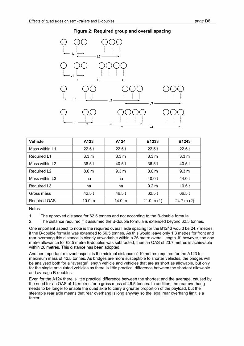
Effects of quad axles on semi-trailers and B-doubles page D6
Figure 2: Required group and overall spacing
Vehicle A123 A124 B1233 B1243
Mass within L1 22.5 t 22.5 t 22.5 t 22.5 t
Required L1 3.3 m 3.3 m 3.3 m 3.3 m
Mass within L2 36.5 t 40.5 t 36.5 t 40.5 t
Required L2 8.0 m 9.3 m 8.0 m 9.3 m
Mass within L3 na na 40.0 t 44.0 t
Required L3 na na 9.2 m 10.5 t
Gross mass 42.5 t 46.5 t 62.5 t 66.5 t
Required OAS 10.0 m 14.0 m 21.0 m (1) 24.7 m (2)
Notes:
1. The approved distance for 62.5 tonnes and not according to the B-double formula.
2. The distance required if it assumed the B-double formula is extended beyond 62.5 tonnes.
One important aspect to note is the required overall axle spacing for the B1243 would be 24.7 metres
if the B-double formula was extended to 66.5 tonnes. As this would leave only 1.3 metres for front and
rear overhang this distance is clearly unworkable within a 26 metre overall length. If, however, the one
metre allowance for 62.5 metre B-doubles was subtracted, then an OAS of 23.7 metres is achievable
within 26 metres. This distance has been adopted.
Another important relevant aspect is the minimal distance of 10 metres required for the A123 for
maximum mass of 42.5 tonnes. As bridges are more susceptible to shorter vehicles, the bridges will
be analysed both for a “average” length vehicle and vehicles that are as short as allowable, but only
for the single articulated vehicles as there is little practical difference between the shortest allowable
and average B-doubles.
Even for the A124 there is little practical difference between the shortest and the average, caused by
the need for an OAS of 14 metres for a gross mass of 46.5 tonnes. In addition, the rear overhang
needs to be longer to enable the quad axle to carry a greater proportion of the payload, but the
steerable rear axle means that rear overhang is long anyway so the legal rear overhang limit is a
factor.

Effects of quad axles on semi-trailers and B-doubles page D7
2.2. Vehicle type considerations
Different market sectors have different vehicle requirements and designs. A stock crate, a tanker, a
container vehicle, a curtain sided vehicle, a tipper, a car carrier and a refrigerated vehicle all have
different tare mass and mass distribution. Therefore, the vehicle layouts and tare masses are a fleet
average rather than typical vehicle types. The tare masses used are the same as used by the ATA for
their vehicle comparison calculation, the truck impact chart, except for the quad axle. Masses used are
given in Table 3.
Table 3: Tare and gross mass (tonnes)
Vehicle A123 A124 B1233 B1243
Tare steer 5.5 5.5 5.5 5.5
Gross steer 6.0 6.0 6.0 6.0
Tare drive 6.35 6.35 6.35 6.35
Gross drive 16.5 (17.0) 16.5 (17.0) 16.5 (17.0) 16.5 (17.0)
Tare lead trailer 6.5 7.9 6.5 7.9
Gross lead trailer 20.0 (22.5) 24.0 (27.0) 20.0 (22.5) 24.0 (27.0)
Tare rear trailer na na 5.2 5.2
Gross rear trailer na na 20.0 (22.5) 20.0 (22.5)
Note: figures in brackets are for HML
2.3. Vehicle loading considerations
The project requires consideration of vehicles at both GML and HML. For uniformly distributed loads,
the dimensions would need to change if legal axle loads were not to be exceeded on at least one of
the axle groups. In other words, one axle group would be underloaded and another overloaded if the
same vehicle dimensions were used for both GML and HML with uniformly distributed loads. However,
the same vehicle dimensions have been used both because that is a more logical approach and there
are many payloads that are not uniformly distributed.
Both of the single articulated vehicles (the A123 and A124) have been given the same load space in
the “average” length so as to provide a direct comparison between the different vehicles. Similarly, the
B-doubles (the B1233 and B1243) have the same load space.
2.4. Spacing within axle groups
As the bridge impacts are greater for smaller dimensions, spacing within axle groups has been set at
1.2 metres when the actual spacing could be 1.35 metres. It is considered that the shorter spacing will
have little practical effect on other impacts to be assessed.
2.5. Final vehicle dimensions
Main vehicle dimensions in the analysis used are given in Attachment 1.

Effects of quad axles on semi-trailers and B-doubles page D8
3. Bridge impacts
3.1. Methodology
Bridge effects were calculated in accordance with the methodology undertaken for the review of axle
spacing mass schedules above 42.5 tonnes (NRTC 1998). The effects of each of the eight vehicles
were calculated on bridges with both simply supported spans and bridges which are continuous for
live loads. Comparative bending moment effects of the eight vehicles identified in Table 2 were
calculated at two metre increments for spans from 10 to 50 metres.
In addition to these eight vehicles, single articulated vehicles (A123 and A124) were also assessed for
the shortest possible vehicles allowable under the bridge formula for such vehicles as outlined in
section 2 above.
After calculating the maximum positive and negative movements, comparison was made with MS18
design moments and the BEC7 allowances included. BEC allowances were determined by NAASRA
(the fore-runner to Austroads) for the Economics of Road Vehicle Limits Study (ERVL) in the 1970s.
They take into account that bridges were designed for loads significantly greater than the theoretical
design loads due to factors of safety built into the design process. The BEC allowances used in ERVL
were:
1 to 15 metre spans: 1.25;
16 to 29 metre spans: 1.25 up to 1.50; and
30 metres and over: 1.50.
MS18 design moments are those derived from the bridge design loads as a basis for bridge design in
the 1960s and early 1970s (then called H
20
S
16
44) prior to the introduction of T44 design loading.
To enable ready comparison of the effects on different spans, an ‘overstress factor’ was calculated,
being the bending moment caused by the vehicle divided by the MS18 design bending moment which
has been multiplied by the BEC allowance. It is generally accepted that overstress factors in excess of
1.2 should be avoided if possible and that vehicles causing overstress factors in excess of 1.1 should
not be allowed general access without investigation of individual bridges. When investigating and
developing bridge formulae, it is the aim that these overstress factors will not be exceeded.
The overstress factor is both a network assessment tool and a risk assessment tool that can be
applied to networks as a filter. An overstress factor exceeding 1.1 (or 1.2 for HML loads) does not
mean the vehicle being assessed cannot use a particular route or a particular bridge. The overstress
factor identifies bridge types and span lengths that should be investigated. The investigation would
then determine that there is a possible problem only if:
the bridge types and span lengths are present on a route; and
the bridges with these span lengths are MS18 or lower design standard.
If these two factors exist, an individual check on the bridge is carried out which can still pass the
bridge as satisfactory for the vehicle being assessed.
3.2. Results of the Analysis – Simply Supported Spans
Figure 3 shows the overstress factors for the short single articulated vehicles on simply supported
spans. In no case does the overstress factor exceed 1. However, the individual axle group loads
provide the maximum moment for the shorter spans and this issue is discussed later.
7
BEC stands for Bridge Engineering Committee, a standing committee under NAASRA
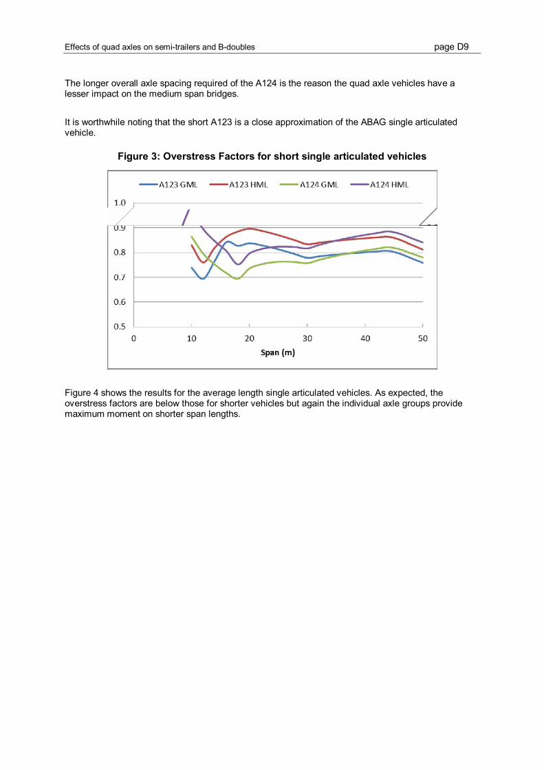
Effects of quad axles on semi-trailers and B-doubles page D9
The longer overall axle spacing required of the A124 is the reason the quad axle vehicles have a
lesser impact on the medium span bridges.
It is worthwhile noting that the short A123 is a close approximation of the ABAG single articulated
vehicle.
Figure 3: Overstress Factors for short single articulated vehicles
Figure 4 shows the results for the average length single articulated vehicles. As expected, the
overstress factors are below those for shorter vehicles but again the individual axle groups provide
maximum moment on shorter span lengths.

Effects of quad axles on semi-trailers and B-doubles page D10
Figure 4: Overstress Factors for average length articulated vehicles
Figure 5 shows the overstress factors for the B1233 and the B1243 at both GML and HML. The
maximum OSF for the B1243 at HML is 1.16 and at GML is 1.06, both below the target values of 1.2
and 1.1 respectively. As expected, the individual groups provide the maximum moment for the short
spans.
Figure 5: Overstress Factors for B-doubles
Because the overstress factor method was originally applied to axle spacing mass schedule and
therefore groups of vehicles, there could be some doubt about the application of the overstress factor
method to individual axle groups. Colosimo (2011) suggested that T44 loading is a benchmark for
acceptability:
Traditionally the structures group (represented by the decisions of past experts in this
field both in Victoria and some other states), have accepted that the T44 vehicle is the
most reliable design vehicle, for load rating the older short span (and timber) bridges.

Effects of quad axles on semi-trailers and B-doubles page D11
A comparison has been made therefore with T44 design moments as shown in Figure 6. The GML
quad-axle moments are up to 12% greater than T44 loading.
Figure 6: Comparison of T44 loads with GML loads (simple spans)
3.3. Results of the Analysis - Continuous Spans
For spans that are continuous for live load, the major impact arises due to the negative (or hogging)
moment over a support or pier.
The results for the short articulated vehicles are given in Figure 7 which shows that the quad axle
articulated vehicle at HML is very close to the limit of 1.2 for HML for 12 metre spans and 1.1 for GML
also at 12 metre spans but other spans are of no concern.
Figure 7: Overstress Factors for short articulated vehicles
Similarly, for the average length vehicles (Figure 8), the quad axle comes close to the limits at 14
metre spans but other spans are again of no concern.

Effects of quad axles on semi-trailers and B-doubles page D12
Figure 8: Overstress factors for average length articulated vehicles
The results for the different B-doubles are shown in Figure 9. These results show that the 1.2 OSF for
HML routes is exceeded for spans of 12 to 14 metres and the 1.1 OSF for GML is exceeded by the
B1243 for 10 to 16 metre spans.
Figure 9: Overstress Factors for B-doubles
Finally, the overstress factors for the B1243 vehicles are compared to the overstress factors for the
ABAG B-doubles in Figure 10. It can be seen that the factors are very similar apart from the 10 to 12
metre spans.

Effects of quad axles on semi-trailers and B-doubles page D13
Figure 10: Overstress Factors for the B1243 and ABAG B-doubles

Effects of quad axles on semi-trailers and B-doubles page D14
4. Pavement impacts
4.1. Introduction
The relative effects on pavements of the increased use of quad axle in lieu of triaxles were calculated
for a fixed freight task. Vehicles considered were single articulated vehicles and B-doubles, with an
A124 used in place of an A123 and a B1243 used in place of a B1233.
In addition, different take-up estimates of quad axle vehicles were used to estimate an overall impact
on pavements.
Yeo et al (2007) concluded that the reference load for a quad axle was 22.5 tonnes and this load has
been used in the calculations for this project.
Only GML loads have been considered here, but it is worthy of noting that Yeo et al (2007) concluded
that “the equivalent HML load on the quad axle compared to a triaxle group of 22.5 tonne was 27
tonne.”
4.2. Relative pavement wear
To calculate the relevant pavement wear, calculations were undertaken for a constant freight task of
10,000 tonnes. Reference loads used were (from Yeo 2007):
Steer axle: 5.4 tonnes
Drive tandem: 13.8 tonnes
Triaxle group: 18.5 tonnes
Quadaxle group: 22.5 tonnes
Results are given in Table 4. It can be seen that the increased use of quad axle vehicles will reduce
pavement wear by 11% for an A124 and by 7.9% for a B1243.
Table 4: Relative pavement wear for a constant freight task of 10,000 tonnes
Vehicle A123 A124 B1233 B1243
Gross mass (tonnes) 42.5 46.5 62.5 66.5
Tare mass (tonnes) 18.35 19.75 24.85 26.1
Payload (tonnes) 24.15 26.75 37.65 40.4
SARs per laden trip 4.93 4.86 6.30 6.23
Trips per 10,000 tonne task 414 374 266 248
Total SARS 2043 1818 1673 1542
Relativity 0 -11.0% 0 -7.9%
Note: SARs are Standard Axle Repetitions
When, however, the quad axle vehicles carried the same payload as the triaxle vehicles the road wear
savings would be in the order of 25%. This is likely to occur early in the transition period when regular
orders are uploaded onto quad axle vehicles that have replaced triaxle vehicles
Effects of quad axles on semi-trailers and B-doubles page D15
4.3. General savings in road wear
The level of annual savings in road wear will depend on a range of factors affecting the number of
present triaxle vehicles that would be replaced with quad axle vehicles.
From a technical viewpoint, some commodities could be difficult to load without a triaxle group on the
prime mover for proper load distribution but there would be little mass advantage in that configuration.
Other disincentives would arise if charges were seen as too high or if IAP were imposed. Ability to
utilise the additional payload is always an issue when additional cost for equipment is required, and
this aspect will become more important as the density of freight overall decreases in the future.
Given these circumstances, it is estimated that around 10% of the present 6-axle articulated and 9-
axle B-double fleet would convert to quad axle vehicles. The conversion could be as low as 5% if there
were significant disincentives or as high as 20% if all factors were favorable and conversion costs
relatively small.
The present freight task undertaken by 6 axle articulated vehicles is about 45,000 million tonne-
kilometres per year and by 9 axle B-doubles about 60,000 million tonne-kilometres per year. Based on
the above conversion estimates and a general road wear cost of the region of 4 cents per ESA
kilometre, the road wear savings would be in the order of $7 million to $10 million annually.

Effects of quad axles on semi-trailers and B-doubles page D16
5. Swept path impacts
5.1. Methodology
Swept path impacts were determined by using the TERNZ version Yaw Roll multi-body simulation
software developed at the University of Michigan Transportation Research Institute (Gillespie and
MacAdam, 1982) to simulate the vehicles through a 12.5m radius low speed turn undertaken at 5km/h.
This is the standard low speed turning manoeuvre specified in the PBS methodology (NTC, 2008).
The swept path is defined as the maximum width between the paths of the innermost and outermost
parts of the vehicle during this manoeuvre.
For the purposes of this analysis, it was assumed that the front of the prime movers are square and
2.4m wide at the front most part of the vehicle as defined by the front overhang (FO) value in
Attachment 1. For some prime movers with curved fronts this is a conservative assumption but as we
use the same assumption for all of the vehicles analysed it provides a fair comparison.
In addition to swept path, there are three other performance measures used in the PBS system that
are evaluated during the low speed turning manoeuvre. These are tail swing (TS), frontal swing (FS)
and steer tyre friction demand (STFD). At the start of the turn the rear of the vehicle swings out in the
opposite direction to the turn. The maximum amount by which the rear corner of the vehicle crosses
the original straight ahead path of the vehicle is called the tail swing. As the vehicle proceeds through
the turn the path of the front outer corner of the vehicle often passes outside the path of the outer
edge of the steer tyre. The maximum offset between these two paths is called the frontal swing. With
multi-axle groups executing low speed turns the geometry means that at least some tyres in the group
are operating with slip angles. This results in some lateral force which must be balanced by lateral
forces at the steer tyres. The amount of lateral force that can be generated at the steer tyres is
potentially limited by the amount of friction available. Thus STFD is the percentage of the available
steer force that is required for the vehicle to execute the turn. This measure depends primarily on the
prime mover wheelbase, the number of prime mover rear axles and the weight they are loaded to.
There is a small effect from the trailer(s) but generally with semi-trailers and B-doubles the trailer
coupling point on the prime mover is relatively close to the rear axis and thus the trailer(s) have only a
small effect on the steering forces required.
5.2. Swept Path Results
The low speed turning performance results for the eight vehicles under consideration are shown in
Table 5. The main measure of interest is the low speed swept path but the other measures are shown
for completeness. The PBS limits for low speed swept path are 7.4m for level 1, 8.7m for level 2 and
10.6m for level 3. Thus the B1243 combinations as specified do not achieve the level 2 PBS standard.
The reason for this is the vehicle’s geometry. However, it is possible to specify an alternative geometry
for this vehicle which meets all the axle spacing requirements as specified in Figure 2 and achieves
the level 2 PBS requirement for low speed swept path. The dimensions of this alternative B1243
vehicle are shown in Figure 11 its performance measure results are in the last row of Table 5.
Table 5. Low speed turning performance results.
Vehicle
Low Speed
Swept Path (m)
Tail Swing
(m)
Frontal Swing
(m)
Steer Tyre Friction
Demand (%)
A123 GML 6.90 0.06 0.55 34
A123 HML 6.90 0.06 0.55 34
A124 GML 6.50 0.12 0.55 33

Effects of quad axles on semi-trailers and B-doubles page D17
A124 HML 6.49 0.12 0.55 33
B1233 GML 8.54 0.04 0.65 33
B1233 HML 8.52 0.04 0.65 34
B1243 GML 9.00 0.08 0.65 35
B1243 HML 9.00 0.08 0.65 34
B1243 GML alt 8.69 0.09 0.65 34
Figure 11: Alternative Vehicle 6: 10 axle B-double (B1243) – (GML)
FO F KPL(l) X2 Y2 KPL(2) RO OAS OAL Gross
1.7 4.0 -0.2 5.85 5.95 0.65 1.95 23.7 26.0 66.5
The key points of the low speed turning analysis are:
The quad axle semi-trailers (A124) have less low speed swept widths than the standard tri-axle
semi-trailers (A123). This is because the trailers have a smaller s-dimension. The prime movers
are identical for both configurations.
The quad axle semi-trailers have greater tail swing than the tri-axle semi-trailers . As both semi-
trailers have the same deck length and the same front overhang, having a smaller s-dimension
results in a larger rear overhang and thus the reduction in swept width is achieved at the
expense of an increase in tail swing. The Level 1 PBS limit for tail swing is a maximum of 0.3m.
For all the vehicles the tail swing is much less than this limit and is not a problem.
The B-doubles with the quad-axle first trailer (B1243) have greater low speed swept widths than
the standard (B1233) B-doubles. This is because the s-dimension of the second trailer is
substantially greater for the B1243 compared to the B1233. The prime mover and the s-
dimension of the first trailer are identical for both configurations.
It is necessary to increase the total axle spread for the B1243 compared to the B1233 in order
to meet the bridge requirements for the additional weight capacity. However, there are
alternative ways of achieving this with better low speed swept width performance. This is
illustrated with the alternative design geometry shown above.
The front overhang on the prime movers used for the semi-trailer vehicles is 0.1m less than that
used for the B-double vehicles. As a result the frontal swing is greater for the B-doubles than for
the semi-trailers. All the semi-trailer vehicles have the same frontal swing and all the B-double
vehicles have the same frontal swing. Thus the trailer configuration and weight has no
measurable effect (to the nearest 5mm) on frontal swing.
There is a very small weight effect on low speed swept path with heavier vehicles having a
slightly lesser swept width. The reason for this is that the tyre properties are non-linear and thus
for a given slip angle, the cornering force generated is not exactly proportional to the vertical
load.

Effects of quad axles on semi-trailers and B-doubles page D18
The steer tyre friction demand is approximately the same for all the vehicles and is well within
acceptable limits. All vehicles used essentially the same prime mover apart from the difference
in front overhang. Thus with the relatively small fifth wheel offset on the prime mover, the trailers
have very little effect on the STFD.

Effects of quad axles on semi-trailers and B-doubles page D19
6. Stability impacts
6.1. Introduction
The proposed quad axle combinations are designed to operate at higher weights than the tri-axle
alternatives and thus it was anticipated that this would affect the rollover stability of the vehicles. There
are, in fact, two competing effects. The quad-axle vehicles have the same deck length as the tri-axle
alternatives and thus, if all of the deck area is utilized, a greater payload will result in a higher payload.
This will increase the height of the centre of gravity of the vehicle which will, in turn, reduce its rollover
stability. On the other hand, the rollover stability of a vehicle is also affected by the roll stiffness of the
suspension. The quad axle vehicles by virtue of the additional axle have greater roll stiffness which
would tend to improve the rollover stability. This analysis is to determine the extent to which these two
effects cancel each other out.
In the PBS system the rollover stability of a vehicle is characterised by a measure called Static
Rollover Threshold (SRT). SRT is the maximum lateral acceleration that the vehicle can withstand
before all the wheels, except the steer axle, lift off the ground. In this analysis the SRT was
determined by computer simulation using the Yaw-Roll multibody simulation package and the
methodology specified in the PBS Rules (NTC, 2008).
6.2. Assumptions
The key vehicle parameters influencing SRT are the height of the centre of gravity, the tyre track width
and the roll stiffness of the suspension. Thus for this comparison it is important to select the vehicle
parameters carefully.
The following assumptions were made:
All vehicles were fitted with the same 11R22.5 tyres
For all combinations the prime mover was identical, apart from the difference in front overhang
between the semi-trailer vehicle and the B-double vehicle. This front overhang has no effect on
rollover stability.
All trailer axles were fitted with the same air suspension.
The vehicle tare and gross weights were as specified in Table 3
The load deck was assumed to be 1.4m above the ground and a uniform density load with a
density of 400 kg/m
3
was applied to the whole deck area. For some vehicles
an adjustment to
the longitudinal position of the payload CoG was necessary to achieve the correct axle weights.
With the B-doubles the payload was split between the two trailers in proportion to the deck
length. Thus the payload height was the same in each of the two trailers.
The deck height and the payload density are somewhat arbitrary but are identical for all vehicles.
Changing these would change the results but the relativities between vehicles will be substantially
the same.
6.3. Stability Results
The SRT results for the nine vehicle configurations analysed are shown in Table 6. These can be
summarized as follows:
As expected the HML vehicles all have a reduced rollover stability compared to the GML
vehicles of the same configuration.

Effects of quad axles on semi-trailers and B-doubles page D20
The quad-axle semi-trailers have the same rollover stability as the comparable tri-axle semi-
trailer. Thus the additional roll stiffness provided by the additional axle offsets the effect of the
increase in payload CoG height.
The quad-axle B-doubles have a slightly reduced rollover stiffness compared to the tri-axle
vehicles they would replace. The difference is very small (0.01g).
The alternative geometry B1243 vehicle has the same rollover stability as the reference B1243
vehicle. Thus changing the geometry did not adversely affect rollover stability.
Table 6. Rollover stability results.
Vehicle SRT (g)
A123_GML 0.43
A123_HML 0.39
A124_GML 0.43
A124_HML 0.39
B1233_GML 0.40
B1233_HML 0.37
B1243_GML 0.39
B1243_HML 0.36
B1243_GML_alt 0.39

Effects of quad axles on semi-trailers and B-doubles page D21
7. Other issues
7.1. The bridge formulae for B-doubles
The present bridge formulae for B-doubles as described in section 2 does not extend beyond 62.5
tonnes, viz
3L + 12.5 to 46.5 tonnes; then
1.5L + 29.5 from 46.5 tonnes to 62.5 tonnes.
Also as noted in section 2, the overall axle spacing required to achieve 62.5 tonnes is only 21 metres
under present requirements.
To accommodate an increase to 66.5 tonnes for a B1243 at GML, modifications will be necessary.
One option would be to adopt the following formulae:
3L + 12.5 to 46.5 tonnes; then
1.5L + 29.5 from 46.5 tonnes to 61 tonnes; then
1.5L + 31 from 61 tonnes to 66.5 tonnes.
Although there is a discontinuity in these formulae, as shown in Figure 12, these formulae would be
simplest without a major project to assess possible new formulae
Figure 12: Illustration of possible bridge formulae

Effects of quad axles on semi-trailers and B-doubles page D22
7.2. Conditions for operation of quad axles
The national quad axle policy (NTC 2007) includes at section 3.1 (h):
The quad axle group must be fitted with either:
1. a steerable rear axle with no less than ±12 degrees of steering articulation and an
effective automatic centring mechanism; or
2. another system that is acceptable to the registration authority as proven to be
effective in mitigating road scrubbing impacts.
The present PBS requirement for quad axles, PBS clause A2.3, stipulates:
for axle groups with three or more axles and a spread of greater than 3.2 metres, all
axles beyond the 3.2 metre spread must be steerable.
However, the only reference to quad axles in the Australian Vehicles Standards Rules (AVSRs) is the
definition as follows
quad axle group means a group of 4 axles in which the horizontal distance between
the centre lines of the outermost axles is over 3.2 metres, but not over 4.9 metres.
If quad axles are to be adopted more widely, it would be necessary to be more formal about
steerability requirements than simply stated in the quad axle policy. One option would be to insert the
requirements of the quad axle policy into the AVSRs.
However, care would need to be taken that any steering requirements did not apply to quad axle on
low loaders who have traditionally been permitted access without the need for steerability.
7.3. Other PBS comparisons
To assess whether or not there are any other performance issues a number of other performance
measures were evaluated.
The performance measures evaluated were:
Rearward Amplification;
High speed transient offtracking (HSTO)
Yaw Damping Ratio
High Speed Steady Offtracking
The results of these evaluations are listed in Table 7.

Effects of quad axles on semi-trailers and B-doubles page D23
Table 7: Additional PBS results
Vehicle
Rearward
Amplification
High Speed
Transient
Offtracking (m)
Yaw
Damping
Ratio
High Speed
Steady
Offtracking (m)
A123_GML 1.09 0.17 0.56 0.25
A123_HML 1.13 0.19 0.54 0.26
A124_GML 1.08 0.19 0.65 0.30
A124_HML 1.11 0.23 0.63 0.34
B1233_GML 0.96 0.28 0.44 0.39
B1233_HML 1.01 0.31 0.45 0.42
B1243_GML 0.90 0.25 0.50 0.42
B1243_HML 0.94 0.29 0.50 0.49
B1243_GML_alt 0.95 0.29 0.47 0.49
Rearward amplification (RA) and high speed transient offtracking (HSTO) are both evaluated using a
high speed lane change manoeuvre. This is specified in the PBS system rules (NTC, 2008). Both
semi-trailer combinations and B-doubles are known to have good dynamic performance and this is
borne out of the results.
The maximum allowable RA is 5.7 x SRT. The minimum allowable SRT is 0.35g and thus the lowest
RA limit is 2. All of the vehicles have RA values well below this.
The maximum allowable HSTO in the PBS system is 0.6m for level 1 and 0.8m for level 2. The worst
case vehicle in our set has an HSTO of just over 0.3m.
Yaw damping ratio (YDR) reflects the rate at which trailer oscillations decay following a pulse steer
input. The PBS system requires a minimum level of 0.15. All of the vehicles analysed are considerably
better than this.
Finally high speed offtracking is a measure of how far the trailers track outboard of the prime mover
during a steady speed turn. The manoeuvre used to evaluate this measure is a 393m radius turn
negotiated at 100km/h which generates a lateral acceleration of 0.2g. This measure is not part of the
Australian PBS system but it is used extensively in Canada and New Zealand. The research studies
underpinning the Australian PBS system showed the HSO and Tracking Ability in a Straight Path
(TASP) were strongly correlated and it was decided to include TASP in the PBS system in place of
HSO. The relationship between TASP and HSO was found to be: TASP = vehicle width + 0.3153 x
HSO + 0.0225 (Prem et al, 2002). On this basis the worst case HSO corresponds to a TASP value of
2.68m which would be reported as 2.7m. This is well below the level 1 PBS upper limit of 2.9m.
In general there is a trade-off between low speed and high speed turning performance (Fancher and
Winkler, 2007). A vehicle that has better low speed turning performance is generally more dynamically
active and has poorer high speed dynamic performance. This is illustrated to a limited extent by the
alternative geometry vehicle which has better low speed turning performance than the reference
B1243 GML vehicle but slight worse high speed dynamics with higher RA and HSTO values.
However, the degradation in high speed performance is very small and its performance is still
excellent.

Effects of quad axles on semi-trailers and B-doubles page D24
8. Discussion and Conclusions
For bridges with continuous spans, there are some concerns that some bridges in the 10 to 16 metre
range might be overloaded with quad axles at 24 tonnes. However, the most concerns arise with
simply supported bridges with spans between 4 and 9 metres. With these bridges, T44 design
moments are exceeded with a 24 tonne quad axle load.
It is not known for certain how many bridges will be affected. The only publically available bridge
inventory information is from the Mass Limits Review undertaken in the mid 1990s (NTRC 1996).
Some salient points from the bridge information gathered at that time are:
information on nearly 26,000 bridges was reported:
37% of these bridges had spans of between 5 and 9 metres; and
91% of the bridges had simply supported spans.
The data collected related primarily to main roads and little data related to bridges on local roads,
which are likely to be of similar proportions.
Road wear would be reduced if quad axles were permitted. SARS for the individual quad-axle group at
24 tonnes are 5% lower than for a triaxle at 20 tonnes, leading to savings in the order of 11% for
single articulated vehicles and about 8% for B-doubles. Overall, savings could be in the order of $7
million to $10 million annually.
Of interest is that the ARRB report that examined the general use of quad axles, Yeo et al (2007),
concluded that “the equivalent HML load on the quad axle compared to a triaxle group of 22.5 tonne
was 27 tonne.”
The swept path of single articulated vehicles would probably decrease as the rear quad-axle group
would need to be closer to the drive axle groups for loading purposes, reducing the S-dimension and
hence reducing low speed offtracking. On the other hand, the B-doubles have a greater swept path
due to the need to spread out axle groups to meet the bridge formula. The quad-axle vehicles in the
analysis did not meet Level 2 PBS but it is possible to build a B-double with a quad-axle in the centre
that meets Level 2.
The replacement of the triaxle with a quad axle resulted in very little impact on roll stability. The
additional roll stiffness of the extra axle offsets the increase in the height of the payload and the
associated increase in centre of gravity height. The roll stability of the single articulated vehicles was
identical while for the B-doubles the difference was only 0.01g.
Overall therefore, it is concluded that the only constraint on the replacement of a triaxle with a quad-
axle appears to be the impacts on short span simply supported bridges.
However, the impacts may not be as great as indicated by the analysis. Low loaders with a gross
mass of 49.5 tonnes and a triaxle load of 25 tonnes are permitted wide network access. Similarly, a
low loader fitted with a quad axle is permitted 30 tonnes. Colosimo (2011) states that live load factors
of 2 are used for assessment of general access vehicles. In other words, a bridge must be capable of
supporting a load that is twice the legal load to cater for a range of factors including the occasional
overloaded vehicle. Reduced live load factors are applied to low loaders carrying indivisible loads.

Effects of quad axles on semi-trailers and B-doubles page D25
It is suggested therefore that road authorities be requested to report on the impacts of quad axles at
24 tonnes for general access for bridges under their control and if the impacts are manageable.
Consideration could be given to allowing quad axles at 24 tonnes on selected routes or to allowing
quad axles under CML conditions. Lower live load factors should apply under CML conditions.
If quad axles are to replace triaxles, there would be a need to modify the bridge formulae applicable to
B-doubles and formalise some conditions for operation for quad axles such as minimum steerability
requirements.

Effects of quad axles on semi-trailers and B-doubles page D26
References
Colosimo, Vince (2011). Load Rating Bridge Structures –VicRoads Practice. 2011 Austroads Bridge
Conference.
Fancher, PS, RD Ervin, CB Winkler and TD Gillespie (1986). A factbook of the mechanical properties
of the components for single-unit and articulated heavy trucks. Washington, DC: US Department of
Transportation. .
Fancher, P. and Winkler, C. (2007). Directional performance issues in evaluation and design of
articulated heavy vehicles, Vehicle System Dynamics, 45(7-8), 607-647.
Gillespie, TD and MacAdam, CC (1982). Constant velocity yaw/roll program user’s manual. The
University of Michigan Transportation Research Institute. .
NRTC (1998). Review of Axle Spacing Mass Schedules for Heavy Vehicles above 42.5 tonnes.
Prepared by Pearsons Transport Resource Centre for Austroads and the National Road Transport
Commission.
NTC (2008). Performance Based Standards Scheme, The Standards and Vehicle Assessment Rules.
Melbourne: National Transport Commission.
Prem, H, J de Pont, B Pearson and J McLean, (2002). Performance characteristics of the Australian
heavy vehicle fleet (performance based standards - NRTC/Austroads project A3 and A4), working
paper. Melbourne: National Road Transport Commission.
Yeo et al (2007). The relative damaging effects of quad axles and triaxles. Richard Yeo, Siew Leng
Koh, Will Hore-Lacey and Trevor Uebergang. ARRB Group Ltd Research Report ARR 369.

Effects of quad axles on semi-trailers and B-doubles page D27
Attachment 1: Vehicle Dimensions
Vehicle 1: 6 axle articulated vehicle (A123) - GML
Length FO A KPL B S
dim
RO OAS OAL Gross
Short 1.3 2.4 -0.2 4.4 5.8 2.1 10.4 12.6 42.5
Average 1.5 3.9 -0.2 7.4 9.4 2.9 14.9 18.1 42.5
Vehicle 2: 7 axle articulated vehicle (A124) – (GML)
Length FO C KPL D S
dim
RO OAS OAL Gross
Short 1.3 3.0 -0.2 6.2 8.2 3.4 14.0 16.3 46.5
Average 1.5 3.9 -0.2 6.6 8.6 3.7 15.3 18.1 46.5
Vehicle 3: 6 axle articulated vehicle (A123) - HML
Dimensions as for Vehicle 1, gross mass 45.5 tonnes
Vehicle 4: 7 axle articulated vehicle (A124) – (HML)

Effects of quad axles on semi-trailers and B-doubles page D28
Dimensions as for Vehicle 2, gross mass 50.0 tonnes
Vehicle 5: 9 axle B-double (B1233) – (GML)
FO E KPL(l) X1 Y1 KPL(2) RO OAS OAL Gross
1.7 4.0 -0.2 5.9 6.6 0.5 2.8 22.5 25.8 62.5
Vehicle 6: 10 axle B-double (B1243) – (GML)
FO F KPL(l) X2 Y2 KPL(2) RO OAS OAL Gross
1.7 4.0 -0.2 5.9 6.6 0.2 1.8 23.7 26.0 66.5
Vehicle 7: 9 axle B-double (B1233) – (HML)
Dimensions as for Vehicle 5, gross mass 68.0 tonnes
Vehicle 8: 10 axle B-double (B1243) – (HML)

Effects of quad axles on semi-trailers and B-doubles page D29
Dimensions as for Vehicle 6, gross mass 72.5 tonnes
Other dimensions
Vehicle A123 A124 B1233 B1243
Length of lead trailer 13.7 m 13.7 m 7.0 m 7.0 m
Length of rear trailer na na 12.5 m 12.5 m
Trailer front to king pin (lead) 1.4 m 1.4 m 1.4 m 1.4 m
Trailer front to king pin (rear) na na 1.2 m 1.3 m