review of recent experience ... - steel-renovation.org 4.1.1 and 4.2 review of recent... · corus...
TRANSCRIPT

3
Corus Research, Development & Technology Swinden Technology Centre ICA
Moorgate Rotherham South Yorkshire S60 3AR
United Kingdom T 01709825537
Reference Source no.
Project number 956840
Date of issue 18 July 2008
Security Code
Review of recent experience throughout Europe on upgrading of roof systems in steel including creation of habitable spaces
ROBUST Project: WP 4.1 and 4.2
Author(s): Israel Adetunji

DRAFT
Reference Source no.
Initial circulation list <<Name>> <<Name>> <<Name>> <<Name>> <<Name>> <<Name>> <<Feel free to add or delete columns in the table above>> <<Careful, NEVER use textcolumns here! Textcolumns use section breaks, and sections can offset the page numbering!>> <<Type the initial list. Some people on the circulation list may not require a full copy of the report, in this instance a summary page only, may be provided. Recipients of a summary page will be indicated by an asterisk (*) on the circulation list. Colour copies may also be restricted. Recipients of colour copies will be indicated by a plus (+) on the circulation list.>>
Security Code
Care has been taken to ensure that the contents of this report are accurate, but Corus UK Limited and affiliates do not acceptresponsibility for errors or for information that is found to be misleading. Suggestions for or descriptions of the use of products orthe application of products or methods of working are for information purposes only, and Corus UK Limited and affiliates acceptno liability in respect thereof. Before using information or products supplied or manufactured by Corus UK Limited or affiliatesthe user should make certain that they are suitable for their purpose. For further information or assistance, please contact Corus UK Limited. COPYRIGHT AND DESIGN RIGHT - © 2008 - CORUS UK Limited

DRAFT
Reference Source no.
Contents Page
1. 1 Introduction
2. 1 Systems Overview2.1 2 Overview of Systems Reviewed
3. 3 Steel Roofing Systems3.1 3 Hi-Point3.2 5 Gus Truss / Nu Truss3.3 7 Dibsa3.4 9 Capella Pin Truss3.5 11 Capella Vierendeel Truss System3.6 12 AyrTruss3.7 13 Ashjack3.8 15 Fusion Building Solutions3.9 17 Rosette3.10 19 Metsec Trusses3.11 21 Cover Structure
4. 23 Other Products / Systems of Interest4.1 23 Freeframe4.2 24 AyrFrame4.3 25 Moment Frame4.4 28 Opstalan4.5 29 Lett-Tak4.6 30 Smartroof4.7 31 Europe TwinTile / Kingspan Panel Systems4.8 32 Cool Roof Tiles4.9 33 Urban Roof
5. 34 Related Research in Europe5.1 34 Prefabricated Systems for Low Energy Renovation of Residential Buildings
6. 36 Conclusion and Recommendation
Reference 38

2
DRAFT
Reference Source no.
Summary Review of recent experience throughout Europe on upgrading of roof systems in steel including creation of habitable spaces ROBUST Project: WP 4.1 and 4.2 Author(s): Israel Adetunji Reviewer(s): Date of issue: 13 May 2010 Version no: Security Code: A study into the use of lightweight steel roof systems suitable for new build and refurbishment of existing roofs has been conducted. Systems, both steel intensive and other materials, capable of providing a habitable space within the roof void have been included to enhance the understanding of the state of the art within Europe and to facilitate knowledge transfer. Similarly, the study briefly touched on a highly relevant and ongoing research project focusing on prefabricated systems for low energy renovation of residential buildings for completeness. The need for this investigation has arisen as part of the RFCS funded ROBUST project to further develop the use of steel intensive solution for refurbishment of existing buildings.
The breadth of the systems reviewed (Table 1) can be broadly categorised as: Modularised lightweight steel Panelised lightweight steel trusses Panelised composite lightweight steel panel or structural insulated panel (SIP) Moment resisting lightweight steel frame Novel roof tile/profile systems
The main findings of the review were that the majority of the steel intensive solutions in the market are mainly geared toward new build and refurbishment of existing building in terms of over roofing and conversion of flat-to-pitch roofs. These systems are mostly panelised lightweight steel trusses. Only two of the systems reviewed are prefabricated modular systems (Hi-Point and AyrFrame). The configurations and spacing of these trusses prohibit the provision of a room-in-roof solution. There is a need for market research into the reasons for sparse availability of steel systems for creation of habitable roof for refurbishment application. Other non-truss systems have merits in terms of creating a habitable space for refurbishment. However they are generally disadvantaged by the spans they offer. There are opportunities for knowledge transfer in the use of composite timber cross walls for creating habitable roof. Concerning relevant research project, collaborative activity is strongly recommended with the Annex 50 research project focusing on “Prefabricated systems for low Corus Research, Development & Technology Swinden Technology Centre ICA
Moorgate Rotherham South Yorkshire S60 3AR
United Kingdom

DRAFT DRAFT
Reference Source no.
energy renovation of residential buildings (covering roof, HAV, Solar and façade systems)”. Customer: RFCS Programme manager:Simon Vaughan Approved by: Samir Boudjabeur

DRAFT DRAFT
Reference Source no.
Review of recent experience throughout Europe on upgrading of roof systems in steel including creation of habitable spaces
1. Introduction
The aim of this report is to review recent experience throughout Europe on upgrading roof systems in steel including creation of habitable spaces. In light of this, the report investigates the methods and lightweight steel systems currently available for roof refurbishment, over-roofing, and creating a room-in-roof. This scope is extended to cover systems that offer the conversion of flat roofs to pitch roofs in order to provide a holistic appraisal of the breadth of options available when considering the improvement/upgrading of existing buildings. The report provides a brief overview of each of the system in terms of application, product and technical description, methods of assembly, types of finishes, suitability and examples of case studies (Section 3). A total of fourteen steel intensive roof systems and two steel roof profile/tile systems are covered. In addition, three timber systems which demonstrate a novel approach to habitable roof spaces are documented for the purpose of knowledge transfer (Section 4). An ongoing research project focusing on prefabricated systems for low energy renovation of residential buildings is included for the purpose of collaboration (section 5). Finally, conclusions and recommendations are presented in the last section (section 6).
2. Systems Overview
The general systems for over roofing and creating habitable space are prefabricated 2D panelised or 3D modularised systems. The current market place for lightweight steel roof systems can be described as a developing market that has come about through the extensive use of lightweight steel wall framing systems. For this reason the technologies utilised in prefabricated roof systems such as the fixing and forming methods can be directly related to existing technology. The UK has recently seen a host of refurbishment projects that have utilised the advances in lightweight steel technology to design, fabricate and install pitched roofs to aging flat roofs. The creation of a habitable space within roof voids has historically been achieved by retrofitting insulation and plasterboard to traditional timber pitched roofs, in effect converting a cold roof to a warm roof. In view of this, the ability to create a warm roof using prefabricated lightweight steel sections for new build and refurbishment must not been overlooked by manufacturers and roofing suppliers. A list of the systems reviewed is presented in Table 1. The breadth of the systems covered herein can be broadly categorised as:
Modularised lightweight steel trusses Panelised lightweight steel trusses Panelised composite lightweight steel panel or structural insulated panel (SIP) Moment resisting lightweight steel frame Novel roof tile/profile systems
Page 1 of 37

DRAFT DRAFT
Reference Source no.
2.1 Overview of Systems Reviewed 2.1 Overview of Systems Reviewed
Table 1: Lists of roofing systems reviewed Table 1: Lists of roofing systems reviewed Application Application Suitability Suitability System
Name
Company Type Country Feature/
differentiator
Hi-Point Corus Plc UK Fully assembled in
factory or at ground
level, lifted onto roof
Offsite x x
x x
Gus Truss/
NuTruss
Gus Truss
Nucon Steel
Truss USA
Finland
Adjustable column
splice. Unique profile
section
Onsite x x x x
Dibsa Dibsa
Structures
Truss UK Top-hat section
On-/
Offsite
x x
x x
Capella Pin
Truss System
Kingspan Truss UK On-site adjustability
Onsite x x x x
Capella
Vierendeel
Truss System
Kingspan Truss UK Spans up to 30m Onsite x x
x x
AyrTruss Ayrshire Steel
Framing
Truss UK Welded,
off-site manufacture.
Offsite x x x x
AshJack Ash and Lacy
Building
Systems
Truss UK Adaptable system
Offsite x x
x x
Fusion
Building
Solutions
Fusion
Building
Solutions
Truss UK Bespoke sections
Offsite x x
Rosette Rosette
Systems Ltd
Truss Finland Bespoke connection
system
Offsite x
x
Metsec
Trusses
Metsec Plc Truss UK Long span up to 34m
Onsite x x x x x
Cover
Structure
Cover
Structure
Truss UK Flat-to-pitch
conversation
Offsite x x x x
Freeframe Banro
Sections Ltd
Truss UK Automated system
Offsite x
AyrFrame Ayehire Steel UK Welded, Offsite x x x x x
MomentFrame Ayehire Steel UK Bespoke connection Onsite x x x x
Opstalan * Opstalan BV Panel Nether-
lands
Panelised system
Offsite x x
x
x
Lett-Tak * Lett-Tak Truss/
Panel
Norway Hybrid truss/
panelised steel system
Onsite x x
SmartRoof * SmartRoof Ltd Panel UK Timber roof.
Room-in-roof
Onsite x x x x
TwinTile * Europe
TwinTile
Steel
tile
Belgium
UK
Novel use of steel to
mimic traditional tiles
Onsite x x x
x
x x
Cool Roof /
Urban Roof
Corus Plc
Steel
profile
USA
UK
Reduce heat Onsite x x x x x x
Onsite/
Indus
trial
Room
in roof Modular
Resid
ential
Comm
ercial
Over
roofing
Offsite New
build
Modular
Note: * = Systems that are somewhat disparate to the aims of ROBUST. However, they are included in this report
in order to highlight new or transferable technologies from outside the light weight steel construction sector.
Page 2 of 37
DRAFT DRAFT
Reference Source no.
3. Steel Roofing Systems 3. Steel Roofing Systems
This section provides a brief overview of the roofing systems (see Table 1) in terms of application, technical description, methods of assembly, types of finishes, suitability for habitable space and examples of case studies.
This section provides a brief overview of the roofing systems (see Table 1) in terms of application, technical description, methods of assembly, types of finishes, suitability for habitable space and examples of case studies.
3.1 Hi-Point 3.1 Hi-Point
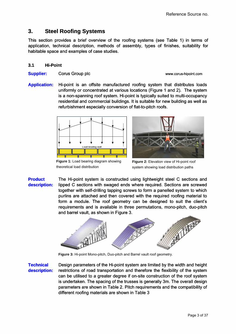
Supplier: Supplier: Corus Group plc www.corus-hipoint.comwww.corus-hipoint.com Corus Group plc Hi-point is an offsite manufactured roofing system that distributes loads uniformly or concentrated at various locations (Figure 1 and 2). The system is a non-spanning roof system. Hi-point is typically suited to multi-occupancy residential and commercial buildings. It is suitable for new building as well as refurbishment especially conversion of flat-to-pitch roofs.
Hi-point is an offsite manufactured roofing system that distributes loads uniformly or concentrated at various locations (Figure 1 and 2). The system is a non-spanning roof system. Hi-point is typically suited to multi-occupancy residential and commercial buildings. It is suitable for new building as well as refurbishment especially conversion of flat-to-pitch roofs.
Application: Application:
Product description: Product description:
The Hi-point system is constructed using lightweight steel C sections and lipped C sections with swaged ends where required. Sections are screwed together with self-drilling tapping screws to form a panelled system to which purlins are attached and then covered with the required roofing material to form a module. The roof geometry can be designed to suit the client’s requirements and is available in three permutations, mono-pitch, duo-pitch and barrel vault, as shown in Figure 3.
The Hi-point system is constructed using lightweight steel C sections and lipped C sections with swaged ends where required. Sections are screwed together with self-drilling tapping screws to form a panelled system to which purlins are attached and then covered with the required roofing material to form a module. The roof geometry can be designed to suit the client’s requirements and is available in three permutations, mono-pitch, duo-pitch and barrel vault, as shown in Figure 3.
Technical description: Technical description:
Design parameters of the Hi-point system are limited by the width and height restrictions of road transportation and therefore the flexibility of the system can be utilised to a greater degree if on-site construction of the roof system is undertaken. The spacing of the trusses is generally 3m. The overall design parameters are shown in Table 2. Pitch requirements and the compatibility of different roofing materials are shown in Table 3
Design parameters of the Hi-point system are limited by the width and height restrictions of road transportation and therefore the flexibility of the system can be utilised to a greater degree if on-site construction of the roof system is undertaken. The spacing of the trusses is generally 3m. The overall design parameters are shown in Table 2. Pitch requirements and the compatibility of different roofing materials are shown in Table 3
Figure 3: Hi-point Mono-pitch, Duo-pitch and Barrel vault roof geometry.
Figure 1: Load bearing diagram showing
theoretical load distribution
Figure 2: Elevation view of Hi-point roof
system showing load distribution paths
Page 3 of 37

DRAFT DRAFT
Reference Source no.
Assembly: Assembly:
Hi-point is available as a factory built complete unit delivered to site, ready to be installed at roof level or assembled at ground level and craned into position with all the components required for the finished roof e.g. guttering and fascias. This is enabled by the relatively light weight system used to construct the roof and the provision of adequate lifting points. The ground level assembly of Hi-point reduces working at height and overcomes size restrictions imposed by transportation.
Hi-point is available as a factory built complete unit delivered to site, ready to be installed at roof level or assembled at ground level and craned into position with all the components required for the finished roof e.g. guttering and fascias. This is enabled by the relatively light weight system used to construct the roof and the provision of adequate lifting points. The ground level assembly of Hi-point reduces working at height and overcomes size restrictions imposed by transportation.
Finishes: Finishes:
Hi-point can be covered in a range of finishes including self supporting and fully supported standing seam, composite panels, trapezoidal profiles, metal roof tiles or can be prepared to receive traditional roof tiles.
Hi-point can be covered in a range of finishes including self supporting and fully supported standing seam, composite panels, trapezoidal profiles, metal roof tiles or can be prepared to receive traditional roof tiles.
Suitability: Suitability:
The system is mainly designed for new build and refurbishment i.e. over roofing. The suitability of the Hi-point system to provide a habitable space within the roof void is possible but limited because of the spacing of the truss. For a habitable space to be created it is likely that the system would require some alterations to provide extra rigidity. The space available for habitation would be limited as the roof panels and framework would form a restricted floor area. In theory if the design of the system was optimised to reduce the number of load bearing panels, it could offer the possibility to provide 4m wide by up to 6m structural member free area on plan. This would require structural sections to be made from thicker gauge galvanised steel, furthermore height considerations would need to be made at the design stage to fully utilise the internal space.
The system is mainly designed for new build and refurbishment i.e. over roofing. The suitability of the Hi-point system to provide a habitable space within the roof void is possible but limited because of the spacing of the truss. For a habitable space to be created it is likely that the system would require some alterations to provide extra rigidity. The space available for habitation would be limited as the roof panels and framework would form a restricted floor area. In theory if the design of the system was optimised to reduce the number of load bearing panels, it could offer the possibility to provide 4m wide by up to 6m structural member free area on plan. This would require structural sections to be made from thicker gauge galvanised steel, furthermore height considerations would need to be made at the design stage to fully utilise the internal space.
Case Studies: Case Studies:
Hi-Point by Corus has already been successfully implemented in a number of refurbishments and new build projects: Hi-Point by Corus has already been successfully implemented in a number of refurbishments and new build projects:
The new Unity development of 27 storeys luxury apartments in Liverpool equipped with a striking 1.5 degree pitched Hi-Point gull wing roof, which sits 94 metres above the ground. The full 22 Hi-Point modules were lifted and bolted into position in just two days
The new Unity development of 27 storeys luxury apartments in Liverpool equipped with a striking 1.5 degree pitched Hi-Point gull wing roof, which sits 94 metres above the ground. The full 22 Hi-Point modules were lifted and bolted into position in just two days
As part of the MOD ten years improvement project “Project SLAM” (Single Living Accommodation Modernisation)
As part of the MOD ten years improvement project “Project SLAM” (Single Living Accommodation Modernisation)
Table 2: Design parameters Table 2: Pitch requirements and roof coverings
Page 4 of 37
DRAFT DRAFT
Reference Source no.
3.2 Gus Truss / Nu Truss 3.2 Gus Truss / Nu Truss
Supplier: Supplier: Nucon Steel www.nuconsteel.com, Nucon Steel www.nuconsteel.com,
Gus Truss Ltd www.gustrussfl.com Gus Truss Ltd www.gustrussfl.com
Application: Application:
This system is based on a conventional truss design but has the advantage of a unique splice system. Figure 4 shows a typical installation of the roof truss system. The system finds its application in low and medium rise multi-occupancy residential and various commercial buildings.
This system is based on a conventional truss design but has the advantage of a unique splice system. Figure 4 shows a typical installation of the roof truss system. The system finds its application in low and medium rise multi-occupancy residential and various commercial buildings.
Product description: Product description:
The system is a steel manifestation of traditional timber truss systems, and requires working at height as the truss is built at ground level and craned to roof level with additional work at height to install the roof finishes. Therefore the remaining battening and fixing of the roofing material is conducted in-situ (Figure 7).
The system is a steel manifestation of traditional timber truss systems, and requires working at height as the truss is built at ground level and craned to roof level with additional work at height to install the roof finishes. Therefore the remaining battening and fixing of the roofing material is conducted in-situ (Figure 7).
Technical description: Technical description:
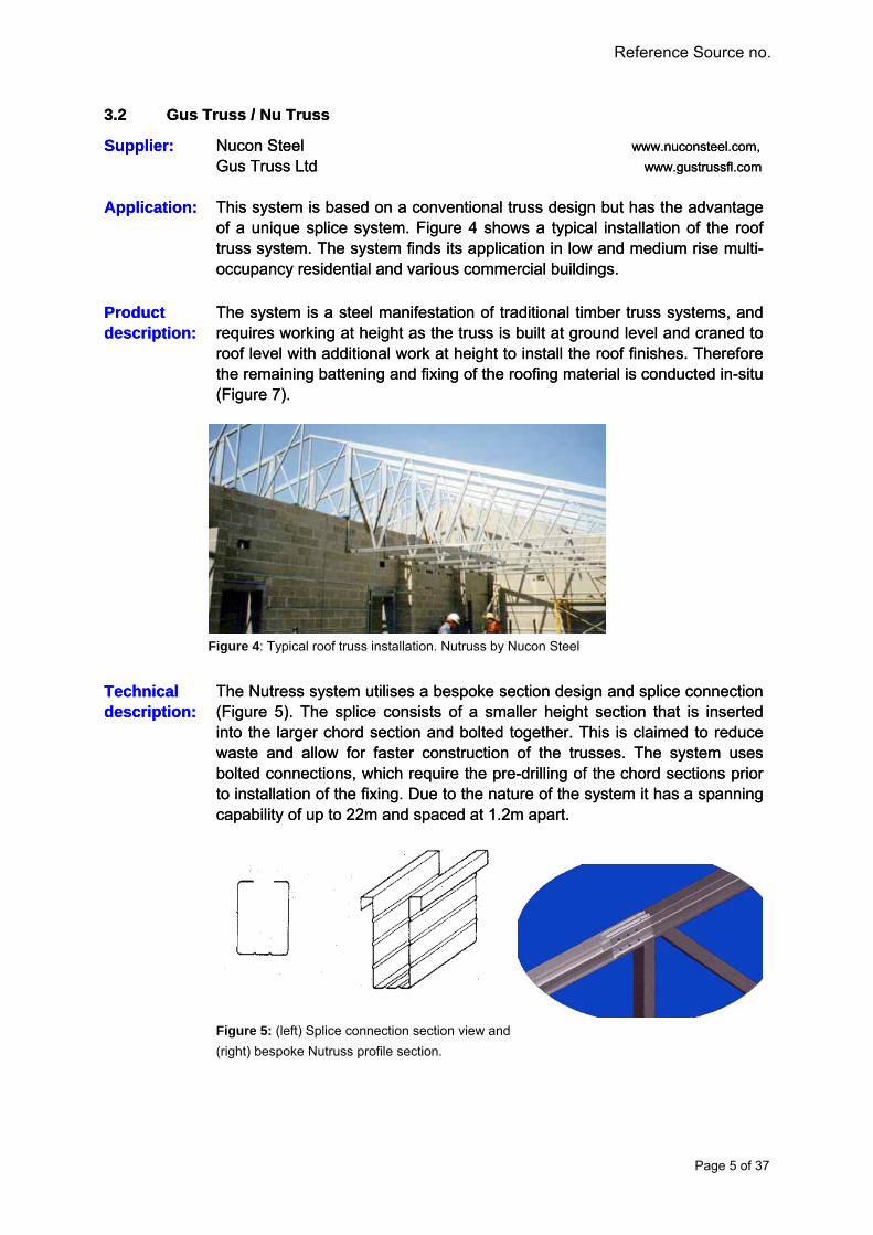
The Nutress system utilises a bespoke section design and splice connection (Figure 5). The splice consists of a smaller height section that is inserted into the larger chord section and bolted together. This is claimed to reduce waste and allow for faster construction of the trusses. The system uses bolted connections, which require the pre-drilling of the chord sections prior to installation of the fixing. Due to the nature of the system it has a spanning capability of up to 22m and spaced at 1.2m apart.
The Nutress system utilises a bespoke section design and splice connection (Figure 5). The splice consists of a smaller height section that is inserted into the larger chord section and bolted together. This is claimed to reduce waste and allow for faster construction of the trusses. The system uses bolted connections, which require the pre-drilling of the chord sections prior to installation of the fixing. Due to the nature of the system it has a spanning capability of up to 22m and spaced at 1.2m apart.
Figure 5: (left) Splice connection section view and
(right) bespoke Nutruss profile section.
Figure 4: Typical roof truss installation. Nutruss by Nucon Steel
Page 5 of 37

DRAFT DRAFT
Reference Source no.
Assembly: Assembly:
The system is formed, cut and assembled into trusses on site at ground level and craned to roof level with additional work at height to install the roof finishes. The production of the system on site is facilitated by portable equipment capable of forming, cutting and machining the profiles from coils of galvanised light gauge steel. This is a novel approach which enables precise manufacturing of the trusses adjacent or nearby the installation point (Figure 6).
The system is formed, cut and assembled into trusses on site at ground level and craned to roof level with additional work at height to install the roof finishes. The production of the system on site is facilitated by portable equipment capable of forming, cutting and machining the profiles from coils of galvanised light gauge steel. This is a novel approach which enables precise manufacturing of the trusses adjacent or nearby the installation point (Figure 6).
Finishes: Finishes:
A range of finishes including self supporting and fully supported standing seam, composite panels, trapezoidal profiles, metal roof tiles and traditional roof tiles are possible.
A range of finishes including self supporting and fully supported standing seam, composite panels, trapezoidal profiles, metal roof tiles and traditional roof tiles are possible.
Suitability: Suitability:
The system is mainly designed for new build and refurbishment i.e. over roofing. It requires structural alteration for creating room in the roof as the truss design and truss spacing limit the available space and the available headroom.
The system is mainly designed for new build and refurbishment i.e. over roofing. It requires structural alteration for creating room in the roof as the truss design and truss spacing limit the available space and the available headroom.
Case Studies: Case Studies:
An example of the Nutruss system on large a residential development. The high pitch of the roof can be seen and the entire roof structure awaits installation of the roof covering.
An example of the Nutruss system on large a residential development. The high pitch of the roof can be seen and the entire roof structure awaits installation of the roof covering.
Figure 6: On site truss manufacturing system. Nucon steel.
Figure 7: Truss system installed and awaiting roof covering
Page 6 of 37
DRAFT DRAFT
Reference Source no.
3.3 Dibsa 3.3 Dibsa
Supplier: Supplier: Dibsa Structures Limited www.dibsa.co.ukwww.dibsa.co.uk Dibsa Structures Limited Dibsa is an over-roofing or flat-to-pitch conversion (Figure 8) solution. It is suitable for use on new buildings or as part of renovation works. The system is designed, supplied and manufactured in-house and caters for the residential and commercial markets.
Dibsa is an over-roofing or flat-to-pitch conversion (Figure 8) solution. It is suitable for use on new buildings or as part of renovation works. The system is designed, supplied and manufactured in-house and caters for the residential and commercial markets.
Application: Application:
Product description: Product description:
The system is constructed using lightweight steel “L” and “top hat” sections bolted in a truss configuration. Trusses are capable of spans of up to 12m and are also available in a non-spanning continually supported format. Typical truss spacing is in the range of 300mm to 900mm depending on the type of roof covering.
The system is constructed using lightweight steel “L” and “top hat” sections bolted in a truss configuration. Trusses are capable of spans of up to 12m and are also available in a non-spanning continually supported format. Typical truss spacing is in the range of 300mm to 900mm depending on the type of roof covering.
Technical description: Technical description:
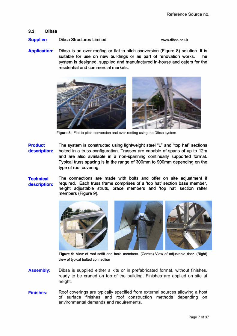
The connections are made with bolts and offer on site adjustment if required. Each truss frame comprises of a 'top hat' section base member, height adjustable struts, brace members and 'top hat' section rafter members (Figure 9).
The connections are made with bolts and offer on site adjustment if required. Each truss frame comprises of a 'top hat' section base member, height adjustable struts, brace members and 'top hat' section rafter members (Figure 9).
Figure 9: View of roof soffit and facia members. (Centre) View of adjustable riser. (Right)
view of typical bolted connection
Figure 9: View of roof soffit and facia members. (Centre) View of adjustable riser. (Right)
view of typical bolted connection
Assembly:
Dibsa is supplied either a kits or in prefabricated format, without finishes, ready to be craned on top of the building. Finishes are applied on site at height.
Finishes:
Roof coverings are typically specified from external sources allowing a host of surface finishes and roof construction methods depending on environmental demands and requirements.
Figure 8: Flat-to-pitch conversion and over-roofing using the Dibsa system
Page 7 of 37

DRAFT DRAFT
Reference Source no.
Suitability: Suitability:
The system is mainly designed for new build and refurbishment i.e. over roofing. It requires structural alteration for creating room in the roof as the truss design and truss spacing limit the available space and the available headroom.
The system is mainly designed for new build and refurbishment i.e. over roofing. It requires structural alteration for creating room in the roof as the truss design and truss spacing limit the available space and the available headroom.
Case Studies: Case Studies:
Installation of the Dibsa truss system to upgrade from flat to pitch roof in Leeds UK. Figure 10 shows the existing roof prior to upgrade. Viewed along the ridge line Figure 11 indicates the typical truss spacing and Figure 12 shows the Dibsa truss system partially covered with roof tiles.
Installation of the Dibsa truss system to upgrade from flat to pitch roof in Leeds UK. Figure 10 shows the existing roof prior to upgrade. Viewed along the ridge line Figure 11 indicates the typical truss spacing and Figure 12 shows the Dibsa truss system partially covered with roof tiles.
Figure 10: Existing flat roof prior to refurbishment Figure 10: Existing flat roof prior to refurbishment
Figure 11: View along rigle line, indicative of typical truss spacing Figure 11: View along rigle line, indicative of typical truss spacing
Figure 12: Partially completed roof with tile roof covering
Page 8 of 37
DRAFT DRAFT
Reference Source no.
3.4 Capella Pin Truss 3.4 Capella Pin Truss
Supplier: Supplier: Kingspan www.kingspanmetlcon.com Kingspan www.kingspanmetlcon.com
Application: Application:
This truss system is suitable for small to medium sized commercial flat-to-pitch roof conversions as well as new roof structures. The system is offered as a complete service including initial survey, structural design, support system options, roof panel options, flashings and the provision of rainwater goods through to installation on site by Kingspan approved contractors.
This truss system is suitable for small to medium sized commercial flat-to-pitch roof conversions as well as new roof structures. The system is offered as a complete service including initial survey, structural design, support system options, roof panel options, flashings and the provision of rainwater goods through to installation on site by Kingspan approved contractors.
Product description: Product description:
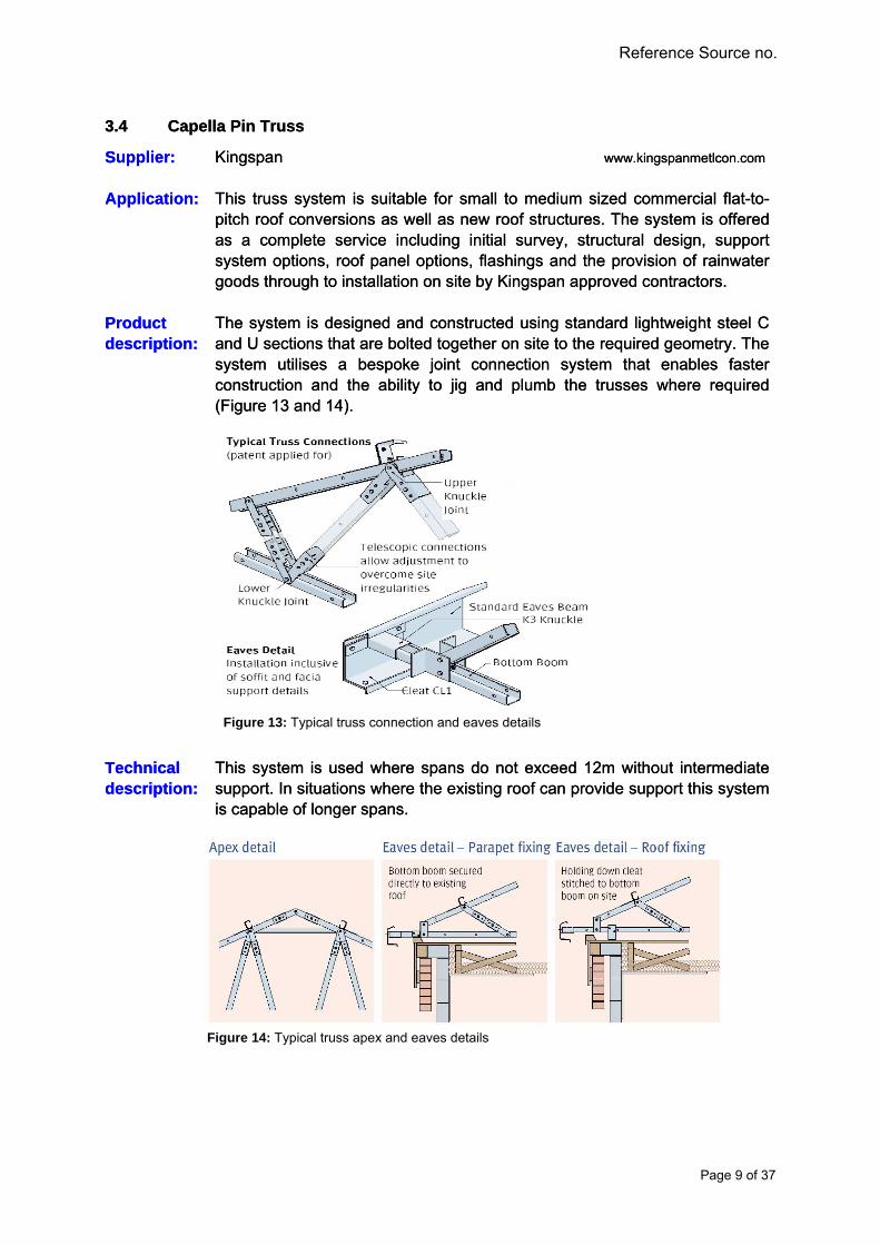
The system is designed and constructed using standard lightweight steel C and U sections that are bolted together on site to the required geometry. The system utilises a bespoke joint connection system that enables faster construction and the ability to jig and plumb the trusses where required (Figure 13 and 14).
The system is designed and constructed using standard lightweight steel C and U sections that are bolted together on site to the required geometry. The system utilises a bespoke joint connection system that enables faster construction and the ability to jig and plumb the trusses where required (Figure 13 and 14).
Technical description: Technical description:
This system is used where spans do not exceed 12m without intermediate support. In situations where the existing roof can provide support this system is capable of longer spans.
This system is used where spans do not exceed 12m without intermediate support. In situations where the existing roof can provide support this system is capable of longer spans.
Figure 13: Typical truss connection and eaves details
Figure 14: Typical truss apex and eaves details
Page 9 of 37

DRAFT DRAFT
Reference Source no.
Assembly:
The truss system is generally supplied as a kit of parts to contractors who specialise in roof installations and refurbishment. Truss can be constructed at ground level and fixed at roof level or alternatively all the work can be carried out at roof level. Finishes are applied at height once trusses have been installed.
Finishes:
Roof coverings are from within the Kingspan’s range and generally assumed to be either metal tile effect or metal profile sheets. Although traditional roof tiles could be used if required.
Suitability:
The system is mainly designed for new build and refurbishment i.e. over roofing. It requires structural alteration for creating room in the roof as the truss design and truss spacing limit the available space and the available headroom.
Case Studies:
Refurbishment of flat roofs to pitched roofs for 15 bungalows (Figure 15), two high rise blocks (Figure 16) and a warden house on the housing estate in Leeds UK.
Figure 15: Renovation of 15 flat roofs to piched roofs using the Capella system
Figure 16: Renovation of high rise roofs using the Capella system
Page 10 of 37

DRAFT DRAFT
Reference Source no.
3.5 Capella Vierendeel Truss System 3.5 Capella Vierendeel Truss System
Supplier: Supplier: Kingspan www.kingspanmetlcon.com Kingspan www.kingspanmetlcon.com
Application: Application:
This truss system is suitable for small to medium sized commercial flat-to-pitch roof conversions as well as new roof structures. The system is offered as a complete service including initial survey, structural design, support system options, roof panel options, flashings and the provision of rainwater goods through to installation on site by Kingspan approved contractors.
This truss system is suitable for small to medium sized commercial flat-to-pitch roof conversions as well as new roof structures. The system is offered as a complete service including initial survey, structural design, support system options, roof panel options, flashings and the provision of rainwater goods through to installation on site by Kingspan approved contractors.
Product description: Product description:
The design of the truss is similar to that of a conventional Vierendeel truss as shown in Figure 19. The design of the truss is similar to that of a conventional Vierendeel truss as shown in Figure 19.
Technical description: Technical description:
This system is capable of spans of up to 30m. It is constructed using MultiChannel C-shaped sections and MultiBeam Z-shaped sections (Figure 17 and 18). These sections are connected using bolted connection similar in manner to the Capella Pin System. Truss spacing ranges from 300mm upwards depending on loading.
This system is capable of spans of up to 30m. It is constructed using MultiChannel C-shaped sections and MultiBeam Z-shaped sections (Figure 17 and 18). These sections are connected using bolted connection similar in manner to the Capella Pin System. Truss spacing ranges from 300mm upwards depending on loading.
Assembly: Assembly:
The truss system is generally supplied as a kit of parts to contractors who specialise in roof installations and refurbishment. Truss can be constructed at ground level and fixed at roof level or alternatively all the work can be carried out at roof level.
The truss system is generally supplied as a kit of parts to contractors who specialise in roof installations and refurbishment. Truss can be constructed at ground level and fixed at roof level or alternatively all the work can be carried out at roof level.
Finishes: Finishes:
Roof coverings are from within the Kingspan range and generally assumed to be either metal tile effect or metal profile sheets. Although, traditional roof coverings are possible.
Roof coverings are from within the Kingspan range and generally assumed to be either metal tile effect or metal profile sheets. Although, traditional roof coverings are possible.
Suitability: Suitability:
The system is mainly designed for new build and refurbishment i.e. over roofing. It requires structural alteration for creating room in the roof as the truss design and truss spacing limit the available space and the available headroom.
The system is mainly designed for new build and refurbishment i.e. over roofing. It requires structural alteration for creating room in the roof as the truss design and truss spacing limit the available space and the available headroom.
Case Studies: Case Studies:
As above As above
Figure 19: Truss layout and geometry
Figure 17: MultiChannel C-sections
Figure 18: MultiBeam Z-sections
Page 11 of 37

DRAFT DRAFT
Reference Source no.
3.6 AyrTruss
Supplier: Ayrshire Steel Framing www.ayrshire.co.uk
The Ayrshire truss system is a prefabricated off-site manufactured truss system that is suitable for over-roofing and new construction (Figure 20 and 21).
Application:
Figure 20: Ayrtruss awaiting traditional tile roof covering
Product description:
The system is somewhat traditional in its approach and does not utilise advances in lightweight metal technology and joining technology. Truss geometry is similar in nature to that of timber, however due to the connection system and the thickness of the steel sections; large support free spans are possible.
Technical description:
Truss depth ranges from 0.4m to 1.2m depending on application and span. The connections are formed using welded connections.
Assembly:
The system is assembled off-site in a factory controlled environment, transported to site, installed at roof level and roof coverings are installed in-situ.
Finishes: A wide range of finishes are possible
Suitability: The system is mainly designed for new build and refurbishment i.e. over roofing. It requires structural alteration for creating room in the roof as the truss design and truss spacing limit the available space and the available headroom.
Case Studies:
Figure 21: Ayrtruss used in conjunction with a complete framing solution also supplied by
Ayrshire
Page 12 of 37

DRAFT DRAFT
Reference Source no.
3.7 Ashjack
Figure 22: Examples of propped rafter (left) and
curved rafter (right) over-roof conversion system
Figure 23: Example of spanning truss over-roof
conversion system
Supplier: Ash and Lacy Building Systems www.ashandlacy.com
Application:
AshJack is suitable for use as an off-site new build solution or as part of a renovation package (Figure 25) to overcome flat roof failure
Product description:
The system is a constructed using lightweight steel section. It is possible to have a continuously supported rafter design (Figure 22) or a spanning truss system as shown in Figure 23.
Technical description:
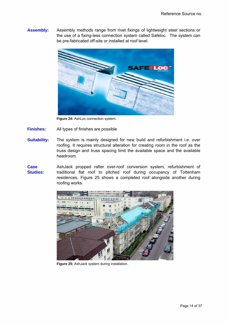
The system is able to span up to 15m with a maximum pitch of 35° and is available in traditional pitch or barrel vault (Figure 22) configuration. Connections are by made by mechanical screw fixing or bolt connections and splice connections are possible with the AshLoc (Figure 24) system if required. Spacing is dependent on imposed and dead loads assumed to be in the region of 300mm to 1200mm
Page 13 of 37
DRAFT DRAFT
Reference Source no.
Assembly:
Assembly methods range from rivet fixings of lightweight steel sections or the use of a fixing-less connection system called Safeloc. The system can be pre-fabricated off-site or installed at roof level.
Figure 24: AshLoc connection system.
Finishes: All types of finishes are possible
Suitability:
The system is mainly designed for new build and refurbishment i.e. over roofing. It requires structural alteration for creating room in the roof as the truss design and truss spacing limit the available space and the available headroom.
Case Studies:
AshJack propped rafter over-roof conversion system, refurbishment of traditional flat roof to pitched roof during occupancy of Tottenham residences. Figure 25 shows a completed roof alongside another during roofing works.
Figure 25: AshJack system during installation.
Page 14 of 37

DRAFT DRAFT
Reference Source no.
3.8 Fusion Building Solutions 3.8 Fusion Building Solutions
Fusion Building Solutions www.fusionbuildingsystem.com Fusion Building Solutions www.fusionbuildingsystem.com Supplier: Supplier:
Application: Application:
The roof truss system is part of a total building solution for residential market. The roof truss system is part of a total building solution for residential market.
Product description: Product description:
This roofing system is based on the warm frame principle. It has proprietary shaped web and chord members. Some connection details are also unique and have patent protection.
This roofing system is based on the warm frame principle. It has proprietary shaped web and chord members. Some connection details are also unique and have patent protection.
Technical description: Technical description:
The system is reliant on bolted connections and has a proprietary connection system where truss members intersect; it is predominantly based on the clinched ends of the sections overlaying each other (Figure 26). Span capacity is not available. However it is assumed that the truss system is capable circa 15m spans.
The system is reliant on bolted connections and has a proprietary connection system where truss members intersect; it is predominantly based on the clinched ends of the sections overlaying each other (Figure 26). Span capacity is not available. However it is assumed that the truss system is capable circa 15m spans.
Assembly: Assembly:
The trusses are manufactured offsite, delivered to site pre-assembled and lifted to roof level for installation (Figure 27). The trusses are manufactured offsite, delivered to site pre-assembled and lifted to roof level for installation (Figure 27).
Finishes: Finishes: A variety of finishes are possible A variety of finishes are possible
Suitability: Suitability:
The truss system is not suitable for room-in-roof due to limitation of spacing and headroom. However, of particular interest is the fusion STiF (assumed to be an acronym for ‘STeel Insulated Frame) panel (Figure 28 and 29), which is steel equivalent of the timber based structurally insulated panel (SIP). This system should be capable of providing a room-in-roof solution. Also, it may be possible to adapt this system to suit the requirements of over-roofing and renovation.
The truss system is not suitable for room-in-roof due to limitation of spacing and headroom. However, of particular interest is the fusion STiF (assumed to be an acronym for ‘STeel Insulated Frame) panel (Figure 28 and 29), which is steel equivalent of the timber based structurally insulated panel (SIP). This system should be capable of providing a room-in-roof solution. Also, it may be possible to adapt this system to suit the requirements of over-roofing and renovation.
Figure 26: Fusion clinched connection system Figure 27: Fusion truss erection/installation
Figure 28: Fusion STiF wall panels Figure 29: Fusion STiF wall panels
Page 15 of 37

DRAFT DRAFT
Reference Source no.
Case Studies:
This development is an example of mixed residential contemporary three storeys, two bedroom apartments (Figure 30). Fusion has installed their revolutionary StIFTM Infill Panel in this development. Construction: Fusion StIFTM external non-load bearing Infill Panel was used within a Hot Rolled Steel Framed structure (Figure 31). The infill panels are designed to resist their self weight and imposed wind loading, due to the action of masonry cladding which is tied to the studs using the Fusion wall tie system.
Figure 30: Fusion building, mixed residential contemporary three storey, two bedroom
apartments
Figure 31: Fusion StIFTM external non-load bearing Infill Panel
Page 16 of 37

DRAFT DRAFT
Reference Source no.
3.9 Rosette 3.9 Rosette
Rosette Systems Ltd www.resettesystems.com Rosette Systems Ltd www.resettesystems.com Supplier: Supplier:
Application: Application:
The rosette system is a complete system capable of manufacturing all the components required for a lightweight steel framed structure. The rosette system is a complete system capable of manufacturing all the components required for a lightweight steel framed structure.
Product description: Product description:
The Rosette system is supplied as a system; comprising the steel forming machine, punches and presses for forming the connections and C and U sections. In addition the system is capable of forming and machining the “Bigboy” section (Figure 32) and truss system.
The Rosette system is supplied as a system; comprising the steel forming machine, punches and presses for forming the connections and C and U sections. In addition the system is capable of forming and machining the “Bigboy” section (Figure 32) and truss system.
Technical description: Technical description:
The Bigboy truss can span up to 20m with the truss spaced at 2.7m apart. The novelty of system lies with the development of a screw/boltless fixing method using the “Rosette Bolt Tube” as shown in Figure 33. The bolt tube system is aimed at reducing time needed to change tools and is also a patented product. The Rosette connection is formed using a prefabricated collar and distorting the sheet material to create a mechanical fixing with the lap as seen in Figure 34, which also shows the Rosette pressing tools etc.
The Bigboy truss can span up to 20m with the truss spaced at 2.7m apart. The novelty of system lies with the development of a screw/boltless fixing method using the “Rosette Bolt Tube” as shown in Figure 33. The bolt tube system is aimed at reducing time needed to change tools and is also a patented product. The Rosette connection is formed using a prefabricated collar and distorting the sheet material to create a mechanical fixing with the lap as seen in Figure 34, which also shows the Rosette pressing tools etc.
Figure 33: Rosette Bolt tube.
Figure 32: Rosette “Bigboy” section
Figure 34: (left) Rosette connection, (right) Rosette connection forming press
Figure 35: Connection of perpendicular
members, insertion of first Bolt Tube
Figure 36: Connection of perpendicular
members, insertion of second Bolt Tube
Page 17 of 37

DRAFT DRAFT
Reference Source no.
Assembly: Assembly:
Production of lightweight steel components is generally conducted off-site in production facilities and transported to site as either, components (channels etc) or building elements (trusses, panels etc). Installation on-site is dependent on the manufacturer and the supply format. Components require on site assembly, building elements are simply installed as units.
Production of lightweight steel components is generally conducted off-site in production facilities and transported to site as either, components (channels etc) or building elements (trusses, panels etc). Installation on-site is dependent on the manufacturer and the supply format. Components require on site assembly, building elements are simply installed as units.
Finishes: Finishes:
A variety of finishes are possible A variety of finishes are possible
Suitability: Suitability:
It appears that the system is mainly designed for new build. The ability to provide a room-in-roof solution is unclear. However, akin to the other truss solutions discussed in this report the truss spacing and layout is possibly a restricting factor.
It appears that the system is mainly designed for new build. The ability to provide a room-in-roof solution is unclear. However, akin to the other truss solutions discussed in this report the truss spacing and layout is possibly a restricting factor.
Case Studies: Case Studies:
Schematic of the complete buildign system capable of being produced by the rosette system.
Schematic of the complete buildign system capable of being produced by the rosette system.
Figure 37: Connection with slotted
bracket to aid adjustment
Figure 38: Connection of perpendicular
members with multiple bolt tubes
Figure 39: Rosette truss configuration with
tie member
Figure 40: Bigboy section and truss with
Tube Bolt locations
Figure 41: Components manufactured with the Rosette System
Page 18 of 37

DRAFT DRAFT
Reference Source no.
3.10 Metsec Trusses 3.10 Metsec Trusses
Supplier: Supplier: Metsec Plc www.metsec.co.uk Metsec Plc www.metsec.co.uk Metsec has traditionally supplied off-site manufactured parallel chord trusses that utilise a unique chord section, as shown in Figure 42. Metsec specialises in cold roll-forming of metal sections. It has a host of truss solutions for new built residential, commercial and industrial application and has recently extended its remit to over-roofing.
Metsec has traditionally supplied off-site manufactured parallel chord trusses that utilise a unique chord section, as shown in Figure 42. Metsec specialises in cold roll-forming of metal sections. It has a host of truss solutions for new built residential, commercial and industrial application and has recently extended its remit to over-roofing.
Application: Application:
Product description: Product description:
Metsec currently offers pitched trusses (Figure 43 and 44), tapered, tapered inverted trusses, curved beams (Figure 45) and curved trusses (Figure 46). These are used to create over-roofing solutions and designed to suit individual requirements.
Metsec currently offers pitched trusses (Figure 43 and 44), tapered, tapered inverted trusses, curved beams (Figure 45) and curved trusses (Figure 46). These are used to create over-roofing solutions and designed to suit individual requirements.
Technical description: Technical description:
Metsec trusses are typically welded and are capable of long spans of up to 34m. Metsec trusses are typically welded and are capable of long spans of up to 34m.
Assembly: Assembly:
Metsec trusses are manufactured off site. In over-roofing scenarios, the trusses receive roof coverings on site and at height. Metsec trusses are manufactured off site. In over-roofing scenarios, the trusses receive roof coverings on site and at height.
Finishes: Finishes:
Roof finishes are generally profiled sheet materials but traditional roofing tiles are possible. Roof finishes are generally profiled sheet materials but traditional roofing tiles are possible.
Suitability: Suitability:
The system is mainly designed for new build and refurbishment i.e. over roofing. Like many other truss systems, the feasibility of a room-in-roof solution is restricted by the truss layout and geometry. Curved beams could be used to create a habitable space; however careful consideration must be given to the existing structure as it likely that the curved beams will exhort lateral forces upon it. If the underlying structure is able to resist the lateral and vertical loads imposed by the curved beams a habitable space is achievable using the Metsec system.
The system is mainly designed for new build and refurbishment i.e. over roofing. Like many other truss systems, the feasibility of a room-in-roof solution is restricted by the truss layout and geometry. Curved beams could be used to create a habitable space; however careful consideration must be given to the existing structure as it likely that the curved beams will exhort lateral forces upon it. If the underlying structure is able to resist the lateral and vertical loads imposed by the curved beams a habitable space is achievable using the Metsec system.
Figure 42: Unique chord profile Figure 43: Metsec parallel chord trusses
used in roof construction
Figure 44: Metsec pitched trusses used
in a new build project
Figure 45: Metsec curved beam shown above
during new construction, could also be used
during renovation.
Page 19 of 37

DRAFT DRAFT
Reference Source no.
Case Studies: Case Studies:
Figure 46: Metsec curved truss shown above
during new construction, however the curved
truss is ideally suited to renovation as it could be
continuously supported by existing roof.
Figure 47: Over-roofing of school using
traditional truss system
Page 20 of 37

DRAFT DRAFT
Reference Source no.
3.11 Cover Structure 3.11 Cover Structure
Cover Structure www.coverstructure.com Cover Structure www.coverstructure.com Supplier: Supplier:
Application: Application:
Cover Structure manufacture and install over-roofing and flat-to-pitch solutions to the residential and commercial sectors in the UK. The mainstay of their business activity is the over-roofing of dilapidated and aging flat roofs in schools, leisure centres and homes. The Cover Structure system is promoted as the solution to budget-sapping patch repairs.
Cover Structure manufacture and install over-roofing and flat-to-pitch solutions to the residential and commercial sectors in the UK. The mainstay of their business activity is the over-roofing of dilapidated and aging flat roofs in schools, leisure centres and homes. The Cover Structure system is promoted as the solution to budget-sapping patch repairs.
Product description: Product description:
The system is traditional in its construction without many differentiators to other systems discussed in this report. It uses standard C-sections in its construction which are connected using blind rivets and connection plates as shown in Figure 48 and 49.
The system is traditional in its construction without many differentiators to other systems discussed in this report. It uses standard C-sections in its construction which are connected using blind rivets and connection plates as shown in Figure 48 and 49.
Technical description: Technical description:
The system is a truss based system capable of spans of up to 25m in simply supported scenarios and longer if intermediate supports are available (Figure 50). Typical truss spacing is between 1m and 1.2m.
The system is a truss based system capable of spans of up to 25m in simply supported scenarios and longer if intermediate supports are available (Figure 50). Typical truss spacing is between 1m and 1.2m.
Assembly: Assembly:
Trusses are manufactured off site and the trusses receive roof coverings on site and at height. Trusses are manufactured off site and the trusses receive roof coverings on site and at height.
Finishes: Finishes: A variety of roof finishes are possible. A variety of roof finishes are possible.
Suitability: Suitability: The system is mainly designed for new build and refurbishment i.e. over roofing. It requires structural alteration for creating room in the roof, similar to other truss systems.
The system is mainly designed for new build and refurbishment i.e. over roofing. It requires structural alteration for creating room in the roof, similar to other truss systems.
Figure 49: Plate connection system used in
construction on the Cover Structure truss.
Figure 48: Blind rivet construction of
Cover Structure truss.
Figure 50: Typical truss detail
Page 21 of 37

DRAFT DRAFT
Reference Source no.
Case Studies: Case Studies:
Before and after images showing the scope of works carried out by Cover Structure are shown in Figure 51 and 52. Before and after images showing the scope of works carried out by Cover Structure are shown in Figure 51 and 52.
Figure 51: Flat-to-pitch conversion of production building
Figure 52: Flat-to-pitch conversion of production building
Page 22 of 37
DRAFT DRAFT
Reference Source no.
4. Other Products / Systems of Interest 4. Other Products / Systems of Interest
4.1 Freeframe 4.1 Freeframe
The Freeframe system is similar to conventional light weight steel framing solutions in that it utilises C- and U-sections for its manufacture. The system can be used to produce lightweight steel framing and truss.
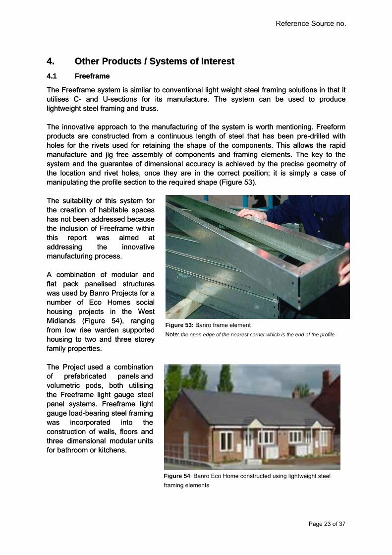
The Freeframe system is similar to conventional light weight steel framing solutions in that it utilises C- and U-sections for its manufacture. The system can be used to produce lightweight steel framing and truss. The innovative approach to the manufacturing of the system is worth mentioning. Freeform products are constructed from a continuous length of steel that has been pre-drilled with holes for the rivets used for retaining the shape of the components. This allows the rapid manufacture and jig free assembly of components and framing elements. The key to the system and the guarantee of dimensional accuracy is achieved by the precise geometry of the location and rivet holes, once they are in the correct position; it is simply a case of manipulating the profile section to the required shape (Figure 53).
The innovative approach to the manufacturing of the system is worth mentioning. Freeform products are constructed from a continuous length of steel that has been pre-drilled with holes for the rivets used for retaining the shape of the components. This allows the rapid manufacture and jig free assembly of components and framing elements. The key to the system and the guarantee of dimensional accuracy is achieved by the precise geometry of the location and rivet holes, once they are in the correct position; it is simply a case of manipulating the profile section to the required shape (Figure 53). The suitability of this system for the creation of habitable spaces has not been addressed because the inclusion of Freeframe within this report was aimed at addressing the innovative manufacturing process.
The suitability of this system for the creation of habitable spaces has not been addressed because the inclusion of Freeframe within this report was aimed at addressing the innovative manufacturing process. A combination of modular and flat pack panelised structures was used by Banro Projects for a number of Eco Homes social housing projects in the West Midlands (Figure 54), ranging from low rise warden supported housing to two and three storey family properties.
A combination of modular and flat pack panelised structures was used by Banro Projects for a number of Eco Homes social housing projects in the West Midlands (Figure 54), ranging from low rise warden supported housing to two and three storey family properties.
Figure 53: Banro frame element
Note: the open edge of the nearest corner which is the end of the profile
The Project used a combination of prefabricated panels and volumetric pods, both utilising the Freeframe light gauge steel panel systems. Freeframe light gauge load-bearing steel framing was incorporated into the construction of walls, floors and three dimensional modular units for bathroom or kitchens.
The Project used a combination of prefabricated panels and volumetric pods, both utilising the Freeframe light gauge steel panel systems. Freeframe light gauge load-bearing steel framing was incorporated into the construction of walls, floors and three dimensional modular units for bathroom or kitchens.
Figure 54: Banro Eco Home constructed using lightweight steel
framing elements
Page 23 of 37
DRAFT DRAFT
Reference Source no.
4.2 AyrFrame 4.2 AyrFrame
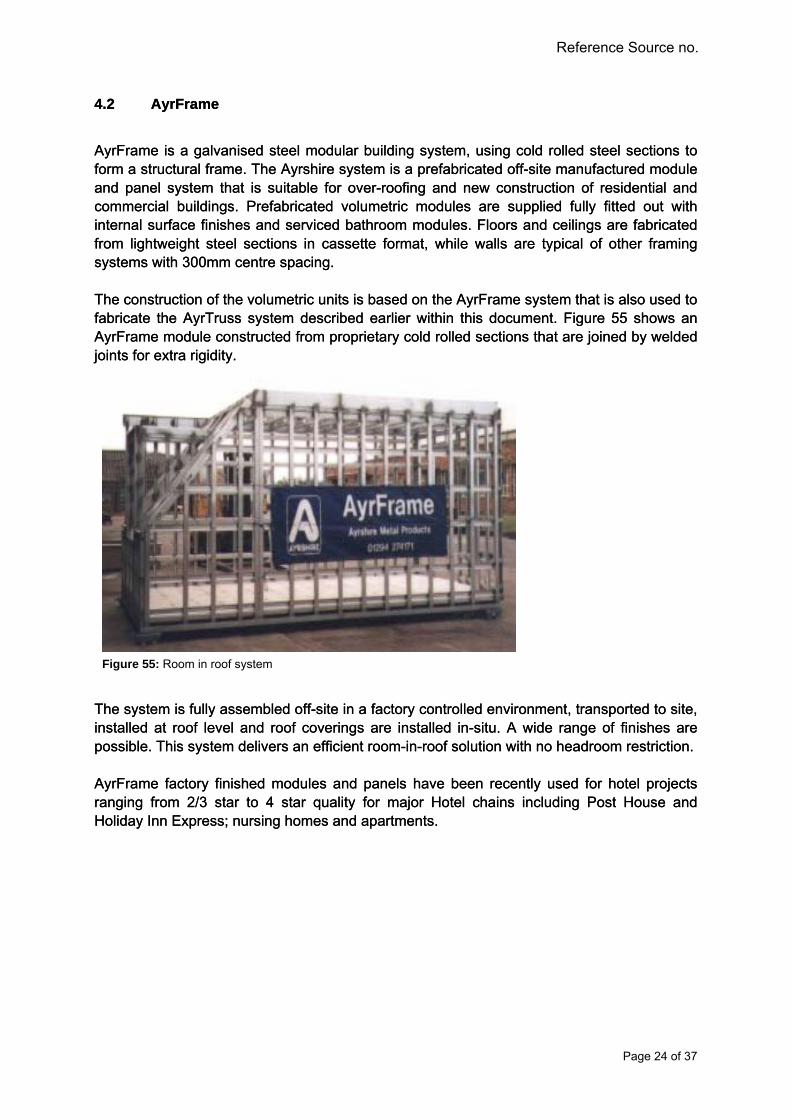
AyrFrame is a galvanised steel modular building system, using cold rolled steel sections to form a structural frame. The Ayrshire system is a prefabricated off-site manufactured module and panel system that is suitable for over-roofing and new construction of residential and commercial buildings. Prefabricated volumetric modules are supplied fully fitted out with internal surface finishes and serviced bathroom modules. Floors and ceilings are fabricated from lightweight steel sections in cassette format, while walls are typical of other framing systems with 300mm centre spacing.
AyrFrame is a galvanised steel modular building system, using cold rolled steel sections to form a structural frame. The Ayrshire system is a prefabricated off-site manufactured module and panel system that is suitable for over-roofing and new construction of residential and commercial buildings. Prefabricated volumetric modules are supplied fully fitted out with internal surface finishes and serviced bathroom modules. Floors and ceilings are fabricated from lightweight steel sections in cassette format, while walls are typical of other framing systems with 300mm centre spacing. The construction of the volumetric units is based on the AyrFrame system that is also used to fabricate the AyrTruss system described earlier within this document. Figure 55 shows an AyrFrame module constructed from proprietary cold rolled sections that are joined by welded joints for extra rigidity.
The construction of the volumetric units is based on the AyrFrame system that is also used to fabricate the AyrTruss system described earlier within this document. Figure 55 shows an AyrFrame module constructed from proprietary cold rolled sections that are joined by welded joints for extra rigidity.
Figure 55: Room in roof system The system is fully assembled off-site in a factory controlled environment, transported to site, installed at roof level and roof coverings are installed in-situ. A wide range of finishes are possible. This system delivers an efficient room-in-roof solution with no headroom restriction.
The system is fully assembled off-site in a factory controlled environment, transported to site, installed at roof level and roof coverings are installed in-situ. A wide range of finishes are possible. This system delivers an efficient room-in-roof solution with no headroom restriction. AyrFrame factory finished modules and panels have been recently used for hotel projects ranging from 2/3 star to 4 star quality for major Hotel chains including Post House and Holiday Inn Express; nursing homes and apartments.
AyrFrame factory finished modules and panels have been recently used for hotel projects ranging from 2/3 star to 4 star quality for major Hotel chains including Post House and Holiday Inn Express; nursing homes and apartments.
Page 24 of 37

DRAFT DRAFT
Reference Source no.
4.3 Moment Frame
The system is a lightweight cold rolled sections configured to provide portal frame structures of up to 18m in width. Current applications of this system are confined to small portal frames with maximum spans of up to 18m in width with a maximum length of 54m. The combination of SwageBeams and connections provides the opportunity to utilise the portal frame design to create room in roof solutions (Figure 56).
Figure 56: Details of the various framing options available, of particular interest is the over-roof system
Figure 57: Typical building widths and heights offered by the system
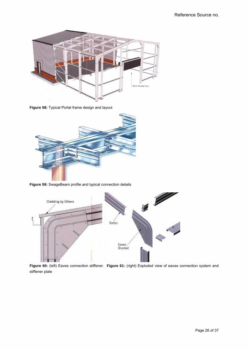
The system represents a lightweight alternative to hot-rolled steel sections which are traditionally used for single-storey structures providing large open spaces (Figure 58). The system is based on the Ayrshire SwageBeam, a proprietary cold-rolled lightweight steel section derived from a lipped “C” section that minimises section depth whilst maximising span capabilities due to added web stiffener (Figure 59). The moment resisting capabilities of the framing system are increased by special eaves and ridge connection systems (Figure 60 and 62 respectively).
Page 25 of 37
DRAFT DRAFT
Reference Source no.
Figure 58: Typical Portal frame design and layout
Figure 59: SwageBeam profile and typical connection details
Figure 60: (left) Eaves connection stiffener. Figure 61: (right) Exploded view of eaves connection system and
stiffener plate
Page 26 of 37

DRAFT DRAFT
Reference Source no.
Figure 62: Exploded view of moment resisting ridge connection
Assembly of the framing system is conducted on-site and in-situ. Connections are formed with bolts, cleats and stiffening plates. Framing elements can be painted for increased aesthetics or intumescent paint can be applied to increase fire resistance. External panel finishes can comprise of either built-up or composite panel systems with a variety of surface finishes. The system is excellent for room-in roof solutions and provides extra headroom whilst also lightweight enough to minimise loading on existing foundations. No case study is available for room in the roof solution.
Page 27 of 37
DRAFT DRAFT
Reference Source no.
4.4 Opstalan 4.4 Opstalan
The Opstalan system is a timber based systems aimed at the residential market and primarily for new builds. Although this system is somewhat disparate to the aims of ROBUST, it is included in this report to highlight new or transferable technologies from outside of the light weight steel construction sector.
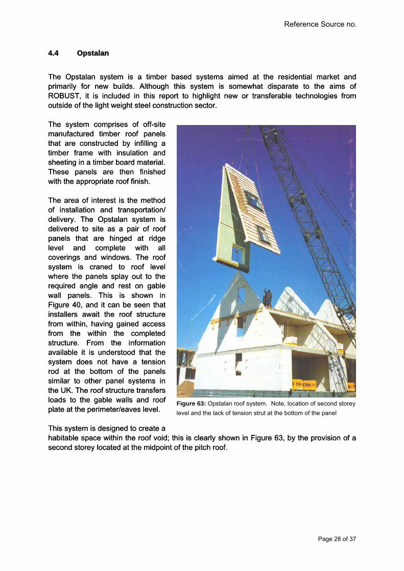
The Opstalan system is a timber based systems aimed at the residential market and primarily for new builds. Although this system is somewhat disparate to the aims of ROBUST, it is included in this report to highlight new or transferable technologies from outside of the light weight steel construction sector. The system comprises of off-site manufactured timber roof panels that are constructed by infilling a timber frame with insulation and sheeting in a timber board material. These panels are then finished with the appropriate roof finish.
The system comprises of off-site manufactured timber roof panels that are constructed by infilling a timber frame with insulation and sheeting in a timber board material. These panels are then finished with the appropriate roof finish.
Figure 63: Opstalan roof system. Note, location of second storey
level and the lack of tension strut at the bottom of the panel
The area of interest is the method of installation and transportation/ delivery. The Opstalan system is delivered to site as a pair of roof panels that are hinged at ridge level and complete with all coverings and windows. The roof system is craned to roof level where the panels splay out to the required angle and rest on gable wall panels. This is shown in Figure 40, and it can be seen that installers await the roof structure from within, having gained access from the within the completed structure. From the information available it is understood that the system does not have a tension rod at the bottom of the panels similar to other panel systems in the UK. The roof structure transfers loads to the gable walls and roof plate at the perimeter/eaves level.
The area of interest is the method of installation and transportation/ delivery. The Opstalan system is delivered to site as a pair of roof panels that are hinged at ridge level and complete with all coverings and windows. The roof system is craned to roof level where the panels splay out to the required angle and rest on gable wall panels. This is shown in Figure 40, and it can be seen that installers await the roof structure from within, having gained access from the within the completed structure. From the information available it is understood that the system does not have a tension rod at the bottom of the panels similar to other panel systems in the UK. The roof structure transfers loads to the gable walls and roof plate at the perimeter/eaves level. This system is designed to create a habitable space within the roof void; this is clearly shown in Figure 63, by the provision of a second storey located at the midpoint of the pitch roof.
This system is designed to create a habitable space within the roof void; this is clearly shown in Figure 63, by the provision of a second storey located at the midpoint of the pitch roof.
Page 28 of 37

DRAFT DRAFT
Reference Source no.
4.5 Lett-Tak 4.5 Lett-Tak
Lett-Tak is an industrial roofing system that utilises a hybrid panelised and truss configuration to enable rapid roofing on-site with approximately 1500m2 of roofing completed per day. Lett-Tak is an industrial roofing system that utilises a hybrid panelised and truss configuration to enable rapid roofing on-site with approximately 1500m2 of roofing completed per day. The system comprises of long spanning trusses in the order of 25m and insulated composite steel sandwich panels. Transport to site is similar to profile cladding and installation does require working at height as can be seen in Figure 64.
The system comprises of long spanning trusses in the order of 25m and insulated composite steel sandwich panels. Transport to site is similar to profile cladding and installation does require working at height as can be seen in Figure 64.
Figure 64: Installation of Lett-Tak roof system at height. The long span trusses
and composite sandwich panels are examples of transferable systems to the
residential and renovation sectors
Page 29 of 37

DRAFT DRAFT
Reference Source no.
4.6 Smartroof 4.6 Smartroof
This system is typical of the structural Insulated Panel (SIP) systems which are currently more energy efficient than steel intensive systems. However these systems are limited to use in low-rise residential buildings up to 3-4 storeys. SIP systems are not generally used in renovation, over-roofing scenarios. However they provide a relatively simple solution to the room-in-roof requirement.
This system is typical of the structural Insulated Panel (SIP) systems which are currently more energy efficient than steel intensive systems. However these systems are limited to use in low-rise residential buildings up to 3-4 storeys. SIP systems are not generally used in renovation, over-roofing scenarios. However they provide a relatively simple solution to the room-in-roof requirement. In the case of Smartroof, the system does not require rafters or trusses; rather the loads are transferred to gable walls and wall plates at eaves level. Each panel, which is constructed in a similar manner to the Opstalan system, has a tongue and groove arrangement longitudinally and interlocks with the panels either side to form a contiguous roof panel. Figure 65 shows the installation of a Smartroof system.
In the case of Smartroof, the system does not require rafters or trusses; rather the loads are transferred to gable walls and wall plates at eaves level. Each panel, which is constructed in a similar manner to the Opstalan system, has a tongue and groove arrangement longitudinally and interlocks with the panels either side to form a contiguous roof panel. Figure 65 shows the installation of a Smartroof system.
. . Figure 65: Room-in-roof scenario fulfilled with the use of timber SIP
Page 30 of 37

DRAFT DRAFT
Reference Source no.
4.7 Europe TwinTile / Kingspan Panel Systems 4.7 Europe TwinTile / Kingspan Panel Systems
Europe TwinTile is a factory pre-engineered lightweight steel intensive replacement for traditional clay, concrete or slate roofing tiles. The tiles are suitable for use with timber and steel roof structure for new build and flat-to-pitch support structure and framing systems. Kingspan has also launched its roof tiles insulated panel system which is suitable for new building and refurbishment of residential, commercial and industrial buildings. The external layer is a high performance polymer coated 0.7mm thick steel and internal 0.4mm thick steel with PU foam sandwiched between the two steel skins. The overall thickness ranges from 85 to 140mm thick with U-value between 0.45 and 0.20 W/m2K respectively. The range of traditional tile replacement systems available from TwinTile covers various applications; products include TwinTile, Thermo TwinTile, and MetalSlate.
Europe TwinTile is a factory pre-engineered lightweight steel intensive replacement for traditional clay, concrete or slate roofing tiles. The tiles are suitable for use with timber and steel roof structure for new build and flat-to-pitch support structure and framing systems. Kingspan has also launched its roof tiles insulated panel system which is suitable for new building and refurbishment of residential, commercial and industrial buildings. The external layer is a high performance polymer coated 0.7mm thick steel and internal 0.4mm thick steel with PU foam sandwiched between the two steel skins. The overall thickness ranges from 85 to 140mm thick with U-value between 0.45 and 0.20 W/m2K respectively. The range of traditional tile replacement systems available from TwinTile covers various applications; products include TwinTile, Thermo TwinTile, and MetalSlate. The TwinTile system is the original product of which the rest are derivatives. It is a two sheet Alu-Zinc (0.3mm) steel plate that is formed to replicate the look of individual roof tiles, but it has multiple tile profiles per unit as shown in Figure 66. The TwinTile has a polymer foil between the sheets to aid the production process and aid thermal resistance.
The TwinTile system is the original product of which the rest are derivatives. It is a two sheet Alu-Zinc (0.3mm) steel plate that is formed to replicate the look of individual roof tiles, but it has multiple tile profiles per unit as shown in Figure 66. The TwinTile has a polymer foil between the sheets to aid the production process and aid thermal resistance.
The Thermo TwinTile is a derived system of the TwinTile that has the added advantage of integral bonded thermal insulating foam, shown in Figure 67. This system is similar to a composite sandwich panel other than having a heavier profile.
The Thermo TwinTile is a derived system of the TwinTile that has the added advantage of integral bonded thermal insulating foam, shown in Figure 67. This system is similar to a composite sandwich panel other than having a heavier profile.
Figure 66: Roof covered with steel intensive TwinTile system
Figure 67: TwinTile installtion process and view of thermal insulation
Page 31 of 37

DRAFT DRAFT
Reference Source no.
4.8 Cool Roof Tiles 4.8 Cool Roof Tiles
Rising temperature resulting from urban heat island effect and global warming is a major challenge. Passive cooling techniques for reducing urban temperature and building internal heat gain to improve user comfort are imperative. Technological developments such as green roof, ground and convective cooling and, ventilation have proven extremely efficient in decreasing the need for mechanical cooling and improving indoor environmental conditions.
Rising temperature resulting from urban heat island effect and global warming is a major challenge. Passive cooling techniques for reducing urban temperature and building internal heat gain to improve user comfort are imperative. Technological developments such as green roof, ground and convective cooling and, ventilation have proven extremely efficient in decreasing the need for mechanical cooling and improving indoor environmental conditions. A recent development in the field of solar and heat protection is the cool roof system, which is the use of highly reflective coating to reduce surface temperature and internal heat gain. A cool roof has a higher solar reflectance (≥ 0.7) and higher thermal emittance (≥ 0.75) than a non-cool roof18. In simple terms, a cool roof reflects and emits the majority of the sun's heat instead of transferring it into the building. "Coolness" is measured by two properties, solar reflectance and thermal emittance19. Both properties are measured from 0 to 1 and the higher the value, the "cooler" the roof. Unlike conventional roofs, cool roofs stay at or near ambient temperatures even on the hottest summer day.
A recent development in the field of solar and heat protection is the cool roof system, which is the use of highly reflective coating to reduce surface temperature and internal heat gain. A cool roof has a higher solar reflectance (≥ 0.7) and higher thermal emittance (≥ 0.75) than a non-cool roof
18. In simple terms, a cool roof reflects and emits the majority of the sun's heat instead of transferring it into the building. "Coolness" is measured by two properties, solar reflectance and thermal emittance19. Both properties are measured from 0 to 1 and the higher the value, the "cooler" the roof. Unlike conventional roofs, cool roofs stay at or near ambient temperatures even on the hottest summer day.
The schematic presentation of heat transfer through a roof is shown in Figure 68. The surface temperature of a cool roof is up to 15oC lower when compared to a conventional material of the same colour20. Achieving this type of drop in roof surface temperature will reduce the overall heat gain through the roof and reduce a building’s annual cooling loads.
The schematic presentation of heat transfer through a roof is shown in Figure 68. The surface temperature of a cool roof is up to 15
oC lower when compared to a conventional material of the same colour20. Achieving this type of drop in roof surface temperature will reduce the overall heat gain through the roof and reduce a building’s annual cooling loads.
Cool coating technology is widely used in the USA and Australia on varieties of renovation and new build residential, commercial and industrial roof surfaces such as metal, clay and concrete tiles. The coating can be applied offsite or in-situ as shown in the Figures 69 & 70. In this application, the roof has the same visual appearance, but is much cooler. Thus it is possible to have relatively dark-coloured roofs with relatively “cool” properties.
Cool coating technology is widely used in the USA and Australia on varieties of renovation and new build residential, commercial and industrial roof surfaces such as metal, clay and concrete tiles. The coating can be applied offsite or in-situ as shown in the Figures 69 & 70. In this application, the roof has the same visual appearance, but is much cooler. Thus it is possible to have relatively dark-coloured roofs with relatively “cool” properties.
Figure 68: Typical Cool Roof Spray Installation19 Figure 70: Typical Cool Roof Spray Installation on clay tiles19
Figure 68: Heat transfer through roof19
Page 32 of 37

DRAFT DRAFT
Reference Source no.
4.9 Urban Roof 4.9 Urban Roof
Corus, in partnership with BASF has recently launched a new steel profile coated with the cool roof system called “Corus Colorcoat UrbanTM”, designed for the sustainable urban buildings. The product has a range of tonal colours suited for the urban fabric and a choice of variety of profiles to facilitate greater design freedom. The product is suitable for all roofing applications, both new build and refurbishment.
Corus, in partnership with BASF has recently launched a new steel profile coated with the cool roof system called “Corus Colorcoat UrbanTM”, designed for the sustainable urban buildings. The product has a range of tonal colours suited for the urban fabric and a choice of variety of profiles to facilitate greater design freedom. The product is suitable for all roofing applications, both new build and refurbishment. Colorcoat Urban™ is a low carbon roof material and it is 100% recyclable. The roof system has also undergone and passed stringent testing to BS6920 ‘Suitability of non metallic products for use in contact with water intended for human consumption’, supporting its use for rainwater harvest systems. The roof system facilitates simple, effortless and aesthetic integration of photovoltaic, solar thermal, passive solar heat collection and/or green roofs, all of which are intended to enable the designer to achieve even the most stringent of forthcoming legislation.
Colorcoat Urban™ is a low carbon roof material and it is 100% recyclable. The roof system has also undergone and passed stringent testing to BS6920 ‘Suitability of non metallic products for use in contact with water intended for human consumption’, supporting its use for rainwater harvest systems. The roof system facilitates simple, effortless and aesthetic integration of photovoltaic, solar thermal, passive solar heat collection and/or green roofs, all of which are intended to enable the designer to achieve even the most stringent of forthcoming legislation. Colorcoat Urban™ was incorporated on the recently opened BASF Creative Energy House (Figure 71) at the University of Nottingham, a sustainable housing project focusing on energy efficiency and affordability, using an array of innovative and sustainable materials.
Colorcoat Urban™ was incorporated on the recently opened BASF Creative Energy House (Figure 71) at the University of Nottingham, a sustainable housing project focusing on energy efficiency and affordability, using an array of innovative and sustainable materials.
Figure 71: Corus Colorcoat UrbanTM on the roof of BASF Creative Energy House
Page 33 of 37

DRAFT DRAFT
Reference Source no.
5. Related Research in Europe 5. Related Research in Europe
5.1 Prefabricated Systems for Low Energy Renovation of Residential Buildings 5.1 Prefabricated Systems for Low Energy Renovation of Residential Buildings
This project is highly relevant to ROBUST project particularly WP 4, though not material specific. The following are the extract from the project brief23: This project is highly relevant to ROBUST project particularly WP 4, though not material specific. The following are the extract from the project brief23:
Project ScopeProject Scope The project focuses on typical apartment blocks representing approximately 40 % of the European dwelling stock. However, appropriate single family homes are not excluded. The project concentrates on: Minimising the primary energy consumption (in the range of 30-50 kWh/(m2·year) for
heating, cooling and hot water, per gross floor area), Optimising the integration of solar energy use, Increasing living comfort by better space use, Assuring good thermal and acoustical comfort, good indoor air quality and daylighting
conditions, Assuring a fast, high quality and cost-effective construction process. Project Objective The objectives are the development and demonstration of an innovative whole building renovation concept for typical apartment buildings based on: Prototype, prefabricated roof systems with integrated HVAC, hot water and solar
systems, Highly insulated envelopes with integrated new distribution systems for heating, cooling
and ventilation. Advantages Achieving energy efficiency and comfort for existing apartment buildings comparable to
new advanced low energy buildings; Optimised constructions and quality and cost efficiency due to prefabrication; Opportunity to create attractive new living space in the prefabricated attic space and by
in-corporating existing balconies into the living space; A quick renewal process with minimised disturbances for the inhabitants.
Project Subtasks The project will be structured according to the following five Subtasks:
Page 34 of 37

DRAFT DRAFT
Reference Source no.
Project Status The project started in January 2007 and will finish end of June 2010. The last working meeting was held in April 7-9, 2008 in Munich (Germany), while the next working meeting is planned for October 20-22, 2008 in Belgium. Participants Portugal: University of Minho / Porto University Austria: AEE - Institute for Sustainable Technologies Belgium: Arcelor Research Centre Liege, University of Liège France: Saint-Gobain Insulation, Centre Scientifique et Technique du Bâtiment CSTB Sweden: Lunds tekniska högskola / Christer Nordström Architects Germany: Fraunhofer-Institute for Building Physics Czech Republic: ENVIROS / Brno University of Technology The Netherlands: Cauberg-Huygen Consulting Engineers Switzerland: Empa / HS Luzern / FHNW Basle Operating Agent The contact person on behalf of Swiss Federal Office of Energy is: Mr Mark Zimmermann, EMPA-ZEN, Überlandstrasse 129, CH 8600 Dübendorf, SWITZERLAND Tel: +41 (0) 44 823 4118 Fax: +41 (0) 44 823 4009 Email: [email protected]@empa.ch
Page 35 of 37

DRAFT DRAFT
Reference Source no.
6. Conclusion and Recommendation
This report provides an extensive review of the state of the art of various systems, both steel intensive (lightweight steel) and other material to facilitate knowledge transfer. The roof systems were also reviewed in terms of applications and capability in creating a habitable space, over roofing for both refurbishment and new build scenarios. For completeness, a relevant ongoing research project in Europe was briefly reviewed. The breadth of the systems reviewed (Table 1) can be broadly categorised as:
Panelised lightweight steel trusses Panelised composite lightweight steel panel or structural insulated panel (SIP) Modularised lightweight steel Moment resisting lightweight steel frame Novel roof tile/profile systems
The main findings of the review were that the majority of the steel intensive solutions in the market are mainly geared toward new build and refurbishment of existing building in terms of over roofing and conversion of flat-to-pitch roofs. These systems are mostly panelised lightweight steel trusses. The configurations of the steel trusses reviewed are based on traditional truss systems (see below) and constructed using Top-Hat section, C-section, U-section and/or proprietary sections. The reason for the wide spread use of the traditional truss configuration is the benefit of longer span capability compared to timber trusses. However, the configuration and spacing prohibit the provision of a room-in-roof solution.
Figure 72: Typical traditional truss systems available in the market Technically all the modular manufacturers across Europe should be able to provide fully furnished, steel intensive habitable roof systems for new build. One example is noted in this review. However, there is no steel solution for retrofitting of millions of existing timber roof trusses to create habitable roof space. There is a need for market research into the reasons for sparse availability of steel systems for creation of habitable roof solution for refurbishment application. Other non-truss systems have merits in terms of creating a habitable space for refurbishment. Systems such as the SmartRoof and Optalan SIP timber systems offer the largest and most efficient use of roof space for habitation. The use of steel structural insulated panels has been advocated and marketed by Fusion Building Solutions. There are opportunities for knowledge transfer in the use of composite timber cross walls for creating habitable roof. Concerning relevant research project, collaboration is strongly recommended with the low energy renovation project identified in Section 5 to avoid duplication of efforts and reinventing the wheel.
Page 36 of 37

DRAFT DRAFT
Reference Source no.
Page 37 of 37

DRAFT
Page 38 of 37
DRAFT
Reference Source no.
Reference 1. www.corus-hipoint.com 2. www.nuconsteel.com 3. www.gustrussfl.com 4. www.dibsa.co.uk 5. www.kingspanmetlcon.com 6. www.ayrshire.co.uk 7. www.ashandlacy.com 8. www.fusionbuildingsystem.com 9. www.resettesystems.com 10. www.metsec.co.uk 11. www.banro.co.uk 12. www.coverstructure.com 13. www.opstalan.nl 14. www.lett-tak.no 15. www.smartroof.co.uk 16. www.twintile.be 17. www.kingspanpanels.com/Products/Insulated-Roof-Systems/KS1000-RT---Roof-
Tile/Product-Information/Applications.aspx 18. Cool Roof Rating Council (CRRC): www.coolroofs.org 19. Pacific gas and electric company, Cool Roof Design Brief,
www.energydesignresources.com 20. Lawrence Berkeley National Laboratory, Heat Island Projects,
http://eetd.lbl.gov/HeatIsland/PROJECTS/ 21. High Albedo (Cool) Roofs, Codes and Standards Enhancement (CASE) Study, Pacific
Gas and Electric Company, November 17, 2000 22. Urban Roof: http://www.colorcoat-online.com/en/news/colorcoat_urban 23. Prefabricated Systems for Low Energy Renovation of Residential Buildings:
http://www.empa-ren.ch/A50.htm