review of superconducting rf technology for high-power...
TRANSCRIPT
Review of Superconducting RF Technologyfor High-Power Proton Linacs
K. C. D. CHAN, Los Alamos National Laboratory, USA; Henri Safa, CEA, Saclay, France;C. Pagani, INFN, Milano, Italy; M. Mizumoto, JAERI, Japan
Abstract
High-power proton linacs are efficient drivers forspallation neutron sources that have a wide variety ofresearch and transmutation applications. The use ofsuperconducting RF technology for these high-powerlinacs serves to increase their power efficiency and reducebeam loss. Recognizing these advantages, laboratoriesworldwide have initiated programs to developsuperconducting RF technology for such applications.This paper reviews existing technology developmentprograms and summarizes the status of superconductingRF technology for high-power proton linacs.
1 INTRODUCTIONHigh-power proton linacs can produce neutrons efficientlythrough spallation processes. The linac beam parametersare optimized for specific applications and target designs.Nominally, a high-current proton beam of 100 mA with abeam energy of 1 GeV will hit a target of high atomicnumbers such as lead and tungsten. More than twentyneutrons per proton can be produced for uses in researchand transmutation applications [1]. Research applicationsmainly involve the use of neutron scattering to investigatematerial properties [2]. Transmutation applicationsinclude the lifetime reduction of nuclear reactor wastes [3]and the production of tritium [4]. Most of theseapplications require linacs to operate in CW mode, withthe pulsed neutron source for research applications as anexception.
Although high-power proton linacs can be built withvarious technologies, there are two major advantages forbuilding them using superconducting (SC) RF technology[5]. First, SCRF linacs have high power efficiency thatis important for linacs having high beam power. Theyhave high power efficiency because the SC cavities havenegligible wall loss. Second, SCRF linacs have lessbeam loss than conventional linacs. Beam loss in protonlinacs is caused by the interception of beam halo by thebeam pipe. At high current, the level of ionizationradiation resulting from beam loss can create significantoperation and maintenance difficulties. The large beamaperture typical of SCRF cavities minimizes beam-halointerception and greatly alleviates the beam loss and theresulting ionization radiation.
Recognizing SCRF technology as the most promisingchoice for high-power linacs, laboratories in manycountries have initiated R&D programs to develop SCRF
technology specific for high-power proton linacs. Thetechnology development is mainly in the areas of β<1cavities, high-power couplers, cryomodule integration, andRF control. In this paper, we will briefly review thedevelopment programs around the world and the status ofthe technology development.
2. SCRF TECHNOLOGYDEVELOPMENT PROGRAMS
WORLDWIDESuperconducting RF R&D programs for high-powerproton linac are being carried out in many laboratoriesaround the world. This paper will describe the programsin the US, France, Japan, and Italy. We will brieflydescribe these programs and provide the references so thatthe readers can find more information. We will alsosummarize the status of development work in the areas ofcavities, couplers, cryomodule integration, and RFcontrol.
2.1 The APT Program in the US [6]
The US program was initiated at Los Alamos NationalLaboratory (LANL) in 1997. The program has beensupported by the Accelerator Production of Tritium (APT)Project, funded by Defense Programs of the USDepartment of Energy. Other programs that can make useof the developed technology include the AcceleratorTransmutation of Waste Project and the SpallationNeutron Source Project in the US.
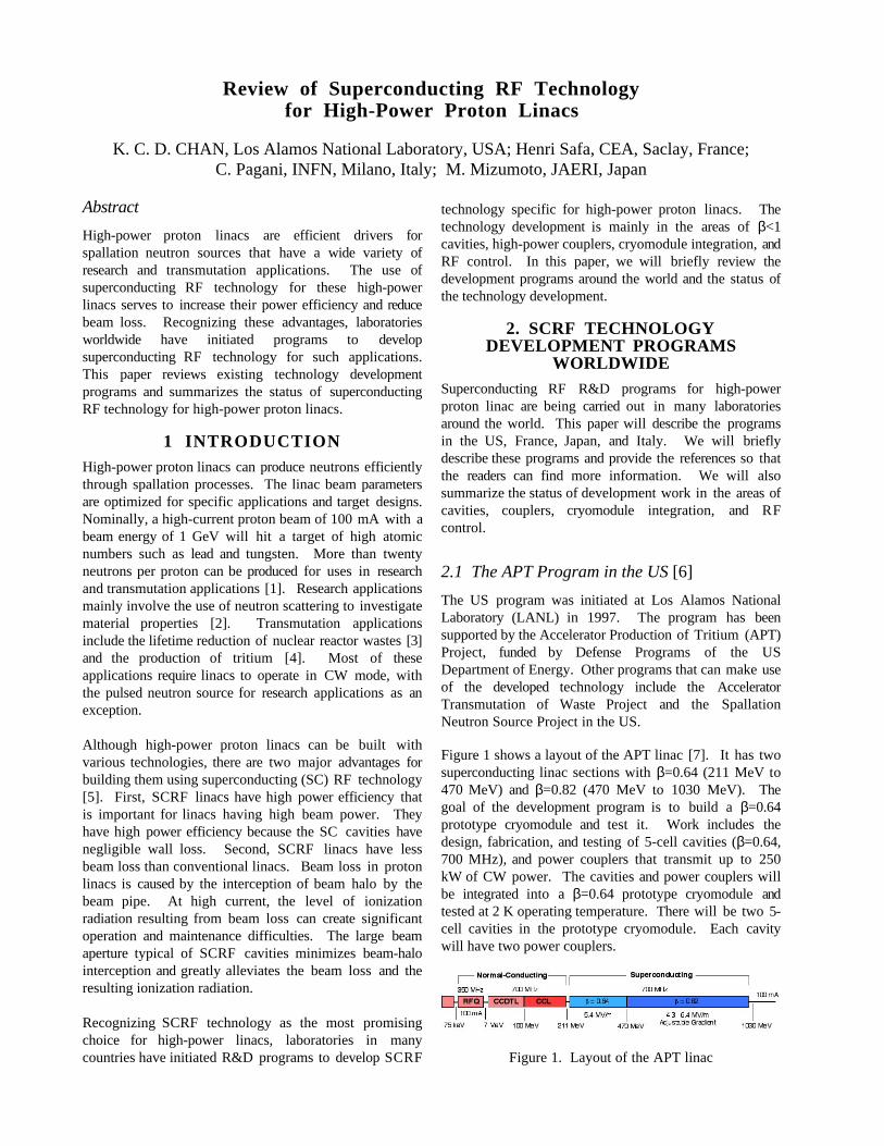
Figure 1 shows a layout of the APT linac [7]. It has twosuperconducting linac sections with β=0.64 (211 MeV to470 MeV) and β=0.82 (470 MeV to 1030 MeV). Thegoal of the development program is to build a β=0.64prototype cryomodule and test it. Work includes thedesign, fabrication, and testing of 5-cell cavities (β=0.64,700 MHz), and power couplers that transmit up to 250kW of CW power. The cavities and power couplers willbe integrated into a β=0.64 prototype cryomodule andtested at 2 K operating temperature. There will be two 5-cell cavities in the prototype cryomodule. Each cavitywill have two power couplers.
Figure 1. Layout of the APT linac
To date, the program has achieved the following:• Tests of β=0.48 and 0.64 single-cell cavities showed
that required fields (Eacc=5 MV/m) can be achievedwithout multipacting [8];
• A proton irradiation experiment of an operating SCcavity showed no degradation of SC-cavity propertiesup to 5x10¹⁵ protons/cm2 [9];
• Design and fabrication of 5-cell cavities have beencompleted [10];
• Power couplers have been designed and fabricated;They have been tested at room temperature to above 1MW of forward power [11];
• Cryomodule design was completed and fabrication hasbegun[12]; and
• Modification of the LANL SCRF facility wascompleted for processing and testing 5-cell cavities[13].
Five-cell-cavity and power-coupler tests are scheduled tobe completed in the year 2000. A test of the cryogenicdesign of the power coupler will also be completed in thesame year. In 2001, the cryomodule test will take place.
2.2 The ASH Program in France [14]
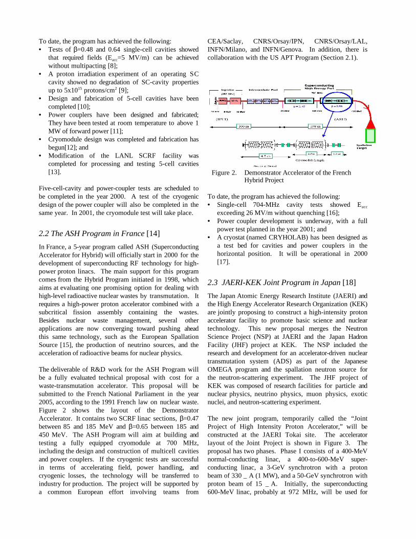
In France, a 5-year program called ASH (SuperconductingAccelerator for Hybrid) will officially start in 2000 for thedevelopment of superconducting RF technology for high-power proton linacs. The main support for this programcomes from the Hybrid Program initiated in 1998, whichaims at evaluating one promising option for dealing withhigh-level radioactive nuclear wastes by transmutation. Itrequires a high-power proton accelerator combined with asubcritical fission assembly containing the wastes.Besides nuclear waste management, several otherapplications are now converging toward pushing aheadthis same technology, such as the European SpallationSource [15], the production of neutrino sources, and theacceleration of radioactive beams for nuclear physics. The deliverable of R&D work for the ASH Program willbe a fully evaluated technical proposal with cost for awaste-transmutation accelerator. This proposal will besubmitted to the French National Parliament in the year2005, according to the 1991 French law on nuclear waste.Figure 2 shows the layout of the DemonstratorAccelerator. It contains two SCRF linac sections, β=0.47between 85 and 185 MeV and β=0.65 between 185 and450 MeV. The ASH Program will aim at building andtesting a fully equipped cryomodule at 700 MHz,including the design and construction of multicell cavitiesand power couplers. If the cryogenic tests are successfulin terms of accelerating field, power handling, andcryogenic losses, the technology will be transferred toindustry for production. The project will be supported bya common European effort involving teams from
CEA/Saclay, CNRS/Orsay/IPN, CNRS/Orsay/LAL,INFN/Milano, and INFN/Genova. In addition, there iscollaboration with the US APT Program (Section 2.1).
Figure 2. Demonstrator Accelerator of the FrenchHybrid Project
To date, the program has achieved the following:• Single-cell 704-MHz cavity tests showed Eacc
exceeding 26 MV/m without quenching [16];• Power coupler development is underway, with a full
power test planned in the year 2001; and• A cryostat (named CRYHOLAB) has been designed as
a test bed for cavities and power couplers in thehorizontal position. It will be operational in 2000[17].
2.3 JAERI-KEK Joint Program in Japan [18]
The Japan Atomic Energy Research Institute (JAERI) andthe High Energy Accelerator Research Organization (KEK)are jointly proposing to construct a high-intensity protonaccelerator facility to promote basic science and nucleartechnology. This new proposal merges the NeutronScience Project (NSP) at JAERI and the Japan HadronFacility (JHF) project at KEK. The NSP included theresearch and development for an accelerator-driven nucleartransmutation system (ADS) as part of the JapaneseOMEGA program and the spallation neutron source forthe neutron-scattering experiment. The JHF project ofKEK was composed of research facilities for particle andnuclear physics, neutrino physics, muon physics, exoticnuclei, and neutron-scattering experiment.
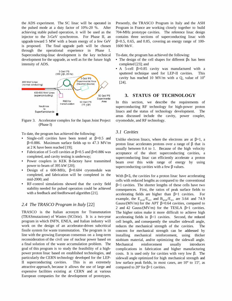
The new joint program, temporarily called the “JointProject of High Intensity Proton Accelerator,” will beconstructed at the JAERI Tokai site. The acceleratorlayout of the Joint Project is shown in Figure 3. Theproposal has two phases. Phase I consists of a 400-MeVnormal-conducting linac, a 400-to-600-MeV super-conducting linac, a 3-GeV synchrotron with a protonbeam of 330 _ A (1 MW), and a 50-GeV synchrotron withproton beam of 15 _ A. Initially, the superconducting600-MeV linac, probably at 972 MHz, will be used for
the ADS experiment. The SC linac will be operated inthe pulsed mode at a duty factor of 10%-20 %. Afterachieving stable pulsed operation, it will be used as theinjector to the 3-GeV synchrotron. For Phase II, anupgrade toward 5 MW with a beam energy of a few GeVis proposed. The final upgrade path will be chosenthrough the operational experience in Phase I.Superconducting-linac development is the key technicaldevelopment for the upgrade, as well as for the future highintensity of ADS.
Figure 3. Accelerator complex for the Japan Joint Project(Phase I)
To date, the program has achieved the following:• Single-cell cavities have been tested at β=0.5 and
β=0.886. Maximum surface fields up to 47.3 MV/mat 2 K have been reached [19];
• Fabrication of 5-cell cavities at β=0.5 and β=0.886 wascompleted, and cavity testing is underway;
• Power couplers in KEK B-factory have transmittedpower to beam of 395 kW [20];
• Design of a 600-MHz, β=0.604 cryomodule wascompleted, and fabrication will be completed in themid-2000; and
• RF-control simulations showed that the cavity fieldstability needed for pulsed operation could be achievedwith a feedback and feedforward algorithm [21].
2.4 The TRASCO Program in Italy [22]
TRASCO is the Italian acronym for Transmutation(TRASmutazione) of Wastes (SCOrie). It is a two-yearprogram in which INFN, ENEA, and Italian industry willwork on the design of an accelerator-driven subcriticalfissile system for waste transmutation. The program is inline with the growing European consensus on a long-termreconsideration of the civil use of nuclear power based ona final solution of the waste accumulation problem. Thegoal of this program is to study the feasibility of a high-power proton linac based on established technologies, andparticularly the CERN technology developed for the LEP-II superconducting cavities. This is an extremelyattractive approach, because it allows the use of large andexpensive facilities existing at CERN and at variousEuropean companies for the development of prototypes.
Presently, the TRASCO Program in Italy and the ASHProgram in France are working closely together to build704-MHz prototype cavities. The reference linac designcontains three sections of superconducting linac withβ=0.5, 0.65, and 0.85, covering an energy range of 100-1600 MeV.
To-date, the program has achieved the following:• The design of the cell shapes for different βs has been
completed [23]; and• A 5-cell β=0.85 cavity was manufactured with a
sputtered technique used for LEP-II cavities. Thiscavity has reached 10 MV/m with a Qo value of 109
[24].
3. STATUS OF TECHNOLOGYIn this section, we describe the requirements ofsuperconducting RF technology for high-power protonlinacs and the status of technology development. Theareas discussed include the cavity, power coupler,cryomodule, and RF technology.
3.1 Cavities
Unlike electron linacs, where the electrons are at β=1, aproton linac accelerates protons over a range of β that isusually between 0.4 to 1. Because of the high velocityacceptance of the short superconducting cavities, asuperconducting linac can efficiently accelerate a protonbeam over this wide range of energy by usingsuperconducting cavities with a few β values.
With β<1, the cavities for a proton linac have acceleratingcells with reduced lengths as compared to the conventionalβ=1 cavities. The shorter lengths of these cells have twoconsequences. First, the ratios of peak surface fields toaccelerating fields are higher than β=1 cavities. Forexample, the Epeak/Eacc and Bpeak/Eacc are 3.64 and 74.9Gauss/(MV/m) for the APT β=0.64 cavities, compared to2 and 42 Gauss/(MV/m) for the TESLA β=1 cavities.The higher ratios make it more difficult to achieve highaccelerating fields in β<1 cavities. Second, the reducedcell length, and consequently the smaller sidewall angle,reduces the mechanical strength of the cavities. Theconcern for mechanical strength can be addressed byinstalling mechanical reinforcement, using thickerniobium material, and/or optimizing the sidewall angle.Mechanical reinforcement usually introducescomplications in fabrication and higher manufacturingcosts. It is used only for cavities with very low β. Thesidewall angle optimized for high mechanical strength andlow surface peak fields, in most cases, are 10º to 15º, ascompared to 20º for β=1 cavities.
Because of the power transmission limitation of powercouplers, the Eacc required in high-power proton linacs isbetween 5-10 MV/m. This modest value of Eacc iscomfortably reached using the present standard fabricationand processing techniques for superconducting cavitieswith high-pressure water rinsing. Heat treatment is neededonly at 800º C to minimize the chance of hydrogeneffects.
In the APT program, 700-MHz β=0.48 and β=0.64 single-cell cavities have been tested. The cell shape wasoptimized, keeping the peak surface electric fields below16 MV/m. Results from vertical cavity tests showed thatan Eacc of 5 MV/m with a Qo of 5x10⁹ were achieved(Figure 4). Six 5-cell cavities have been built, and testresults of these cavities will be available beginning in thewinter of 1999. The single-cell cavities were built withmechanical reinforcement, and the 5-cell cavities werebuilt without reinforcement. In the last two years, thesuperconducting RF facility in Los Alamos NationalLaboratory has been modified to process and test 5-cell,700-MHz cavities.
Figure 4. Results of APT single-cell cavity test (β=0.48)
Figure 5. Results of ASH single-cell cavity test (β=0.65)
In the French ASH program, the cell shape was designedusing a conservative value of 50 mT for the peak surfacemagnetic field. Single-cell cavities with β=0.65 were
fabricated and tested in a vertical cryostat. Results showedexcellent performance, reaching an accelerating field of 26MV/m without quenching, at a corresponding peak surfacemagnetic field of 1230 gauss. The test results are shownin Figure 5, where the quality factor Qo is plotted as afunction of the accelerating field. In addition, it has beenshown that a heat treatment at 800°C would be required incavity processing because the Qo degradation by more thana factor of 30 is observed due to the hydrogen effect. The5-cell cavity design is now completed. Two 5-cell 700-MHz cavities will be fabricated and tested in the year2000. As for cavity testing, besides the standard verticaltest, a special horizontal cryostat named CRYHOLAB isin fabrication and should be operational for testing 700-MHz multicell cavities in 2000. Dedicated infrastructures,including a cleanroom facility, chemical-polishingfacility, and high-pressure-rinsing system, are also beingmodified to support this program.
In the Japanese Joint Program, two β=0.5 single-cellcavities and one β=0.886 single-cell cavity of 600 MHzhave been fabricated. The cell shapes have been designedto keep the peak surface electric field below 20 MV/m.Fabrication processes such as cold rolling, electron beamwelding, and surface treatment (barrel polishing,electropolishing heat treatment at 750°C and high-pressurewater rinsing at 8 MPa) have been performed based on theKEK experience for the 500-MHz TRISTAN cavity.Vertical tests have been conducted to examine the RF andmechanical properties. Figure 6 shows results of theperformance test of β=0.5 cavities. Maximum peaksurface fields of 44 MV/m and 47.3 MV/m at 2 K wereachieved for β=0.5 and β=0.886, respectively. Two 5-cellcavities with β values of 0.5 and 0.886 were alsofabricated. After pretuning and surface treatment, the firstvertical test of a 5-cell cavity was performed.
Figure 6. Results of Japanese single-cell cavitytest (β=0.5)
In the Italian TRASCO Program, a five-cell β=0.85 704-MHz structure produced using the standard CERN processfor making the LEP cavities has been tested. At 4.5 K,
the cavity reached the design goal of Eacc=5.5 MV/m witha Qo value of 2.5x10⁹. The ultimate field, which waslimited by the available RF power, was 10 MV/m with aQo value of 109. The Qo value of the cavity at 1 MV/mwas 5.6x10⁹. The same values of quality factors and fieldswere obtained for a single-cell cavity.
3.2 Power Couplers
The power coupler is the most challenging component ina high-power proton linac because hundreds of kilowattsof CW power must be transmitted to the beam throughthese couplers. Power couplers have been used at powerlevels at tens of kW. It is only recently that we havepower couplers operating at the levels needed for a high-power proton linac. These high-power couplers includethe waveguide couplers at CESR and the coaxial couplersat KEKB, transmitting, respectively, 260 and 390 kW ofCW power to the beam. Presently, all coupler designschosen for high-power proton linacs are of the coaxialtype because of compactness and large coupling range.
To design a power coupler for a high-power linac, thereare special considerations because of the high power thatis transmitted. First, we should push the multipactingthreshold beyond the operating power levels. Recentresults have shown that the multipacting thresholds in acoaxial line increase with RF frequency to the fourthpower [25]. One can, therefore, achieve a highermultipacting threshold by choosing a slightly higher RFfrequency. Second, we need to keep the RF losses low ina power coupler by minimizing mismatches and choosingmaterials and surface-preparation techniques that give highRF surface conductance. We must also closely watch thecooling and heat load of the couplers because the loads aremore significant when hundreds of kWs are transmitted.Third, coupling to the cavity field should be high andvariable. A high coupling coefficient is required becauseof the high beam loading. A variable coupling is neededbecause the cavity external-Q required to accelerate beam atdifferent proton beam energies is different. Fourth, weneed a robust design for RF windows operating at thesame power levels.
In the US APT Program, the power couplers have beendesigned for 210 kW transmitted to the beam. Two powercouplers are required to supply each cavity with 420 kWof power. The couplers have dual coaxial ceramic (Al2O3)warm windows that are manufactured by klystronsuppliers. These windows have been tested to 1 MW.The couplers have been tested on a room-temperature teststand to above 1 MW of transmitted power [11,26]. Areflected-power test and a cold test using a LN2 cold jacketare underway.
In the French ASH Program, power couplers capable ofhandling more than one hundred kW are needed for theDemonstrator Project. The power requirement will exceed300-kW CW for the final Hybrid prototype. A newcoupler is being designed in collaboration with LosAlamos, aiming at the high level of 300-kW CW,integrating in the design the important requirements ofreliability and easy replacement. The present schedule forthe coupler development is to perform a first test at anintermediate power of 80 kW in the year 2000 and a fullpower test in 2001.
In the Japanese Joint Program, the power-coupler designis based on the KEKB design that recently transmitted 390kW of CW power to the beam.
3.3 Cryomodules
Cryomodules used in SCRF high-power proton linacs donot have special design requirements. They can benefitfully from the existing cryomodule design experience.
Cryomodules designed for high-power proton linacs areusually short, containing only up to four cavities, becausemagnetic quadrupoles (room-temperature types as preferredin most linac designs) are needed to interlace with thecavities to provide stronger transverse focusing needed forgood beam dynamics. Short cryomodules also allows theinstallation of more frequent beam diagnostics to assurethe achievement of good beam matching to linacs. Forhigh-power coupler performance, the assembly of powercouplers to cryomodules is usually better performed in acleanroom.
In the US APT Program, a cryomodule has been designedbased on the CERN LEP-II design. The cryomodule isbeing fabricated and will be tested beginning in the winter2000.
In the French ASH Program, the cryomodule design workwill start next fiscal year. Integration of final cavities andcouplers is planned in 2002, and the complete test will beperformed in 2003. Industry will be involved at an earlystage in order to be ready for fabrication if the hybridproject were to be approved in 2004.
In the Japanese Joint Project, the cryomodule design workfor the 600-MHz β=0.604 cavity has been performed tomake the complete performance test for fabricationtechnique and thermal, electrostatic, and mechanicalproperties. The fabrication of the cryomodule will becompleted in the middle of 2000. A new building for ahorizontal cavity test is under construction, andinfrastructure for the test, including assembly room, RFpower source, liquid-helium supply, and x-ray shield isbeing prepared simultaneously.
3.4 RF Control
Phase and amplitude controls of cavity fields are veryimportant for high-power proton linacs in order tominimize beam-halo formation. The cavity fields have tobe stabilized under the influence of microphonics andLorentz-force detuning (in the case of pulsed operation).RF control is further complicated by the use of oneklystron to supply multiple cavities, a scheme to reducethe cost of RF systems. Usually, the klystron iscontrolled by feedback and feedforward techniques using asignal that represents the sum of the fields of cavitiespowered by the klystron. The sum of the fields must becontrolled to one degree in phase and one percent inamplitude.
In the French ASH Program, work has been done toconsider the possibility of using a low-cost RF systemthat allows the powering of a single cavity with oneklystron, and consequently enhancing cavity field control.The cost is minimized by using a common power supplyfor the klystrons.
The technology for controlling cavity fields under theinfluence of Lorentz-force detuning and microphonics forpulsed operation has been demonstrated for the electronlinac at the TESLA Test Facility linac [27] and will beadapted for use in proton linacs. In the Japan JointProject, high accuracy in cavity control is required toinject into the 3-GeV synchrotron. An RF-system modelis constructed based on the MATLAB/SIMULINK code.The model uses I/Q control model and PID feedback andfeedforward controllers. Simulations have been performedusing a cavity design at 600 MHz, β=0.604, a 3-mm wallthickness. The optimum PID parameters are calculated fordifferent controller delay times. Simulation resultsshowed that, with influence of the Lorentz detuning, afield stability of less than ±1% and ±1° is achieved with adelay time of 20 µs.
4. SUMMARYHigh-power superconducting RF proton linacs are thepreferred drivers for future neutron sources for neutron-scattering and transmutation technologies. R&Dprograms have been established in the US, France, Japan,and Italy to develop technology needed for these linacs.These programs have so far successfully pushed thefrontier of the SCRF technology. Single-cell cavity testswith β<1 have shown that the required cavity performancecan easily be obtained. Results of multicell cavity testsare beginning to become available. Power couplers havebeen the most challenging part of the technology for high-power superconducting RF proton linacs. In the last year,we have seen power couplers that can transmit the requiredhundreds of kW of CW power. In the next two years, we
will see the testing of prototype cryomodules, the basicbuilding blocks of superconducting RF linacs, with fullyfunctioning cavities and power couplers.
5. ACHNOWLEDGEMENTThe US APT Program is funded by the Defense Programof the US Department of Energy. The authors also wouldlike to thank Dan Rusthoi and George Lawrence forreading the manuscript.
6. REFERENCE1. S. O. Schriber, Survey of Proposed High Intensity
Accelerators and their Application, Proceedings of the1994 EPAC, p. 213.
2. K. Bongardt, M. Pabst, and A. Letchford, High IntensityInjector Linacs for Spallation Sources, Proceedings ofthe 1998 LINAC Conference, Chicago.
3. C. Rubia and J. A. Rubio, A Tentative ProgrammeTowards a Full Scale Energy Amplifier, CERN/LHC/96-11 (EET).
4. P. W. Lisowski, The Accelerator Production of Tritium(APT) Project, Proceedings of the 1997 PAC, Vancouver,BC, Canada, 1997.
5. K. C. D. Chan, G. P. Lawrence, and J. D. Schneider,Development of RF Linac for High-current Applications,NIM B 139 (1998) 394-400.
6. K. C. D. Chan, et al., Engineering Development ofSuperconducting RF Linac for High-Power Applications,Proceedings of the 6th EPAC, Stockholm, 1998.
7. G. P. Lawrence, High-Power Proton Linac for APT; Statusof Design and Development, Proceedings of LINAC’98,Chicago, 1998.
8. W. B. Haynes, et al, Medium-Beta SuperconductingCavity Tests At Los Alamos National Lab For High-Current, Proton Accelerators, Proceedings of the 8th
Workshop on RF Superconductivity, Abano Terme(Padova), Italy, 1997.
9. B. Rusnak, In-Situ Proton Irradiation and Measurementof Superconducting RF Cavities under CryogenicConditions, Proceedings of 1997 PAC, Vancouver, BC,Canada, May, 1997.
10. S. Atencio, et al, Design, Analysis, and Fabrication OfThe APT Cavities, Proceedings of the 1999 PAC, NewYork City, NY, 1999, p. 962.
11. W. B. Haynes, et al, High-Power Coaxial Coupler Designand Testing, this workshop.
12. M. J. Fagan, et al, Engineering Analysis of the APTCryomodules, Proceedings of the 1999 PAC, New YorkCity, 1999.
13. D. J. Katonak and B. Rusnak, Superconducting RF LabFacility Upgrades at Los Alamos, ibid.
14. H. Safa, A Superconducting Proton Linac for WasteTransmutation, this workshop.
15. The European Spallation Source Study, vol. 1 - 3, March1997.
16. J. L. Biarrotte, et al, 704 MHz Superconducting Cavitiesfor A High Intensity Proton Accelerator, this workshop.
17. H. Saugnac, et al, CRYHOLAB, A New Horizontal TestCryostat for SCRF Cavities, this workshop.
18. Y. Yamazaki and M. Mizumoto, Accelerator Complex forthe Joint Project of KEK/JHF and JAERI/NSP,Proceedings of the 1999 PAC, New York City, 1999.

19. N. Ouchi, et al, Development Of SuperconductingCavities for High Intensity Proton Accelerator at JAERI,Proceedings of 1998 Applied SuperconductingConference, Palm Desert, 1998.
20. T. Furuya, et al, recent Status of the SuperconductingCavities for KEKB, this workshop.
21. E. Chishiro, et al, Study of RF Control System forSuperconducting Cavity, Proceedings of the 12th
Symposium on Accelerator Science and Technology,Wako, Japan, 1999.
22. C. Pagani and Paolo Pierini, High Power CWSuperconducting Linacs For Nuclear Waste Processing,Proceedings of the 1999 Cryogenic EngineeringConference, Montreal, 1999.
23. D. Barni, et al, SC Beta Graded Cavity Design for aProposed 350 MHz Linac For Waste Transmutation andEnergy Production, proceedings of EPAC 98,Stockholm, 1998.
24. E. Chiaveri, et al, Production And Test of The PrototypeBeta 0.85 Five Cell Cavity For The TRASCO Project,this workshop
25. E. Somaersalo, et al, Proceedings of the 1995 PAC,Dallas, 1995.
26. E. Schrimerer, et al, Thermal and Mechanical TestingStatus of the SCRF Power Coupler for the APTAccelerator, this workshop.
27. S. Simrock, Advances In RF Control for High Gradients,this workshop.