review of testing protocols for precast concrete ... structural components.pdf · 1 abstract: this...
TRANSCRIPT
REVIEW OF TESTING
PROTOCOLS FOR
PRECAST CONCRETE
STRUCTURAL
COMPONENTS
IIT KANPUR

1
Abstract:
This report presents a literature survey on the testing methods of precast concrete constructions
in the past and recent years. Important articles are selected for review considering various
scenarios of construction to provide an outlook in loading protocols available for precast
construction practices around the globe.
Introduction:
In a world of perennially burgeoning population with colossal demand for sustainable
infrastructure, rapid urbanization is the only key to keep the pace. Owing to this growing need of
rapid construction, the concept of prefabricated or precast structural component has taken over
the conventional practices. Precast construction has provided several advantages like structural
efficacy, reduced cost, optimum material usage, fast construction, quality improvement and
adaptability due to better batching and quality control in the factory environment. Different
components of precast concrete structures are shown in the Fig. 1A.
However, during seismic events, the performance of precast structures are not very well
established with reliable performance evidence. Past earthquakes events have shown that more
modification in precast concrete design and detailing is needed in order to make it earthquake
resistant. In this context, this paper presents a detailed state of the art literature review on precast
structure and elements in order to provide a brief overview on present scenarios in precast
concrete design.
Fig. 1A: Precast concrete structure components (http://www.mapaprecast.org/)

2
Experimental and Numerical Research in Precast Concrete:
1. Bending Testing Protocol of Precast Beams (Ref: Precast.org)
Objective:
To determine the design load and the beam’s performance in handling beyond the typical design
load, as well as offering advantages over other systems - advantages like lighter weight and
insulation.
Fig.1 shows the load testing of the beams and the midspan deflection is measured according to
the mounted weights. Fig.2 shows the beam which is having very shallow depth and four stems,
designed to be double-T. The stems consists of prestressed bars and the flange incorporates mild
reinforcements.
Fig. 1: Maximum Load Testing in Precast Beams (Precast.org)
Fig.2: 8 ft wide Prestressed Beam (Precast.org)

3
The flange is prestressed by strands which are ½-in.-diameter and it was stressed to 31 kips. 2-ft-
long No. 3 bars at 18-in. c/c is used a reinforcement in the flange. For the test, two planks were
placed side by side and a 2 in. topping was poured over them, which is shown in Fig.3.
Fig.3: Cross section of the Test Beam (Precast.org)
Fig.4: Test setup with panel span length of 25 ft, 6 in (Precast.org).
For testing purpose, the topped plank is mounted onto concrete blocks so that the clear span
becomes 25 ft. 6 in. The ends were supported by urethane bearing pads which is shown in Fig.4.
Testing Procedure:
Stage 1: The beam is loaded with ultimate design load which is generally used in the residential
construction. The deflection is measured in the mid-point due to this ultimate moment
immediately after loading, and again after 136 hours. Afterwards, the loading is gradually
increased beyond the ultimate design load until the beam is failed. In this case, the gradual
increment in loading is stopped just before catastrophic failure. But if the beam had a deflection
of more than 8 inch, large cracks is noticed throughout the beam.

4
Stage 2: Unlike the stage 1, the loads will not be applied only in the center. As the maximum
design moment is known, the loads are distributed over the beam so that the maximum moments
becomes equal to the maximum design moment. So the load is mounted gradually and the
behaviour of beam i.e. deflection and crack initiation is noted. The step of load mounting is
shown in Fig.5.
Fig.5: Steps of mounting the loads (Precast.org)
Now for both the stages, the deflection and the load where crack is appearing and propagating is
noted which is shown in Figs.6 and 7.

5
Fig.6: Deflection measurement of beam (Precast.org)
Fig.7.1: Crack Initiation (Precast.org) Fig.7.2: Crack at Ultimate load (Precast.org)
This test is executed by Northeast Precast in July 2012. As the beam length and the specification
is different in our cases than the Northeast Precast test, so there data cannot be used directly. The
test should be done independently for our cases according to the test procedure.
2. Pseudo-dynamic testing of Structural System (Negro et al., 2013)
The specimen structure was a three storey full scale precast building having two 7 m bays in both
the horizontal direction which is shown in Fig. 8a. The plan of the building is 15 m X 16.25 m
and the height of the structure is 10.9 m. The floor to floor heights of 1st, 2nd and 3rd level are
3.5 m, 3.2 m and 3.2 m respectively. The experimental setup is shown in Fig.8b

6
Fig.8a: Model of the Structure Fig.8b: Experimental Model (Negro et al., 2013)
(Negro et al., 2013)
Description of the structural system:
The effectiveness of four different structural precast systems is investigated experimentally. The
behaviour of a series of parameters, several types of mechanical connections and the presence or
absence of shear walls along with the framed structure is assessed.
Prototype 1: In this case, two shear walls are connected to the structure. As all the beam-column
connections of the structure is hinged, the precast shear walls are used to increase the stiffness.
Typical Fig. of this prototype is shown in Fig.9a.
Prototype 2: Thes shear walls were removed from the structure and it is the most vulnerable and
flexible prototype compared to others. The beam-column connection is achieved by shear
connectors (dowel bars), The columns in this flexible structure were expected to behave like
cantilevers. The prototype 2 structure is shown in Fig.9b.
As only the beam-column hinge joint is not suffice for the structure to stand an earthquake, the
strengthening of the joints is absolutely necessary. A new connection system is proposed in the
article of Negro et al. 2013, where the beam column hinge joint is integrated with a dry
connection. It can emulate the performance of a moment resisting frame. The performance of this
new connection is investigated in the third and fourth structural configurations. As in the cast in
situ cases, the longitudinal reinforcement crosses the joint, a new steel device is embedded in the
precast element which connects the columns and beams. To fill the small gaps between beams
and columns, a special mortar was used.

7
Prototype 3: The special connection was only used at the third floor. It means that the emulated
moment connection is only achieved in the third floor which is shown in Fig.9c
Prototype 4: The connection system was activated in all beam–column joints which is shown in
Fig. 9d
Fig.9a: Prototype 1- Shear walls and Fig. 9b: Prototype 2: Hinged
hinged beam–column joints Beam-column joints
(T=0.3 Sec) (Negro et al., 2013) (T=1.09 Sec) (Negro et al., 2013)
Fig.9c: Prototype 3- Hinged beam- Fig.9d: Prototype 4- Emulative
column joints at the 1st and Beam Column Joints
2nd floor and emulative at the 3rd (T=0.66 Sec) (Negro et al., 2013)
(T=1.08 Sec) (Negro et al., 2013)
Input motion selection:
The reference input motion used in the PsD tests is a unidirectional 12s long-time history, shown
in Fig. 10a for a PGA of 1.0 g. The selected ground motion is from real accelerogram (Tolmezzo
1976) modified to fit the Eurocode 8 (EC8) response spectrum type B all over the considered
frequency interval. Fig. 10b illustrates the spectra of the modified EW component of Tolmezzo

8
recording and the EC8 specification. The accelerogram was scaled to the chosen peak ground
accelerations of 0.15 g for the serviceability limit state, and 0.30 g for the no-collapse limit state
Fig. 10a: Input Motion - scaled to 1g Fig. 10b: Modified Response Spectra
(Negro et al., 2013) (Negro et al., 2013)
Result:
Prototype 1: As the two stiff precast shear walls were present in prototype 1, it was very effective
in limiting the maximum inter storey drift ratios for both ultimate limit state as well as
serviceability limit state.
Prototype 2: As the prototype 2 was very flexible, the effect of the higher modes highly
influenced the seismic response of prototype 2.
● It lead to large force demand in the joints in the nonlinear regime.
● The hinged beam column joints was deformed excessively, so the 1% drift limitation was
exceeded.
● Though the connection movement is significant, no significant damage was observed in
the structural members.
Prototype 3: After obtaining the seismic test results of prototype 3, it was observed that the
emulative beam-column joint installed only at the top floor was not very effective.
● The effect of higher modes is also significant.
Prototype 4: When the emulative beam-column joint installed in every floor, the performance of
the connection system was quite effective.
Though flexural cracking is observed in the ground floor columns, no considerable damage is
structural members was perceived.
3. Pseudo-dynamic testing - the Behaviour of Connection (Bournas et al., 2013)
Pin Joint Connection: A typical pin joint connection in shown in fig.11

9
● This type of connection is able to transfer the axial and shear forces for seismic as well as
gravity forces. Also it can transfer the possible uplifting forces due to overturning.
● This connection cannot transfer moment and torsion, but in reality perfect hinge joint is
impossible to simulate, so small amount of bending moment is transferred by this type of
joint.
Fig.11a: Seating of a secondary Fig. 11b: Central Beam Column Joint
beam on the column capita (Bournas et al., 2013)
(Bournas et al., 2013)
Fig.11c: Detail of a pinned beam–column Fig.11d: Special dowels with increased
joint connection (Bournas et al., 2013) diameter at the critical section
(Bournas et al., 2013)
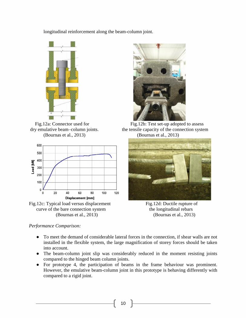
Emulative Beam column Joint Connection:
● This type of joint emulates the performance of moment resisting connection.
● An new ductile system is embedded in the precast element to provide the continuity of
10
longitudinal reinforcement along the beam-column joint.
Fig.12a: Connector used for Fig.12b: Test set-up adopted to assess
dry emulative beam–column joints. the tensile capacity of the connection system
(Bournas et al., 2013) (Bournas et al., 2013)
Fig.12c: Typical load versus displacement Fig.12d: Ductile rupture of
curve of the bare connection system the longitudinal rebars
(Bournas et al., 2013) (Bournas et al., 2013)
Performance Comparison:
● To meet the demand of considerable lateral forces in the connection, if shear walls are not
installed in the flexible system, the large magnification of storey forces should be taken
into account.
● The beam-column joint slip was considerably reduced in the moment resisting joints
compared to the hinged beam column joints.
● For prototype 4, the participation of beams in the frame behaviour was prominent.
However, the emulative beam-column joint in this prototype is behaving differently with
compared to a rigid joint.

11
4. Seismic tests of precast concrete, moment resisting frames and connections (Xue et al., 2010)
Xue at al. (2010) tested the behaviour of precast concrete connections in a typical moment frame
under cyclic loading protocol. In this study, four types of connections were investigated against
cyclic loading in both force and displacement control strategies.
Connection types:
Exterior connection(PCJ-1)
Interior connection(PCJ-2)
T connection(PCJ-3)
Knee connection(PCJ-4)
Description of the structural system:
Experiments comprise four precast concrete connections including half scale, two storey, two-
bay precast moment-resisting frame. Selected precast concrete connections of the frame model
are taken from a six storey rectangular prototype building shown in the Fig.13. All the
connections are designed with strong column-weak beam philosophy.
Fig 13.Prototype building structure based on the Chinese design code
(Xue et al., 2010)
Specimens
Specimen PCJ-1 and PCJ-2 are emulative of an interior and exterior connection in the 1st storey.
Specimen PCJ-3 and PCJ-4 represented a T and a knee connection in the top storey. All of the
precast concrete connections consisted of a composite concrete beam and a cast-in-place
concrete column.

12
Fig 14.Different specimens and different structural boundary conditions
(Xue et al., 2010)
Loading Protocols:
For first two specimens, the constant axial load of 10000 kN was applied at the top of the column
with an actuator to consider P-delta effect. Axial compressive ratio was taken as 0.4 and 0.3 for
specimen PCJ-1 and PCJ-2 respectively. Lateral cyclic loading was applied at the top column
with a horizontal load of 3000 kN. Loading process for PCJ-3 and PCJ-4 are similar except the
omission of axial load in column.
The frame model named as PCF-1 was tested under constant vertical loads (axial comp. ratio of
0.3 and for the exterior columns 0.4) representing the axial load due to live and dead loads.
A hydraulic actuator mounted to a rigid reaction frame is used to provide lateral force in the
frame. A whiffletree is used to maintain a lateral force distribution with a shape of inverted
triangle resembling the seismic force distribution. Lateral loads are provided in the first two
levels of the structure. Ratio of these loads was maintained constant with a value of 2.0. Also the
test is done for both positive and negative direction of loading. Fig. 15 shows the loading
diagram in the following.

13
Fig. 15 Loading applied the structure to emulate P-delta effects during earthquake
(Xue et al., 2010)
The loading protocol is divided into two distinctive regimes with a force controlled and a
displacement-control parts. It consisted of displacement cycles of increasing magnitude at 0.5%-
story-drift increments, with three cycles applied at each new drift level.
Fig. 16 Force and displacement controlled loading history (Xue et al., 2010)

14
Instrumentations:
Force and displacements were kept on track using load cells and linear variable-differential
transducers (LVDTs), respectively. Strain gauges are mounted on strategic locations if the
longitudinal and transverse reinforcements of the columns and beams.
Results:
Fig. 17 hysteric response of different specimens (Xue et al., 2010)
Fig. 18 Comparison of secant stiffness for specimens and building frame (Xue et al., 2010)

15
Fig. 19 Damage scenarios of four different specimens of the building frame (Xue et al., 2010)
Conclusion:
Test results revealed that the four precast concrete connections exhibited a strong column-
weak beam failure mechanism and failed due to concrete crushing and fracturing of
longitudinal bars as a result of forming a plastic hinge at the fixed end of the beam. It
was observed that Knee connections were less effective when compared to other connections. All
the connections exhibited strong column-weak beam failure mechanism. It was concluded that
all the connections performed satisfactorily in seismic conditions with respect to strength,
ductility and energy dissipation capacity.
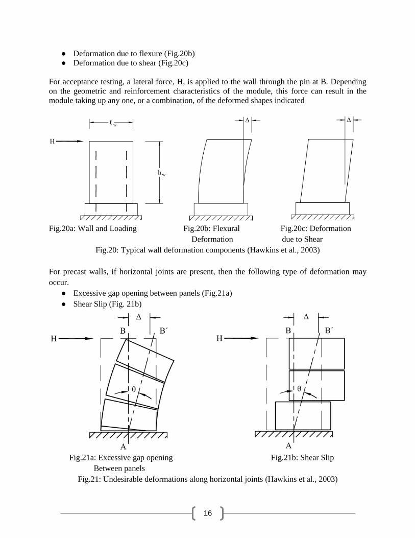
5. Horizontal load testing protocol on Precast Walls (Hawkins and Ghosh, 2003):
A lateral force is applied at the topmost point of the wall panel (Fig. 20a), and the horizontal
deflection of top point and the drift ratio are measure. This could cause the following type of
deformations.
16
● Deformation due to flexure (Fig.20b)
● Deformation due to shear (Fig.20c)
For acceptance testing, a lateral force, H, is applied to the wall through the pin at B. Depending
on the geometric and reinforcement characteristics of the module, this force can result in the
module taking up any one, or a combination, of the deformed shapes indicated
Fig.20a: Wall and Loading Fig.20b: Flexural Fig.20c: Deformation
Deformation due to Shear
Fig.20: Typical wall deformation components (Hawkins et al., 2003)
For precast walls, if horizontal joints are present, then the following type of deformation may
occur.
● Excessive gap opening between panels (Fig.21a)
● Shear Slip (Fig. 21b)
Fig.21a: Excessive gap opening Fig.21b: Shear Slip
Between panels
Fig.21: Undesirable deformations along horizontal joints (Hawkins et al., 2003)
17
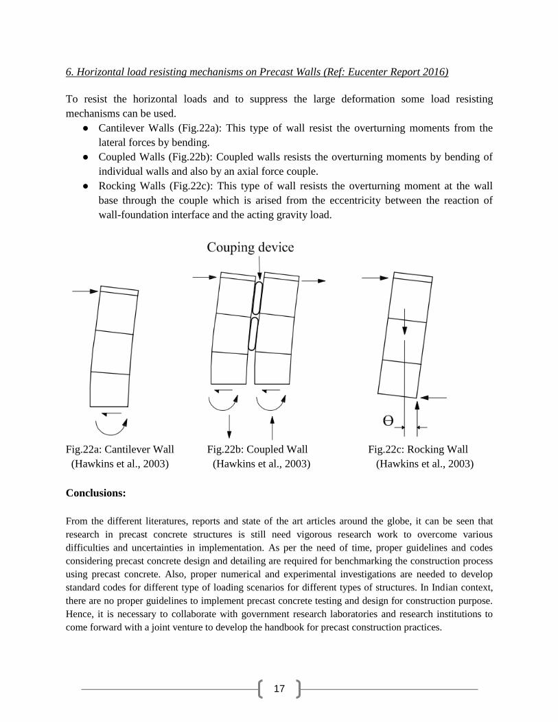
6. Horizontal load resisting mechanisms on Precast Walls (Ref: Eucenter Report 2016)
To resist the horizontal loads and to suppress the large deformation some load resisting
mechanisms can be used.
● Cantilever Walls (Fig.22a): This type of wall resist the overturning moments from the
lateral forces by bending.
● Coupled Walls (Fig.22b): Coupled walls resists the overturning moments by bending of
individual walls and also by an axial force couple.
● Rocking Walls (Fig.22c): This type of wall resists the overturning moment at the wall
base through the couple which is arised from the eccentricity between the reaction of
wall-foundation interface and the acting gravity load.
Fig.22a: Cantilever Wall Fig.22b: Coupled Wall Fig.22c: Rocking Wall
(Hawkins et al., 2003) (Hawkins et al., 2003) (Hawkins et al., 2003)
Conclusions:
From the different literatures, reports and state of the art articles around the globe, it can be seen that
research in precast concrete structures is still need vigorous research work to overcome various
difficulties and uncertainties in implementation. As per the need of time, proper guidelines and codes
considering precast concrete design and detailing are required for benchmarking the construction process
using precast concrete. Also, proper numerical and experimental investigations are needed to develop
standard codes for different type of loading scenarios for different types of structures. In Indian context,
there are no proper guidelines to implement precast concrete testing and design for construction purpose.
Hence, it is necessary to collaborate with government research laboratories and research institutions to
come forward with a joint venture to develop the handbook for precast construction practices.

18
References:
1. Northeast Precast company blogs- By Peter Gorgas (Precast.org)
2. “Numerical and experimental evaluation of the seismic response of precast wall
connections”, EUCENTER Report, 2016
3. Negro, Paolo, Dionysios A. Bournas, and Francisco J. Molina. "Pseudodynamic
tests on a full-scale 3-storey precast concrete building: global
response." Engineering Structures 57 (2013): 594-608.
4. Bournas, Dionysios A., Paolo Negro, and Francisco J. Molina. "Pseudodynamic
tests on a full-scale 3-storey precast concrete building: behavior of the mechanical
connections and floor diaphragms." Engineering Structures 57 (2013): 609-627.
5. Hawkins, N.M, Ghosh, S.K, “Acceptance Criteria for Special Precast Concrete
Structural Walls Based on Validation Testing”, NEHRP Provisions permits, 2003
6. Xue, W., & Yang, X. (2010). Seismic tests of precast concrete, moment-resisting
frames and connections. PCI journal, 55(3).
7. http://www.mapaprecast.org/