review of use cases and framework ii -...
TRANSCRIPT

SOCRATES D2.6
Page 1 (28)
INFSO-ICT-216284 SOCRATES
D2.6
Review of use cases and framework II
Contractual Date of Delivery to the CEC: 31.12.2009
Actual Date of Delivery to the CEC: 18.12.2009
Authors: Neil Scully, John Turk, Remco Litjens, Ulrich Türke, Mehdi Amirijoo,
Thomas Jansen, Lars Christoph Schmelz
Reviewers: Hans van den Berg, Andreas Eisenblätter
Participants: VOD, TNO, ATE, EAB, TUBS, NSN-D
Workpackage: WP2 – Use cases and framework for self-organisation
Estimated person months: 1.5
Security: PU
Nature: R
Version: 1.0
Total number of pages: 28
Abstract: The SOCRATES (Self-Optimisation and self-ConfiguRATion in wirelEss networkS) project
aims at the development of self-organisation methods for LTE radio networks. Self-organisation
comprises self-optimisation, self-configuration and self-healing. This document is an update of the use
cases and framework that were initially defined in SOCRATES deliverables D2.1, D2.2, D2.3, D2.4 and
D2.5, and is based on new insights and progress in the project.
Keyword list: Self-organisation, self-configuration, self-optimisation, self-healing, LTE, E-UTRA, radio
interface, use cases, requirements, framework, simulation, reference scenarios, architecture

SOCRATES D2.6
Page 2 (28)
Executive Summary
The SOCRATES (Self-Optimisation and self-ConfiguRATion in wirelEss networkS) project is
developing self-organisation methods for LTE radio networks. Self-organisation is expected to
substantially reduce the necessary human intervention in network operations with the effect of a
significant reduction in operational expenditure (OPEX) and an improvement in service quality. Self-
organisation comprises self-configuration, self-optimisation, and self-healing.
This document contains updates to the previous SOCRATES WP2 deliverables D2.1, D2.2, D2.3, D2.4
and D2.5. In the SOCRATES deliverable D2.1 [1] twenty-four use cases for self-organisation are
described. In D2.2 [2] the technical and business requirements put on solutions for self-organisation are
analysed in detail, and in D2.3 [3] criteria, methodologies and scenarios to assess the solutions for self-
organisation are described. In deliverable D2.4 [4] the framework for the development of self-organising
algorithms was defined. In deliverable D2.5 [5], various elements that contribute to the framework were
either added or updated, providing an extension to the work in the previous WP2 deliverables D2.1, D2.2,
D2.3 and D2.4.
This document reflects new insights from the progress in the overall project since the issue of D2.5, and
further defines the framework. There are three sections in this document. First, there is an updated section
on reference scenarios. This section defines the details of the basic macro scenario, and this scenario can
be used to realistically model a macro-cell network. There is also a new section on architectural issues. In
contrast to the high-level architecture sections in previous WP2 deliverables, this section considers the
architecture for individual use cases. Finally, there is a new section on integration of use cases, which
considers aspects such as objectives, approach, scenarios, assessment methods and architecture.
Specifically, it considers the architectural components required to integrate SON functionality, and the
simulation approach for modelling integrated SON functions.
This document complements previous WP2 deliverables (D2.1 to D2.5), and to gain a complete picture it
should be read in combination with those deliverables.
The work on development of solutions for self-optimisation (in WP3), and self-configuration and self-
healing (in WP4) has enabled a better definition of the use cases and framework in WP2. In return, the
updates in this document serve as a reference for further work in WP3 and WP4.
With this deliverable, the WP2 work in SOCRATES is completed. The work package has successfully
fulfilled its role of defining the use cases and framework for SOCRATES, and the WP2 results have
served as an effective basis for the work in WP3 and WP4.
SOCRATES D2.6
Page 3 (28)
Authors
Partner Name Phone / Fax / E-mail
VOD Neil Scully Phone: +44 1635 682380
Fax: +44 1635 676147
E-mail: [email protected]
John Turk Phone: +44 1635 676254
Fax: +44 1635 676147
E-mail: [email protected]
TNO Remco Litjens Phone : +31 6 5191 6092
Fax: +31 15 285 7375
E-mail: [email protected]
ATE Ulrich Türke Phone: +49 30 79745880
Fax: +49 30 79786843
E-mail: [email protected]
EAB Mehdi Amirijoo Phone: +46 10 7115290
Fax: +46 10 7114990
E-mail: [email protected]
TUBS Thomas Jansen Phone: +49 531 391 2486
Fax: +49 531 391 5192
E-mail: [email protected]
NSN-D Lars Christoph Schmelz Phone: +49 89 636-79585
Fax: +49 89 636-75147
E-mail: [email protected]
SOCRATES D2.6
Page 4 (28)
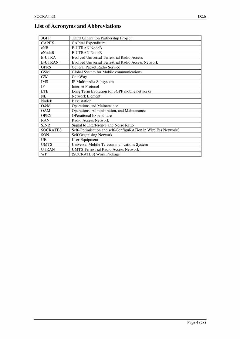
List of Acronyms and Abbreviations
3GPP Third Generation Partnership Project
CAPEX CAPital Expenditure
eNB E-UTRAN NodeB
eNodeB E-UTRAN NodeB
E-UTRA Evolved Universal Terrestrial Radio Access
E-UTRAN Evolved Universal Terrestrial Radio Access Network
GPRS General Packet Radio Service
GSM Global System for Mobile communications
GW GateWay
IMS IP Multimedia Subsystem
IP Internet Protocol
LTE Long Term Evolution (of 3GPP mobile networks)
NE Network Element
NodeB Base station
O&M Operations and Maintenance
OAM Operations, Administration, and Maintenance
OPEX OPerational Expenditure
RAN Radio Access Network
SINR Signal to Interference and Noise Ratio
SOCRATES Self-Optimisation and self-ConfiguRATion in WirelEss NetworkS
SON Self Organising Network
UE User Equipment
UMTS Universal Mobile Telecommunications System
UTRAN UMTS Terrestrial Radio Access Network
WP (SOCRATES) Work Package
SOCRATES D2.6
Page 5 (28)
Table of Contents
1 Introduction..................................................................................................6
2 Reference scenarios....................................................................................8
2.1 Introduction ................................................................................................................................. 8 2.2 Scenario Data .............................................................................................................................. 8
2.2.1 Network configuration ........................................................................................................ 8 2.2.2 Pathloss data ..................................................................................................................... 10 2.2.3 Clutter data........................................................................................................................ 10 2.2.4 Height data........................................................................................................................ 12 2.2.5 Traffic data........................................................................................................................ 12 2.2.6 Mobility data..................................................................................................................... 13
2.3 Data Formats ............................................................................................................................. 15
3 SON architecture – use case preferences...............................................17
4 Integration of SON algorithms..................................................................19
4.1 Introduction ............................................................................................................................... 19 4.2 Objectives.................................................................................................................................. 19
4.2.1 Resolve control parameter conflicts.................................................................................. 19 4.2.2 Resolve observability conflicts ......................................................................................... 20 4.2.3 Stability mechanisms ........................................................................................................ 20 4.2.4 SON performance measurement ....................................................................................... 20 4.2.5 3GPP requirements ........................................................................................................... 20
4.3 Approach ................................................................................................................................... 20 4.3.1 General.............................................................................................................................. 20 4.3.2 Simulation approach ......................................................................................................... 21 4.3.3 Operator policy ................................................................................................................. 22
4.4 Network scenarios to be considered in design and demonstration ............................................ 23 4.5 Assessment method and metrics................................................................................................ 23 4.6 Architecture............................................................................................................................... 24
4.6.1 Autognostics ..................................................................................................................... 26 4.6.2 Super Operator Policy....................................................................................................... 26 4.6.3 Guard function .................................................................................................................. 26 4.6.4 Arbitrator .......................................................................................................................... 26 4.6.5 SON/eNB interface ........................................................................................................... 26
5 Conclusions and recommendations........................................................27
6 References .................................................................................................28

SOCRATES D2.6
Page 6 (28)
1 Introduction
The SOCRATES project aims at the development of self-organisation methods to enhance the operations
of LTE radio networks, reduce OPEX and improve network performance. This is to be achieved by
integrating network planning, configuration and optimisation into a mostly automated process requiring
minimal manual intervention.
In the preceding work package 2 (WP2) deliverables we have considered use cases (deliverable D2.1[1]),
requirements (deliverable D2.2 [2]) as well as assessment criteria and reference scenarios (deliverable
D2.3 [3]) for self-organisation. More specifically, a set of use cases has been defined, forming the basis,
within the SOCRATES project, for a common and clear view on self-organising functionalities for LTE
radio networks. The use case descriptions themselves list functionalities to be made self-organising and
point out what solutions should achieve. The specified requirements are indispensible for successfully
achieving these objectives, i.e. for the development of practically useful self-organising methods and
algorithms. Assessment criteria are needed to evaluate and compare the self-organisation algorithms that
will be developed in the project. Finally, the reference scenarios will be used for the simulation of the
self-organisation algorithms.
In deliverable D2.4 [4] the framework for the development of self-organising algorithms was defined.
The framework provides the underlying structure that the remainder of the project will be based on. In
particular, it provides an underlying set of ideas, principles, rules, and boundary conditions for the
development of self-organisation methods and algorithms in Work Package 3 (“Self-optimisation”) and
Work Package 4 (“Self-configuration and self-healing”).
Note that in SOCRATES, the framework is defined as not only consisting of the architecture, but
consisting of various components that together form the framework. Specifically, the SOCRATES
framework for the development of self-organisation functionalities consists of:
• Technical and business requirements
• Assessment criteria and methodology
• Reference scenarios
• Architectures
• Functional parameter groups
• Dependencies between and interactions among use cases/functionalities
• Methodology for algorithm development
In deliverable D2.5 [5] (a first update of D2.1-D2.4), various elements that contribute to the framework
were either added or updated. D2.5 reflected new insights from the progress in WP3 and WP4, and
further defined the framework.
The objective of WP2 is to define the framework as basis and input to WP3 and WP4 for the development
of actual self-organisation methods. However, the detail in defining the solutions is addressed in WP3 and
WP4, and documented in deliverables from these work packages. For example, the further work on
assessment criteria and methodology will be reported in deliverables D3.1 [6], D4.1 [7] and D4.2 [8], as it
has been found that on a more detailed level the criteria and methodologies are use case specific.
Therefore, there are only limited updates regarding the framework in WP2 at this later stage in the
SOCRATES project.
Given the above, this document only addresses specific aspects that relate to the framework in WP2. The
following sections are included in this document:
• Reference scenarios (section 2): This is a replacement of the reference scenarios section in D2.5.
The details of the basic macro scenario have been fully defined. As required, other scenarios will
be developed in parallel with the work in WP3 and WP4.
• Use case architecture (section 3): This section considers the architecture for individual use cases.
It is an update based on insights gained from the work on the individual use cases in WP3/4.
• Integration of SON algorithms (section 4): This section considers the integration of SON use
cases, a topic that has been identified as crucially important by SOCRATES. Preliminary work
on this topic has been documented in section 3 of D2.4 and section 7 of D2.5. The topic will be
addressed in detail in WP3 and documented in deliverable D3.2. In the present document, we
focus on the concepts and principles, and also identify possible simulation approaches.

SOCRATES D2.6
Page 7 (28)
It is important to point out that this document forms a whole entity together with deliverables D2.1 to
D2.5. As a document on its own, it contains a number of sections that do not form a consistent whole, but
as individual sections they add to the overall framework.
Therefore, a reader requiring information on one of the specific topics in this document can read only the
relevant section. However, a reader who is looking for an overall view on the framework should read this
document together with other WP2 deliverables (D2.1 to D2.5).

SOCRATES D2.6
Page 8 (28)
2 Reference scenarios
2.1 Introduction
The SOCRATES reference scenarios are for simulations by most use cases under study in our project.
The scenarios provide very realistic information including network data, environment data and mobility
data. Thus they are used in use case simulations whenever realistic network and user behaviour is crucial
for the individual studies. In order to allow for detailed simulations in every SOCRATES use case, the
scenarios have to meet the requirements of all these use cases.
This section summarizes the current status in the development of the realistic SOCRATES reference
scenarios. The requirements on the scenarios definition change with the progress in the work on the
individual use cases. Hence, the development is steadily adapted to the needs of the individual use cases.
This section updates section 5 of D2.5 [5].
The work on reference scenarios is split into four activities to be processed consecutively (cf., Section 5.1
in [1]). This split was made to ensure that the basic scenarios are ready timely for the use case
simulations. The remaining additions are sorted by the importance for the project:
1. Basic macro scenario
2. Addition of Femto- and Pico-Cells
3. Addition of time aspect
4. Scenario add-ons
The work on the macro scenario has been completed. Compared with the original plans, there are two
significant changes. Firstly, it has been decided to provide the data in a CSV file format, as opposed by
the original intention to provide the scenarios in an XML format. While XML provides the possibility to
generate a very detailed descriptive representation of the scenario data, CSV data is considered to be
easier to handle and ready to be used by most project partners. In addition, it has been decided to focus on
one reference scenario in the project (an area including a large city). This is for the reason that this
scenario already provides a diverse environment, including hilly terrain, rural areas, and urban areas.
The second scenario (Berlin) would add no clear benefit to this, but come at the cost of considerable
additional project effort.
Femto- and Pico-Cells are considered by the Home-eNodeB use case only. All other use cases consider
pure macro-cellular scenarios for their developments. The extension of the reference scenario w.r.t.
femto- and pico-cells is thus not considered to be within WP2 and handled as part of the work on the use
case.
The remaining two activities (item 3 and 4 from the above list) are carried out in parallel with the work in
WP3 and WP4 as the need arises. The requirements are defined as the technical work on the use cases
further proceeds. Activity 3 (addition of time aspects, i.e. temporal changes of the network configuration
and traffic aspects) are of particular interest when integrating multiple algorithms and studying their
interactions.
In the following sections, details of the realistic scenario and the corresponding data formats are
presented. These sections update the corresponding sections of our earlier deliverable D2.5 section 5 and
give the final configuration of the reference scenarios including the data formats.
2.2 Scenario Data
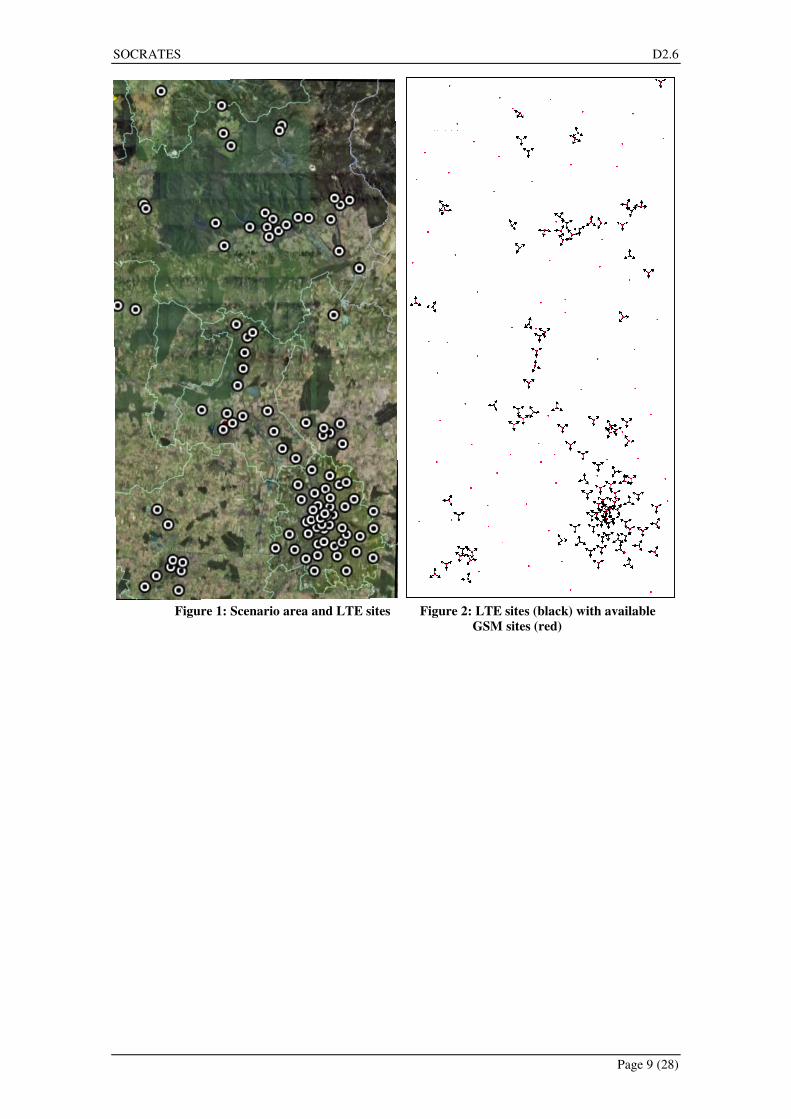
For a realistic reference scenario, an area of 72 km x 37 km has been chosen (cf., Figure 1). This area
includes a city and surrounding countryside, including hilly terrain. An LTE network has been generated
within the SOCRATES project based on the layout of operational 2G and 3G macro networks.
2.2.1 Network configuration
The data, provided by a network operator, is for 200 sites, of which 36 are UMTS only, 67 are UMTS and
GSM, 97 are GSM only.
For the LTE network considered within SOCRATES, the UMTS layout is used, with the same locations,
sector orientation, and antenna tilt. The resulting network comprising 103 sites and 309 cells is depicted
in Figure 2. The additional GSM sites are available as potential site candidates in case a use case requires
them.
SOCRATES D2.6
Page 9 (28)
Figure 1: Scenario area and LTE sites Figure 2: LTE sites (black) with available
GSM sites (red)
SOCRATES D2.6
Page 10 (28)
2.2.2 Pathloss data
For all antenna locations realistic pathloss prediction grids at the 2.6 GHz band are available. The
predictions employ two levels of resolution. For the 3km x 3km area centred at the base station, high
resolution prediction data with a pixel size of 10m is available. For the rest of the scenario the data is
available with 100m pixel size.
The predictions have been done using realistic antenna tilts. To enable SOCRATES to investigate the
effects of different antenna tilts in optimisation, further predictions have been made with 0°, 2°, 4°, and 6°
degree electrical tilt as well as 6° electrical plus 2° mechanical tilt for every cell. All predictions were
made using the same antenna type, instead of the various antenna types used in the real network.
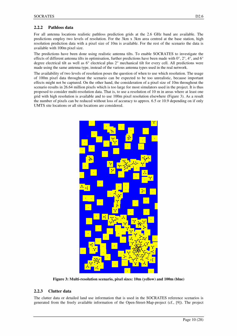
The availability of two levels of resolution poses the question of when to use which resolution. The usage
of 100m pixel data throughout the scenario can be expected to be too unrealistic, because important
effects might not be captured. On the other hand, the consideration of a pixel size of 10m throughout the
scenario results in 26.64 million pixels which is too large for most simulators used in the project. It is thus
proposed to consider multi-resolution data. That is, to use a resolution of 10 m in areas where at least one
grid with high resolution is available and to use 100m pixel resolution elsewhere (Figure 3). As a result
the number of pixels can be reduced without loss of accuracy to approx. 6.5 or 10.9 depending on if only
UMTS site locations or all site locations are considered.
Figure 3: Multi-resolution scenario, pixel sizes: 10m (yellow) and 100m (blue)
2.2.3 Clutter data
The clutter data or detailed land use information that is used in the SOCRATES reference scenarios is
generated from the freely available information of the Open-Street-Map-project (cf., [9]). The project

SOCRATES D2.6
Page 11 (28)
provides detailed vector data in XML format gathered by volunteers. The level of detail in the maps
depends on the region. The maps in dense urban areas generally include more information. In these areas,
the maps include street names and the locations of restaurants, hotels, street, pharmacies, etc. The
information that is needed to generate accurate land use maps is available throughout the considered area.
This means the XML-files from the Open-Street-Map-project qualify as data source to generate land use
maps for the SOCRATES reference scenarios.
The land use map shown in Figure 4 is generated using a MATLAB program to convert the data. The
resolution of the land use pixel map is 10 m. Five different land use classes are considered in the
SOCRATES reference scenarios: natural areas (green), buildings (brown), water (blue), streets (grey) and
railway tracks (black).
Figure 4: Clutter data generated from the maps provided by the Open-Street-Map project
(green: "natural", brown: "building", blue: "water", grey: "street", black: "railway track")
SOCRATES D2.6
Page 12 (28)
2.2.4 Height data
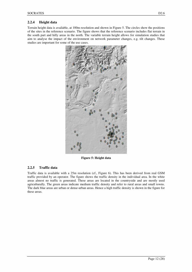
Terrain height data is available, at 100m resolution and shown in Figure 5. The circles show the positions
of the sites in the reference scenario. The figure shows that the reference scenario includes flat terrain in
the south part and hilly areas in the north. The variable terrain height allows for simulation studies that
aim to analyse the impact of the environment on network parameter changes, e.g. tilt changes. These
studies are important for some of the use cases.
Figure 5: Height data
2.2.5 Traffic data
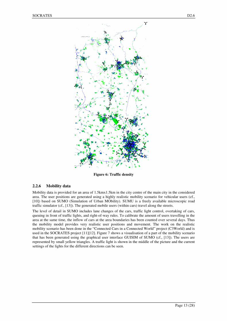
Traffic data is available with a 25m resolution (cf., Figure 6). This has been derived from real GSM
traffic provided by an operator. The figure shows the traffic density in the individual area. In the white
areas almost no traffic is generated. These areas are located in the countryside and are mostly used
agriculturally. The green areas indicate medium traffic density and refer to rural areas and small towns.
The dark blue areas are urban or dense-urban areas. Hence a high traffic density is shown in the figure for
these areas.
SOCRATES D2.6
Page 13 (28)
Figure 6: Traffic density
2.2.6 Mobility data
Mobility data is provided for an area of 1.5kmx1.5km in the city centre of the main city in the considered
area. The user positions are generated using a highly realistic mobility scenario for vehicular users (cf.,
[10]) based on SUMO (Simulation of Urban MObility). SUMU is a freely available microscopic road
traffic simulator (cf., [13]). The generated mobile users (within cars) travel along the streets.
The level of detail in SUMO includes lane changes of the cars, traffic light control, overtaking of cars,
queuing in front of traffic lights, and right-of-way rules. To calibrate the amount of users travelling in the
area at the same time, the inflow of cars at the area boundaries has been counted over several days. Thus
the mobility model provides very realistic user positions and movement. The work on the realistic
mobility scenario has been done in the “Connected Cars in a Connected World” project (C3World) and is
used in the SOCRATES project [11][12]. Figure 7 shows a visualisation of a part of the mobility scenario
that has been generated using the graphical user interface GUISIM of SUMO (cf., [13]). The users are
represented by small yellow triangles. A traffic light is shown in the middle of the picture and the current
settings of the lights for the different directions can be seen.

SOCRATES D2.6
Page 14 (28)
Figure 7: The mobility scenario in SUMO showing cars (yellow triangles) on streets
SOCRATES D2.6
Page 15 (28)
2.3 Data Formats
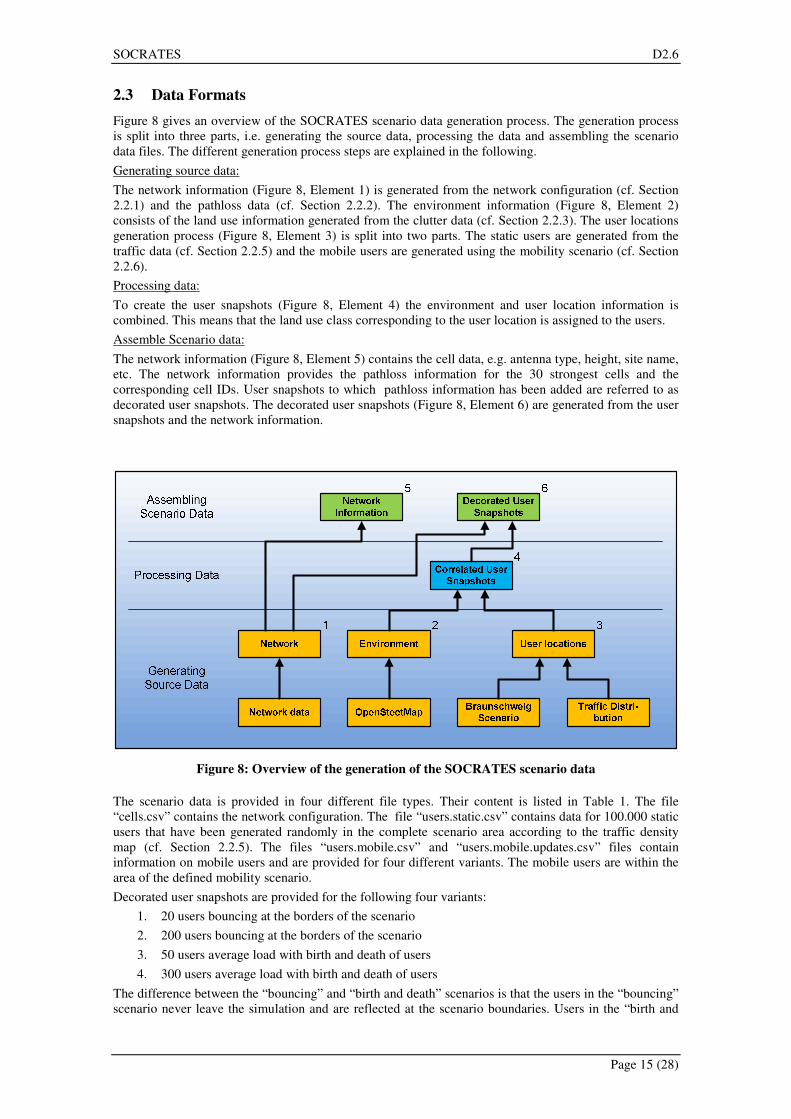
Figure 8 gives an overview of the SOCRATES scenario data generation process. The generation process
is split into three parts, i.e. generating the source data, processing the data and assembling the scenario
data files. The different generation process steps are explained in the following.
Generating source data:
The network information (Figure 8, Element 1) is generated from the network configuration (cf. Section
2.2.1) and the pathloss data (cf. Section 2.2.2). The environment information (Figure 8, Element 2)
consists of the land use information generated from the clutter data (cf. Section 2.2.3). The user locations
generation process (Figure 8, Element 3) is split into two parts. The static users are generated from the
traffic data (cf. Section 2.2.5) and the mobile users are generated using the mobility scenario (cf. Section
2.2.6).
Processing data:
To create the user snapshots (Figure 8, Element 4) the environment and user location information is
combined. This means that the land use class corresponding to the user location is assigned to the users.
Assemble Scenario data:
The network information (Figure 8, Element 5) contains the cell data, e.g. antenna type, height, site name,
etc. The network information provides the pathloss information for the 30 strongest cells and the
corresponding cell IDs. User snapshots to which pathloss information has been added are referred to as
decorated user snapshots. The decorated user snapshots (Figure 8, Element 6) are generated from the user
snapshots and the network information.
Figure 8: Overview of the generation of the SOCRATES scenario data
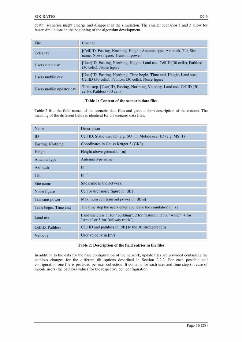
The scenario data is provided in four different file types. Their content is listed in Table 1. The file
“cells.csv” contains the network configuration. The file “users.static.csv” contains data for 100.000 static
users that have been generated randomly in the complete scenario area according to the traffic density
map (cf. Section 2.2.5). The files “users.mobile.csv” and “users.mobile.updates.csv” files contain
information on mobile users and are provided for four different variants. The mobile users are within the
area of the defined mobility scenario.
Decorated user snapshots are provided for the following four variants:
1. 20 users bouncing at the borders of the scenario
2. 200 users bouncing at the borders of the scenario
3. 50 users average load with birth and death of users
4. 300 users average load with birth and death of users
The difference between the “bouncing” and “birth and death” scenarios is that the users in the “bouncing”
scenario never leave the simulation and are reflected at the scenario boundaries. Users in the “birth and
SOCRATES D2.6
Page 16 (28)
death” scenarios might emerge and disappear in the simulation. The smaller scenarios 1 and 3 allow for
faster simulations in the beginning of the algorithm development.
File Content
Cells.csv [Cell]ID, Easting, Northing, Height, Antenna type, Azimuth, Tilt, Site
name, Noise figure, Transmit power
Users.static.csv [User]ID, Easting, Northing, Height, Land use, CellID (30 cells), Pathloss
(30 cells), Noise figure
Users.mobile.csv [User]ID, Easting, Northing, Time begin, Time end, Height, Land use,
CellID (30 cells), Pathloss (30 cells), Noise figure
Users.mobile.updates.csv Time step, [User]ID, Easting, Northing, Velocity, Land use, CellID (30
cells), Pathloss (30 cells)
Table 1: Content of the scenario data files
Table 2 lists the field names of the scenario data files and gives a short description of the content. The
meaning of the different fields is identical for all scenario data files.
Name Description
ID Cell ID, Static user ID (e.g. SU_1), Mobile user ID (e.g. MS_1)
Easting, Northing Coordinates in Gauss Krüger 3 (GK3)
Height Height above ground in [m]
Antenna type Antenna type name
Azimuth In [°]
Tilt In [°]
Site name Site name in the network
Noise figure Cell or user noise figure in [dB]
Transmit power Maximum cell transmit power in [dBm]
Time begin, Time end The time step the users enter and leave the simulation in [s]
Land use Land use class (1 for "building", 2 for "natural", 3 for "water", 4 for
"street" or 5 for "railway track")
CellID, Pathloss Cell ID and pathloss in [dB] to the 30 strongest cells
Velocity User velocity in [m/s]
Table 2: Description of the field entries in the files
In addition to the data for the base configuration of the network, update files are provided containing the
pathloss changes for the different tilt options described in Section 2.2.2. For each possible cell
configuration one file is provided per user collection. It contains for each user and time step (in case of
mobile users) the pathloss values for the respective cell configuration.
SOCRATES D2.6
Page 17 (28)
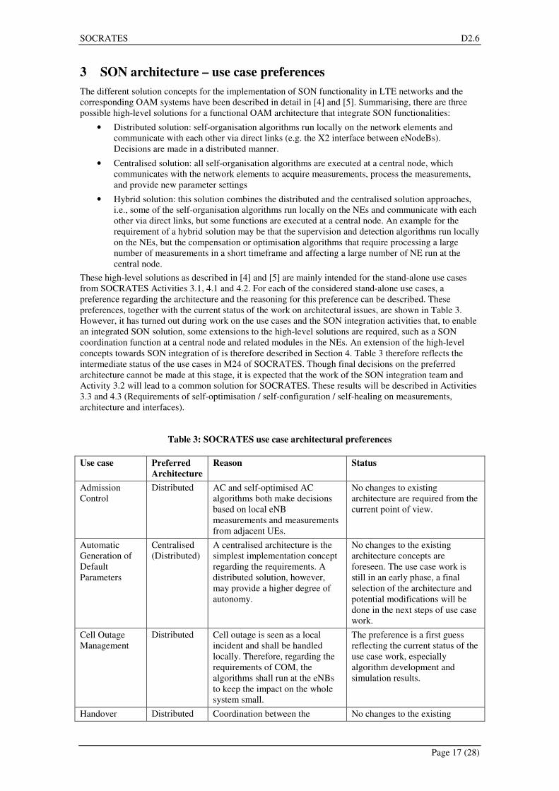
3 SON architecture – use case preferences
The different solution concepts for the implementation of SON functionality in LTE networks and the
corresponding OAM systems have been described in detail in [4] and [5]. Summarising, there are three
possible high-level solutions for a functional OAM architecture that integrate SON functionalities:
• Distributed solution: self-organisation algorithms run locally on the network elements and
communicate with each other via direct links (e.g. the X2 interface between eNodeBs).
Decisions are made in a distributed manner.
• Centralised solution: all self-organisation algorithms are executed at a central node, which
communicates with the network elements to acquire measurements, process the measurements,
and provide new parameter settings
• Hybrid solution: this solution combines the distributed and the centralised solution approaches,
i.e., some of the self-organisation algorithms run locally on the NEs and communicate with each
other via direct links, but some functions are executed at a central node. An example for the
requirement of a hybrid solution may be that the supervision and detection algorithms run locally
on the NEs, but the compensation or optimisation algorithms that require processing a large
number of measurements in a short timeframe and affecting a large number of NE run at the
central node.
These high-level solutions as described in [4] and [5] are mainly intended for the stand-alone use cases
from SOCRATES Activities 3.1, 4.1 and 4.2. For each of the considered stand-alone use cases, a
preference regarding the architecture and the reasoning for this preference can be described. These
preferences, together with the current status of the work on architectural issues, are shown in Table 3.
However, it has turned out during work on the use cases and the SON integration activities that, to enable
an integrated SON solution, some extensions to the high-level solutions are required, such as a SON
coordination function at a central node and related modules in the NEs. An extension of the high-level
concepts towards SON integration of is therefore described in Section 4. Table 3 therefore reflects the
intermediate status of the use cases in M24 of SOCRATES. Though final decisions on the preferred
architecture cannot be made at this stage, it is expected that the work of the SON integration team and
Activity 3.2 will lead to a common solution for SOCRATES. These results will be described in Activities
3.3 and 4.3 (Requirements of self-optimisation / self-configuration / self-healing on measurements,
architecture and interfaces).
Table 3: SOCRATES use case architectural preferences
Use case Preferred
Architecture
Reason Status
Admission
Control
Distributed AC and self-optimised AC
algorithms both make decisions
based on local eNB
measurements and measurements
from adjacent UEs.
No changes to existing
architecture are required from the
current point of view.
Automatic
Generation of
Default
Parameters
Centralised
(Distributed)
A centralised architecture is the
simplest implementation concept
regarding the requirements. A
distributed solution, however,
may provide a higher degree of
autonomy.
No changes to the existing
architecture concepts are
foreseen. The use case work is
still in an early phase, a final
selection of the architecture and
potential modifications will be
done in the next steps of use case
work.
Cell Outage
Management
Distributed Cell outage is seen as a local
incident and shall be handled
locally. Therefore, regarding the
requirements of COM, the
algorithms shall run at the eNBs
to keep the impact on the whole
system small.
The preference is a first guess
reflecting the current status of the
use case work, especially
algorithm development and
simulation results.
Handover Distributed Coordination between the No changes to the existing

SOCRATES D2.6
Page 18 (28)
optimisation adjacent cells is done via an X2
interface information exchange
architecture concepts are
necessary, but some additional
message exchanges over the X2
interface may be required.
Home eNodeB Distributed Due to the potentially huge
number of Home eNodeBs,
centralised control is impractical.
No architectural issues have yet
been handled for this use case.
Interference
Coordination
Centralised It is not clear what gains inter-cell
interference coordination can
realise in the ideal case of full
information and global control,
let alone from local information
and distributed control. The
former should therefore serve as a
reference point with which to
compare later attempts.
Initial investigation (algorithm
development and simulations) is
made with a centralised
architecture, but investigations
will be enhanced towards a
distributed solution at a later
stage in the use case work.
Load Balancing Hybrid A distributed architecture is
required for direct LB actions as
the Source eNBs needs to get
information about the load
currently hosted by the Target
eNB and available "space", and
decide the amount of load/users
to be forced to HO to neighbour
cell. This communication will
take place between neighbouring
cells over the X2 interface.
A centralised architecture is
required to indicate the direction
of load shifting, e.g., by sending a
prioritised list of Target eNBs
from OAM to eNBs which
participate in LB. This is part of
SON and not required but
desirable.
No changes to existing
architecture are required from
current point of view.
Packet
Scheduling
Distributed Packet scheduling as a local
(intra-cell) scope. Therefore a
distributed algorithm is preferred
to keep the impact on the system
small.
There is currently no necessity
seen for a self-optimised packet
scheduling solution – however, if
a solution will be implemented, a
distributed architecture seems
most appropriate.

SOCRATES D2.6
Page 19 (28)
4 Integration of SON algorithms
4.1 Introduction
D2.4 section 5 states that to develop integration techniques “…we first need more insight and experience
on the actual development of methods for self-optimisation and self-configuration/healing, which we
expect to obtain in WP3 and WP4…” As WP3 and WP4 are now mature, we are in a position to do this
development of integration techniques. It is also apparent that the integration content of D2.5 is now of
limited relevance.
So far in the SOCRATES project, SON functions have been developed independently. We now need to
find a way to integrate them so they work together. Individually, the SON functions optimise a narrow
field. Integration will coordinate these to optimise network performance in a coherent manner. It is
necessary to address problems such as resolving conflicts between SON functions over parameters, and
where SON functions use the same measurables.
This chapter introduces the objectives, 1.2, and the approach, 1.3 of the D3.2 SON integration activity. It
describes the scenarios, 1.4, which need to considered, and how SON integration performance can be
assessed and measured, 1.5. Finally, an example architecture for an integrated SON solution is presented,
including a description of key functions.
4.2 Objectives
This section describes the objectives of the activity.
4.2.1 Resolve control parameter conflicts
There are examples of more than one SON function using the same parameter for optimisation, which can
lead to the SON functions having conflicting requirements for the parameter setting, as is shown in Figure
9. Two examples are:
• SON function A wants parameter P3 to increase while SON function B wants a decrease.
• SON function A wants a large increase for parameter P3, while SON function B wants to
cautiously allow only gradual increments while monitoring the effects.
We refer to this type of conflict as a control parameter conflict. If not addressed, these conflicts will
results in system instability, poor performance, etc.
Figure 9: SON functions A and B both want to control parameter P3 to optimise metric A and
metric B respectively
Therefore, the integration part of the SOCRATES project needs to develop techniques to combine the
SON function desires in a manner to satisfy all.
An example of control parameter conflict is handover optimisation and load balancing, which both
operate on HO hysteresis, time to trigger and HO offset.
P1
P2
P3
P4
P5
P6
P7
SON function A
SON function B
Metric B
Metric A SON function A uses
parameters P1 to P3
to optimise Metric A
SON function B uses
parameters P3 to P7
to optimise Metric B

SOCRATES D2.6
Page 20 (28)
4.2.2 Resolve observability conflicts
Consider SON function C which changes parameters to optimise metric C, and SON function D which
uses different parameters to also optimise metric C. See Figure 10.
Figure 10: SON functions C and D both want to optimise metric C
This can lead to problems such as a SON function’s actions resulting in a different SON function taking
action, and so on, causing a ripple of activity in an unwanted manner. Another problem could be that
SON functions A and B reach extreme parameter values as one tries to increase measurement D and the
other tries to maintain a constant value for metric C.
It is necessary to ensure this type of interaction is understood and to develop appropriate strategies. Note,
to what degree observability conflicts actually cause problems is not yet known and needs to be further
evaluated.
An example of this is the integration of the interference coordination function and the packet scheduling
optimisation function, both of which aim at optimising cell throughput while providing some minimum
degree of fairness
4.2.3 Stability mechanisms
Within a complex, self-controlled system it is possible to have unexpected and undesirable effects, such
as one or more control parameters reaching maximum value, a control parameter oscillating, or a
measurable oscillating. It is important to understand these issues and to provide techniques that detect and
react to incipient or actual instabilities.
4.2.4 SON performance measurement
In order to assess the performance of integration techniques, it is necessary to be able to measure both the
performance of the network, e.g. coverage and quality, and the activity of the integration function, e.g. a
measure of how often is it necessary to resolve parameter conflicts.. This will require new metrics to be
developed.
4.2.5 3GPP requirements
It is also an objective of the integration activity to identify new requirements for 3GPP, for example what
data needs to be passed between network elements.
4.3 Approach
This section describes the approach which will be taken to achieve the objectives previously described.
4.3.1 General
The integration activity of the SOCRATES project will use the SON functions already developed, and
integrate one or more of them in a simulator, This exercise will demonstrate the benefit of SON
integration, and the lessons learned from this exercise will aid development of the general case. In parallel
to the simulator work, non-specific SON integration techniques will be developed, such that potential
future updates to the SON features, and not-yet-thought-of SON functions can be accommodated. This
approach suggests a modular solution with defined interactions between modules, as opposed to a single,
complex SON function.
SON function C
SON function D
Metric C
Metric D
P8
P9
P10
P11
P12
P13
SOCRATES D2.6
Page 21 (28)
Two paths will be followed:
- The use of pragmatic, simple techniques using all or some of the SON algorithms already
delivered in SOCRATES. The emphasis is to demonstrate two or more SON functions
working together successfully.
- The use of more complex methods, with generalised integration and evaluation techniques,
including advanced methods for improving stability and resolving conflicts. This will
involve development of concepts, some of which can be demonstrated in the SOCRATES
project.
4.3.2 Simulation approach
In the stand-alone development of SON solutions for the different SON functions, dedicated simulation
tools have been developed. Examples are a simulator for handover and a different simulator for admission
control. These tools are characterised by modelling choices that are specific for the use case purposes. In
the integration phase, where multiple SON functions are brought together and jointly studied, there is an
obvious need to also integrate the simulation tools.
We distinguish four approaches to integrating the different simulation tools. These approaches are briefly
discussed below, in decreasing order of an expected degree of evaluation accuracy:
1. Develop the ‘mother of all simulators’
In this approach a single simulation tool would be developed that could be applied to evaluate
any combination of SON functions. Such a simulator should then cover all modelling aspects,
allow consideration of all scenarios and include all SON functions.
Key advantage of this approach is that in principle it allows the best possible quantitative
evaluation of combined SON functions and different coordination functions. Key drawbacks are
that (i) this approach most likely requires a tremendous programming effort from a single person
(or potentially a small, closely cooperating group and hence is likely to lead to significant
delays; (ii) the complexity of the developed simulator is likely to imply very long simulation
times; this is mostly due to the fact that the appropriate assessment of some SON functions (e.g.
self-optimisation of admission control parameters) may require simulation of several hours,
whereas the assessment of other SON functions (e.g. the optimisation of packet scheduling
parameters) require that these simulations are done with a TTI (1 ms) resolution.
2. Develop an integrated simulator for specific groups of SON functions
Certain groups of SON functions can be identified as interesting for study of their integration.
The SON function grouping can be made on the basis of SON functions that are related in the
affected control parameters, the used measurements and/or their performance objectives. For
each of these groups, one of the existing simulators is selected for further enhancement to be
able to evaluate the SON functions and all relevant scenarios for the combination of the covered
use cases.
Key advantage of this approach is that it allows a reliable quantitative evaluation of each
individual SON function group and the different coordination functions that are developed for
this SON function group. Key drawbacks are that (i) this approach still requires a significant
programming effort from (most likely) a single person per SON function group, although
certainly much less than for approach #1; (ii) the developed simulators do not allow the
development and evaluation of coordination functions for the set of all SON functions (note that
some degree of mutual influence exists between all SON functions, i.e. including those that are
included in different SON function groups.
3. Connect the existing use case-specific simulators via an exchange of control parameter
adaptations
In this approach, the use case-specific simulators are used in a stand-alone fashion. The control
parameter changes effectuated in the simulations of SON function A, are also (separately)
evaluated in the simulations of use case B, along with the associated scenario aspects that lead
SON function A to make the mentioned control parameter adjustment. Consider the following
example. The inter-cell interference coordination function may decide that in a certain time
period the circumstances (in terms of e.g. traffic mix or spatial user distribution) require an
adjustment of the transmit power distribution over the downlink physical resource blocks. Then
a separate simulation of the packet scheduler may be run with the adjusted transmit power

SOCRATES D2.6
Page 22 (28)
distribution and considering the same circumstances, in order to assess how the packet scheduler
and the associated SON function respond to these changes.
Key advantage of this approach is that, although there is still a need to align simulation models
to some extent, the required programming effort is limited and distributed over more people.
Key drawback is the potentially reduced accuracy of the performance evaluations. Ignoring real-
time interactions that do in reality exist is effectively an approximation of actual network
operations and hence will lead to an approximation of the actual network performance. Even if
this is intuitively clear as a qualitative statement, its quantitative significance, i.e. the actual
accuracy reduction can only truly be determined by comparing the obtained results with those
obtained with an evaluation tool as mentioned under approach #1 or #2 (see above).
This approach is expected to work best, i.e. lead to potentially bearable reduction of evaluation
accuracy, if there is a clear time scale separation between the operations of the different SON
functions and (potentially) underlying radio resource management schemes. If these time scales
are very similar, the degree of interaction between the different SON functions in a realistic
network may be much more significant than can be adequately captured when following this
approach.
It is noted that even if a clear time scale separation exists, the SON functions may still be so
strongly connected that their separate assessment would lead to unreliable performance results.
A good example of this is the relation between inner- and outer-loop power control in e.g.
UMTS networks, which operate on distinct timescales (1500 Hz vs. 25-100 Hz) yet the control
steps are so strongly connected that separate evaluation has limited sense.
Hence it depends on the specific combination of SON functions whether this integration
approach has any merit, which should therefore be considered on a case-by-case basis.
4. Connect the developed use case-specific simulators via an exchange of the impact that control
parameter adaptations have on the relevant measurables
This approach is similar to approach #3, only in this case not the control parameter changes
effectuated by one SON function in the associated simulator are ‘carried over to’ another
simulator (evaluating another SON function), but rather the impact of the control parameter
changes on the relevant measurables are ‘carried over’. As an illustrative example, if one SON
function decides to adjust antenna down tilts, the effect of this on another SON function (whose
associated simulator may not explicitly model and/or adjust down tilts) may be modelled by
adjusted SINR characteristics.
The (dis)advantages of this approach are similar to those mentioned under approach #3.
Compared to approach #3, however, this approach may require more effort, since the effects of
control parameter changes in simulator A on the measurables as used in simulator B need to be
modelled. It is further noted that this approach may (also) not be suitable to each combination of
use cases. Particularly in a case were the control parameters of simulator A are in fact present in
simulator B, in which it would give strange effects to bypass adjusting those control parameters
and only affect the measurables.
While the above discussion is rather general in nature, the concrete choice of approach will depend on the
specific grouping of the SON functions. The choice will be based on the specifics of the combined SON
functions, control parameters and key measurables, a possible difference in operational time scales of the
integrated SON functions, the suitability of the available simulation tools for consideration of integrated
SON functions, and the availability of personal effort.
4.3.3 Operator policy
An operator policy function is needed as an interface between the operator’s desires and the decisions
made by SON functions.
It may be helpful to have operator policies for each SON function individually, with a ‘super-operator’
policy operating at a higher level within a SON coordination function. This super operator policy can, for
example, consist of “elements” and “composition.” Elements capture the basic elements of network
performance, such as coverage, quality and capacity, while composition captures the relationship between
these elements. The composition will mostly be not as simple as “quality is more important the
coverage,” but can have multi-dimensional operating zones where the desired balance between the
elements is defined.

SOCRATES D2.6
Page 23 (28)
Figure 11: Example of an operating zone
Figure 11 illustrates the concept of a two-dimensional operating zone for quality and coverage. As long as
coverage and quality satisfy their minimum levels (performance is within the satisfactory area) then the
performance is acceptable. It can also be used to convey to a SON function that if quality reaches a
certain minimum threshold, then coverage should be reduced to maintain that minimum quality. In a real
situation, the operating zone would have a much more complex shape and be multi-dimensional.
4.4 Network scenarios to be considered in design and demonstration
There are two general types of scenario to be considered in the design and demonstration of the
integration function:
1) Stable conditions. No large changes to the network environment, such as introduction of a new
cell, a cell failure, or large changes in offered user traffic are made. A demonstration could
include deliberately setting inappropriate parameter values, and observing the SON actions to
acquire optimised parameter values, and the corresponding network performance improvement.
2) Step changes. The network is subject to large changes such as introduction of a new cell, a cell
failure, or large changes in offered user traffic. It is then possible to observe SON actions to
adapt to these changes.
4.5 Assessment method and metrics
The integration of several use cases effectively comprises the integration of the SON functions that have
been developed to support these use cases, with an added coordination function that handles possibly
conflicting actions requested/proposed by the individual SON functions. When jointly considering several
use cases (in the above-mentioned sense), it is important to consider what is the most appropriate
assessment method for such an integrated case, considering e.g. (i) whether new assessment metrics may
be required, e.g. specifically related to the integration; (ii) define a single overall operator policy with an
appropriate translation to SON function-specific performance objectives as well as to suitable actions of
the coordinating function; and (iii) determine the overall assessment method to evaluate the achieved
performance for the integrated case, for different coordination methods. In the following, we elaborate on
these three aspects.
With regard to assessment metrics, we first note that upon integration of SON functionalities the relevant
assessment metrics, e.g. related to coverage, quality, accessibility, are typically inherited from the stand-
alone use case work. This effectively leads to a union of all assessment metrics that are considered in the
integrated case, with a noted need for alignment of the metric definitions. The assessment metrics need
alignment and possibly also other metrics that are used as input to SON functions. Regarding the time
scale at which assessment metrics are observed, it is stressed that this should not only be done at a global
level, but also zoomed in at brief periods of time when significant changes in e.g. traffic load, service
mix, mobility characteristics or network topology occur, i.e. those changes that trigger SON functions to
act.
Besides these inherited, united and aligned use case-specific assessment metrics, it is also important to
consider a number of metrics that indicate the importance, effectiveness and general behaviour of the
coordination function. For instance, when integrating SON functions that request conflicting control
parameter changes, it is informative to administer the frequency, type (same vs. opposite direction) and
Quality
Coverage
Minimum level
SOCRATES D2.6
Page 24 (28)
significance (relative magnitude) of conflicts, all indicators of (in)stability. This reflects to what extent
SON functions actually disagree and hence indicates the importance of having a good coordination
function. Furthermore, it is informative to monitor to what extent a given SON function and its
associated/delegated performance objectives suffer from seeing its control parameter change requests
overruled by the coordinator.
Consider a possible/typical coordination function which logs (conflicts of) control parameter change
requests, whose significance exceed some operator-specified threshold, for non-automated assessment by
a network optimisation expert. Such a threshold may be relatively low at the initial deployment of SON
solutions, and be increased over time as the confidence in the SON solutions increases. In this light it is
very informative to monitor the degree to which the human optimisation expert would need to be
consulted as a function of the logging threshold, as an indication of the induced OPEX.
Another possible implementation of a coordination function is to apply self-learning techniques in order
to adapt its conflict handling rules based on the observed impact of enforced decisions in achieving the
operator policy. Relevant performance metrics relate to the speed of learning, i.e. how fast does the
coordinator learn to relate cause and effect.
The operator policy typically combines several assessment metrics into one of different possible forms
(e.g. optimise metric A while placing constraints on metrics B and C, or optimising some weighted
average of metrics A, B, and C). As a consequence of the distributed work on stand-alone use cases so
far, the applied operator policies is likely to be not be uniformly defined. At least for each integrated case
of multiple use cases, but possibly even better at a global level, a single operator policy should be chosen
and appropriately translated to both the operations of the individual SON functions and the conflict
handling scheme is implemented by the coordination function. Understanding each individual SON
function’s role in achieving the overall operator policy may help in developing the best conflict handling
scheme.
The proposed overall assessment method for the evaluation of integrated SON functionalities under the
supervision of different coordination functions is outlined below. For a given integrated model and a
given scenario:
1. Evaluate scenario without SON solutions
2. Evaluate scenario with SON1, SON2, … considered in isolation
3. Evaluate scenario with SON1, SON2, … considered in parallel, but w.o. coordination
4. Evaluate scenario with SON1, SON2, … considered in parallel, and with different coordination
strategies
The objective is to compare these different cases in order to assess the gains from self-optimisation and
from coordination.
4.6 Architecture
There are various possible integration architecture models, of which one is shown in Figure 12. Note
Figure 12 is an example implementation of SON coordination, and not necessarily the design to be used
in SOCRATES However, the principles are likely to be common.
In Figure 12, it is assumed that some SON functions are in the eNBs and other SON functions are in a
central entity. Each SON function interfaces with a coordinator, either in the eNB or centrally, as
appropriate. This architecture facilitates SON functions to be developed independently, relying on the
coordinator to resolve inter-SON-function issues. The coordinator consists of a number of modules:
• Autognostics
• Super-operator policy
• Guard function
• Arbitrator
• SON/eNB interface
These modules will be described in some more detail below.

SOCRATES D2.6
Page 25 (28)
Figure 12. An example of SON coordination architecture and modules
Received measurement reports
Central Node
eNodeB SON entity Use Case 1
Algorith m
Use Case 2 Algorith m
Use Case N Algorith m ...
SON Coordination
eNodeB SON entity Use Case 1
Algorith m Use Case 2
Algorith m Use Case N
Algorith m ...
SON Coordination
eNodeB SON entity Use Case 1
Algorith m Use Case 2
Algorith m Use Case N
Algorith m ...
SON Coordination
eNodeB SON entity
SON func 1
Algorithm
SON func 2
Algorithm
SON func N
Algorithm
...
Central SON entity SON func 1
Algorithm SON func 2
Algorithm SON func N
Algorithm ...
eNodeB SON entity Use Case 1
Algorith m Use Case 2
Algorith m Use Case N
Algorith m ...
SON Coordination
eNodeB SON entity Use Case 1
Algorith m Use Case 2
Algorith m Use Case N
Algorith m ...
SON Coordination
eNodeB
SON Coordination
Super Operator policy
Autognostics
Guard function
SON coordination
Autognostics
Super operator policy
Guard function
Arbitrator
SON/eNB interface
SOCRATES D2.6
Page 26 (28)
4.6.1 Autognostics
The role of this module is to enable the SON entity to understand the system’s current state, by acquiring
and treating data, for example cell drop call rate, cell edge throughput and current cell DL tx power. It can
then be distributed to the SON functions. There will be advantages to doing certain actions once per cell
instead once per SON function. For example, it might be more efficient for each SON function to
interrogate SON autognostics module instead of each SON function interrogating the eNB’s statistics
function. Where data is treated, e.g., calculating the 95th percentile user throughput, it might be more
efficient to perform the calculation once in the autognostics module, instead of each of several SON
functions, as well as ensuring that each SON function is making decisions on a common set of data.
Another function of this module is to detect unreliable data, for example, if data from a neighbour cell
suddenly becomes all zeros, the autognostics function can decide if this is due to an outage, preventing
SON algorithms from trying to fix the problem with parameter changes. Autognostics can filter data, for
example, a quiet cell may only have one handover during a measurement period. If that one handover
results in a dropped call, then it would be possible for SON functions to make drastic over-reactions to the
100% failure rate.
4.6.2 Super Operator Policy
Each SON function will have its own operator policy, but there is a need for a super operator policy, as
discussed in section 4.3.3 within the coordinator.
4.6.3 Guard function
The role of the guard function is not directly optimisation, but to monitor the actions of the SON
functions and output from autognostics for extreme behaviour, sanity checks or incipient instability, and
to take appropriate rectifying action. An example of extreme behaviour is a parameter set to its maximum
value, and an example of unstable behaviour is an oscillating performance counter. Rectifying action
could be to reduce the step size of parameter changes, reduce the rate of parameter changes, or in an
extreme example, stop all changes and revert to a previously known good set of values.
4.6.4 Arbitrator
The arbitrator function takes action when there is conflict between SON functions. It must consider such
things as operator policy and urgency to make decisions, and consider changes over a period of time, for
example, function A may wish to increase a parameter value and 15 seconds later SON function B may
wish to decrease the same parameter. The arbitrator function is located in the eNB SON entity (not in the
central SON entity) because this function must be as close as possible to where parameter changes are
implemented, i.e. in the eNB. Changes proposed by the central SON are, nevertheless, still assessed by
the eNB arbitrator.
4.6.5 SON/eNB interface
When a decision has been made by the SON entity to make parameter changes, it is the role of the
SON/eNB interface to pass these change requests out into the part of the eNB that executes changes. The
SON/eNB interface module can also inform O&M that a SON-triggered parameter change has occurred.
If the SON entity needs to know current parameter values, the SON/eNB interface can fetch these values.
This module does not appear in the central SON entity. It may also log changes against triggers to allow
SON performance analysis.
SOCRATES D2.6
Page 27 (28)
5 Conclusions and recommendations
This section draws the conclusions from this document. As it is the final deliverable of WP2, some
general conclusions from the WP2 work are also included.
Properly defining use cases is an important first step before starting work on SON. SOCRATES identified
and described a total of 25 use cases, most of which relate to the radio interface.
To be able to assess the gains from developed SON solutions, it is important to define assessment criteria.
For assessment criteria to be effective, the following should be considered:
• Assessment of algorithms is traditionally based on metric types such as performance, coverage
and capacity. Assessment of SON requires the definition of some new metric types, specifically
OPEX, CAPEX and algorithm metrics (such as convergence and stability).
• As there are many individual metrics, benchmarking is required to obtain an overall assessment.
Benchmarking involves combining multiple metrics into a single overall metric.
• It is not possible to define a specific set of metrics that are the most important metrics for all use
cases. The most relevant metrics depend on the use case, as different use cases have different
aims.
• Assessing absolute gains achieved using SON is difficult. One reason for this is that the absolute
gains depend on the current operator approach.
• Overall, the assessment of gains is an important part of the development of SON algorithms, as
such an assessment is required to be able to direct the development of an algorithm.
The definition of realistic reference scenarios is important for the development of SON algorithms. If
unrealistic simplified scenarios are used, some effects that occur in real networks may be missed. For
example, load balancing will only achieve a gain if traffic is unevenly distributed.
The integration of SON use cases is an extremely important aspect of the development of SON. Many
interactions between use cases have been identified, and concepts have been defined to deal with these.
• Analysis has revealed that there are strong interdependencies among most of the use cases
related to the fact that parameters and measurables will be affected by multiple use cases. In
consequence, there is a strong urge for coordinating the functionalities supporting the use cases
in general and their control steps in particular. Based on our current understanding, this is
probably the biggest challenge to be mastered before SON will reliably contribute to network
performance and ease operations in practice.
• To be able to understand how to integrate use cases, it is necessary to first gain a thorough
insight into the individual use cases. It is necessary to understand what parameters are used by
each use cases, to see how they interact with other use cases. This can only be identified after the
development of solutions for individual use cases.
The preferred architecture for individual use cases varies per use case. Some use cases will be distributed,
some will be centralised, while some individual use case may be hybrid. It is clear that for the overall
architecture a hybrid solution is required.
Based on the results obtained in WP2, the following is recommended:
• SON development work should be driven by the gains that can be achieved. It should be clear
what the intended type of gain is, and the gain from the developed algorithm should be
quantifiable.
• Although it is important to first consider the stand-alone use cases, sufficient emphasis should be
given to the integration of use cases, and the development of an overall SON system, as this is
crucial to the success of SON.
• Decisions on what is the best architecture (centralised, distributed or hybrid) for individual use
cases should be taken after the algorithm has been developed. Only then is it possible to decide
where algorithms should be implemented.
With this document, the activities on WP2 in SOCRATES are completed. Further work on the individual
use cases, and the integration of use cases, will be addressed in WP3 and WP4.

SOCRATES D2.6
Page 28 (28)
6 References
[1] “Use Cases for Self-Organising Networks”, SOCRATES deliverable D2.1, March 2008.
[2] “Requirements for Self-Organising Networks”, SOCRATES deliverable D2.2, June 2008.
[3] “Assessment criteria for self-organising networks”, SOCRATES deliverable D2.3, June 2008.
[4] “Framework for the development of self-organisaiton methods”, SOCRATES deliverable D2.4,
September 2008.
[5] “Review of use cases and framework”, SOCRATES deliverable D2.5, March 2009.
[6] “Self-optimisation methods for stand-alone functionalities in wireless access networks”,
SOCRATES deliverable D3.1B, December 2009.
[7] “Self-configuration in Wireless Access Networks”, SOCRATES deliverable D4.1A, November
2009.
[8] “Self-healing in Wireless Access Networks”, SOCRATES deliverable D4.2A, November 2009.
[9] http://www.openstreetmap.org
[10] H. Schumacher, M. Schack and T. Kürner, “Coupling of Simulators for the Investigation of
Car-to-X Communication Aspects”, 7th COST2100 Management Committee Meeting,
TD(09)773, Braunschweig, Germany, February 2009.
[11] T. Jansen, “Entwicklung eines Szenarios für die Car-to-Car-Kommunikation zur Verifikation
von Wellenausbreitungseffekten”, diploma thesis, TU Braunschweig, Braunschweig, Germany,
February 2008
[12] http://www.c3world.de
[13] http://sumo.sourceforge.net