review of waste heat recovery mechanisms for internal
TRANSCRIPT

Review of Waste Heat Recovery
Mechanisms for Internal
Combustion Engines
John R. Armsteade-mail: [email protected]
Scott A. Miers
Mechanical Engineering – Engineering
Mechanics Department,
Michigan Technological University,
Houghton, MI 49931
The demand for more fuel efficient vehicles has been growing stead-ily and will only continue to increase given the volatility in the com-modities market for petroleum resources. The internal combustion(IC) engine utilizes approximately one third of the chemical energyreleased during combustion. The remaining two-thirds are rejectedfrom the engine via the cooling and exhaust systems. Significantimprovements in fuel conversion efficiency are possible through thecapture and conversion of these waste energy streams. Promisingwaste heat recovery (WHR) techniques include turbocharging, turbocompounding, Rankine engine compounding, and thermoelectric(TE) generators. These techniques have shown increases in enginethermal efficiencies that range from 2% to 20%, depending on sys-tem design, quality of energy recovery, component efficiency, andimplementation. The purpose of this paper is to provide a broadreview of the advancements in the waste heat recovery methods;thermoelectric generators (TEG) and Rankine cycles for electricitygeneration, which have occurred over the past 10 yr as these twotechniques have been at the forefront of current research for theiruntapped potential. The various mechanisms and techniques, includ-ing thermodynamic analysis, employed in the design of a waste heatrecovery system are discussed. [DOI: 10.1115/1.4024882]
1 Introduction
The IC engine is approximately one third efficient at convertingthe energy in fuel to mechanical work. The remaining energy islost through waste heat that is predominantly rejected from theengine through the cooling and exhausts systems [1]. To improvethe fuel economy in automobiles with IC engines, various techni-ques to recover this waste heat energy are being investigated. Twoof the most promising techniques that will be discussed in thispaper are thermoelectric generators and the Rankine cycle.
Depending on operating conditions, engine type, and location ofthe temperature measurement, exhaust gas temperatures averagebetween 500 �C and 600 �C, with maximum values up to 1000 �C[1–4] while the coolant fluid temperatures range between 100 �Cand 130 �C [1,5,6]. The heat energy found in the exhaust rangesfrom 4.6 to 120 kW and from 9 to 48 kW for the coolant system. Anillustration of the heat balance of a 1.4 l gasoline engine at two oper-ating conditions can be seen in Fig. 1 [1] while a graph showingexhaust gas temperatures over different engine speeds and torquefrom a four cylinder gasoline engine can be seen in Fig. 2. [6].
The Carnot cycle, that takes into account the average exhaustgas/coolant fluid temperatures with ambient air temperatures,states that the maximum amount of energy that ideally can berecovered ranges from 1.7 to 45 kW for the exhaust and from 0.9to 4.8 kW for the coolant system [1].
The recovered exergy or, available useful energy, can berecycled back into the vehicle system either mechanically or
electrically. This paper will focus on the use of thermoelectricgenerators and Rankine cycles as WHR systems that generateelectricity. It has been estimated that a WHR system that produces1.3 kW of electricity can replace the alternator of a small passen-ger vehicle [7]. Reduction of the engine’s mechanical load neededto operate the alternator would result in an increase in vehicle fueleconomy. The potential energy that could be recovered wouldindicate that the net fuel consumption of hybrid vehicles can beimproved by as much as 32% [1].
A 2.0 l midsize production vehicle was tested on a chassis dyna-mometer by Mori et al. [8]. Figure 3 shows the proof of conceptof supplying external electric power to the electrical system overthree different driving cycles. The improvement in fuel economycould exceed 15% for certain cases. The improvement in the fueleconomy was the direct result of supplementing the electrical load
Fig. 3 Effect of external electric power supplied to a 2.0 l mid-size production vehicle [8]
Fig. 1 Heat balance of a 1.4 l spark ignition internal combus-tion engine [1]
Fig. 2 Exhaust gas temperatures from a four cylinder gasolineengine with stoichiometric combustion [6]
Manuscript received February 1, 2013; final manuscript received June 20, 2013;published online October 21, 2013. Assoc. Editor: Samuel Sami.
Journal of Thermal Science and Engineering Applications MARCH 2014, Vol. 6 / 014001-1Copyright VC 2014 by ASME
Downloaded From: http://thermalscienceapplication.asmedigitalcollection.asme.org/ on 01/23/2014 Terms of Use: http://asme.org/terms

on the engine from the alternator and thus reducing the mechani-cal load on the engine.
2 Background
2.1 Thermoelectric Principles. Thermoelectric systems aresolid state devices that can be used in two basic modes based oneither the Peltier effect or the Seebeck effect [9], shown in Fig. 4.The mode that uses the Peltier effect has current going throughthe TE module which causes absorption of heat on one side of thedevice and an expulsion of heat on the other. The mode that usesthe Seebeck effect has a temperature gradient across a TE modulethat causes the TE module to generate an electric current. TEmodules are made from alternating elements of n-type (negative)and p-type (positive) semiconductors connected electrically inseries and thermally in parallel [10]. This can be seen in Figs. 5and 6.
To measure the efficiencies of these TE modules to generateelectricity, a term is defined called the dimensionless figure ofmerit (ZT) [11]. The equation to calculate the ZT value can befound in Eq. (1). Where S is the Seebeck coefficient, r is the elec-trical conductivity, T is the average operating temperature, and jis the thermal conductivity
ZT ¼ S2 � r � T
j(1)
The current value of ZT for TE systems is around 1.0. To becompetitive with current mechanical recovery systems, such asturbochargers, the ZT value for TE systems needs to be around 34[11]. It should be noted that Srinivasan and Praslad [12] have
stated that the ZT needs to be equal to or greater than 8 to competewith conventional electricity generators or vapor compressionrefrigerators. Although these levels of ZT are not available at thistime, lab studies of TE systems that use new materials have beenrecording ZT values that have exceeded 2 with evidence that itcould be improved with additional research. It was estimated in2008 by Heading et al. [10] that higher efficiency TE systems willbe commercially available within the next 5–10 yr. This rapidadvancement of TE materials that has increased the ZT for opera-tion around 500 �C has made TEG good candidates for waste heatrecovery for automotive purposes [10].
The thermal efficiency of any exhaust-based TEG is controlledby four main factors; heat exchanger geometry, heat exchangermaterials, the installation site of the exhaust-based TEG, and thecoolant system of the exhaust-based TEG [13].
2.2 Rankine Cycle Principles. The Rankine cycle is a ther-modynamic cycle dedicated to generate mechanical work fromheat. This mechanical work can be converted into electricalenergy [1].
The ideal Rankine cycle, seen in Fig. 7, consists of the follow-ing processes [1]:
1�2: compression of a working fluid in a pump2�3: constant pressure heat addition in a boiler3�4: isentropic expansion through a turbine4�1: constant pressure heat rejection in a condenser
Irreversibilities, such as fluid friction and heat transfer, contrib-ute to differences between the actual cycle efficiency and the idealRankine cycle prediction.
The choice of the working fluid in the Rankine cycle for auto-motive WHR systems is important. The use of water as the work-ing fluid becomes inefficient for WHR at temperatures below370 �C [14,15]. The use of an organic fluid instead of water torecover heat energy at temperatures below 370 �C increases theRankine cycle efficiency [14–16]. A graph of efficiencies ofnumerous working fluids over a range of the inlet temperature ofthe turbine can be seen in Fig. 8. A Rankine cycle that utilizesorganic fluid is termed an organic Rankine cycle (ORC). The three
Fig. 4 Schematic of a TE system demonstrating the Seebeck and Peltier effect [9]
Fig. 5 Schematic showing cross-section of a typical multicou-ple thermo-electric module [7]
Fig. 6 Electrical and thermal conduction paths of a multicouple thermo-electricmodule [7]
014001-2 / Vol. 6, MARCH 2014 Transactions of the ASME
Downloaded From: http://thermalscienceapplication.asmedigitalcollection.asme.org/ on 01/23/2014 Terms of Use: http://asme.org/terms

categories of working fluid are dry, wet, and isentropic. They aredetermined by the slope (dT/ds) of the saturated vapor line on thetemperature-entropy (T–s) diagram; dry is positive, wet is nega-tive, and isentropic is infinite as shown in Fig. 9. ORC systemsuse dry or isentropic type for the working fluid because they aresuperheated after isentropic expansion. This eliminates the needof a superheated apparatus because there is no longer a concernthat liquid droplets would form on the turbine blades [15].
3 Design Considerations to Address
There is a considerable number of design and technologicalissues within these two WHR techniques but these techniques alsohave unique issues of their own.
3.1 Common Issues Related to WHR Systems
3.1.1 Backpressure. With the installation of a WHR system ina vehicle exhaust system, the engine backpressure will increase
resulting in reduced engine volumetric efficiency and thus reducedfuel conversion efficiency. This restriction is caused by directobstruction of the exhaust gas flow, or by the reduction in temper-ature of the exhaust gas or by a combination of both [8]. Anexperiment conducted by Mori et al. [8] on a 2.0 l midsize produc-tion vehicle showed the effect of additional mean backpressure tothe fuel economy during three different driving modes. The resultsof the study are shown in Fig. 10.
However, the effect of increased back pressure within the cool-ant system on fuel economy was negligible [8].
3.1.2 Weight. The added weight of WHR systems on an auto-mobile will negatively affect the total gain in fuel economy. It hasbeen a widely published concern although the additional weightsof these systems have not been disclosed.
3.1.3 Thermal Power Fluctuations. The thermal power sour-ces of waste heat in an IC engine are highly dynamic. They are afunction of mass flow rate and temperature. The dynamic changesthat occur with the mass flow rate and temperature will greatlyaffect the heat transfer to the WHR system. This will cause theoverall performance of the WHR system to degrade from itsoptimum [17].
3.1.4 Cold Reservoir Reliability. To properly recover thewasted heat from the exhaust, a compact heat exchanger similar toa radiator would need to be integrated. The air flow on the under-side of the car is not consistent compared to the airflow that isbeing applied to the coolant system radiator. Due to this fact, it isdifficult to regulate dependable heat transfer to the cold reservoir(ambient air) which will diminish the efficiency of the system[18].
3.1.5 Type of Engine. The comparison of two engine types forlight-duty vehicles concluded that spark ignition engines are morefavorable for WHR systems because they generally have higherexhaust gas temperatures and lower exhaust gas flow rates [19].
Fig. 7 Rankine cycle system and its ideal—actual cycle [1]
Fig. 8 Rankine cycle efficiency for various turbine inlet tem-peratures [1]
Fig. 9 T-s diagram for dry, wet, and isentropic fluids [1]
Journal of Thermal Science and Engineering Applications MARCH 2014, Vol. 6 / 014001-3
Downloaded From: http://thermalscienceapplication.asmedigitalcollection.asme.org/ on 01/23/2014 Terms of Use: http://asme.org/terms

3.1.6 Coolant or Exhaust Energy Streams. As was stated ear-lier, the exhaust system has a greater potential to convert wasteheat into mechanical work compared to the cooling system. Thus,the location of the WHR system generally resides in the exhaustsystem [20].
The highest temperatures and heat energy in the exhaustsystem would be found before and in the catalytic converter.Although this would permit larger amounts of WHR, it is not rec-ommended to remove heat from the catalytic converter since thiscould decrease its conversion efficiency if enough energy wasextracted. [8]
3.1.7 Expense/Complexity/Size. The added expense, complex-ity, and size of WHR systems have hindered significant imple-mentation. Generally, to utilize a larger quantity of waste heatwould require an increase in the system complexity and thusincreased expense and size [1,6].
As was stated by Smith and Thornton [21], “Current TE systemcosts of $3000 to 6000/kW must be reduced substantially, to about$450/kW for the class 8 truck platform application, to becomeeconomically justifiable.” They went on to mention that thisreduction in cost might come as a result of using thin-film devicesthat use expensive TE junction materials more efficiently.
3.2 Thermoelectric Device Issues
3.2.1 Thermoelectric Materials. A high ZT value of TE mate-rials over certain temperature ranges is crucial to the success ofTEG as WHR systems. The key to this WHR technique will con-tinue to be the development of new TE materials with increasedTE efficiency [22].
3.2.2 Longevity. Although thermoelectrics have been knownto have long productive life spans in certain applications, a greatdeal of planning must be done to get the most power out of thesedevices while protecting their durability. “Efficient operation ofthe TEG heat exchangers over the life of 10 yr–30 yr of a vehicleis a concern. The effect of material buildup on the heat exchangersurfaces from exhaust gas, coolant, or air is basically unknownand needs research to ensure that it does not excessively degradesystem operation” [3].
As seen in Fig. 11, the ZT values of high-ZT materials peakonly relatively lower than the material degradation (melting, sub-limation, etc.) temperatures. This is a cause for concern since thegoal of TEGs as WHR systems is to maximize the amount of elec-trical energy generated. As the temperature decreases from theoptimum setting, the ZT value decreases significantly. Therefore,the efficiency of the TEG will be proportionally lower at theselower temperatures. The materials in the TEG must be able to
either withstand the highest possible temperatures found in eitherthe coolant or exhaust systems or must be protected from thesepotentially devastating high temperatures by other means [4,17].
3.2.3 Stress. Most thermoelectric materials are brittle semi-conductors. Any microfractures in the thermoelectric materialswill reduce the TEG’s ability to generate electricity. In the case ofusing TEG’s in automotive applications, the stresses from thermalgradient, thermal cycling, and vibrations may cause; fractureswithin the TE materials, increases in the electrical resistivity,decreases in the material’s ZT value, and reduction in the lifetimeof the TEG [3,4].
3.2.4 DC-DC Converter Loses. The relatively low outputvoltages of thermoelectric WHR systems will need to be raised toa level that is compatible with the vehicle’s electrical system. Thedc–dc converter losses will affect the total increase in fuel econ-omy. The issue of dc–dc converter losses becomes more importantwhen high voltages are needed for Hybrid Electric Vehicle appli-cations [23].
3.3 Rankine Cycle System Issues
3.3.1 Working Fluid Selection. Most organic fluids sufferchemical decomposition and deterioration at high temperaturesand pressures. Although water does not have this issue, it doeshave shortcomings of high operating boiling pressure, low con-densing pressures, and high triple-point temperatures that does notmake it an ideal fluid for Rankine bottoming cycles for automo-tive applications [1].
The environmental aspects of the organic working fluid such asglobal warming potential and ozone depletion potential have to bea consideration in selecting the working fluid [1]. Organic fluidsprevent freezing and air infiltration problems that can occur insimilarly designed steam Rankine systems [1].
3.3.2 Components Design. The working fluid and operatingconditions can greatly influence the design of the turbine sincethey influence the power density, pressure ratio, volumetric flow,and maximum operating pressure [1]. The heat exchanger (boilerand condenser) dimensions and cost are dependent on the thermalproperties of the operating fluid, mass flow rates, operating pres-sures, and the Rankine cycle system efficiency. The mass flowrate is significant because higher mass flow rates require large col-lectors and flow passages in order to avoid excessive pressuredrop. The operating pressure of the working fluid is influential asit will affect the heat exchanger mass due to the metal thicknessthat will be required [1].
Fig. 11 “ZT versus T for state-of-the-practice (symbols withlines) and state-of-the-art materials (lines only)” [3]
Fig. 10 Effect of backpressure supplied to a 2.0 l midsize pro-duction vehicle [8]
014001-4 / Vol. 6, MARCH 2014 Transactions of the ASME
Downloaded From: http://thermalscienceapplication.asmedigitalcollection.asme.org/ on 01/23/2014 Terms of Use: http://asme.org/terms
3.3.3 System Pressure. The efficiency of the system increasesas the system pressure increases; however, it may not be realisticto pursue this direction due to cost, complexity, and materialselection of the components [1].
3.3.4 Safety. The safety aspects of toxicity, maximum operat-ing pressure, and flammability have to be considered [1].
4 Technology Advancements/Studies
4.1 Thermoelectric. There was a study performed by Hatzik-raniotis et al. [4] to determine the longevity of a TEG in an envi-ronment similar to that found in vehicles. This test involved 6000sequential heating–cooling cycles over a time period of 3000 h.
The TE material used was 2.5 cm� 2.5 cm Bi2Te3–basedmodules (Melcor HT9� 3� 25) and the module consisted of 31thermocouples. The hot reservoir fluctuated from 30 �C to 200 �Cwhile the cold reservoir stayed constant at 24 �C. The graph of thethermal cycle and the generated amperage and volts can be seenin Fig. 12.
The abrupt changes in the first 15 cycles could have been thecontribution by the thermal grease being deteriorated caused bythe elevated temperatures. The ZT value decreased from 0.74 to0.63 and was accompanied by a 6.6% decrease in the average legthermal conductivity, a 3.8% decrease in the Seebeck coefficient,and a 16.1% increase in resistivity. The gained power and electro-motive force (EMF) was reduced by 14% and 3.3%, respectively[4]. These results of the experiment can be found in Fig. 13.
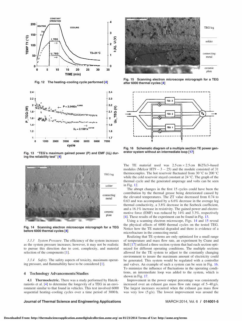
Using a scanning electron microscope, Figs. 14 and 15 revealthe physical effects of 6000 thermal cycles on the tested TEG.Notice how the TE material degraded and there is evidence of amicrofracture in the connecting metal.
Realizing that TE systems are only optimized for a small rangeof temperature and mass flow rate, an experiment by Crane andBell [17] utilized a three section system that had each section opti-mized for different operating conditions. The multiple sectionsallowed for the TE system to adjust to the constantly changingenvironment to insure the maximum amount of electricity couldbe generated. This system would be regulated with a controllerand valves. An example of such a system can be seen in Fig. 16.To minimize the influence of fluctuations in the operating condi-tions, an intermediate loop was added to the system, which isshown in Fig. 17.
Improvement in the power output percentage was consistentlyincreased over an exhaust gas mass flow rate range of 5–40 g/s.The largest increases occurred when the exhaust gas mass flowwas very low (5 g/s). The lowest improvement was around the
Fig. 12 The heating–cooling cycle performed [4]
Fig. 13 “TEG’s maximum gained power (P) and EMF (U0) dur-ing the reliability test” [4]
Fig. 14 Scanning electron microscope micrograph for a TEGbefore 6000 thermal cycles [4]
Fig. 15 Scanning electron microscope micrograph for a TEGafter 6000 thermal cycles [4]
Fig. 16 Schematic diagram of a multiple section TE power gen-erator system without an intermediate loop [17]
Journal of Thermal Science and Engineering Applications MARCH 2014, Vol. 6 / 014001-5
Downloaded From: http://thermalscienceapplication.asmedigitalcollection.asme.org/ on 01/23/2014 Terms of Use: http://asme.org/terms

exhaust gas mass flow rate of 20–25 g/s but increased as the massflow rate increased or decreased from this amount. The perform-ance improvements over traditional single section TE devices arein the range of 90% at low mass flow rates and 25% for high massflow rates. These data can be found in Fig. 18.
The total cycle energy recovered was measured on four differ-ent drive cycles for both a single section TE system and a threesection TE system. These drive cycles were FTP–75 city cycle,the HWFET highway cycle, the combined city and highway cycle,and the European NEDC drive cycle. The results found in Fig. 19show that the three section TE system outperforms the single sec-tion TE system for all four drive cycles because the three sectionTE system can be optimized for three different heat energy condi-tions instead of just one.
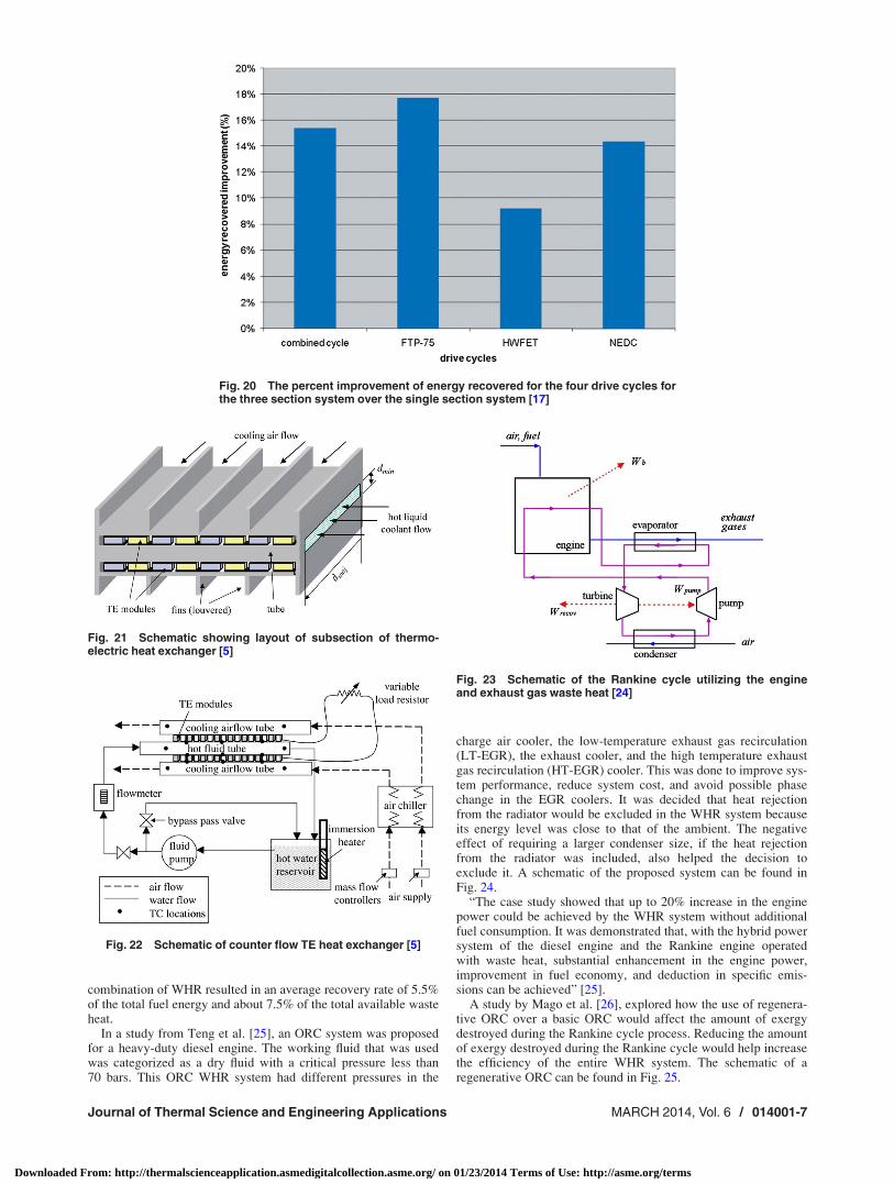
The performance improvement for the four different drivecycles can be found in Fig. 20, which illustrates an increase fromroughly 9�18%.
A system level optimization study by Mori et al. [5] that used avalidated model was performed to find the potential of a cross
flow heat exchanger that had hot reservoir characteristics of thecoolant flows of an IC engine. The system would take the place ofa traditional radiator and thus would have the cold reservoir con-sisting of ambient air flowing over the heat exchanger. The sche-matics of the simulated system can be seen in Figs. 21 and 22.“The results show that a net power output of 1 kW can beachieved for a modestly sized heat exchanger core such that thenet power density based on heat exchanger volume is 45 kW/m3.Optimization for a power/cost ratio objective function with a min-imum net power requirement of 1 kW indicated that the power percost can reach as high as 1.1 kW/$10,000” [5].
4.2 Rankine Cycle. A study conducted by Arias et al. [24]evaluated the potential energy recovery in a practical hybridimplementation. The Toyota Prius hybrid was used as inputs forthe vehicle/energy recovery model. It was found that the exhausttemperatures for this vehicle were lower than what was expected.This lower temperature accounted for a poor average recoveryrate of 0.8% of the total fuel energy and about 1.8% of the totalavailable waste heat. The system was modified to utilize the heatfrom the engine block, seen in Fig. 23. The engine block was usedto boil the working fluid in the power cycle and the high tempera-ture exhaust gases were then used to superheat the fluid. This
Fig. 17 The schematic for a multiple TE power generator sys-tem with an intermediate loop between the exhaust pipe andthe TE generator [17]
Fig. 18 The power output improvement (%) for a given exhaust gas mass flow(g/s) by using a three section system compared to a single section system [17]
Fig. 19 Comparing the total cycle energy recovered (W/h) forfour different drive cycles that used a single section system(optimized at 25 g/s) to that of a three section system (optimizedat 5, 10, and 20 g/s) [17]
014001-6 / Vol. 6, MARCH 2014 Transactions of the ASME
Downloaded From: http://thermalscienceapplication.asmedigitalcollection.asme.org/ on 01/23/2014 Terms of Use: http://asme.org/terms
combination of WHR resulted in an average recovery rate of 5.5%of the total fuel energy and about 7.5% of the total available wasteheat.
In a study from Teng et al. [25], an ORC system was proposedfor a heavy-duty diesel engine. The working fluid that was usedwas categorized as a dry fluid with a critical pressure less than70 bars. This ORC WHR system had different pressures in the
charge air cooler, the low-temperature exhaust gas recirculation(LT-EGR), the exhaust cooler, and the high temperature exhaustgas recirculation (HT-EGR) cooler. This was done to improve sys-tem performance, reduce system cost, and avoid possible phasechange in the EGR coolers. It was decided that heat rejectionfrom the radiator would be excluded in the WHR system becauseits energy level was close to that of the ambient. The negativeeffect of requiring a larger condenser size, if the heat rejectionfrom the radiator was included, also helped the decision toexclude it. A schematic of the proposed system can be found inFig. 24.
“The case study showed that up to 20% increase in the enginepower could be achieved by the WHR system without additionalfuel consumption. It was demonstrated that, with the hybrid powersystem of the diesel engine and the Rankine engine operatedwith waste heat, substantial enhancement in the engine power,improvement in fuel economy, and deduction in specific emis-sions can be achieved” [25].
A study by Mago et al. [26], explored how the use of regenera-tive ORC over a basic ORC would affect the amount of exergydestroyed during the Rankine cycle process. Reducing the amountof exergy destroyed during the Rankine cycle would help increasethe efficiency of the entire WHR system. The schematic of aregenerative ORC can be found in Fig. 25.
Fig. 20 The percent improvement of energy recovered for the four drive cycles forthe three section system over the single section system [17]
Fig. 21 Schematic showing layout of subsection of thermo-electric heat exchanger [5]
Fig. 22 Schematic of counter flow TE heat exchanger [5]
Fig. 23 Schematic of the Rankine cycle utilizing the engineand exhaust gas waste heat [24]
Journal of Thermal Science and Engineering Applications MARCH 2014, Vol. 6 / 014001-7
Downloaded From: http://thermalscienceapplication.asmedigitalcollection.asme.org/ on 01/23/2014 Terms of Use: http://asme.org/terms

The regenerative ORC produced higher thermal/exergy effi-ciencies, a higher degree of thermodynamic perfection, and alower total system exergy loss compared to the basic ORCsystem.
It was found that the evaporator is the component, in ORC sys-tems, with the highest influence coefficient and highest exergyloss with respect to the overall system exergy loss. The exergyloss was reduced in regenerative ORC systems from 77% to40.4% because the working fluid was more gradually warmed upby the presence of the feed-water heater.
The thermal and exergy efficiencies increase along with adecrease in system total exergy loss with the increase in the evap-orator pressure. The increased evaporator pressure will bring thetemperature of the organic fluid closer to the temperature of thehot gas entering the evaporator with heat transfer occurring over alower temperature difference.
5 Conclusions
The use of waste heat recovery systems in automobiles hasshown substantial potential to increase fuel economy. The two
main WHR systems for automotive applications were found to bethermoelectric generators and Rankine cycle electrical generators.The design considerations for these systems include; backpres-sure, weight, thermal power fluctuations, cold reservoir reliability,dc–dc converter loses, type of engine, coolant or exhaust energystreams, expense, complexity, and size. Additional considerationsfor thermoelectric material, longevity, and stress are needed forthermoelectric generators while working fluid selection, compo-nent design, system pressure, and safety are needed for Rankinecycles. Over the past 10 yr, these issues have been addressed by anumber of different case studies and advances in technologywhich will assist in making these techniques for waste heat recov-ery in automobiles economically and technologically a reality.
Nomenclature
CAC ¼ charge air coolerEGR ¼ exhaust gas recirculationEMF ¼ electromotive force
HT ¼ high temperatureIC ¼ internal combustionLT ¼ low temperature
ORC ¼ organic Rankine cycleP ¼ power
U0 ¼ electromotive forces ¼ entropyS ¼ Seebeck coefficientT ¼ operating temperature
TE ¼ thermoelectricTEG ¼ thermoelectric generator
WHR ¼ waste heat recoveryZT ¼ dimensionless figure of merit
j ¼ thermal conductivityr ¼ electrical conductivity
References[1] Chammas, R. E., and Clodic, D., 2005, “Combined Cycle for Hybrid Vehicles,”
Technical Report No. 2005-01-1171.[2] Yu, C., and Chau, K., 2009, “Thermoelectric Automotive Waste Heat Energy
Recovery Using Maximum Power Point Tracking,” Energy Conv. Manage., 50,pp. 1506–1512.
[3] Yang, J., and Stabler, F. R., 2009, “Automotive Applications of ThermoelectricMaterials,” J. Elec. Materials, 38, pp. 1245–1251.
Fig. 24 An ORC-WHR system with integrated low-temperature cooling loop [25]
Fig. 25 Schematic of a regenerative ORC [26]
014001-8 / Vol. 6, MARCH 2014 Transactions of the ASME
Downloaded From: http://thermalscienceapplication.asmedigitalcollection.asme.org/ on 01/23/2014 Terms of Use: http://asme.org/terms

[4] Hatzikraniotis, E., Zorbas, K. T., Samaras, I., Kyratsi, T. H., and Paraskevopou-los, K. M., 2009, “Efficiency Study of a Commercial Thermoelectric PowerGenerator Teg Under Thermal Cycling,” J. Elec. Materials, 39, pp. 2112–2116.
[5] Crane, D. T., and Jackson, G. S., 2004, “Optimization of Cross Flow HeatExchangers for Thermoelectric Waste Heat Recovery,” Energy Conv. Manage.,45, pp. 1565–1582.
[6] Ringler, J., Seifert, M., Guyotot, V., and Hubner, W., 2009, “Rankine Cycle forWaste Heat Recovery of IC Engines,” Technical Report No. 2009-01-0174.
[7] Stobart, R., and Milner, D., 2009, “The Potential for Thermo-Electric Regenera-tion of Energy in Vehicles,” Technical Report No. 2009-01-1333.
[8] Mori, M., Yamagami, T., Oda, N., Hattori, M., Sorazawa, M., and Haraguchi,T., 2009, “Current Possibilities of Thermoelectric Technology Relative to FuelEconomy,” Technical Report No. 2009-01-0170.
[9] Rowe, D., 2006, Thermoelectrics Handbook: Macro to Nano, CRC Press, BocaRaton, FL.
[10] Headings, L. M., Midlam-Mohler, S., Washington, G. N., and Heremans, J. P.,2008, “High Temperature Thermoelectric Auxiliary Power Unit for AutomotiveApplications,” ASME 2008 Conference on Smart Materials, Adaptive Struc-tures & Intelligent Systems, October 28–30, Ellicott City, MD, Paper No. SMA-SIS2008-610.
[11] LaManna, J., Ortiz, D., Livelli, M., Haas, S., Chikwem, C., Ray, B., andStevens, R., 2008, “Feasibility of Thermoelectric Waste Heat Recoveryin Large Scale Systems,” Technical Report No. IMECE2008-68676, Oct.31–Nov. 6.
[12] Srinivasan, M., and Praslad, S. M., 2005, “Advanced Thermoelectric EnergyRecovery System in Light Duty and Heavy Duty Vehicles: Analysis on Techni-cal and Marketing Challenges,” International Conference on Power Electronicsand Drives Systems, PEDS 2005, Vol. 2, pp. 977–982.
[13] Saqr, K. M., Mansour, M. K., and Musa, M. N., 2008, “Thermal Design ofAutomobile Exhaust Based Thermoelectric Generators: Objectives andChallenges,” Int. J. Auto. Technol., 9, pp. 155–160.
[14] Hung, T. C., Shai, T. Y., and Wang, S. K., 1997, “A Review of Organic Ran-kine Cycles (ORCs) for the Recovery of Low-Grade Waste Heat,” Energy, 22,pp. 661–667.
[15] Liu, B.-T., Chien, K.-H., and Wang, C.-C., 2004, “Effect of Working Fluids onOrganic Rankine Cycle for Waste Heat Recovery,” Energy, 29, pp. 1207–1217.
[16] Schuster, A., Karellas, S., Kakaras, E., and Spliethoff, H., 2009, “Energetic andEconomic Investigation of Organic Rankine Cycle Applications,” App. Ther-mal Eng., 29, pp. 1809–1817.
[17] Crane, D. T., and Bell, L. E., 2009, “Design to Maximize Performance of aThermoelectric Power Generator With a Dynamic Thermal Power Source,”ASME J. Energy Resour. Technol., 131, p. 012401.
[18] Crane, D. T., Jackson, G. S., and Holloway, D., 2001, “Towards Optimizationof Automotive Waste Heat Recovery Using Thermoelectrics,” SAE TechnicalPaper, Technical Report No. 2001-01-1021.
[19] Wojciechowski, K. T., Schhmidt, M., Zybala, R., Merkisz, J., Fuc, P., andLijewski, P., 2009, “Comparison of Waste Heat Recovery From the Exhaust ofa Spark Ignition and a Diesel Engine,” J. Elec. Materials, 39, p. 2034–2038.
[20] Teng, H., Regner, G., and Cowland, C., 2006, “Achieving High Engine Effi-ciency for Heavy-Duty Diesel Engines by Waste Heat Recovery Using Super-critical Organic-Fluid Rankine Cycle,” Technical Report No. 2006-01-3522.
[21] Smith, K., and Thornton, M., 2009, “Feasibility of Thermoelectrics for WasteHeat Recovery in Conventional Vehicles,” Technical Report, National Renew-able Energy Laboratory, Paper No. NREL/TP-540-44247.
[22] Yang, J., 2005, “Potential Applications of Thermoelectric Waste Heat Recoveryin the Automotive Industry,” ICT 2005, 24th International Conference on Ther-moelectrics, June 19–23, Clemson, SC.
[23] Hussain, Q. E., Brigham, D. R., and Maranville, C. W., 2009, “ThermoelectricExhaust Heat Recovery for Hybrid Vehicles,” Technical Report No. 2009-01-1327.
[24] Arias, D. A., Shedd, T. A., and Jester, R. K., 2006, “Theoretical Analysis ofWaste Heat Recovery From an Internal Combustion Engine in a Hybrid Vehi-cle,” Technical Report No. 2006-01-1605.
[25] Teng, H., Regner, G., and Cowland, C., 2007, “Waste Heat Recovery of Heavy-Duty Diesel Engines by Organic Rankine Cycle Part I: Hybrid Energy Systemof Diesel and Rankine Engines,” Technical Report No. 2007-01-0537.
[26] Mago, P. J., Srinivasan, K. K., Chamra, L. M., and Somayaji, C., 2008, “AnExamination of Exergy Destruction in Organic Rankine Cycles,” Int. J. EnergyRes., 32, pp. 926–938.
Journal of Thermal Science and Engineering Applications MARCH 2014, Vol. 6 / 014001-9
Downloaded From: http://thermalscienceapplication.asmedigitalcollection.asme.org/ on 01/23/2014 Terms of Use: http://asme.org/terms