review on thermal noise related activities in perugia flavio travasso n.i.p.s. laboratory, dip....
Post on 19-Dec-2015
220 views
TRANSCRIPT
Review on thermal noise related activities in Perugia
Flavio Travasso
N.i.P.S. Laboratory, Dip. Fisica – Università di Perugia and INFN Perugia
Virgo - Perugia

Activities in Perugia1. Cryogenic Coating Measurements:
– Changes in the coating Фcoat(T): to find a change in the coating changing the temperature
– Different coatings: to measure the different loss angles of different coatings
• Measured Slabs (3 samples – provided and coated by LMA-Virgo Lion):– Uncoated Slab– Titania doped tantala coated slab (slab A)– Cobalt doped tantala coated slab (slab B)
• Dimension: – A & B: 41mm x 5 mm x 104 μm– Uncoated: 45mm x 5 mm x 104 μmDifferent frequencies
• Coatings:– A: 520 nm TiO2 doped Ta2O5 mono-layer coating– B: 500 nm Co doped Ta2O5 mono-layer coating
2. Fused silica Substrate cryogenic behavior
– Experimental activity: • about 20 modes studied for 3 uncoated slabs
– Theoretical activity: For the amorphous material the classical laws used for the crystalline materials are
not so easy to use or to support that’s why is usefull and hard find a:• theory to explain the Ф frequency trend of the modes at each temperature above
140K• theory to explain the Ф temperature peak around 20K

Activities in Perugia3. Silicate bonding:
– Different materials: studies for future cryogenic suspension
– Ice and flame: to see the answer of the SB to the thermal stress
4. Monolithic suspension:– Fiber production: flame
– Monolithic suspension Collaboration: see Puppo Paola talk
5. Non equilibrium thermal noise:- Purpose:
- to measure the dynamics of a perturbed system at thermal equilibrium
- to improve the sensibility of an optical system
- Work in progress: to check the sensibility with the new cavity to stabilize the laser in frequency

Coatings

Sample holds

Labview Interface
Ni
He
Ni
He
He
Cu
Laser
HV Amplifier
Clamp tightened using a spring
Cooling down rate: 1-2 K/h
…to avoid particular thermal/mechanical stress
Measurement Apparatus

Summury on coating activity
Work in progress:
• To improve the measurements of coating at low temperature we plan on testing the same coating on new substrates • To design a new clamping system and/or new geometry for the samples: see the “New clamping system” session• New materials for the coating
Coating Results:
• The coating ФCoat is almost costant in the temperature range of 300K-90K
• The Cobalt doped tantala coating shows a ФCoat better than the titania doped tantala coating:
ФCoat Mean Value = 3.4E-3 ± 1E-3
ФCoat Mean Value = 7E-4 ± 2E-4
• The measurements are limited by the substrates losses… (see Work in progress)
0 50 100 150 200 250 300
1E-5
1E-4
1E-3
0.01
Temperature [K]
Uncoated slab Coated slab A Coating
0 50 100 150 200 250 300
1E-5
1E-4
1E-3
0.01
Temperature [k]
Uncoated slab Coated slab B Coating
..too high

Fused Silica Substrates at low temperature
0 50 100 150 200 250 300
1E-5
1E-4
1E-3
@ 290Hz
[ra
d]
Temperature [K]
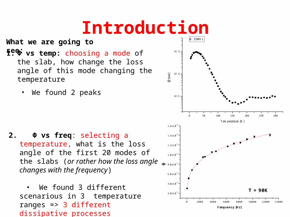
Introduction1. Φ vs temp: choosing a mode of the slab,
how change the loss angle of this mode changing the temperature
• We found 2 peaks
2. Φ vs freq: selecting a temperature, what is the loss angle of the first 20 modes of the slabs (or rather how the loss angle changes with the frequency)
• We found 3 different scenarious in 3 temperature ranges => 3 different dissipative processes
0 2000 4000 6000 8000 10000 12000 14000
2.0x10⁻⁵
4.0x10⁻⁵
6.0x10⁻⁵
8.0x10⁻⁵
1.0x10⁻⁴
1.2x10⁻⁴
1.4x10⁻⁴
1.6x10⁻⁴
Frequency [Hz]
T = 90K
What we are going to see:

Summary of situations
The frequency dependent trend is clear…
…but it’s also clear that the data for T<30K have a slope smaller than the data between 140K-40K.
0 5 10 150.0
0.5
1.0
1.5
0 5 10 15
1
2
3 250K 240K 230K
105 x
[r
ad] [kHz]
15K
30K
50K
64K
90K
4.6K
103 x
[kHz]

Power law (Kramers formula)
BfA*
0 2000 4000 6000 8000 10000 12000 14000
2.0x10⁻⁵
4.0x10⁻⁵
6.0x10⁻⁵
8.0x10⁻⁵
1.0x10⁻⁴
1.2x10⁻⁴
1.4x10⁻⁴
1.6x10⁻⁴
Frequency [Hz]
T = 90K
What we can do?
We can fit the data with a general power law (the fist one) and compare that with few specific power laws coming from different physical models. In literature the most accredited one is the double well potetial model
…that comes from a double well potential model
B
B
BCA
KT
TB
fBC
)2(**with
)*2(**
0
0
0

0 50 100 150 200 2500.0
0.1
0.2
0.3
0.4
Exp
onen
t p
ower
law
: B
Temperature [K]
Exponent of power law: B
KT
TB
0
Above 140K the loss angle appears to be NOT frequency dependent
The freq. Dependent process is becoming more active
These results are interesting because
1. In literature the explored frequency range is 500Hz-MHz (there are no infos on our frequency range)
2. In literature K = 0 …we have to consider another process to improve the actual physical models
A different dissipative mechanism comes into play: dissipative quantum tunnelling , that is quantum tunnelling assisted by thermal fluctuations
Sharp transition? System instability? Work in progress…
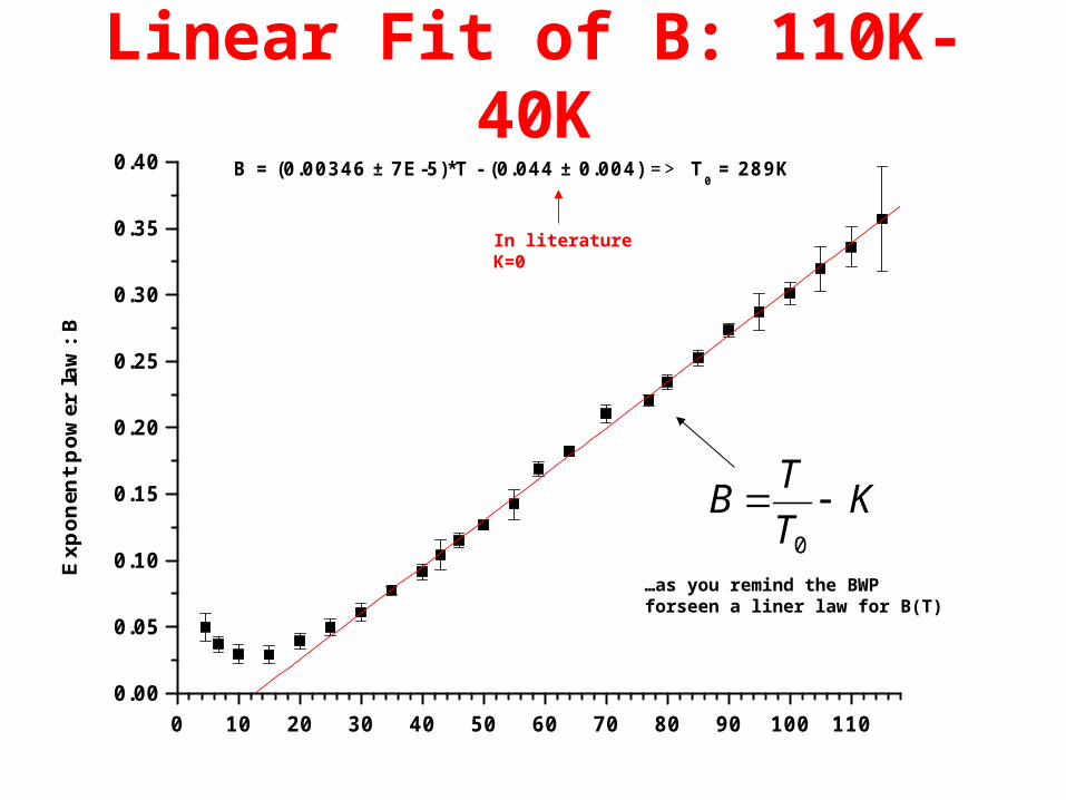
Linear Fit of B: 110K-40K
KT
TB
0
…as you remind the BWP forseen a liner law for B(T)
0 10 20 30 40 50 60 70 80 90 100 1100.00
0.05
0.10
0.15
0.20
0.25
0.30
0.35
0.40
Exp
onen
t po
wer
law
: B
B = (0.00346 ± 7E-5)*T - (0.044 ± 0.004) => T0 = 289K
In literature K=0

0 20 40 60 80 100 120 140-1.0x10⁻⁴
0.0
1.0x10⁻⁴
2.0x10⁻⁴
3.0x10⁻⁴
4.0x10⁻⁴
5.0x10⁻⁴
6.0x10⁻⁴
7.0x10⁻⁴
8.0x10⁻⁴
Am
plit
ude
pow
er la
w:
A
T (K)
Fit A
BBCA )2(** 0Using for B the value evaluated in the previous slide
The losses are higher than what forseen by the double well potential model: 2 competive dissipative processes
At low temperature (T<30K) the data have a different trend respect the fits: a different dissipative mechanism comes into play, dissipative quantum tunnelling , that is quantum tunnelling assisted by thermal fluctuations

CommentsSiO2 Results: The measurements show a clear behaviour with temperature:
- an almost constant loss angle above 140K - between 140K and 30K the loss angle has a significant increase that can be interpreted by calling for thermally activated relaxation dynamics (in multi-stable potentials) - below 30K the loss angle starts decreasing: the thermally activated dissipation is less effective and a different dissipative mechanism starts driving the dynamics (quantum tunnelling effects become active at very low temperature… that is quantum tunnelling assisted by thermal fluctuations ) - The clamp adds a quite costant dissipation and has a smoothing effect
Work in progress:A new refined dynamical model for the interpretation of the losses in the low frequency and temperature region is in preparation (F. Marchesoni) In literature the most accredited model is the double well potetial model deriving from a lot of different concurrent processes (tetrahedron links that rotate from an quasi-equilibrium state to another, region of collaboration defects => the dimension of those regions define the time scale (energy activation) of the process…and so on) and those make the exponent B dipendent by the temperature. But for the DWP model it´s not important the physical reason of the processes but just the existence of 2 or more quasi-static position…that’s the nice thing and the limit of that theory Bibliography:
Low-frequency internal friction in silica glassTravasso,F. /Amico,P. /Bosi,L. /Cottone,F. /Dari,A. /Gammaitoni,L. /Vocca,H./Marchesoni,F. 2007 - Submitted

New clamping system
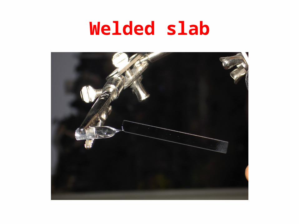
Welded slab

60 80 100 120 140 160 180 200 220 240 260 280 300 320
1E-7
1E-6
1E-5
1E-4
290Hz
Temperature [K]
60 80 100 120 140 160 180 200 220 240 260 280 300 3201E-7
1E-6
1E-5
1E-4
880Hz Old clamp New clamp
Temperature [K]
The clamp adds a quite costant dissipation and has a smoothing effect
The 2 slabs have the same trend and the same slope for T<190K
Work in progress
I would test this new clamping system on a coated sample in order to see if the old copper clamp add only a costant loss to each sample.
If so, it should be better to use the old clamp because for the new clamp we have to weld the sample using a flame risking to damage the sample

0 100 200 300
10-6
10-5
10-4
10-3 new
[ra
d]
T [K]
old 290Hz 880Hz
The fit at low temperature is the Kramers formula (see slide 14) while the fit at high temperature is the error function. Here is clear the extra loss added by the copper clamp

CommentsClamps: The copper clamp clearly adds an extra loss to the loss angle
We would evaluate that extra loss in order to use that clamp with the very thin sample: the flame could be destructive (no problem with the sample with a thickness of 1 mm at least)
Work in progress:
New data on the coated samples with the new clamping system
New geometry for the samples: cylindrical windows

Heating data

0 100 200 300
10-5
10-4
10-3
0 100 200 300
10-5
10-4
10-3
= 3.8kHz
[ra
d]
T [K]
46Hz290Hz6.2kHz
0 100 200 300
10-5
10-4
10-3
[ra
d]
T [K]
46Hz 290 Hz 800 Hz 3800 Hz 6200 Hz 12000 Hz
The sample was heating to 340K
The loss angle shows a flat region till this temperature
Silicate bonding
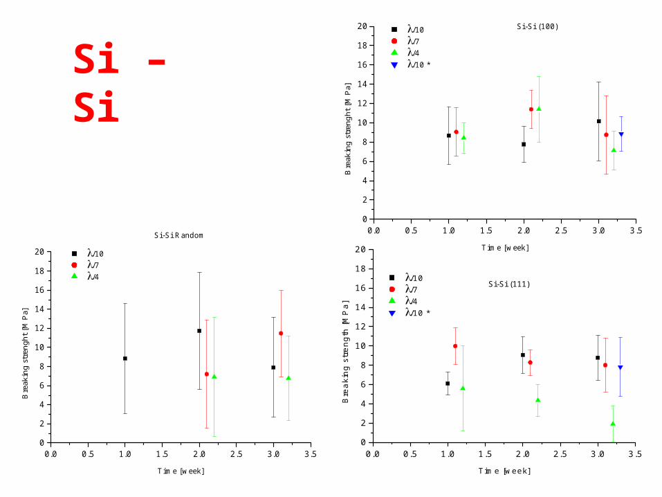
0.0 0.5 1.0 1.5 2.0 2.5 3.0 3.5
0
2
4
6
8
10
12
14
16
18
20
Si-Si Random
Bre
akin
g st
reng
ht [
MPa
]
Time [week]
/10 /7 /4
0.0 0.5 1.0 1.5 2.0 2.5 3.0 3.50
2
4
6
8
10
12
14
16
18
20 Si-Si (100) /10 /7 /4 /10 *
Bre
akin
g st
reng
ht [
MPa
]
Time [week]
Si – Si
0.0 0.5 1.0 1.5 2.0 2.5 3.0 3.50
2
4
6
8
10
12
14
16
18
20
/10 /7 /4 /10 *
Si-Si (111)
Bre
aki
ng
str
en
gth
[MP
a]
Time [week]
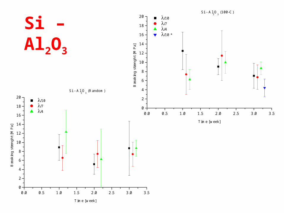
0.0 0.5 1.0 1.5 2.0 2.5 3.0 3.50
2
4
6
8
10
12
14
16
18
20Si - Al
2O
3 (100-C)
/10 /7 /4 /10 *
Bre
akin
g st
reng
ht [
MPa
]
Time [week]
Si – Al2O3
0.0 0.5 1.0 1.5 2.0 2.5 3.0 3.50
2
4
6
8
10
12
14
16
18
20Si - Al
2O
3 (Random)
/10 /7 /4
Bre
akin
g st
reng
ht [
MPa
]
Time [week]

Al2O3 – Al2O3
0.0 0.5 1.0 1.5 2.0 2.5 3.0 3.50
2
4
6
8
10
12
14
16
18
20Al
2O
3 - Al
2O
3 (C-C)
/10 /7 /4 /10 *
Bre
akin
g st
reng
ht [
MPa
]
Time [week]
0.0 0.5 1.0 1.5 2.0 2.5 3.0 3.50
2
4
6
8
10
12
14
16
18
20Al
2O
3 - Al
2O
3 (Random)
/10 /7 /4
Bre
akin
g st
reng
ht [
MPa
]
Time [week]

There is no evidence thet the breaking strength has a clear trend over the time or over the lambda: that´s why we report here the mean value over the samples
Mean Values

Work in progress
FLAME The SB seems to be very sensitive to the high temperature. Few test are mede using samples cooking in an oven an samples with a SB of few month and welding in a very slow way
ICE We made just one test on a Silicon-Sapphire SB We put the sample in a liquid nitrogen tank for few minutes. That sample showed the usual breaking strength

Comments
1. The silicate bonding seems to work very well if one of the material we want to glue has the Si atom in its formula
2. There is no evidence that the breaking strength has a real trend with the time or with the lambda

Fiber production for the Monolithic Suspension

Fiber production machines

The facility at the west The facility at the west middle arm building, is a middle arm building, is a newer copy of the Perugia newer copy of the Perugia one.one.The facility is now The facility is now operative.operative.As soon as the laser COAs soon as the laser CO22 will be operative we will will be operative we will compare the two results.compare the two results.
Cascina fiber pulling machine
The fused silica bar is contemporary heated The fused silica bar is contemporary heated in the center part of the “flame stove” and in the center part of the “flame stove” and cooled near it to limit the melted volume cooled near it to limit the melted volume (better control of the fiber tapers). We will (better control of the fiber tapers). We will install an upgrade of it in few days…install an upgrade of it in few days…

Cascina fiber pulling machine (2)
0
200
400
600
800
1000
1200
1400
1600
0 50 100 150distance along the fibre [mm]
dia
met
er [
um
]

Validation procedure
It is possible to:It is possible to:
• rearrange the surface defects and cracks;rearrange the surface defects and cracks;
• weld fibers in the low diameter part weld fibers in the low diameter part accurately;accurately;We are evaluating the optimum diameter for We are evaluating the optimum diameter for the welding to minimize the losses induced.the welding to minimize the losses induced.
80 80 m fiberm fiberWe improved our control We improved our control on the fiber surface on the fiber surface quality using a portable quality using a portable very thin flame welding very thin flame welding machine. It is possible to machine. It is possible to check and repair the fiber check and repair the fiber surface and increase the surface and increase the validated fiber quality.validated fiber quality.

A 3D Laser Caliper is A 3D Laser Caliper is used to measure the used to measure the diameter and shape diameter and shape of the fiber produced.of the fiber produced.
It is possible to verify It is possible to verify the circularity of the the circularity of the fiber section and to fiber section and to measure the measure the diameter with a diameter with a precision up to 0.1 precision up to 0.1 microns.microns.
Validation procedure (2)

..for the monolithic suspension status see the Paola Puppo´s
talk

Non-stationary thermal noise

X
ModulatoreElettro-ottico
CavitàMisura
Pbs
Segnale inriflessione
Nd-Yag
/4
/2
Pico-motore
Schema ottico
P=10-6 mbar
12.5 MHz
1064 nm
Non-stationary thermal noise
Purpose To understand the dynamics of a perturbed system at thermal equilibrium or rather:
- read directly the thermal noise of a thin slab
- reduce a TN peak with a sine in counter-phase with the oscillation of the slab
- see how the peak comes back to the equilibrium: it should absorb energy from the other modes reducing the thermal noise
- see if the system changes its dynamics
- to improve the sensibility of an optical system driving the dinamics of the optics

1064 nm
12.5 MHz
X
X
Nd-YagModulatoreElettro-ottico
/2
Pico-motore
CavitàMisura
/4telescopio
Pbs
Cavità stabilizzazione
Segnale intrasmissione
Segnale inriflessione
Segnale inriflessione
P=10-6 mbar
Cellapeltier
-0.02 0.00 0.020
1
2
3
4
Vol
t
t [s]
-0.10 -0.05 0.00 0.05 0.10 0.15-0.4
-0.2
0.0
0.2
0.4
t=0.0733 sV/t= 65.2
Vol
t
t [s]
Non-Stationary Thermal Noise: stabilized cavity

Frequency [Hz]
Dis
pla
cem
ent
[m]
Not stabilized cavity Electronic Noise Stabilized Cavity
New sensitivity

CommentsResults:
Without the cavity to stabilized the laser it´s possible to see the peaks, to reduce their amplitude and to see how the system comes back to the thermal equilibrium => the dynimics of the system changes:
• there is a crosstalk between the modes => it´s very hard to understand if the perturbed peak is stealing energy from the slab improving the sensibility on the other region: new exciter
• the rigidity of the slab seems to change: if we could understand how to change this parameter we could move the peaks in order to free a region of the spectrum with a particulare interest
Work in progress:
To test the new stabilized cavity to see directly the thermal noise

The End