revised concrete technology book -by sri p. suresh
TRANSCRIPT
CONCRETE FOR
DURABLE
STRUCTURES
P.SURESH.B.Tech.
PREFACE
This small booklet is prepared for the information of (R&B) Engineers who are involved in making of concrete for structures. The intention is to compile the required information regarding concrete from relevant IS/IRC codes, as many codes are not readily available for reference. Many of the senior Engineers might be well versed with the codal provisions. But the young Assistant Executive Engineers do not have required practical experience and knowledge of codal provisions.
In order to have some basic idea of concrete technology this booklet is prepared. Mistakes if any noticed in this booklet may be informed for correction.
P.SURESHDeputy Executive Engineer
(R&B) Sub division, Udayagiri.CELL NO: 9440818349

INDEX
From TO
1) Basics of concrete technology & Definitions 1 4
2) Materials 5 15
3) Cement concrete mix design 15 18
4) Proportioning of materials by weight 18 20
5) Water –cement ratio 21 25
6) Fabrication of reinforcement 25 29
7) Different grades of concrete 29 31
8) Preparation of form work 31 34
9) Preparation of concrete 35 37
10) Under water concreting & Hot weather concreting 37 41
11) Summary of Quality control tests 42 45
12) Preparation of C.C. Cubes &Slump test 46 50
13) Cement concrete pavements 51 57
14) Myths & Facts about concrete 58 59

1
1) BASICS OF CONCRETE TECHNOLOGY
It is a known fact that concrete is a structure of four components viz., (a) Cement, (b)
Water, (c) Coarse aggregates and (d) Fine aggregates. The materials when mixed with water,
forms calcium silicates and hardens upon reaction of cement and water. Now-a-days concrete
was changed a lot with more number of ingredients and as many as ten materials as detailed
below.
a) Fly ash (b) Ground granulated blast furnace slag (c) Silica fume (d) Rice husk ash (e)
Metakeoline,(f) Plasticizers, (g) Super plasticizers, (h) Synthetic (Polymeric) fibers (i) Steel
fibers (j) Air entraining agent.
Out of the above, the 5 items from (a) to (e) are called mineral admixtures, which are
used as partial replacement of cement. The use of above admixtures has distinct advantage
from partial replacement of cement, increase in compressive strength and workability at the
time of placing concrete. The other items mentioned plasticizers and super plasticizers are
used to increase the workability of concrete mix without increasing the water content in the
mix. These are very useful in high grades of concrete of M-40 and above to attain the
required concrete strength. The items of synthetic fibers, steel fibers are used for increase in
compressive strength of concrete and ductility and fatigue life of plain concrete. The item of
an air entraining agent is used for making of concrete in freezing weather to counter the
freezing and thawing effect. Each of the material used in concrete is having its own
advantages from the conventional four components concrete. The usage of different
materials is to be judged carefully depending on the requirement of concrete.
DEFINITIONS & TERMINOLOGY
Characteristic Compressive Strength of Concrete (fck)
The characteristic compressive strength is defined as the strength of concrete, below which
not more than 5% of test results are expected to fall.
Coarse Aggregate:

2
Aggregate most of which is retained on 4.75mm IS sieve or a portion of an aggregate
retained on 4.75mm sieve.
Fine Aggregate:
Aggregate most of which passes 4.75mm IS sieve.
Hydraulic Cement:
It is a finely ground material which on addition of requisite quantity of water is capable of
hardening both under water and in air by chemical reaction of water and is also capable of
binding together appropriate materials viz., coarse aggregate and fine aggregate to make a
solid mass after requisite curing.
Water Cement Ratio:
It is defined as the ratio of weight of water in a concrete mix exclusive of water absorbed by
aggregates and weight of cement in the concrete of one cum. The minimum water cement
ratio is 0.30 and maximum water cement ratio is 0.50 for structural concrete.
Single Sized Coarse Aggregate:
It is the aggregate which contains only one size of aggregate either 40mm, 20mm or 10mm.
Graded Aggregate:
It is the aggregate which contains different sizes of aggregate, which gives dense concrete
mix.
Grades of Concrete:
The standard practice of representing a concrete mix is ‘M’ followed by a number. In this
notation, M represents the concrete mix and the number suffixed represents characteristic
compressive strength of concrete after 28 days of curing.
For example,M40 Grade: It represents a concrete mix whose compressive strength after 28 days
of curing is 40 N/mm2 (40MPa) when tested over 150mm size cubes.
Nominal Mix Concrete:
It is a traditional mix of concrete in which the materials viz. cement, fine aggregate and coarse
aggregate are proportioned in a particular proportion (1.50 to 2.0) between coarse aggregate
and fine aggregate.
3
For example, CC (1:2:4) It represents a concrete mix which contains 1 part of cement, 2 parts
of fine aggregate (sand) and 4 parts of coarse aggregate (metal or chips). It assigns no specific
compressive strength of concrete. This involves higher cement content and uneconomical.
DESIGN MIX CONCRETE
It is a concrete mix which is designed in the laboratory for a specific compressive strength of
concrete required in the field. Concrete mix design means selecting the proportions of
different ingredients on the basis of their absolute volume of concrete per one cum in the
most economical way for the specified strength. The objective of proportioning concrete
mixes is to arrive most economical and practical combinations and proportions of different
ingredients to produce concrete that will meet the requirement of compressive strength,
workability and durability.
Now-a-days, the use of nominal mix concrete has been limited to unimportant
concrete items. Nominal mix concrete can be used for M15 and M20 grades of concrete only.
The grades of concrete higher than M20Grade must be design mix concrete only.
Workability:
It is the property of concrete which determines the amount of useful internal work necessary
to produce complete compaction.
Slump of Concrete:
It is the term used for specifying the workability of fresh concrete at the time of placing. It is not related in
any way to the compressive strength of concrete.
Flexural strength of concrete:
It is the tensile strength of concrete in bending and is related to characteristic compressive strength of
concrete. This is given by
fcr = 0.70 √fck
This term is useful in plain jointed cement concrete pavements as this is the main design parameter to
be satisfied under wheel loads. The minimum flexural strength required is 4.50 N/mm2 (4.50MPa) for
C. C. pavement. For rural road C. C. pavements, the minimum flexural strength required is 3.80
N/mm2.
4
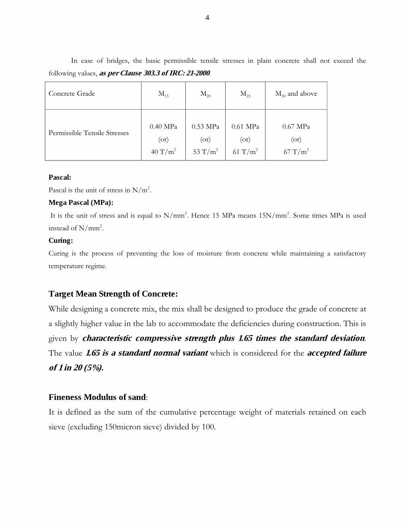
In case of bridges, the basic permissible tensile stresses in plain concrete shall not exceed the
following values, as per Clause 303.3 of IRC: 21-2000.
Concrete Grade M15 M20 M25 M30 and above
Permissible Tensile Stresses 0.40 MPa
(or)
40 T/m2
0.53 MPa
(or)
53 T/m2
0.61 MPa
(or)
61 T/m2
0.67 MPa
(or)
67 T/m2
Pascal:
Pascal is the unit of stress in N/m2.
Mega Pascal (MPa):
It is the unit of stress and is equal to N/mm2. Hence 15 MPa means 15N/mm2. Some times MPa is used
instead of N/mm2.
Curing:
Curing is the process of preventing the loss of moisture from concrete while maintaining a satisfactory
temperature regime.
Target Mean Strength of Concrete:
While designing a concrete mix, the mix shall be designed to produce the grade of concrete at
a slightly higher value in the lab to accommodate the deficiencies during construction. This is
given by characteristic compressive strength plus 1.65 times the standard deviation.
The value 1.65 is a standard normal variant which is considered for the accepted failure
of 1 in 20 (5%).
Fineness Modulus of sand:
It is defined as the sum of the cumulative percentage weight of materials retained on each
sieve (excluding 150micron sieve) divided by 100.

5
2) MATERIALS
(A) CEMENT:
Out of all components of concrete, cement is the prime and important material, which
directly influences the strength of concrete. Hence we must be very careful regarding the
quality of cement proposed for use in concrete. The following types of cement are generally
used.
i) Ordinary Portland Cement 33 grade, 43 grade, 53 grade (OPC)
ii) Portland Pozzolona Cement (Fly ash based)
iii) Portland Slag Cement.
We generally adopt ordinary Portland cement (OPC) in our Department works. In case of
cement, the grade numbers 33/43/53 represents the compressive strength of cement at 28
days curing when tested over 70.6mm cubes prepared with cement mortar (1:3) using
Ennur standard sand. So, OPC 33 refers to cement, having a compressive strength of 33
N/mm2 after 28 days of curing when tested over 70.6mm cubes.
Out of the three grades of ordinary Portland cement (OPC), the manufacture of 33 grade
cement was stopped. Few factories are manufacture 43 grade cement. Almost all the factories
manufacture only 53 grade cement, as it involves no additional expenditure to the factories.
The strength of cement is increased by simply fine grinding the materials. Even though the
OPC 53 grade gains early strength and more strength at 28 days, it has got the following
disadvantages.
The heat of hydration is too high and curing has to be started as early as within 10
hours after laying of concrete. If proper curing methods are not employed, micro cracks
develop due to high heat of hydration. In practice, concrete is laid today, dikes of cement
mortar (small bunds) are formed tomorrow and to allow hardening of dikes, curing will be
started day after tomorrow. Thus, the actual process of curing starts only after lapse of 36
hours or more. By that time the heat of hydration increases alarmingly and cracks develop.
And finally, the damage to the concrete goes unnoticed. It is a fact that concrete requires
more water from the first 10 hours to 24 hours. In view of the above abnormal delay in
curing, the usage of 53 grade cement should be judged carefully.

6
The presence of micro cracks due to delayed curing causes lot of problems, regarding
durability. The reinforcement gets corroded due to ingress of moisture through these cracks
and structural strength gets decreased, finally leading to failure of structures. Lot of
discussion is going on around the world, regarding the rate of failure of recently
constructed structures after 1980, than the structures constructed prior to 1980.
As we are left with no other alternative of except using OPC 53 grade, due to the non-
availability of other grades of OPC, it is desirable to start curing as early as possible, after 12
hours of laying of concrete, without any delay to safeguard the life of concrete structures.
The Portland Pozzolona Cement (fly ash based) is presently adopted in
C. C. pavements, partially replacing the cement with fly ash. IRC: 44–2008 recommends a
maximum dosage of 20% by mass of cement. The use of Portland Pozzolona Cement is
having the following deficiencies.
The gain of strength with PPC is low when compared to OPC in early days. But the
compressive strength at 28 days is almost same for both types of cement.
The real problem comes with curing. Now-a-days it became a practice to stop curing
on the pretext that 70% of the strength is achieved in 7 days, and in order to remove the
centering early, for speedy execution of work to reuse the formwork. Sometimes, adequate
quantity of quality water for curing will not be available in dry seasons. Due to the above
problems, if curing is stopped at 10 days or so, the concrete laid with PPC will achieve for
less strength and causes problems in durability criterion. So, curing must be done for 28
days, when PPC is used to achieve the required strength. This does not mean, curing for
OPC can be stopped early. It is my personal opinion, curing must be done for 28 days,
by ponding, irrespective of type of cement used in spite of codal specification of 14 days
curing, to achieve the required strength and to arrive long lasting durable concrete structures
(Curing is the cheapest way to achieve highest strength).
The concrete prepared with PPC will gain more strength even after 28 days
considerably. Some cores taken in the CC pavement laid with PPC after 65 days gave the
compressive strength up to 60 N/mm2 against the required compressive strength of 30
N/mm2.
7
From the above, we can clearly say, curing for prolonged period of not less than28
days will help in many ways in the strength and durability criterion of concrete structures.
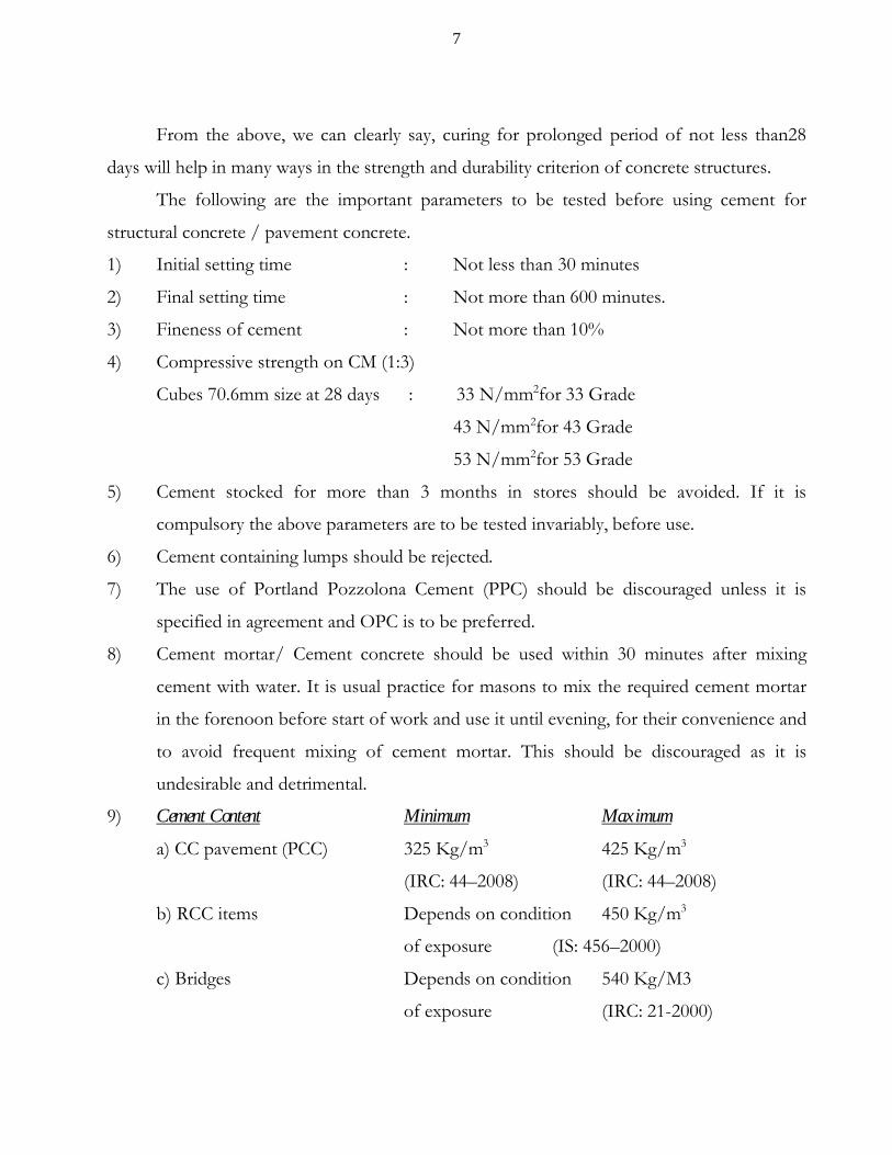
The following are the important parameters to be tested before using cement for
structural concrete / pavement concrete.
1) Initial setting time : Not less than 30 minutes
2) Final setting time : Not more than 600 minutes.
3) Fineness of cement : Not more than 10%
4) Compressive strength on CM (1:3)
Cubes 70.6mm size at 28 days : 33 N/mm2for 33 Grade
43 N/mm2for 43 Grade
53 N/mm2for 53 Grade
5) Cement stocked for more than 3 months in stores should be avoided. If it is
compulsory the above parameters are to be tested invariably, before use.
6) Cement containing lumps should be rejected.
7) The use of Portland Pozzolona Cement (PPC) should be discouraged unless it is
specified in agreement and OPC is to be preferred.
8) Cement mortar/ Cement concrete should be used within 30 minutes after mixing
cement with water. It is usual practice for masons to mix the required cement mortar
in the forenoon before start of work and use it until evening, for their convenience and
to avoid frequent mixing of cement mortar. This should be discouraged as it is
undesirable and detrimental.
9) Cement Content Minimum Maximum
a) CC pavement (PCC) 325 Kg/m3 425 Kg/m3
(IRC: 44–2008) (IRC: 44–2008)
b) RCC items Depends on condition 450 Kg/m3
of exposure (IS: 456–2000)
c) Bridges Depends on condition 540 Kg/M3
of exposure (IRC: 21-2000)

8
(B) STEEL:
Different types of steel generally used in concrete are
i) Mild Steel or S240
ii) HYSD Steel or S415
iii) TMT Bars or S500
The usage of mild steel in structural RCC members is dispensed. They are used as
dowel bars in contraction / expansion joints of CC pavement. Mild steel is also referred
to as S240, which means steel whose characteristic yield strength is 240 N/mm2. The
characteristic yield strength is assumed as minimum yield stress (or) 0.20 percent
proof stress.
Similarly, HYSD steel means high yield strength deformed bars or S415, whose
characteristic yield strength is 415 N/mm2.
The TMT bars are the new innovation in steel. The word TMT means thermo
mechanically treated bars. The production of TMT bars involves quenching and tempering
process. In the production of these bars the bars obtained at high temperature from the
furnace are partially cooled such that 50% of the outer core gets hardened due to spray of
water and the further cooling is stopped due to partial cooling of steel bars, the outer cores
becomes hard and cool, whereas the inner core becomes soft and will be at high temperature.
The high temperature of inner core gets dissipated through the outer core. During this
process the yield strength of steel will increase and the inner core is ductile. A good TMT bar
is supposed to have 15% to 30% of outer hardened tempered periphery, when checked in
cross section of a bar. This also involves no extra expenditure to the manufacturers and they
are dumping all the steel as TMT bars without any quality standards. It gives characteristic
yield strength of 500 N/mm2 and is ductile for easy bending.
The following important parameters are to be tested for steel before use.

9
1) Weight of bar per running meter length ( ø2 /162.13 approximate)
6mm -- 0.222 Kg/m
8mm -- 0.395 Kg/m
10mm -- 0.620 Kg/m
12mm -- 0.888 Kg/m
16mm -- 1.578 Kg/m
20mm -- 2.465 Kg/m
25mm -- 3.852 Kg/m
32mm -- 6.311 Kg/m
2) The characteristic yield strength (fy) as detailed below:
a) Mild Steel (S 240) - Not less than 240 N/mm2
b) HYSD Steel (S 415) - Not less than 415 N/mm2
c) TMT bars (S 500) - Not less than 500 N/mm2
3) Percentage elongation - Not less than 14.50%
4) The minimum tensile strength at failure should be more than 10% of characteristic
yield strength / minimum yield strength
a) Mild Steel (S 240) - Not less than 265 N/mm2
b) HYSD Steel (S 415) - Not less than 460 N/mm2
c) TMT bars (S 500) - Not less than 560 N/mm2
The parameters (3) and (4) are crucial when the structure is subjected to failure loads
due to unprecedented disasters like earthquake, cyclones, typhoons, Tsunamis, etc. If the steel
does not have any elongation property, the steel breaks into pieces suddenly without any
warning, when it reaches the stress values nearer to the yield stress (fy). In order to have some
warning during failure loads the above two parameters are fixed for steel, so that people can
leave the structures safely, when there is bending of roof slabs, columns, beams etc., before
collapse of structures.
10
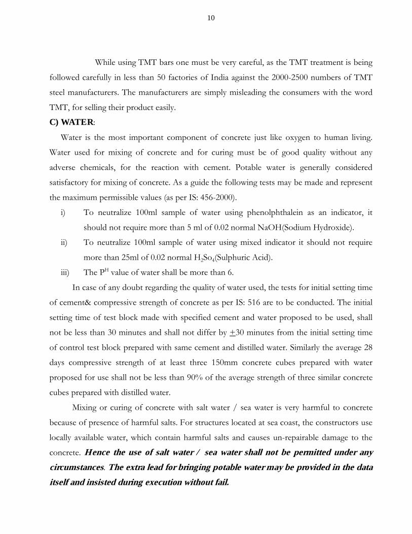
While using TMT bars one must be very careful, as the TMT treatment is being
followed carefully in less than 50 factories of India against the 2000-2500 numbers of TMT
steel manufacturers. The manufacturers are simply misleading the consumers with the word
TMT, for selling their product easily.
C) WATER:
Water is the most important component of concrete just like oxygen to human living.
Water used for mixing of concrete and for curing must be of good quality without any
adverse chemicals, for the reaction with cement. Potable water is generally considered
satisfactory for mixing of concrete. As a guide the following tests may be made and represent
the maximum permissible values (as per IS: 456-2000).
i) To neutralize 100ml sample of water using phenolphthalein as an indicator, it
should not require more than 5 ml of 0.02 normal NaOH(Sodium Hydroxide).
ii) To neutralize 100ml sample of water using mixed indicator it should not require
more than 25ml of 0.02 normal H2So4(Sulphuric Acid).
iii) The PH value of water shall be more than 6.
In case of any doubt regarding the quality of water used, the tests for initial setting time
of cement& compressive strength of concrete as per IS: 516 are to be conducted. The initial
setting time of test block made with specified cement and water proposed to be used, shall
not be less than 30 minutes and shall not differ by +30 minutes from the initial setting time
of control test block prepared with same cement and distilled water. Similarly the average 28
days compressive strength of at least three 150mm concrete cubes prepared with water
proposed for use shall not be less than 90% of the average strength of three similar concrete
cubes prepared with distilled water.
Mixing or curing of concrete with salt water / sea water is very harmful to concrete
because of presence of harmful salts. For structures located at sea coast, the constructors use
locally available water, which contain harmful salts and causes un-repairable damage to the
concrete. Hence the use of salt water / sea water shall not be permitted under any
circumstances. The extra lead for bringing potable water may be provided in the data
itself and insisted during execution without fail.
11
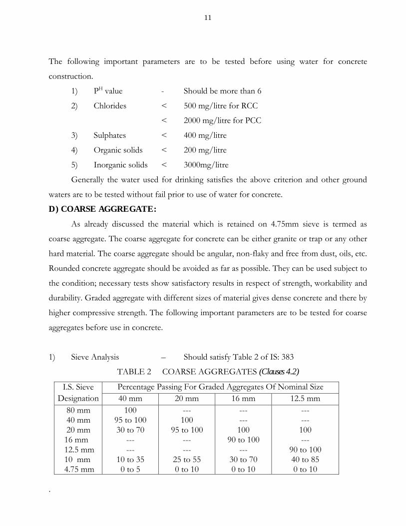
The following important parameters are to be tested before using water for concrete
construction.
1) PH value - Should be more than 6
2) Chlorides < 500 mg/litre for RCC
< 2000 mg/litre for PCC
3) Sulphates < 400 mg/litre
4) Organic solids < 200 mg/litre
5) Inorganic solids < 3000mg/litre
Generally the water used for drinking satisfies the above criterion and other ground
waters are to be tested without fail prior to use of water for concrete.
D) COARSE AGGREGATE:
As already discussed the material which is retained on 4.75mm sieve is termed as
coarse aggregate. The coarse aggregate for concrete can be either granite or trap or any other
hard material. The coarse aggregate should be angular, non-flaky and free from dust, oils, etc.
Rounded concrete aggregate should be avoided as far as possible. They can be used subject to
the condition; necessary tests show satisfactory results in respect of strength, workability and
durability. Graded aggregate with different sizes of material gives dense concrete and there by
higher compressive strength. The following important parameters are to be tested for coarse
aggregates before use in concrete.
1) Sieve Analysis – Should satisfy Table 2 of IS: 383
TABLE 2 COARSE AGGREGATES (Clauses 4.2)
I.S. Sieve Designation
Percentage Passing For Graded Aggregates Of Nominal Size40 mm 20 mm 16 mm 12.5 mm
80 mm 40 mm 20 mm 16 mm 12.5 mm 10 mm 4.75 mm
10095 to 10030 to 70
------
10 to 350 to 5
---100
95 to 100------
25 to 550 to 10
------100
90 to 100---
30 to 700 to 10
------100---
90 to 10040 to 850 to 10
.
12
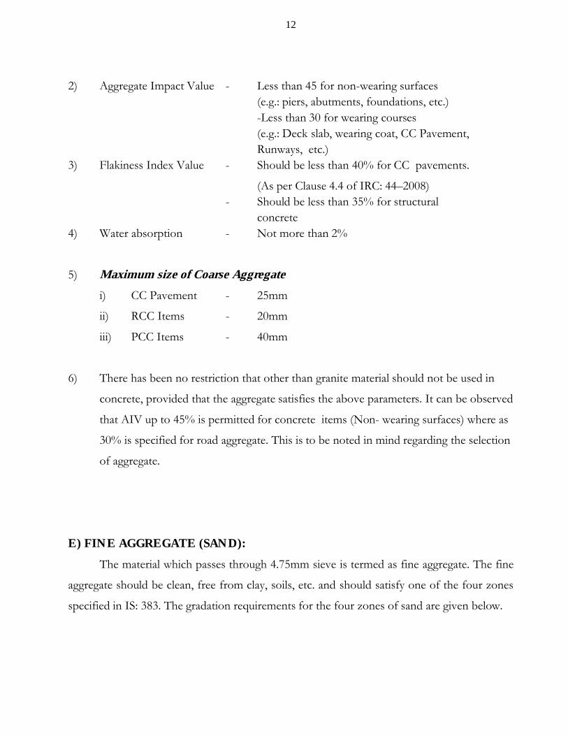
2) Aggregate Impact Value - Less than 45 for non-wearing surfaces (e.g.: piers, abutments, foundations, etc.)-Less than 30 for wearing courses (e.g.: Deck slab, wearing coat, CC Pavement,Runways, etc.)
3) Flakiness Index Value - Should be less than 40% for CC pavements.
(As per Clause 4.4 of IRC: 44–2008)- Should be less than 35% for structural
concrete4) Water absorption - Not more than 2%
5) Maximum size of Coarse Aggregate
i) CC Pavement - 25mm
ii) RCC Items - 20mm
iii) PCC Items - 40mm
6) There has been no restriction that other than granite material should not be used in
concrete, provided that the aggregate satisfies the above parameters. It can be observed
that AIV up to 45% is permitted for concrete items (Non- wearing surfaces) where as
30% is specified for road aggregate. This is to be noted in mind regarding the selection
of aggregate.
E) FINE AGGREGATE (SAND):
The material which passes through 4.75mm sieve is termed as fine aggregate. The fine
aggregate should be clean, free from clay, soils, etc. and should satisfy one of the four zones
specified in IS: 383. The gradation requirements for the four zones of sand are given below.
13
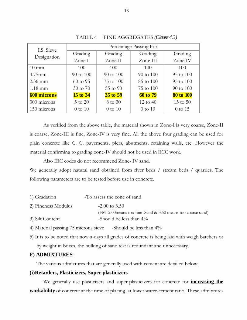
TABLE 4 FINE AGGREGATES (Clause 4.3)
I.S. Sieve Designation
Percentage Passing For GradingZone I
GradingZone II
GradingZone III
GradingZone IV
10 mm4.75mm2.36 mm1.18 mm600 microns300 microns150 microns
10090 to 10060 to 9530 to 7015 to 345 to 200 to 10
10090 to 10075 to 10055 to 9035 to 598 to 300 to 10
10090 to 10085 to 10075 to 10060 to 7912 to 400 to 10
10095 to 10095 to 10090 to 10080 to 10015 to 500 to 15
As verified from the above table, the material shown in Zone-I is very coarse, Zone-II
is coarse, Zone-III is fine, Zone-IV is very fine. All the above four grading can be used for
plain concrete like C. C. pavements, piers, abutments, retaining walls, etc. However the
material confirming to grading zone-IV should not be used in RCC work.
Also IRC codes do not recommend Zone- IV sand.
We generally adopt natural sand obtained from river beds / stream beds / quarries. The
following parameters are to be tested before use in concrete.
1) Gradation -To assess the zone of sand
2) Fineness Modulus -2.00 to 3.50(FM- 2.00means too fine Sand & 3.50 means too coarse sand)
3) Silt Content -Should be less than 4%
4) Material passing 75 microns sieve -Should be less than 4%
5) It is to be noted that now-a-days all grades of concrete is being laid with weigh batchers or
by weight in boxes, the bulking of sand test is redundant and unnecessary.
F) ADMIXTURES:
The various admixtures that are generally used with cement are detailed below:
(i)Retarders, Plasticizers, Super-plasticizers
We generally use plasticizers and super-plasticizers for concrete for increasing the
workability of concrete at the time of placing, at lower water-cement ratio. These admixtures

14
will be useful for good compaction of concrete at low water-cement ratios. These are mixed
with cement, while mixing of concrete at the rates specified below:
a) plasticizers -Up to 1% by mass of cementation materials
b) Super-plasticizers -Up to 2% by mass of cementation materials
ii) Fibers:
Fibers are used in concrete for enhancing the ductility and fatigue life of high grade
concrete. The fibers shall be of steel / polymeric such as polypropylene / Polyester /
Polyethylene / Nylon and shall be uniformly dispersed in concrete mass at the time of
concrete production. The Polymeric fibers may be added in concrete in the dosage of
0.2 – 0.4 percent by mass of cement. The diameter of Polymeric fibers normally varies
from 10 to 70 microns.
In market, presently ‘Recron 3S’ fibers manufactured by Reliance Industries are
available. By adding these fibers, the strength of concrete is increased. Specialist literature may
be referred and test conducted, before using in concrete.
MINERAL ADMIXTURES
The following materials may be added as mineral admixtures.
a) Fly Ash:
Fly ash is the material obtained as by product of thermal power plant. The mixing of
fly ash in concrete increases the strength and workability at low water cement ratio results in
savings in cement content and increase in durability of concrete. IRC: 44-2008 recommends
maximum dosage of 20% by mass of cementations materials. The initial cost of fly ash is zero
and can be taken from Thermal Power Stations at free of cost. The only problem with fly
ash concrete is that it requires continuous curing for 28 days as the gain in strength is
low at early ages, compared to OPC concrete. The strength at 28 days is same for both
concrete mixes.
b) Silica Fume:
The Silica fume (Very fine non crystalline silicon dioxide) is a byproduct of
manufacture of silicon, Ferro-silicon, from quartz and carbon in electric arc furnace. It is

15
generally used in proportion of 5 to 10 percent of cementations material content of the mix.
Use of silica fume is extremely advantageous for higher grades of concrete such as M50Grade
and above and for high performance concrete with special requirement. This is generally used
for long span pre-stressed and precast bridge structures worldwide.
So far, we have discussed about the various materials that are used in concrete
and their properties and requirements for concrete.
3) CEMENT CONCRETE MIX DESIGN
After selecting the various components of concrete, we have to select whether nominal
mix concrete is to be adopted or design mix concrete is to be adopted. For minor and
unimportant works we will adopt nominal mix concrete like (1:4:8), (1:3:6), (1:2:4), (1: 1 ½:3).
The different nominal mix concretes that are generally for some items are given below for
guidance.
S. No.
Mix Proportion
Cement Content per Cum
Item of workEquivalent Grade of Concrete
a) CC (1:4:8) 166 Kg Bed for CC drains &culvert body walls, bed below CC pavements, etc.
--
b) CC (1:3:6) 221 Kg Bed for CC drains & walls of drain, retaining walls, toe walls, culvert body walls, etc.
M10
c) CC (1:2:4) 331 Kg PCC Raft of slab culverts, substructure, RCC columns& beams of buildings, etc.
M15
d) CC (1: 1 ½:3)
441 Kg Deck slabs of slab culverts, RCC Bed blocks & backing walls, CC pavement works of small value (less than Rs. 10.00 Lakhs), RCC slabs& beams of buildings nearer to sea coast (within 25 Km from sea coast), etc.
M20
16
As seen from the above, the cement content shown is as high as 441 Kg/cum for CC
(1:1½:3) which is taken equivalent to M20Grade. It is a fact that maximum cement content
for any grade of concreteuptoM80, as per IS: 456 is only 450 Kg/cum. It can be
concluded that the use of nominal mix concrete is uneconomical and unnecessary for present
day scenario. The grade of M20 can be achieved with a cement content of 350 Kg/cum, by
designing the concrete mix and we can save 91 Kg of cement per cum of concrete.
However, as the design of concrete mix involves a sum of Rs.20,000/- towards
laboratory charges and very good quality control during mixing of concrete. Nominal mix
concrete is being adopted for small works in the range of Rs. 10.00 Lakhs to Rs. 20.00
Lakhs in order to mitigate the problems of small contractors and for speedy execution of
work, even though the cement content is high.
Hence, as far as possible design mix concrete should be adopted for all structural
concrete items.
Now let us see what is the design of concrete mix? The design of concrete mix
means selection of suitable proportions of various components, for arriving at a
specified grade concrete mix duly satisfying the requirements of workability,
compressive strength and durability.
Hence a design mix should have
a) Adequate workability at the time of placing of mix to have good compaction.
b) The required compressive strength at the specified 28 days age.
c) The long lasting durability of concrete structure during its service life (design period).
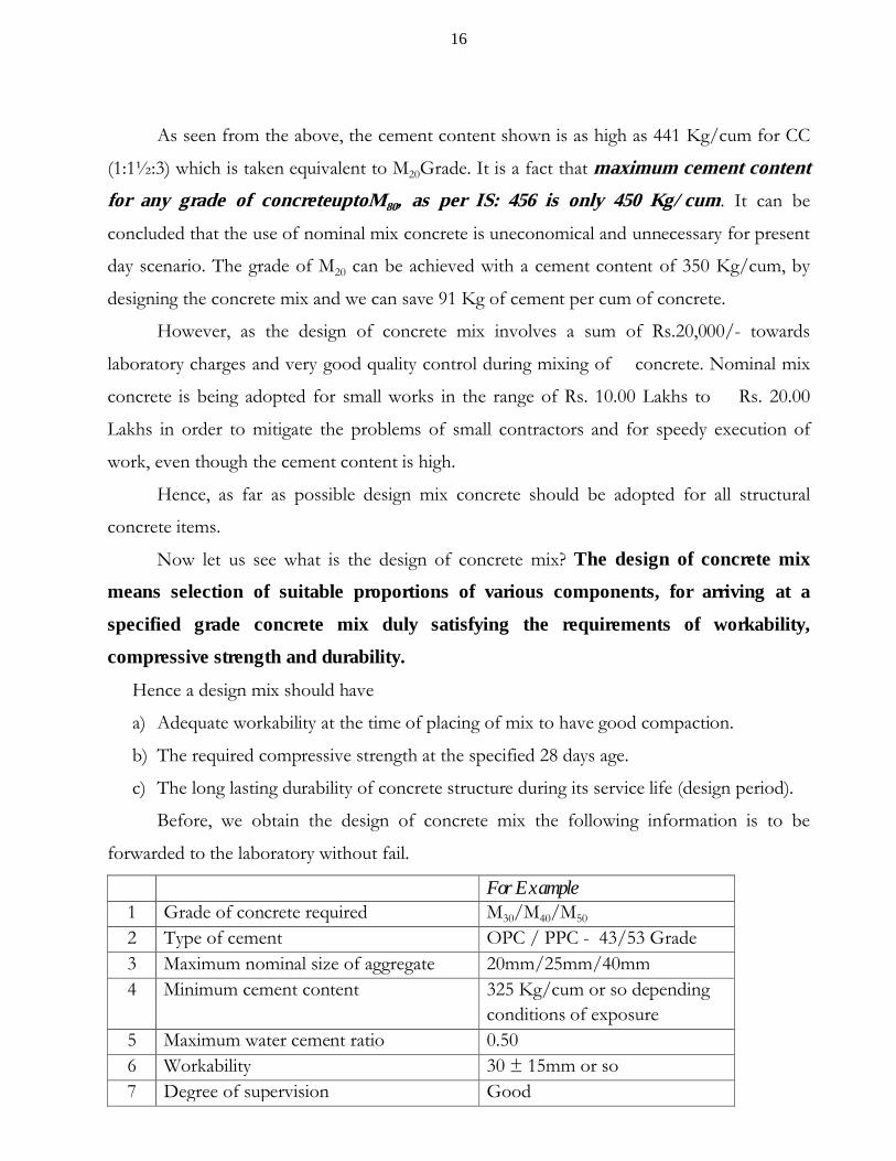
Before, we obtain the design of concrete mix the following information is to be
forwarded to the laboratory without fail.
For Example1 Grade of concrete required M30/M40/M50
2 Type of cement OPC / PPC - 43/53 Grade3 Maximum nominal size of aggregate 20mm/25mm/40mm4 Minimum cement content 325 Kg/cum or so depending
conditions of exposure5 Maximum water cement ratio 0.506 Workability 30 ± 15mm or so7 Degree of supervision Good

17
8 Type of aggregate HBG crushed stone aggregate9 Maximum cement content 425 Kg/cum (or) 450Kg/cum10 Chemical admixture type Super-plasticizer / Plasticizer11 Mineral admixture type Fly ash - 20%
Silica fume – 5% etc.
With the above information, we need to send samples of cement (3 bags), coarse aggregate (5
bags) and fine aggregate (3 bags) to the laboratory duly stating the working condition.
After receiving the above
days for information and sample materials, the laboratory authorities will conduct the
following tests on the materials, for the design of concrete mix.
a) Compressive strength of cement at 28 confirmation of grade of cement.
b) Specific gravity of
(i) Cement (3.15), (ii) Course aggregate (2.74) and (iii) Fine aggregate (2.63).
c) Water absorption of coarse aggregate
(should be less than 2%) and fine aggregate (should be less than 2%).
d) Gradation of coarse aggregate to check the gradation with IS: 383.
e) Gradation of fine aggregate for confirming the grading zone as per IS: 383.
After conducting the above tests, the design of concrete mix will be done as per
relevant IRC code (IRC: 44-2008 for CC pavements) duly finalizing the quantities of cement,
coarse aggregate, fine aggregate and water. After arriving at the selected proportions, trial mix
will be prepared and cubes are casted. The cubes are to be cured for 7 days or 28 days for
assessing the compressive strength of concrete mix designed. As seen from above, a
minimum period of 60 days or more is required for any laboratory for issuing a mix design of
concrete for the specified grade. Hence the field officers must send the requisition along
with samples two months in advance before commencement of work. It is our practice,
to call a mix design 2 to 3 days before the commencement of work which is nothing but
fabricating a false mix design, to start the work, finally making it a ritual for receiving payment
and to avoid complications from inspecting agencies. When a mix design is available for the
same source of all materials and type of cement for a particular grade of concrete, this can be
adopted for another work, subject to the approval of Engineer-in-Charge, provided

18
that the mix design done earlier is not more than one year old (Clause 9.2.3 of IS: 456-
2000).
The above procedure is to be followed for obtaining a mix design from laboratory well
in advance, before commencement of work
4) PROPORTIONING OF MATERIALS BY WEIGHT
After receiving the mix design of concrete from the laboratory, we have to make a trial
mix with the proportion of materials specified and cubes are to be casted. These cubes are to
be tested for 7 days / 28 days for confirmation of mix design. If the compressive strength of
trial cubes casted satisfies the compressive strength required, the mix design can be adopted.
After assessing the compressive strength of trial mix, the arrangements are to be made
for proper mixing of various components of concrete. In case of large works, weigh batching
plants are readily available, suitable setting can be made for receiving the specified quantity of
materials for each batch. It is always advisable to use mobile weigh batchers for concrete.
However in our Department works, we do not have weigh batching plants or weigh batchers
and we have to load the materials in the hopper of the mixer by weight. For this we have to
work out the materials required for each load (say one bag or 50 Kg of cement) and boxes of
suitable sizes (better the volume of box should be equal to volume of one cement bag=28.8
litres) are to be prepared separately for coarse aggregate and fine aggregate and a container for
mixing specified quantity of water.
A typical calculation for working out the sizes of boxes required, based on a laboratory
mix design is given below for convenience of readers.
Mix Design given by the laboratory (Materials required for One Cum of Concrete):
(a) Cement : 416Kg/m3
(b) Water : 158 Kg/m3
(c) Fine aggregate : 668 Kg/m3
(d) Coarse aggregate : 1242 Kg/m3

19
(e) Water -cement ratio : 0.38
(f) Chemical admixture : 2.50 Kg/m3
STEP- 1: As the load of hopper mixer is for one bag of cement, we have to work out the
materials required for 50 Kg of cement from the mix design given for one cum
of concrete.
Cement content = 416 Kg/m3
No. of bags of cement = 416 / 50 = 8.32 bags
STEP- 2: Now we have to calculate the weight of various components of materials for
one bag of cement as detailed below.
a) Water : 158Kg (158 Litres)/ 8.32 Bags= 18.99 Kg (or) 19 Kg = 19.00 Litres
b) Fine aggregate (Sand) : 668.00 / 8.32 = 80.29 Kg
c) Course Aggregate (Chips) : 1242.00 / 8.32 = 149.28 Kg
d) Chemical admixture : 2.50 / 8.32 = 0.30 Kg
STEP- 3: From the above, we can say that one bag of cement, 80.29 Kg of sand, and
149.28 Kg of coarse aggregate are to be loaded in the hopper of concrete mixer.
(i) For water we can take a 10 Litre PVC can and cut to 9.50 litre size. Two cans of
9.50 litres each can be poured for each load of concrete without any difficulty.
In practice, slightly higher water content may be needed, as there will be some
loss of water from centering. This is to be adjusted slightly as per requirement,
at the time of compaction by needle vibrators or pan vibrators.
(ii) For fine aggregate we have to load 80.29 Kg. For this we can take a standard
box of size 0.375m x 0.3m0 x 0.30m (earlier 1.25cft box) and fill the material up
to the top of box without coping in a level manner and weigh the same. (One
box of sand approximately weighs 45 Kg). The weight of sand may be accurately
measured thrice and the average weight is to be considered.
Say the average value of weight of sand in the box = 45.65 Kg.
Weight of sand required for one load = 80.29 Kg.
Number of boxes required =80.29/45.65
= 1.76 No.

20
As it is difficult to load fractions of boxes, it is better to convert them in to 2
boxes of smaller height keeping the area of boxes constant.
The approximate height required for 2 boxes = 0.30 x 1.76 / 2
= 0.264m (0.30m is the height of original box)
Hence provide 2 boxes of 300mm x 375mm x 264mmsize sand for each load of
mix.
Check: Weight of material for two loads
Density of sand = (45.65x1000)/ (37.5x30x30)
= 1.3526 G/cm3
Weight of material for 2 boxes of size 375mmx300mmx264mm
= 2x37.5x30x26.4x1.3526/1000 = 80.34 Kg
Hence O.K
(iii) For coarse aggregate we have to load 149.28 Kg. Similarly, as detailed above for
fine aggregate, the average value of weight of chips in box can be arrived say the
average value of weight of chips in one box is 48.90 Kg.
No. of boxes required for one load = 149.28/48.90 = 3.05 No
We can say 3 boxes (0.375m x 0.30m x 0.30m size)of chips are to be loaded for
each load of one bag of cement. As such, the labour can conveniently load --
i) 1 Bag of cement
ii) 2 Smaller boxes of sand
iii) 3 Standard boxes (375mm x 300mm x 300mm size) of chips
iv) 2 Altered cans (9.50 Litres each) of water
v) Chemical admixture with a small tin weighing 0.30 Kg
The field staff may be trained to load the above quantity of materials, in the hopper of
concrete mixer and the concrete can be laid easily. Please note that it is a tricky method, for our
convenience and not acceptable by many consultants, who insist for weigh batchers only. This is only a
last resort in the absence of weigh batchers.
21
5) WATER-CEMENT RATIO
It is a well-known fact that water is the main component which plays vital role in
achieving the three main parameters of concrete, i.e. Workability, compressive strength and
durability. The selection of water for concrete must be done with due care, as any harmful
salts may lead to total collapse of structure. One must ensure twice regarding the suitability of
water available for concrete as it is generally the opinion of many Engineers, what happen if
water available at site is used even if it is hard water and the factor of safety provided in the
design will take care of all our lapses. It is to be noted that there are many factors which
influence the strength of concrete and we must be very judicious in selecting every
material in concrete.
After selecting the water proposed for use, we have to put our mind on water- cement
ratio. Before going to this, first of all we have to know, how much water is needed for
reaction of cement with water. Researches revealed that 25% water is required for reaction
with cement. That means the minimum water-cement ratio required is 0.25. With this water
cement ratio, we cannot make concrete either workable or to compact the concrete. So we
must slightly increase the water-cement ratio to have desired workability and to compact the
concrete. Practically a concrete with water-cement ratio of 0.35 is the optimum water-cement
ratio to achieve the specified characteristics of concrete. Even the concrete prepared with the
water-cement ratio of 0.35 is observed too stiff and difficult to compact with vibrators, as
time lapses. So, the field engineers and the masons prefer to have loose mix, so that it can be
placed and vibrated easily. For the sake of this small convenience, we sacrifice the strength of
concrete. Let us see how the strength of concrete is reduced with increase in water
cement-ratio. The increase in water-cement ratio leave more voids in concrete after
hardening and effect the strength alarmingly. Hence use minimum water in mixing as nearer
as possible to a water-cement ratio of 0.35. Excess use of water in mixing, cause segregation
of aggregate and if vibrated more the soft cement mortar will come to the top (called laitance)
which appears very smooth and hard aggregate goes down finally leading to the reduction in
strength of concrete.
22
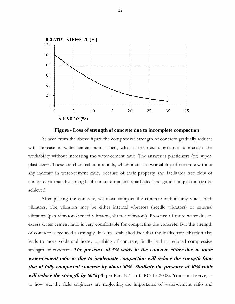
Figure - Loss of strength of concrete due to incomplete compaction
As seen from the above figure the compressive strength of concrete gradually reduces
with increase in water-cement ratio. Then, what is the next alternative to increase the
workability without increasing the water-cement ratio. The answer is plasticizers (or) super-
plasticizers. These are chemical compounds, which increases workability of concrete without
any increase in water-cement ratio, because of their property and facilitates free flow of
concrete, so that the strength of concrete remains unaffected and good compaction can be
achieved.
After placing the concrete, we must compact the concrete without any voids, with
vibrators. The vibrators may be either internal vibrators (needle vibrators) or external
vibrators (pan vibrators/screed vibrators, shutter vibrators). Presence of more water due to
excess water-cement ratio is very comfortable for compacting the concrete. But the strength
of concrete is reduced alarmingly. It is an established fact that the inadequate vibration also
leads to more voids and honey combing of concrete, finally lead to reduced compressive
strength of concrete. The presence of 5% voids in the concrete either due to more
water-cement ratio or due to inadequate compaction will reduce the strength from
that of fully compacted concrete by about 30%. Similarly the presence of 10% voids
will reduce the strength by 60% (As per Para N.1.4 of IRC: 15-2002). You can observe, as
to how we, the field engineers are neglecting the importance of water-cement ratio and
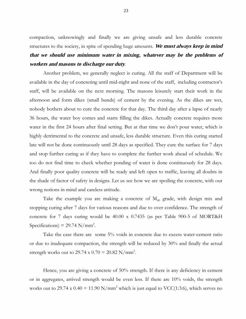
23
compaction, unknowingly and finally we are giving unsafe and less durable concrete
structures to the society, in spite of spending huge amounts. We must always keep in mind
that we should use minimum water in mixing, whatever may be the problems of
workers and masons to discharge our duty.
Another problem, we generally neglect is curing. All the staff of Department will be
available in the day of concreting until mid-night and none of the staff, including contractor’s
staff, will be available on the next morning. The masons leisurely start their work in the
afternoon and form dikes (small bunds) of cement by the evening. As the dikes are wet,
nobody bothers about to cure the concrete for that day. The third day after a lapse of nearly
36 hours, the water boy comes and starts filling the dikes. Actually concrete requires more
water in the first 24 hours after final setting. But at that time we don’t pour water, which is
highly detrimental to the concrete and unsafe, less durable structure. Even this curing started
late will not be done continuously until 28 days as specified. They cure the surface for 7 days
and stop further curing as if they have to complete the further work ahead of schedule. We
too do not find time to check whether ponding of water is done continuously for 28 days.
And finally poor quality concrete will be ready and left open to traffic, leaving all doubts in
the shade of factor of safety in designs. Let us see how we are spoiling the concrete, with our
wrong notions in mind and careless attitude.
Take the example you are making a concrete of M40 grade, with design mix and
stopping curing after 7 days for various reasons and due to over confidence. The strength of
concrete for 7 days curing would be 40.00 x 0.7435 (as per Table 900-5 of MORT&H
Specifications) = 29.74 N/mm2.
Take the case there are some 5% voids in concrete due to excess water-cement ratio
or due to inadequate compaction, the strength will be reduced by 30% and finally the actual
strength works out to 29.74 x 0.70 = 20.82 N/mm2.
Hence, you are giving a concrete of 50% strength. If there is any deficiency in cement
or in aggregates, arrived strength would be even less. If there are 10% voids, the strength
works out to 29.74 x 0.40 = 11.90 N/mm2 which is just equal to VCC(1:3:6), which serves no
24
purpose for any durable structure. This is all due to the negligence in making of concrete, but
not due to the less usage of cement or other materials.
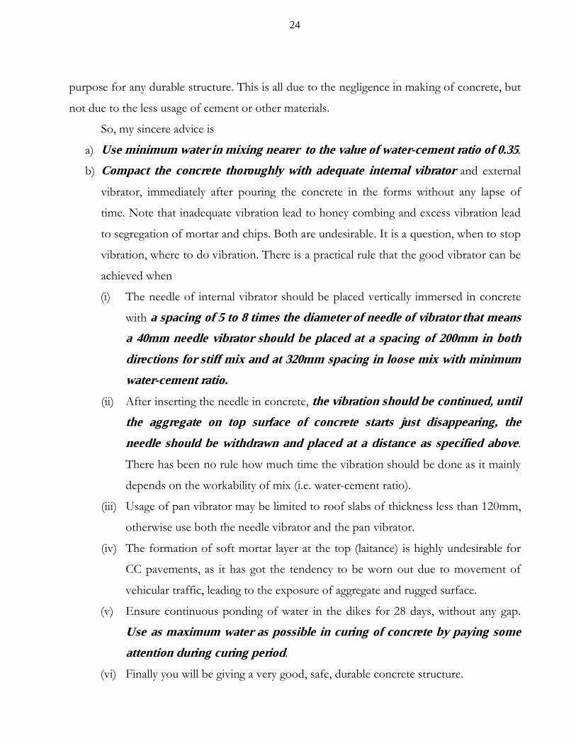
So, my sincere advice is
a) Use minimum water in mixing nearer to the value of water-cement ratio of 0.35.
b) Compact the concrete thoroughly with adequate internal vibrator and external
vibrator, immediately after pouring the concrete in the forms without any lapse of
time. Note that inadequate vibration lead to honey combing and excess vibration lead
to segregation of mortar and chips. Both are undesirable. It is a question, when to stop
vibration, where to do vibration. There is a practical rule that the good vibrator can be
achieved when
(i) The needle of internal vibrator should be placed vertically immersed in concrete
with a spacing of 5 to 8 times the diameter of needle of vibrator that means
a 40mm needle vibrator should be placed at a spacing of 200mm in both
directions for stiff mix and at 320mm spacing in loose mix with minimum
water-cement ratio.
(ii) After inserting the needle in concrete, the vibration should be continued, until
the aggregate on top surface of concrete starts just disappearing, the
needle should be withdrawn and placed at a distance as specified above.
There has been no rule how much time the vibration should be done as it mainly
depends on the workability of mix (i.e. water-cement ratio).
(iii) Usage of pan vibrator may be limited to roof slabs of thickness less than 120mm,
otherwise use both the needle vibrator and the pan vibrator.
(iv) The formation of soft mortar layer at the top (laitance) is highly undesirable for
CC pavements, as it has got the tendency to be worn out due to movement of
vehicular traffic, leading to the exposure of aggregate and rugged surface.
(v) Ensure continuous ponding of water in the dikes for 28 days, without any gap.
Use as maximum water as possible in curing of concrete by paying some
attention during curing period.
(vi) Finally you will be giving a very good, safe, durable concrete structure.

25
c) Don’t waste time to start curing, for the reasons that dikes (small mortar bunds) are not ready. Curing must be started after 12 hours of placing concrete in variably for good quality concrete.
.
6) FABRICATION OF REINFORCEMENT
Before going to the fabrication of reinforcement we have to check the (i) weight per
running meter,(ii) fy value and (iii) percentage elongation of steel, proposed for use for
different diameters. As you don’t have all full length of bars, one must have laps in some bars.
We should have some idea, where the laps are to be provided and how much lap length is to
the provided.
(1) It is to be kept in mind that laps should be preferably not more than 33% of the
total number of rods at a section. In exceptional cases it can be increased to 50%.
(2) The lapping of reinforcement should be avoided in maximum bending moment zone.
For this it is customary not to provide laps in the middle third of total span.
(3) The overlapping length should be as specified in relevant codes.
For Buildings (As per Clause 26.2.5.1ofIS: 456 –2000):
(a) Bars in compression like columns, top rods of beam, etc. : 50 d
(b) Bars in tension like bottom rods in beams : 70 d
The above values are given conservatively as calculated by the formula given in
the Clause 26.2.1. The above lap lengths are safe for any type of condition of stress
at the point of lap. The field engineers with interest can slightly reduce them, by
going through the actual design stresses and bond stresses and calculating the lap
length by the formula given in Clause 26.2.1 of IS 456-2000.
26
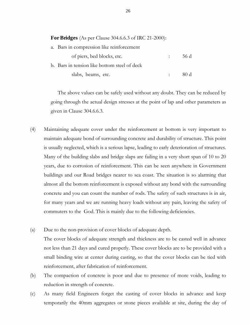
For Bridges (As per Clause 304.6.6.3 of IRC 21-2000):
a. Bars in compression like reinforcement
of piers, bed blocks, etc. : 56 d
b. Bars in tension like bottom steel of deck
slabs, beams, etc. : 80 d
The above values can be safely used without any doubt. They can be reduced by
going through the actual design stresses at the point of lap and other parameters as
given in Clause 304.6.6.3.
(4) Maintaining adequate cover under the reinforcement at bottom is very important to
maintain adequate bond of surrounding concrete and durability of structure. This point
is usually neglected, which is a serious lapse, leading to early deterioration of structures.
Many of the building slabs and bridge slaps are failing in a very short span of 10 to 20
years, due to corrosion of reinforcement. This can be seen anywhere in Government
buildings and our Road bridges nearer to sea coast. The situation is so alarming that
almost all the bottom reinforcement is exposed without any bond with the surrounding
concrete and you can count the number of rods. The safety of such structures is in air,
for many years and we are running heavy loads without any pain, leaving the safety of
commuters to the God. This is mainly due to the following deficiencies.
(a) Due to the non-provision of cover blocks of adequate depth.
The cover blocks of adequate strength and thickness are to be casted well in advance
not less than 21 days and cured properly. These cover blocks are to be provided with a
small binding wire at center during casting, so that the cover blocks can be tied with
reinforcement, after fabrication of reinforcement.
(b) The compaction of concrete is poor and due to presence of more voids, leading to
reduction in strength of concrete.
(c) As many field Engineers forget the casting of cover blocks in advance and keep
temporarily the 40mm aggregates or stone pieces available at site, during the day of
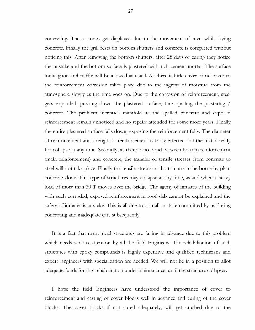
27
concreting. These stones get displaced due to the movement of men while laying
concrete. Finally the grill rests on bottom shutters and concrete is completed without
noticing this. After removing the bottom shutters, after 28 days of curing they notice
the mistake and the bottom surface is plastered with rich cement mortar. The surface
looks good and traffic will be allowed as usual. As there is little cover or no cover to
the reinforcement corrosion takes place due to the ingress of moisture from the
atmosphere slowly as the time goes on. Due to the corrosion of reinforcement, steel
gets expanded, pushing down the plastered surface, thus spalling the plastering /
concrete. The problem increases manifold as the spalled concrete and exposed
reinforcement remain unnoticed and no repairs attended for some more years. Finally
the entire plastered surface falls down, exposing the reinforcement fully. The diameter
of reinforcement and strength of reinforcement is badly effected and the mat is ready
for collapse at any time. Secondly, as there is no bond between bottom reinforcement
(main reinforcement) and concrete, the transfer of tensile stresses from concrete to
steel will not take place. Finally the tensile stresses at bottom are to be borne by plain
concrete alone. This type of structures may collapse at any time, as and when a heavy
load of more than 30 T moves over the bridge. The agony of inmates of the building
with such corroded, exposed reinforcement in roof slab cannot be explained and the
safety of inmates is at stake. This is all due to a small mistake committed by us during
concreting and inadequate care subsequently.
It is a fact that many road structures are failing in advance due to this problem
which needs serious attention by all the field Engineers. The rehabilitation of such
structures with epoxy compounds is highly expensive and qualified technicians and
expert Engineers with specialization are needed. We will not be in a position to allot
adequate funds for this rehabilitation under maintenance, until the structure collapses.
I hope the field Engineers have understood the importance of cover to
reinforcement and casting of cover blocks well in advance and curing of the cover
blocks. The cover blocks if not cured adequately, will get crushed due to the
28
movement of men, during concreting operation and serve no purpose. So, please be
careful regarding cover to reinforcement during concreting operation.
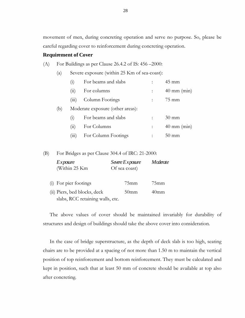
Requirement of Cover
(A) For Buildings as per Clause 26.4.2 of IS: 456 –2000:
(a) Severe exposure (within 25 Km of sea-coast):
(i) For beams and slabs : 45 mm
(ii) For columns : 40 mm (min)
(iii) Column Footings : 75 mm
(b) Moderate exposure (other areas):
(i) For beams and slabs : 30 mm
(ii) For Columns : 40 mm (min)
(iii) For Column Footings : 50 mm
(B) For Bridges as per Clause 304.4 of IRC: 21-2000:
Exposure Severe Exposure Moderate(Within 25 Km Of sea coast)
(i) For pier footings 75mm 75mm
(ii) Piers, bed blocks, deck 50mm 40mmslabs, RCC retaining walls, etc.
The above values of cover should be maintained invariably for durability of
structures and design of buildings should take the above cover into consideration.
In the case of bridge superstructure, as the depth of deck slab is too high, seating
chairs are to be provided at a spacing of not more than 1.50 m to maintain the vertical
position of top reinforcement and bottom reinforcement. They must be calculated and
kept in position, such that at least 50 mm of concrete should be available at top also
after concreting.
29
In case of cantilever projection of slab of T-beam structure, voided deck slab, the
main reinforcement should be kept at the top in cantilever portion. The bar benders
keep the rods at the top. But as men moves over the reinforcement during concreting
operation they will not stay in top position and of left unnoticed, cracks will be
develop at the top. As the thickness is just 100 mm at the end of cantilever, small
rectangular chairs may be provided at the end to keep the top rods in position. This is
to be ensured without fail.
In case of buildings for sun shades, slab projection, this is to be ensured by keeping
necessary concrete cover blocks, so that the main reinforcement remains at the top
during concreting operation. Otherwise the cantilever projections fail. We can see in
many buildings, the steel for cantilever projections at the bottom due to the above
problem.
(5) Fixing of rainwater down take pipes, drainage spouts, reinforcement for hand
rails and hand posts, mastic pads at expansion joints is to be checked regarding
the spacing and position before starting concrete.
(6) Fixing of Kraft paper for bridges, bearing plastering with Kraft paper over load
bearing walls of buildings is to be ensured without fail.
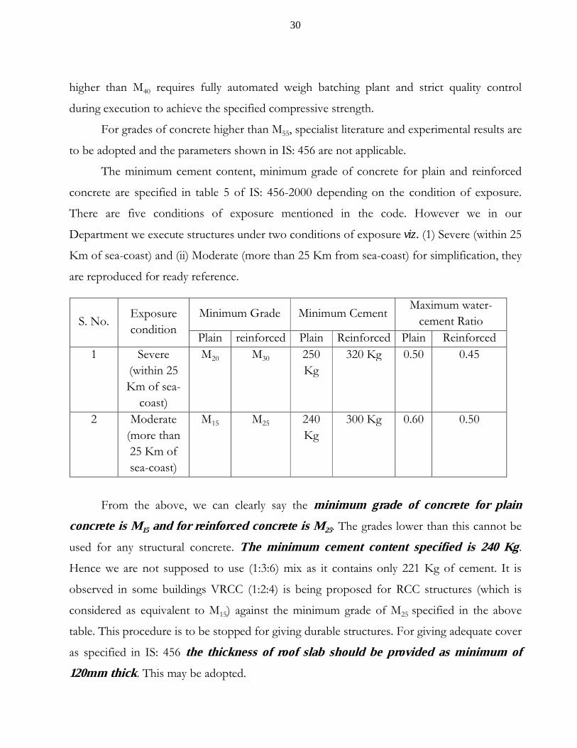
7) IFFERENT GRADES OF CONCRETE
IS: 456-2000, Classifies different grades of concrete according to their usage in Clause
6.1 (Table 2)
a) Ordinary Concrete : M10, M15, M20
b) Standard Concrete : M25, M30, M35, M40, M45, M50, M55
c) High Strength concrete : M60, M65, M70, M75, M80
The mixes under ordinary concrete M10, M15and M20 are generally nominal mix
concrete. However, design mix concrete is economical and can be used from M15 grade
onwards. In our Department we adopt concrete grades up to M40. The grades of concrete
30
higher than M40 requires fully automated weigh batching plant and strict quality control
during execution to achieve the specified compressive strength.
For grades of concrete higher than M55, specialist literature and experimental results are
to be adopted and the parameters shown in IS: 456 are not applicable.
The minimum cement content, minimum grade of concrete for plain and reinforced
concrete are specified in table 5 of IS: 456-2000 depending on the condition of exposure.
There are five conditions of exposure mentioned in the code. However we in our
Department we execute structures under two conditions of exposure viz. (1) Severe (within 25
Km of sea-coast) and (ii) Moderate (more than 25 Km from sea-coast) for simplification, they
are reproduced for ready reference.
From the above, we can clearly say the minimum grade of concrete for plain
concrete is M15 and for reinforced concrete is M25. The grades lower than this cannot be
used for any structural concrete. The minimum cement content specified is 240 Kg.
Hence we are not supposed to use (1:3:6) mix as it contains only 221 Kg of cement. It is
observed in some buildings VRCC (1:2:4) is being proposed for RCC structures (which is
considered as equivalent to M15) against the minimum grade of M25 specified in the above
table. This procedure is to be stopped for giving durable structures. For giving adequate cover
as specified in IS: 456 the thickness of roof slab should be provided as minimum of
120mm thick. This may be adopted.
S. No.Exposurecondition
Minimum Grade Minimum CementMaximum water-
cement RatioPlain reinforced Plain Reinforced Plain Reinforced
1 Severe (within 25 Km of sea-
coast)
M20 M30 250 Kg
320 Kg 0.50 0.45
2 Moderate (more than 25 Km of sea-coast)
M15 M25 240 Kg
300 Kg 0.60 0.50

31
Further the cement content is to be slightly adjusted depending on the size of
aggregate. The values of minimum cement content given in the above table are for 20 mm
aggregate. The cement content will be more for lower size aggregate and less for larger size
aggregate. If we use 10 mm aggregate instead of 20 mm aggregate the cement content should
be increased by 40 Kg per cum. Similarly if we use 40 mm aggregate the cement content can
be reduced by 30 Kg per cum. It is to be kept in mind that when there is heavy congestion of
reinforcement, as in the case of bulb portion of the web of T-beam bridges usage of 20 mm
aggregate may lead to severe gaps and concrete not flow down, due to large depth and small
width of beam. In some cases the bottom steel was not surrounded by any concrete due to
congestion and finally leading to collapse of structures. In such cases, it is advisable to adopt
10 mm size aggregate with increased cement content, so that the concrete can flow down to
bottom of beam and honey combs can be avoided.
8) REPARATION OF FORM WORK
Generally, it is felt that preparation of form work is not the duty of field Engineer and
is left to the discretion of bar benders. Even though, it is the responsibility of centering staff,
the field officers must check the following items to ensure the safety of form work and to
avoid loss of mortar, to avoid bulging of shutters during vibration. To have an idea, the
following points are listed below.
1) Ensure that the steel cribs are supported on stable hard soil. If the soil is loose, it is
advisable to lay concrete bed 150 mm thick and keep the steel cribs over it.
2) Ensure that the spacing of cribs is adequate. Generally the spacing of cribs at 1.50 m
c/c is satisfactory.
3) All the cribs are braced with the steel rods at a vertical spacing of 0.60 m in both
directions.
4) In case of sands, it is better to soak the sand completely in water before erecting cribs.
No loose soil shall be filled for adjusting the heights to suit the height of cribs. Extra
width may be provided on all sides of cribs, to provide lateral support and to avoid
slipping of sand due to rains, etc.
32
5) The channels placed over the cribs for placing centering sheets are to be properly
spaced. Adequate lap length may be provided when the length of channel is less than
span length without fail. Bend shutters and shutters with holes are to be discouraged
for form work.
6) The joints of centering sheets are to be sealed to avoid loss of slurry during concreting
and vibrating operation. An adhesive tape (brown colour used for books& packing) 2”
wide can be used conveniently for sealing the joints of shutters. In case of sloped joints
or vertical joints, cotton waste obtained from hand looms can be inserted without gap.
A rubber seal also may be used in this way to avoid loss of slurry.
7) Suitable raise at the center of span may be provided to accommodate the deflection
due to loads as per IRC standard drawings for bridges.
8) All the holes, small gaps left over openings are to be sealed thoroughly before placing
reinforcement.
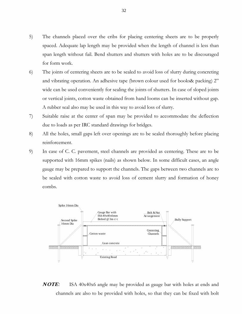
9) In case of C. C. pavement, steel channels are provided as centering. These are to be
supported with 16mm spikes (nails) as shown below. In some difficult cases, an angle
gauge may be prepared to support the channels. The gaps between two channels are to
be sealed with cotton waste to avoid loss of cement slurry and formation of honey
combs.
Second Spike16mm Dia
Spike 16mm Dia
Gauge Bar withISA 40x40x6mmBolted @ 3m c/c
Cotton waste
Bully Support
Bolt & NutArrangement
CenteringChannels
Lean concrete
Existing Road
NOTE: ISA 40x40x6 angle may be provided as gauge bar with holes at ends and
channels are also to be provided with holes, so that they can be fixed with bolt

33
and nuts to avoid bulging of channels. These angles are fixed at 0.50 m from the
end of panel on both sides and one number at center of panel so that the
channels can remain in position, during laying and compaction of concrete. This
method will be very use full when the spikes cannot remain vertically due to
poor soils or when it is not possible to drive spikes like laying of C.C pavement
over a causeway work at more heights. This is tried and proved successful in
some works.
10) Diesel oil or Lubricant oil is to be coated to centering sheets, sides and vertical shutters
to avoid adhesion of concrete with the steel shutters. If this is not done, the surface of
concrete will be rugged and shabby. The same procedure may be adopted for channel
faces in case of CC pavements.
11) The gradient if any required for bridges is to be checked by thin twine, so that
undulations can be rectified before placing reinforcement. All the above mentioned
points are to be attended before placing reinforcement and no item can be attended
once the reinforcement is placed.
12) Adequate number of cover blocks of required thickness, as specified are to be casted,
well in advance and cured properly by the time, the reinforcement is placed over
centering. The size preferably should be 50x50x40 mm for bridges. The thickness of
cover blocks may be increased or decreased as per codal requirements, described
earlier.
13) Bearings if any either Kraft paper bearing or elastomeric bearings are to be fixed and
protected before placing reinforcement.
14) Mastic pads can be placed at joints of deck slab, just before concreting and are to be
readily available of suitable depth as required.
15) The maximum and minimum spacing of reinforcement for RCC as per IS: 456
As per Clause 26.3.3, the maximum spacing between the reinforcing bars shall
not exceed the following values.
a) Beams - main reinforcement : 125 mm
b) Beams - shear reinforcement : 0.75 d (Vertical stirrups) where d = effective depth
34
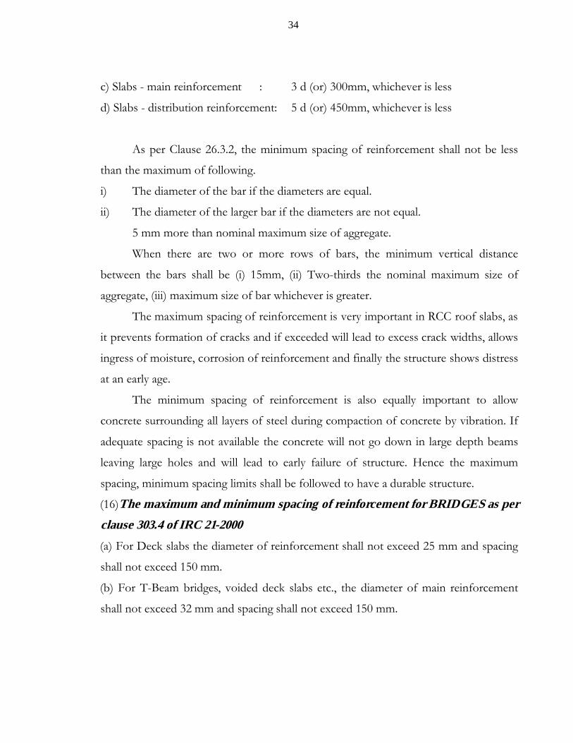
c) Slabs - main reinforcement : 3 d (or) 300mm, whichever is less
d) Slabs - distribution reinforcement: 5 d (or) 450mm, whichever is less
As per Clause 26.3.2, the minimum spacing of reinforcement shall not be less
than the maximum of following.
i) The diameter of the bar if the diameters are equal.
ii) The diameter of the larger bar if the diameters are not equal.
5 mm more than nominal maximum size of aggregate.
When there are two or more rows of bars, the minimum vertical distance
between the bars shall be (i) 15mm, (ii) Two-thirds the nominal maximum size of
aggregate, (iii) maximum size of bar whichever is greater.
The maximum spacing of reinforcement is very important in RCC roof slabs, as
it prevents formation of cracks and if exceeded will lead to excess crack widths, allows
ingress of moisture, corrosion of reinforcement and finally the structure shows distress
at an early age.
The minimum spacing of reinforcement is also equally important to allow
concrete surrounding all layers of steel during compaction of concrete by vibration. If
adequate spacing is not available the concrete will not go down in large depth beams
leaving large holes and will lead to early failure of structure. Hence the maximum
spacing, minimum spacing limits shall be followed to have a durable structure.
(16)The maximum and minimum spacing of reinforcement for BRIDGES as per
clause 303.4 of IRC 21-2000
(a) For Deck slabs the diameter of reinforcement shall not exceed 25 mm and spacing
shall not exceed 150 mm.
(b) For T-Beam bridges, voided deck slabs etc., the diameter of main reinforcement
shall not exceed 32 mm and spacing shall not exceed 150 mm.

35
9) PREPARATION OF CONCRETE
After placing the reinforcement in position, the field engineer must check the
reinforcement for their size, spacing, cover to reinforcement, measurements of beams, slabs,
position of drainage spouts, etc., as per drawing. This must be checked one day in advance,
before starting concrete. Adequate number of internal vibrators (needle vibrators) and
external vibrators (screed vibrators or pan vibrators) are to be kept ready in good working
condition. The boxes prepared as per mix design shall be marked with paint, the type of
material to be loaded. It is the usual practice to pour 50% of water required in mixer drum
first. Then the materials will be loaded in the hopper, as per the mix design. Care may be
taken not to place cement first in hopper. These materials in hopper will be loaded in the
mixer drum and the balance 50% water will be poured slowly. The mixing shall be continued
until uniform mixing of concrete is obtained. As per Clause 10.3.1 of IS: 456-2000, the mixing
time shall be at least2 minutes. Hence a minimum time of 3 to 5 minutes after all the
materials are loaded into the mixture will be purposeful to have a uniform concrete,
depending on the water-cement ratio adopted. After the mixing is completed the concrete
shall be unloaded. The workability of a mix can be assessed by slump cone test. An
experienced Engineer can judge it with eye depending on the stack of concrete unloaded. If it
is firm and high, the mix is having less water-cement ratio and if the stack flows into a
loose concrete, it means high water-cement ratio. Depending on the requirement, we can
slightly modify the water cement-ratio and next loads will be taken up. (The procedure of
conducting slump test for assessing the workability of concrete is enclosed at the end).
After the concrete is unloaded, it has to be carried by wheel borrows or trolleys
depending on the load while lifting the aggregate, it is to be ensured that each part of concrete
contains uniform mix with adequate mortar and aggregates, without any segregation of
concrete material. The concrete material now has to be deposited in the form work manually.
While depositing the concrete, the concrete cannot be dumped from height, as in the case of
foundations, where the concrete is thrown from ground level to foundation. It is to be
stopped, as it leads to segregation. The persons must go nearer to the form work in

36
foundation and drop the concrete carefully. As per Clause13.2 of IS: 456-2000, the maximum
permissible free fall of concrete is 1.50 m. Care should be taken to avoid displacement of steel
reinforcement, while dropping / placing of concrete.
The concrete must be deposited in layers not exceeding 300 mm for internal vibrators
(needle vibrators) and 150 mm for external vibrators. Use of both vibrators will be more
advantageous for compaction of concrete. The process of mixing transporting, placing and
compaction of concrete should be completed within 30 minutes. As already explained over
vibration and under vibration of concrete are harmful and should be avoided.
The detrimental effects of over vibration are detailed below.
i) It segregates the material, bringing the soft material of concrete i.e. mortar to the
top and aggregate to the bottom, so that the top layer is soft and non-uniform.
Finally this causes reduction in compressive strength.
ii) The concrete surrounding reinforcement at top will be too soft and can be carried
away by the vehicular traffic, leading to undesired rugged surface in case of C. C.
Pavements.
Similarly under vibrated concrete is more detrimental, as the concrete may not go
down to the bottom of beam if not compacted properly, leaving large holes and leaving the
bottom layer of steel unconnected with concrete. This happens in deep beams of bridges.
One must ensure adequate compaction of concrete such that the concrete is filled as a solid
mass without voids.
A good compaction and less water-cement ratio are the key factors for the life of any
concrete structure. Hence, compaction of concrete must be done under the guidance and
close supervision of experience Engineers and cannot be left over as a mason’s job. After
compacting the concrete adequately with internal vibrators, the pan vibrator may be used at
the top to level the surface. It does not mean all the finishing operation should be done with
37
pan vibrator. Skilled masons shall be employed, to level the surface of concrete and for
making up the small undulations.
Remember that concrete can be molded to any shape or finish like clay in the hands of
a pot maker. If you have the command and concept of concrete preparation never use water
for making the top surface level or for smooth finish as it spoils concrete.
In case of CC pavement, the laitance (a thin layer of cement mortar formed at the top)
due to vibration is to be cleared with straight trowel, until the coarse aggregate is just touched
with trowel. The presence of laitance on top is likely to be carried away by the vehicular
traffic due to non-presence of aggregate at top. This should be ensured on CC pavement and
all soft cement mortar at top is to be cleared to have a long life durable cement concrete
pavement.
10) UNDER WATER CONCRETING
In some cases, as in the foundation of bridges, water will be present beyond 3 to 4 m
depth depending on season. In rainy season, water may be present at shallow depth of 1.50
m, in sandy soils of coastal district. We are not supposed to lay concrete in water directly. The
alternative is to dewater the foundation with pumps. It is easy to remove the water by using
pumps and place the concrete. This is practicable when the permeability of soil is low and the
seepage of water is low and the concreting operation can be completed before substantial
water is entered in foundations. In case of sandy soils it is highly difficult to control seepage
of water even if you employ many pumps. In order to prevent seepage water getting mixed
with concrete, a small depth trench with a width of 1.0 m and 1.0 m depth will be excavated
all-round the foundations. The seepage water entering from four sides will be collected in the
trenches excavated and from there the water can be pumped by using adequate number of
pumps. The dewatering can be done slowly, so that the water level in trench is lower than the
foundation level and the concrete can be laid, at foundation level. However, when the
foundation concrete quantity is high, that it may take 10 to 12 hours for laying concrete
38
manually, we have to go for alternative arrangements. Once if the water level touches the
foundation level the dewatering cannot be allowed, as it sucks the cement from concrete and
is highly detrimental to concrete. In such cases, we have to use a tremie pipe for laying
concrete which avoids direct contact of concrete with water or skip boxes can be used. The
tremie pipe is nothing but a large diameter PVC pipe of 450 mm diameter with a
funnel at the top. The length of pipe shall be such that the bottom of pipe touches the
foundation level and top of the funnel at ground level. The funnel of tremie pipe is fixed such
that the concrete unloaded from mixer fall into the funnel and flows down through the pipe
to the foundation level. Then the tremie pipe is slightly raised and next load of concrete is
released. This process is continued until all area of foundation is filled with concrete, by
slightly moving the end of PVC pipe through the area of foundation. Vibration should not
be resorted under any condition when concrete is laid in water. We have to use 10%
extra cement over the requirement for underwater concrete.
If a grabbing machine is available which is generally used for sinking of well
foundations it is convenient to lay concrete, with the buckets of machine and taking the
buckets to the bottom of foundation and opening the buckets at that location. In both the
cases, concrete will come into contact with water partially which is inevitable. As the concrete
will be totally under water, after laying the segregated material of concrete if any will get
deposited layer by layer in the closed form work
Note that no dewatering shall be allowed within 24 hours after laying of
concrete. As the concrete is totally under water, the required strength will be achieved
without much difficulty. The above methods proved to be effective in many bridge works
and can be followed without any hesitation.
In case of open foundation, it is suggested not to do dewatering while the concrete is
in progress. However the concrete may be stopped from one end and partial removal of
water by other means manually or low power pumps may be employed, subject to the
condition that the water pumped out should not contain any cement. The operation should
be carried out in such a way the dewatering will not suck the cement from the concrete laid.

39
This is to done in close supervision of experienced Engineers as it is highly dangerous if
cement goes out. Even it will be better to lay the concrete in stagnated water of shallow
depths, than dewatering while concrete is in progress. The process of dewatering when
concrete work is in progress is to be avoided as far as possible.
HOT WEATHER CONCRETING[As per IS: 7861 (Part I) – 1975]
Many of us do not know the effects of high temperatures during laying of concrete.
The high atmospheric temperatures result in rapid hydration of cement, increased
evaporation of mixing water, greater mixing water demand and large volume changes
resulting in cracks. First of all we have to define hot weather concreting. As per IS: 7861, it is
defined as the operation of concreting done at atmospheric temperatures above 400C,
any operation of concreting, where the temperature of concrete at the time of its placement is
expected to be beyond 400C. The MORT&H specification Clause 602.7.2 has given even
stringent limitation that no concreting shall be done, when the concrete temperature is above
300C.
The effects of hot weather concrete can be as listed below.
1) Accelerated setting: High temperature increases the rate of setting of the concrete.
Therefore the duration of time during which the concrete can be handled is reduced.
2) Reduction in strength: High temperature results in increase of the quantity of mixing
water to maintain the workability with consequent reduction in strength.
3) Increased tendency to crack either before or after hardening, plastic shrinkage
cracks may form due to rapid evaporation of water. Cracks may be developed in
hardened concrete either by increased drying shrinkage, resulting from greater mixing
water used or by cooling of the concrete from high temperatures.
4) Rapid evaporation of water during curing period. It is very difficult to retain
moisture for hydration in hot summer and maintain reasonably uniform temperature
conditions during the curing period.

40
Now the problem is how to reduce the temperature of concrete during preparation and
keep it less than 300C as specified. The following are the some of the methods useful for
controlling temperature of concrete.
i) Sprinkling of cold water over coarse aggregate stock piles and keeping them moist.
ii) Reducing the temperature of mixing water by adding crushed ice. It is proved that a
20C reduction in temperature of water reduces 0.50C change in the concrete
temperature. In this case, you have to count the quantity of ice in water-cement
ratio. Use of ice as part of mixing water is highly effective in reducing concrete
temperature, since on melting alone, it takes up heat at the rate of 80 KCal/kg. In
this method one must observe that the ice mixed in water should be melted by the
time mixing of concrete is completed. Otherwise, there is a possibility of ice melting
after consolidation of concrete and thus leaving hollow pockets in concrete, which
causes serious damage to concrete compressive strength.
As per the Figure 2 given in IS: 786 when the ambient temperature is 400C, if 10 Kg of
ice is added in water duly replacing water, the temperature of concrete will be reduced by 20C.
Similarly by increasing the ice quantity, sprinkling of water over aggregate, the temperature of
concrete can be reduced to 300C to avoid detrimental effect of high temperature.
Curing is also very crucial for concrete laid in hot weather, since hot weather leads to
rapid drying of concrete. Immediately, after consolidation and surface drying of concrete shall
be protected from evaporation of moisture by means of wet gunny bags (not dipping). Once
the concrete has attained some degree of hardening sufficient to withstand surface damage
(approximately 12 hours after mixing) moist curing with water shall commence. It is very
important to note that continuous curing is essential, because volume changes due to
alternate wetting and drying, promote the development of surface cracking.
The compressive strength of concrete will also be effected due to high temperature
concrete mixed, placed and cured at high temperatures normally develop higher early
strength. But the compressive strength at 28 days is lower. It is a fact that the 28 days

41
compressive strength of M35 grade concrete cured at 300C will have a strength reduction of
10% to 15% when the same concrete is cured at 400C.
This phenomenon is very important, as we lay CC pavements in dry months of April
to June, when the atmosphere temperatures are above 400C. But we never take any of the
precautions specified above while concreting is in progress. This will definitely land us in
troubles. Hence all of us must be more careful while laying CC pavements in hot weather.
The delay in starting of curing nearly after 48 hours of laying of concrete will cause
irreparable loss in strength of concrete. The requirement of water is very high in the first 24
hours and during that period we provide little curing or no curing, because of which the
strength will be badly affected. We must start the curing after 12 hours in hot seasons
compulsorily. The strength of concrete after 48 hours is 41% as per Table 900-5 of
MORT&H specifications. if you do not provide required water for curing, the compressive
strength of concrete will be alarmingly low. One must be more careful in curing especially for
CC pavements laid in hot weather to avoid complications at a later date.

42
11) SUMMARY OF QUALITY CONTROL TESTS
REQUIRED FOR BRIDGES
A) MATERIALS:
S. No.Name of material
Type of Test Frequency Permissible limits
1 CEMENT a) Fineness of Cement One test for each
consignment
<10%
b) Initial setting time One test for each
consignment
Not less than 30 minutes
c) Final setting time One test for each
consignment
Not more than 600 minutes
d)Compressivestrength at 28 days
i) OPC 33 Gradeii) OPC 43 Gradeiii) OPC 53 Grade
One test for each
consignment > 33 N/mm2
> 43 N/mm2
> 53 N/mm2
2 STEEL a) Weight per runningmeter in Kg
One test for each
consignment
6mm-0.222Kg/m
8mm-0.395Kg/m
10mm-0.620Kg/m
12mm-0.888Kg/m
16mm-1.578Kg/m
20mm-2.465Kg/m
25mm-3.852Kg/m
32mm-6.311Kg/m

43
b) Characteristic yieldstress ‘fy’i) S-240(Mild)ii) S-415 (HYSD)iii) S-500 (TMT)
One test for each
consignment > 240 N/mm2
> 415 N/mm2
> 500 N/mm2
c)Percentage elongation
One test for each
consignment
Not Less than14.5%
3 WATER a) PH Value One test for each source (or) monthly
>6
b) Sulphates One test for each source (or) monthly
< 400 mg/Litre
c) Chlorides One test for each source (or) monthly
< 500 mg/Litre for RCC < 2000 mg/Litre for PCC
4 COARSE AGGREG
ATE
a) Sieve Analysis 1 Test/15m3 As per IS: 383 Tableb) AIV
i) Non-wearing surfaces ii) Wearing surfaces
One test for each source (or) as and
when required (or) monthly
< 45%< 30%
c) FIVi) For Structuresii) For CC pavements
1 Test/30m3
< 35% < 40% (IRC: 44)
d) Water absorption 1 Test/Day < 2%
5 FINE AGGREG
ATE
a) Sieve analysis 1 Test/15 m3 As per IS 383b) Fineness Modulus 1 Test/15 m3 2 to 3.50c) Silt Content 2 Tests/Day < 4%d) Bulking of sand 2 Tests/Day Not required when concrete
is laid by weighte) Water absorption 2 Tests/Day < 2%
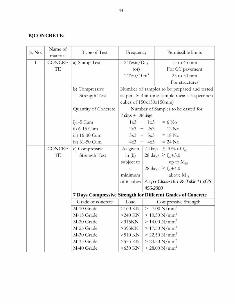
44
B)CONCRETE:
S. No.Name of material
Type of Test Frequency Permissible limits
1 CONCRETE
a) Slump Test 2 Tests/Day (or)
1 Test/10m3
15 to 45 mm For CC pavement
25 to 50 mm For structures
b) Compressive Strength Test
Number of samples to be prepared and tested as per IS: 456 (one sample means 3 specimen cubes of 150x150x150mm)
Quantity of Concrete
i)1-5 Cumii) 6-15 Cumiii) 16-30 Cumiv) 31-50 Cum
Number of Samples to be casted for7 days + 28 days 1x3 + 1x3 = 6 No 2x3 + 2x3 = 12 No 3x3 + 3x3 = 18 No 4x3 + 4x3 = 24 No
CONCRETE
c) Compressive Strength Test
As given in (b)
subject to a
minimum of 6 cubes
7 Days ≥ 70% of fck
28 days ≥ fck+3.0 up to M15
28 days ≥ fck+4.0 above M15
As per Clause 16.1 & Table 11 of IS: 456-2000
7 Days Compressive Strength for Different Grades of Concrete Grade of concrete Load Compressive Strength
M-10 GradeM-15 GradeM-20 GradeM-25 GradeM-30 GradeM-35 GradeM-40 Grade
>160 KN >240 KN>315KN>395KN>510 KN>555 KN>630 KN
> 7.00 N/mm2
> 10.50 N/mm2
> 14.00 N/mm2
> 17.50 N/mm2
> 22.50 N/mm2
> 24.50 N/mm2
> 28.00 N/mm2

45
28 Days Compressive Strength for Different Grades of ConcreteGrade of concrete Load Compressive Strength
M-10 GradeM-15 GradeM-20 GradeM-25 GradeM-30 GradeM-35 GradeM-40 Grade
> 295 KN >405 KN>540 KN>655 KN>765 KN>880 KN>990 KN
> 13.00 N/mm2
> 18.00 N/mm2
> 24.00 N/mm2
> 29.00 N/mm2
> 34.00 N/mm2
> 39.00 N/mm2
> 44.00 N/mm2
NOTE: (i) For calculating of compressive strength of concrete, the following values are generally considered.(a) 10 N = 1.0 Kg (Exactly 9.80 N = 1.0Kg); (b) 10 KN = 1.0MT;(ii) The least count of compression testing machine is generally 0.50 MT or 5 KN and total capacity is 100 MT or 1000KN
CONCRETE
d) Core Tests of Hardened Concrete
2 Cores for every 150 m3 As detailed below
Strength of 150mm diameter cores with depth of 200mm for CC pavement (Direct load on core after applying corrections)
Grade of concrete Average value Individual ValueM-25 GradeM-30 GradeM-35 GradeM-40 Grade
>380 KN> 460 KN> 535 KN> 610 KN
>305 KN>370 KN> 425 KN> 490 KN
46
12) PREPARATION OF C. C. CUBES FOR COMPRESSIVE STRENGTH (As per IS: 516)
It is a very well-known problem for many of the field Engineers the concrete
pavement or concrete structures, that some of the cubes casted from same load of concrete
fail at a lower value than the required value, causing some confusion. One of the reasons, for
this ambiguity is due to error in preparation of CC cubes. Mostly the preparation of CC cubes
is being left to the masons available at site and the preparation varies from mason to mason.
In order to avoid this problem the preparation of CC cubes for compressive strength is
detailed below as specified in IS: 516.
1) The concrete shall be mixed thoroughly with correct water-cement ratio. The mixing
time shall be not less than 3 minutes, after all the materials are poured into the drum of
mixer.
2) The moulds of standard size 150x150x150 mm are to be fitted tight and joints are to be
sealed to avoid loss of water during compaction. This may be done by using cotton
waste at joints from outside.
3) All the faces of the moulds are to be coated preferably with diesel or mud oil, to
prevent adhesion of concrete.
4) A stainless steel rod of 16 mm diameter, 600 mm length is to be used for compaction
(The rod supplied with slump cone for workability test can be used).
5) The concrete shall be filled into the mould in layers of 50mm depth. The total depth of mould 150
mm should be filled in three equal layers.
6) In placing each scoopful of concrete, the scoop shall be moved around the top edge of
the mould, as the concrete slides from it in order to ensure a symmetrical distribution
of concrete within the mould.
7) Each layer shall be compacted with the standard tamping bar supplied shall be used
and the strokes of the bar shall be distributed in uniform manner over the cross section
47
of mould. The concrete shall be subjected to not less than 35 strokes for each layer of 50
mm depth. Here, we commit the mistake mainly. This is to be ensured perfectly.
8) The strokes should penetrate into the underlying layer and the bottom layer shall be rodded throughout
its depth.
9) After the top layer has been compacted, the surface of the concrete shall be finished
level with the top of mould using a trowel and covered with a glass or metal plate to
prevent evaporation.
10) The test specimens shall be stored in shade at a temperature of around 270C for 24
hours. Then the specimens are taken out from the moulds.
11) Later the specimens shall be submerged in clean and fresh water. Note that the curing
should be done with water having a PH of more than 6 only. Many people feel that the water used for
curing need not be so pure, as mixing water in concrete, which is incorrect.
12) The cubes must be under water for not less than 28 days and they should not be dry under any
circumstances.
13) The cubes, which are sent for testing, shall be well packed in damp sand, so as to arrive
there in damp condition. On arrival at the testing laboratory, the specimens shall be stored in
water, until the time of test.
14) At least three cubes are to be tested for arriving as the compressive strength.
15) Specimens (cubes) stored in water shall be tested immediately on removal from the water and while they
are still in wet condition, surface water shall be wiped with cloth, before testing.
16) The dimensions of the specimen shall be measured correctly to the nearest 0.20mm
and their weight shall be noted. Honey-combed, bulged, corners damaged cubes are to
be rejected and fresh cubes are to be obtained.
17) For testing cubes, the specimen shall be placed in the machine in such a
manner that the load shall be applied to opposite sides of the cubes as cast, that
is not to the top and bottom. This means that the top of cube marked or
engraved with date, shall be placed normal to the fixing plates such that you
can read the date from front side while testing is done. The cube shall be placed
at center of the plates at top and bottom.
48
18) The compressive load on cubes shall be applied without shock and increased
continuously at the rate of approximately 140 Kg/cm2/minute until the specimen
breaks down and cannot take any further load. In other words for 150mm cubes, you have to
apply a load of 315 KN/minute gradually.
19) The ultimate load reading shall be noted, when the cube cannot take any
further load and black needle comes back, leaving the red needle at maximum
load position.
20) The compressive strength of concrete is obtained by dividing the maximum load with
the cross sectional area calculated with the actual measurements recorded before test.
21) The average strength of three cubes shall be taken as the compressive strength of
sample (one sample means 3 cubes), provided that the individual variation is not more
than ± 15% of the average.
22)
Acceptance Criterion (As per Clause 16.1 of IS: 456): The concrete shall be deemed to comply with the strength requirements when both the following conditions are met with -
(a) The mean strength determined from any group of four consecutive test results
complies as detailed below (set of 4x3 = 12 cubes)
(i) For grades up to M15 : (fck+ 3.0) N/mm2
(ii) For grades above M15 : (fck+ 4.0) N/mm2
(b) Any individual test result do not vary by more than
(i) For grades up to M15 :(fck- 3.0) N/mm2
(ii) For grades above M15 :(fck- 4.0) N/mm2
However for CC pavements / structural concrete, as per Clause 1716.2.5 of
MORT&H Specifications, the acceptance criteria is given, the concrete complies with
the specified compressive strength, when both the following conditions are met with –
(a) The mean strength determined from any group of four consecutive
samples should exceed the specified characteristic compressive strength
i.e., fck.

49
(b) Strength of any sample is not less than the specified characteristic compressive
strength minus 3 MPa, i.e., (fck-3.0) N/mm2.
For bridges, as per Clause 302.11.1 of IRC: 21-2000, when both the
following conditions are met, the concrete complies with the specified
compressive strength.
(a) The mean strength determined from any group of four consecutive samples
should exceed the specified characteristic compressive strength by 3.0 MPa, i.e.,
(fck+3.0) N/mm2.
(b) Strength of any sample is not less than the specified characteristic compressive
strength minus 3.0MPa, i.e., (fck-3.0) N/mm2.
In the light of the above three guidelines, it is always better to follow the
higher value as per IS: 456-2000, as other Codes are likely to be revised in
conformity with IS: 456-2000.
SLUMP TEST FOR WORKABILITY
(As per IS: 1199)
Generally in the mix design of concrete, the water-cement ratio to be adopted, slump
desired will be specified. The slump test is only indicative about the workability of concrete,
i.e. the ease with which mixing, placing, compaction of concrete can be done. It is useful to
have first-hand idea about the concrete mix likely to be produced, can meet the workability
criterion. The test is very simple and is detailed below.
1) Slump cone is a truncated cone, having 200mm diameter at bottom, 100mm diameter
at top, 300mm height, prepared with steel sheet. The inside should be smooth to
facilitate to lift the cone during test. A steel tamping rod 16mm in diameter, 600mm
long rounded at end is used for compacting concrete in layers.

50
2) A sample of freshly mixed concrete is taken from the concrete mix.
3) The mould shall be filled with concrete in 4 layers of 75mm each. Each layer shall be
stamped with 25 strokes of the rounded end of tamping rod. The strokes shall be
distributed in a uniform manner over the cross section of mould and for second and
subsequent layer; the tamping rod shall penetrate into the bottom layer.
4) After the top layer has been tamped 25 strokes the concrete shall be struck off level
with a trowel.
5) The mould shall be removed from concrete, immediately by raising it slowly and
carefully in vertical direction without disturbing the concrete cone formed.
6) This allows the concrete to subside and the slump measured immediately by
determining the difference between the height of the mould and that of the highest
point of concrete specimen tested.
7) The above operations shall be completed within a period of 2 minutes after sampling
without any vibration or shock.
8) The slump measured shall be recorded in millimeters of the subsidence of the
specimen during the test.
9) In case any slump specimen collapses or shears off laterally gives incorrect result and
this needs to be done again.
10) The following slump values are generally specified for different types of concrete.
i) CC pavements : 15 to 45mm
ii) Mass concrete, lightly reinforced sections
of columns, slabs, footings : 25 to 75mm
iii) Heavily reinforced sections of slabs, beams
columns, walls : 50 to 100mm
iv) Trench fill, in-situ piling : 100 to 150mm
Another test for workability in the laboratory is compacting factor test shall be used in
very stiff concrete mixes. A compacting factor of 0.75 to 0.80 is suggested for stiff mixes.
51
13) CEMENT CONCRETE PAVEMENTS
The construction of CC pavements have increased multifold due to their long life and
trouble free service, maintenance, capability to withstand in the water logged areas. In view of
the above advantages, the construction of CC pavements is undoubtedly very good option
compared to BT road, even though the cost of construction is high during initial stage. One
must have adequate knowledge of design and construction of CC pavement. With a view to
have some basic idea the following points are mentioned for guidance. The design of CC
pavement should be done as per IRC: 58-2002.
1) IRC: 58 deals with the design of plain CC pavements for roads having a daily commercial traffic (vehicles
with laden weight exceeding 3MT) of over 150. They are not applicable to low traffic rural roads.
2) The design of CC pavement is based on modulus of sub grade reaction ‘K’ value. The
approximate ‘k’-value corresponding to CBR value is given below for ready reference.
Soaked CBR Value
(%)
2 3 4 5 7 10 15 20 50 100
Pure B. C. Soils
Sandy (or) Sand
Mixed with clay
Hard Soils
Rock --
‘k’-ValueKg/cm2/cm
2.1 2.8 3.5 4.2 4.8 5.5 6.2 6.9 14.0 22.2
3) The increase in ‘k’-Value of sub grade due to laying of granular base may be taken as per
the table given below.
Modified ‘k’- Value over granular sub-base and bed concrete
‘k’-Value of sub-grade in
Kg/cm3
Effective ‘k’-Value over untreated granular sub-
base of thickness 150mm
Effective ‘k’-Value over bed concrete of
thickness 100mm and Granular sub-base of
thickness 150mm 2.80 3.90 15.12

52
5.608.40
6.309.20
38.9038.90
NOTE: (i) Cement concrete pavement should not be laid directly over the sub-grade.
iii) A dry lean concrete sub base with a grade not lower than M10 is generally
recommended for modern concrete pavements. The value of ‘K’ will again be
increased if dry lean concrete is provided as per Table- 4 of IRC: 58-2002.
Generally we come across with B. C. soils in the coastal area having a CBR between
2% to 4%. The corresponding value of ‘K’ with 150mm thick granular sub-base
followed by 100mm thick bed concrete with M10Grade works out to 15.12 Kg/cm2.
Hence the design of C. C. pavement should be based on this ‘K’ value and
corresponding axle loads repetitions.
4) C. C. pavements are designed for a flexural strength of 4.50 MPa (4.50 N/mm2). As per
IS: 456, the flexural strength is given by the formula 0.70√fck. In order to have a flexural
strength of 4.50 MPa the minimum grade of concrete required for normal C. C. pavement
is M40. (As per IRC: 44-2008). In this connection normal C. C. pavement means the roads
having a daily commercial traffic (vehicles with laden weight exceeding 3 MT) of over 150.
The other roads, where the daily commercial traffic less than 150, the minimum grade of
concrete M30 (flexural strength 3.80 MPa) is recommended. The use of leaner concrete
grades for C. C. pavements is contrary to IRC recommendations.
5) The camber for CC pavement shall be 1.50 to 2.00% (1 in 65 of 1 in 50).
6) A separation membrane of minimum thickness 125micron is recommended to reduce the
friction between concrete slabs and dry lean concrete sub base (bed concrete M10).
7) In case of problematic soils sub grades such as clayey and expansive soils, a blanket
course of 150mm thick with sand shall be provided in addition to sub base
8) The layer of wet mix macadam is not necessary over granular sub-base for laying . C.C.
pavements, as laying of bed concrete over granular sub-base serves as base.
9) It is advisable to lay the granular sub-base for the entire formation width to act as a
drainage layer under C. C. pavement.

53
10) Dowel bars are to be provided as a load transferring device from one panel to the other
panel at contraction joints, where the traffic intensity is higher than 150 CVPD, since
aggregate interlock cannot be relied upon to affect the load transfer across the joints. For
rural roads, with less traffic dowel bars can be omitted at contraction joints. Dowel bars at
both contraction joints and expansion joints shall be positioned at mid depth of slab.
However, in some of the estimates, even for State Highways carrying heavy traffic,
dowel bars at contraction joints are not provided, which may affect the service life of C. C.
pavement. This is to be examined carefully as per the guide lines give in IRC: 58-2002
11) Dowel bars need not be provided for C. C. pavements of less than 150mm thickness.
12) Dowel bars (mild steel bars only) are to be provided at both contraction joints and
expansion joints as per the table given below (Table 7 of IRC: 15-2002).
Slab Thickness (mm)Dowel bars (Mild Steel)
Diameter (mm) Length (mm) Spacing (mm)
150 mm
200 mm
250 mm
300 mm
25
25
25
32
500
500
500
500
200
250
300
300
Generally we adopt 200mm thick C. C. pavements. For this we must provide
25mm diameter mild steel bars @ 250mm c/c. Many people are providing 25mm
diameter mild steel bars @ 300mm c/c, which is not correct. Dowel bars shall be mild steel
round bars only. Tor steel should not be used. The spacing of dowel bars shall be provided as
per the table given above without fail.
13) In order to allow free movement of slab at contraction joints dowel bars
are to be provided with thin plastic sheath for a length of 60% of its
total length (500x0.60 = 300mm). The thickness should not be greater than 0.50mm
(Clause 8.3.6 of IRC: 15-2002). However it is mentioned as 1.25mm in Clause
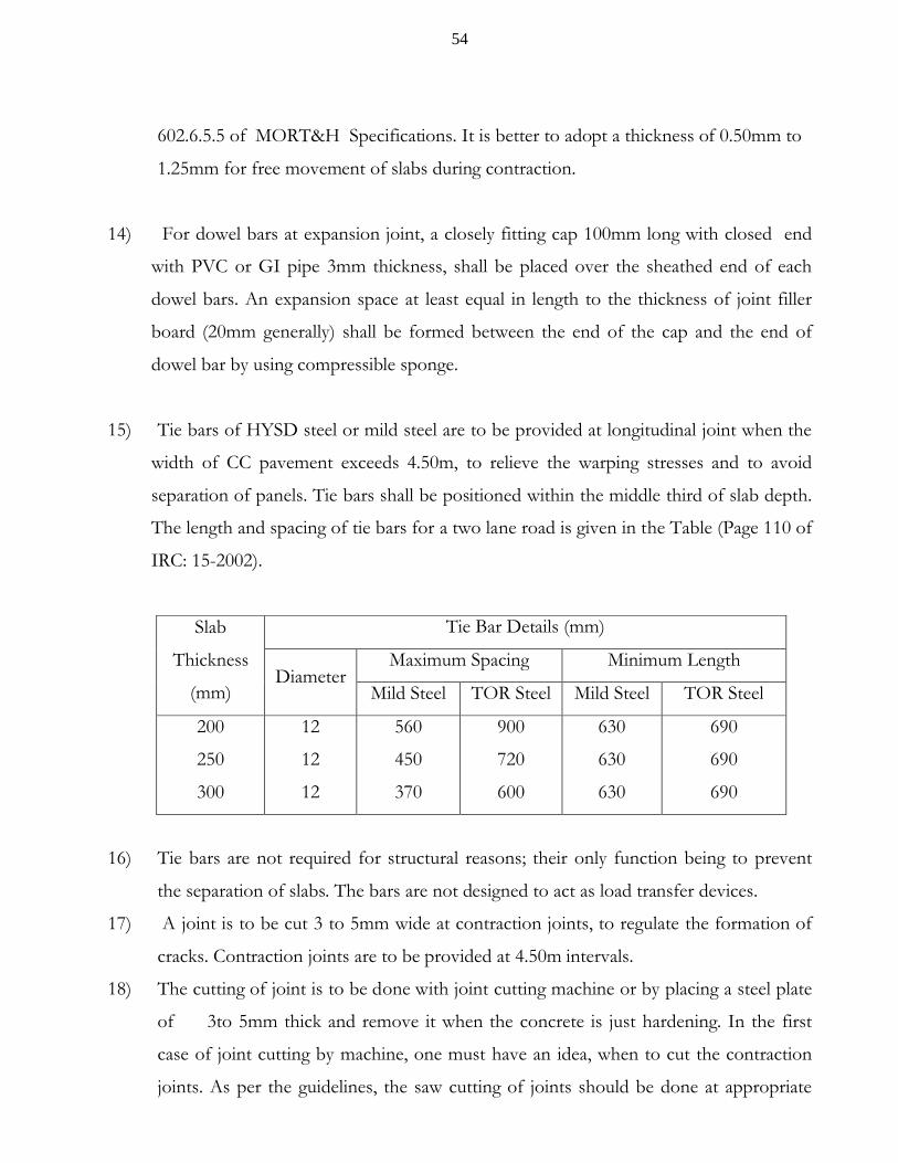
54
602.6.5.5 of MORT&H Specifications. It is better to adopt a thickness of 0.50mm to
1.25mm for free movement of slabs during contraction.
14) For dowel bars at expansion joint, a closely fitting cap 100mm long with closed end
with PVC or GI pipe 3mm thickness, shall be placed over the sheathed end of each
dowel bars. An expansion space at least equal in length to the thickness of joint filler
board (20mm generally) shall be formed between the end of the cap and the end of
dowel bar by using compressible sponge.
15) Tie bars of HYSD steel or mild steel are to be provided at longitudinal joint when the
width of CC pavement exceeds 4.50m, to relieve the warping stresses and to avoid
separation of panels. Tie bars shall be positioned within the middle third of slab depth.
The length and spacing of tie bars for a two lane road is given in the Table (Page 110 of
IRC: 15-2002).
Slab
Thickness
(mm)
Tie Bar Details (mm)
DiameterMaximum Spacing Minimum Length
Mild Steel TOR Steel Mild Steel TOR Steel
200
250
300
12
12
12
560
450
370
900
720
600
630
630
630
690
690
690
16) Tie bars are not required for structural reasons; their only function being to prevent
the separation of slabs. The bars are not designed to act as load transfer devices.
17) A joint is to be cut 3 to 5mm wide at contraction joints, to regulate the formation of
cracks. Contraction joints are to be provided at 4.50m intervals.
18) The cutting of joint is to be done with joint cutting machine or by placing a steel plate
of 3to 5mm thick and remove it when the concrete is just hardening. In the first
case of joint cutting by machine, one must have an idea, when to cut the contraction
joints. As per the guidelines, the saw cutting of joints should be done at appropriate

55
time, when the concrete has attained adequate strength required, so that the concrete is
not disturbed. The saw cutting should be done, when the strength of concrete is
between 3.0MPa to 10.0 MPa (3.0 N/mm2 to 10.0 N/mm2). For M35 grade concrete,
this strength is achieved in 24 hours to 36 hours. As a general guide, the saw cutting
for M35 grade should be done between 24 to 36 hours after laying of concrete. If the
cutting is done before 24 hours, the concrete will be disturbed and the joint will be
shabby. If the cutting is done after 36 hours it is difficult to cut the groove, to the
required depth.
Many field engineers are taking up the cutting of joints after total
completion of curing period which is incorrect and very difficult. The saw cutting may
be taken up as discussed above not later than 36 hours after placing concrete.
19) At expansion joints, we must provide mastic pad to relieve the compressive stresses, at
joint locating due to expansion of C. C. slabs. There are no guidelines regarding the
spacing of expansion joints, except to provide them at culvert and bridge abutments.
The present practice is to omit expansion joints altogether(Clause No. N.2.4 of
IRC: 15-2002). However it is generally adopted at 6 panels to avoid problems at a
later date.
20) No traffic shall be allowed until the curing is totally completed for a period of 28 days.
21) Joints are to be sealed with joint sealing compound after 28 days of curing to avoid
ingress of foreign material into the joints. Any sand, dust entered into the joints during
the process of curing, should be thoroughly cleaned and air blown before laying joint
sealing compound. Joint sealing should be done before opening to traffic.
22) Curing must be started by sprinkling water after final setting time of cement is over
and no impressions can be seen due to sprinkling water. It is always advantageous to
keep the concrete wet from 12 hours. The lapses with us are (i) The curing started late
after 24 hours, (ii) Inadequate curing period i.e., stopping curing at an earlier age of 7 to
10 days, (iii) Keeping the concrete surfaces dry even during this short curing period. All
these omissions land us in troubles.
56
In order to mitigate this problem, the following methods may be adopted.
i) Stop laying of M35 grade concrete by 2:00 PM every day, allow it to dry for 6
to 8 hours. Then construct dykes (small bunds of mortar or earth) on the same
day evening. Start ponding of water in the early hours of next morning.
Meanwhile you can sprinkle water depending on the hardening of concrete
ii) After stopping, the concrete of M35 grade the workers may be asked to lay
bed concrete, so that the bed concrete will be ready for laying C. C. pavement.
iii) The stopping of M35 grade concrete early permits the masons to remove the
excess laitance formed due to vibration, on the top surface of concrete and to
brush the surface for obtaining the texture of required.
iv) When joints are formed manually by placing steel plate the joints can be
made to line and level after removing the steel plate before the sun sets.
v) The side forms can be removed and honey combs finished on the same day,
so that curing need not be stopped for hardening of this finished surfaces.
Because of this many contractors stop curing for the 2nd day completely and start
curing on the forenoon of 3rd day. That means curing will be started after 36
hours of laying of concrete. The strength of concrete at 36 hours if cured
properly will be 31%. For M35 grade it works out to 10.85 N/mm2. If you don’t
provide adequate water during this period, the damage caused cannot be rectified
and we have to face the problems. One must keep this in mind, while executing
concrete items.
Many of us feel that who will follow this, when labour leaves by 6 PM. The Masons
may be paid extra to keep them available up to 9:00 PM to have durable and high strength
concrete. Please remember where there is a will, there is a way and we can do this if we have
the will.

57
INCREASE IN STRENGTH OF CONCRETE WITH AGE
The Concrete mix starts reaction of cement and water immediately they are added. The
initial setting time is generally 30 minutes and final setting time not more than 600 minutes.
Modern days cement has earlier final setting of 6 hours or less. The hardening process of
concrete is assumed to have started after final setting time. In order to have some idea,
regarding the strength of concrete, a ready to use table is available in MORT&H
specifications Book. The same is reproduced here for reference. It is to be noted that the
strength of concrete increases very rapidly in 48 hours up to 40%, 7 days up to 74% and
thereafter, the strength increases slowly. Even after 28 days the concrete has a tendency to
have increase in compressive strength. The increase is more dominant in case of Portland
Pozollona Cement (PPC).
No. of days 1 2 3 4 5 7 10 14 21Strength (%) 20.50 41.00 50.50 60.00 65.50 74.25 81.50 87.50 95.00
No. of days 28 30 45 50 60 75 90Strength (%) 100.00 104.00 108.75 110.5 114.00 117.75 121.00
No. of days 100 115 150 180 200 360Strength (%) 123.50 125.50 130.50 133.50 135.50 146.00
From the above table, one can say that M35 grade concrete laid will have 100% strength
of 35 N/mm2 at 28 days, 39.90 N/mm2 at 60 days, 46.725 N/mm2 at 180 days, 57.10 N/mm2
at 360 days. This is likely to be revised in the next revision, as lots of arguments are going
against this. Until then we have to follow this table.

58
14) MYTHS & FACTS ABOUT CONCRETE
Myth Fact
1 Very hard metal is to be used for concrete
Aggregate of very hard nature is not essential for concrete. Concrete with AIV less than 45 is suitable for all grades of concrete except for wearing surfaces viz. wearing coat of bridges, CC pavements, etc. For wearing surfaces aggregate having AIV less than 30 is to be used. Gradation of aggregate is more important for concrete to have more strength. Hence trap metal or other reasonably hard material satisfying the above requirements can be used for any grade of concrete. For BT/CC roads we must use aggregate having AIV less than 30, which means very hard material is required for roads rather than other structures like bridges.
2 Water used for mixing must be good. Water used for curing need not be that much good used for mixing
Water used for mixing and curing must have the same specification and must satisfy the condition of PH value more than 6.
3 Flaky materials should not be used for concrete
Flaky materials with FIV up to 35 can be used for concrete. IRC: 44 permit aggregates having FIV upto 40 for CC pavements.
4 Use of more water in mixing gives dense concrete and good finishing durable
Use of more water leaves more voids in concrete after completion of hardening process. The presence of voids reduces concrete strength considerably. The presence of 5% voids reduces the concrete strength by 30%.
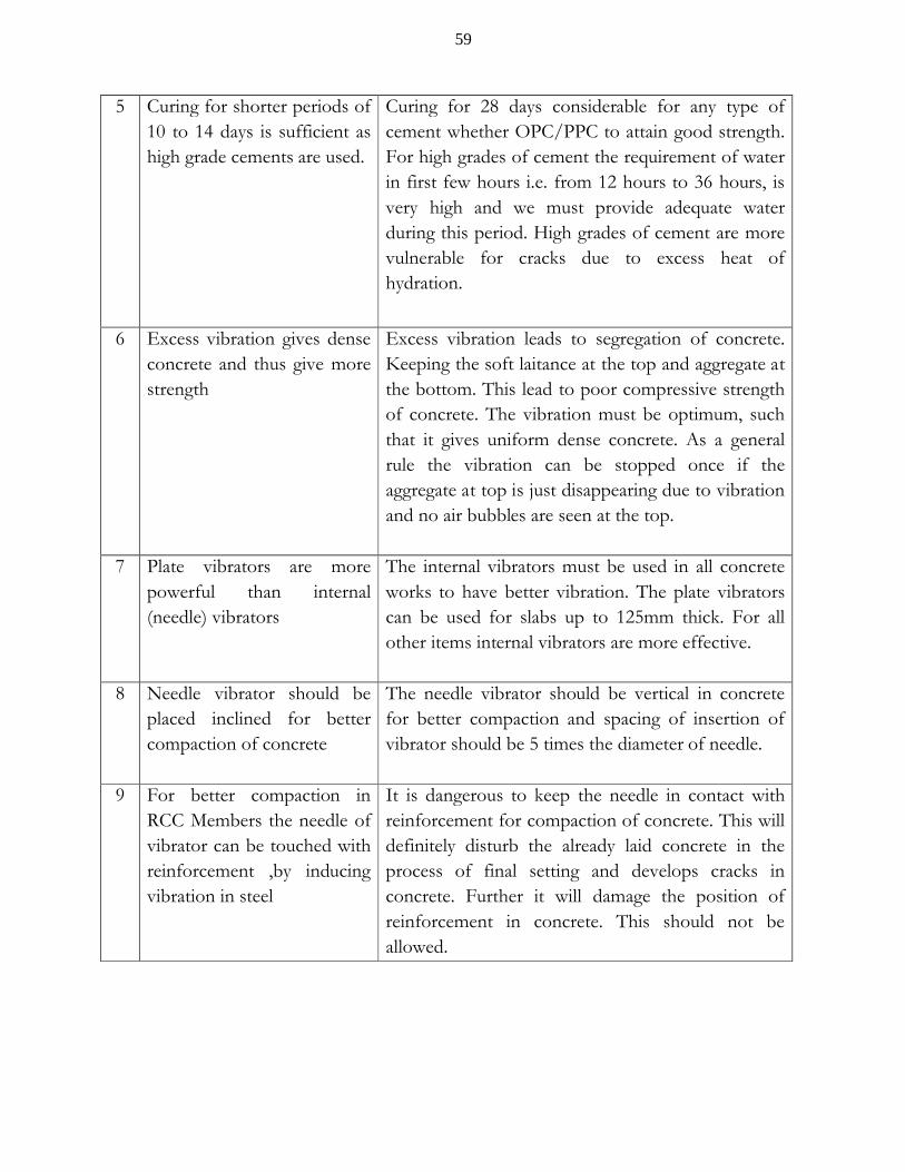
59
5 Curing for shorter periods of 10 to 14 days is sufficient as high grade cements are used.
Curing for 28 days considerable for any type of cement whether OPC/PPC to attain good strength. For high grades of cement the requirement of water in first few hours i.e. from 12 hours to 36 hours, is very high and we must provide adequate water during this period. High grades of cement are more vulnerable for cracks due to excess heat of hydration.
6 Excess vibration gives dense concrete and thus give more strength
Excess vibration leads to segregation of concrete. Keeping the soft laitance at the top and aggregate at the bottom. This lead to poor compressive strength of concrete. The vibration must be optimum, such that it gives uniform dense concrete. As a general rule the vibration can be stopped once if the aggregate at top is just disappearing due to vibration and no air bubbles are seen at the top.
7 Plate vibrators are more powerful than internal (needle) vibrators
The internal vibrators must be used in all concrete works to have better vibration. The plate vibrators can be used for slabs up to 125mm thick. For all other items internal vibrators are more effective.
8 Needle vibrator should be placed inclined for better compaction of concrete
The needle vibrator should be vertical in concrete for better compaction and spacing of insertion of vibrator should be 5 times the diameter of needle.
9 For better compaction in RCC Members the needle of vibrator can be touched with reinforcement ,by inducing vibration in steel
It is dangerous to keep the needle in contact with reinforcement for compaction of concrete. This will definitely disturb the already laid concrete in the process of final setting and develops cracks in concrete. Further it will damage the position of reinforcement in concrete. This should not be allowed.

60
REFERENCE CODES
1) IS 456-2000 :CODE OF PRACTICE FOR PLAIN AND REINFORCED CONCRETE
2)IRC 44-2008 :GUIDELINES FOR CEMENT CONCRETE MIX DESIGNFOR PAVEMENTS (SECOND REVISION)
3)IRC 15-2002 :STANDARD SPECIFICATION AND CODE OF PRACTICE FOR CONSTRUCTION OF CONCRETE ROADS
4) IS 516-1959 :METHODS OF TESTS FOR STRENGTH OF CONCRETE
5)IS 1199-1959 :METHODS OF SAMPLING AND ANALYSIS OF CONCRETE
6) SPECIFICATIONS FOR ROADS AND BRIDGE WORKS MORT&H (FOURTH REVISON)
.