revision 1 to calculation ano-34q-326, 'pressurizer level
TRANSCRIPT
Attachment 7 to
1 CAN041004
Pressurizer Level Sensing/Sampling Nozzle (No Existing Pad)-
Repair Fracture Mechanics Analysis
Non-Proprietary
Structural Integrity CALCULATION File No.: ANO-34Q-326
Associates, Inc. PACKAGE Project No.: ANO-34Q
PROJECT NAME: Pressurizer Small Bore Nozzle Repairs
Contract No.: 32226, Revision 2CLIENT: Welding Services Inc. PLANT: Arkansas Nuclear One, Unit 1
CALCULATION TITLE: Pressurizer Level Sensing/Sampling Nozzle (no existing pad) RepairFracture Mechanics Analysis
Project Mgr. Preparer(s) &Document Affected Approval Checker(s)Revision Pages Revision Description Signature & Signatures &
Date Date
0 1-53 Original IssueA1-A3 G. Mukhim C. Fourcade
Computer GSM 12-20-06 CJF 12-20-06Files
G. MukhimGSM 12-20-06
1 1-53 Editorial change. Revised wording inA 1- A3 Section 6 to state that EPFM will be z A" .
performed GSM CJF-- 7- o17
GSM,0---7_07
Page 1 of 53
SI Form F2001R2a
Table of Contents
1 IN T R O D U C T IO N ................................................................................................................................ 42 M E T H O D O L O G Y ................................................................................................................................ 43 A S SU M PT IO N S ................................................................................................................................... 5'4 A N A L Y S IS ............................................................................................................................................ 5
4.1 Finite E lem ent M odel ................................................... ........................................................ 54.2 B oundary C onditions ........................................................................................................... 64.3 Superposition Technique ............................................. 64 .4 L o ad s .................................................................................. ....................................................... 7
5 RESULTS' OF ANALYSIS ........................................................ 105.1 A llow able Stress Intensity Factors .............. .........................................................
6 CONCLUSIONS ...................................................... 127 REFERENCES ....... .. ............................... ................ I . ........... 53APPENDIX A ANSYS FILENAME LISTING ................................................................................ Al
List of Tables
Table 1: Flaw 1 Stress Intensity Factor Summary .................................................................................. 13
Table 2: Flaw 2 Stress Intensity Factor Summary .......................................................................... 0 14
Table 3: Flaw 3 Stress Intensity Factor Summary ......................................................... 15
Table 4: Flaw 1 Total Stress Intensity Factor Summary ............................... 16
Table 5: Flaw 2 Total Stress Intensity Factor Summary ..................................................................... 17
Table 6: Flaw 3 Total Stress Intensity Factor Summary ......................... ............................................ 18
Table 7: Stress Intensity Factor Summary .......................................................................................... 19
List of Figures
Figure 1: J-groove Crack Dimensions ................................................................................................. 20
Figure 2: Finite E lem ent M odel .............................................................................................................. 21
Figure 3: Boundary Conditions (Flaw 3) ............................................................................................ 22
Figure 4: 1,000 psi Uniform Crack Face Pressure (Flaw 3) .................................. 23
Figure 5: 1,000 psi Internal Pressure Hoop Stress ........................................ 24
Figure 6: Residual Stress at Crack Face (Flaw 3) .............................................................................. 25
Figure 7: Steady-State (650'F) Hoop Stress ....................................... 26
Figure 8: Nodal Locations for Sampling Hoop Stress and Temperature ............................................ 27
Figure 9: Hoop Stress History in J-groove Region for Heatup ................... ...................................... 28
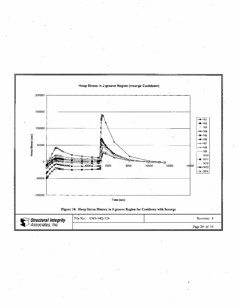
Figure 10: Hoop Stress History in J-groove Region for Cooldown with Insurge ................................ 29
Structural Integrity File No.: ANO-34Q-326 Revision: 1
Associates, Inc. Page 2 of 53
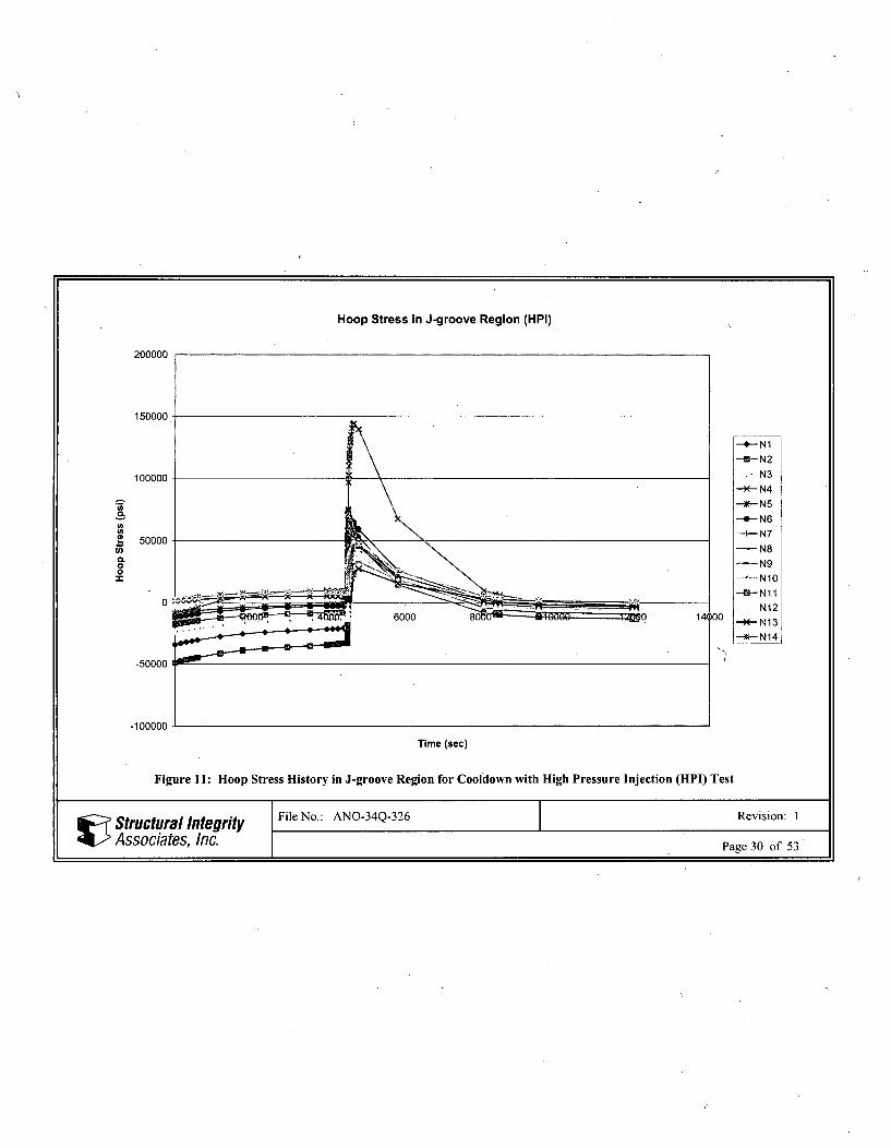
Figure 11: Hoop Stress History in J-groove Region for Cooldown with High PressureInjection (H P I) T est .................................................................................................... I ........... 30
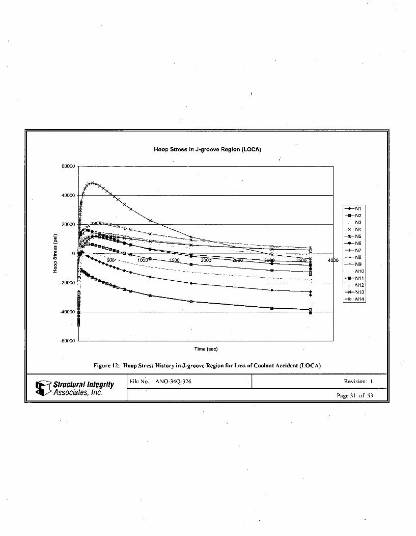
Figure 12: Hoop Stress History in J-groove Region for Loss of Coolant Accident (LOCA) ............. 31Figure 13: Heatup Hoop Stress Field, Time 20,880 sec .................................................................. 32
Figure 14: Cooldown with Insurge Hoop Stress Field, Time = 5,323 sec .......................................... 33
Figure 15: Cooldown with High Pressure Injection Test (HPI) Hoop Stress Field, Time = 4,534 sec ... 34Figure 16: Loss of Coolant Accident (LOCA) Hoop Stress Field, Time = 25 sec .................................. 35
Figure 17: Crack Tip Numbering in ANSYS Analyses ........ ............................................................... 36Figure 18: Crack Face Pressure Stress Intensity Factor ....................................................................... 37Figure 19: Internal Pressure Stress Intensity Factor ........................................................................... 38
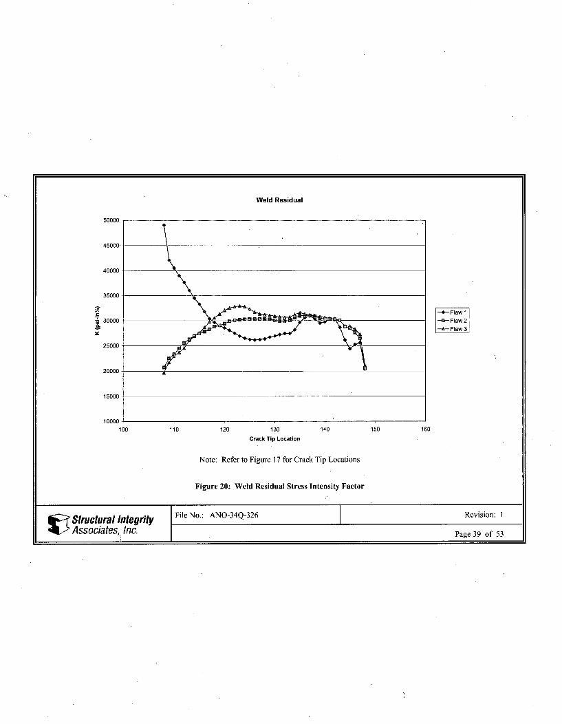
Figure 20: Weld Residual Stress Intensity Factor .............................................................................. 39
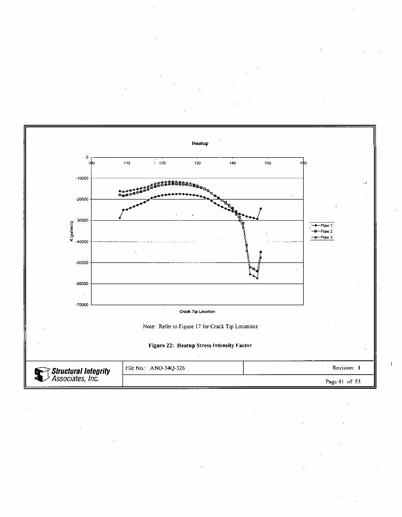
Figure 21: Steady-State (650'F) Stress Intensity Factor ..................................................................... 40Figure 22: H eatup Stress Intensity Factor .......................................................................................... 41
Figure 23: Cooldown with Insurge Stress Intensity Factors at Selected Times .................................. 42Figure 24: Cooldown with High Pressure Injection Test (HPI) Stress Intensity Factors at
S elected T im es ...................................................................................................................... 43Figure 25: Loss of Coolant Accident (LOCA) Stress Intensity Factors at Selected Times ................. 44
Figure 26: Cooldown with Insurge Maximum Thermal Stress Intensity Factor ................................ 45
Figure 27: Cooldown with High Pressure Injection Test (HPI) Maximum Thermal StressIn ten sity F actor ........................................................................................................................ 46
Figure 28: Loss of Coolant Accident (LOCA) Maximum Thermal Stress Intensity Factor ............... 47
Figure 29: Heatup Total Stress Intensity Factor ................................................................................ 48Figure 30: Cooldown with Insurge Total Stress Intensity Factor ..................................................... 49
Figure 31: Cooldown with HPI Total Stress Intensity Factor .............................................................. 50
Figure 32: LOCA Total Stress Intensity Factor ................................................................................... 51
Figure 33: Steady-State (650'F) Total Stress Intensity Factor ........................................................... 52
SStructural Itegrity File No.: ANO-34Q-326 Revision: 1
Associates, Inc. Page 3 of 53
1 INTRODUCTION
The objective of this calculation is to perform fracture mechanics analyses due to thermal transients, weldresidual stress, mechanical loads, and internal pressure on the outside diameter (OD) repairs for thefollowing pressurizer nozzles for the pressurizer at ANO, Unit 1.
* Two upper level sensing nozzles (no existing pad)• Two lower level sensing nozzles* One sampling nozzle* One modified level sensing nozzle with thermowell replacement
Details of the proposed repairs (except the modified level sensing nozzle) have been discussed in aseparate finite element model development calculation [1]. Details of the proposed repairs for themodified level sensing nozzle with thermowell replacement have been described in Reference 12.
This analysis is applicable to the modified level sampling nozzle with thermowell replacement becausethe J-groove region (including the original stub-tube) in the pre-repaired nozzle is similar to the otherlevel sensing nozzles, and is considered unaffected by the OD repair.
Stress intensity factors resulting from internal pressure, thermal transient events, MNSA loads, and weldresidual stress will be determined for the flaw at the interface between the J-groove weld and thepressurizer wall. The flaw is assumed to be oriented in the axial direction of the pressurizer. The flaw isassumed in the axial orientation because the hoop stresses, which act to open the crack, are typicallyhigher than the axial stresses which act along the axial direction of the pressurizer. Three separate flawsare modeled and analyzed, assuming self-similar crack growth.. The stress intensity factor resultsdetermined herein will be used in a future fatigue crack growth evaluation.
2 METHODOLOGYThe fracture mechanics analysis is performed using the following methodology:
" -Modeling of the assumed flaw (crack tip element generation) was performed in the previous modeldevelopment [1]. Only boundary conditions need to be implemented in this analysis to define thecrack front boundary.
* The entire J-groove weld and local cladding is assumed initially flawed, as well as part of the faceof the original nozzle. Three separate cracks are modeled, assuming self-similar crack growth.The flaw configurations are shown in Figure 1.
" Determine the times of maximum hoop stress in the region of the flaw (J-groove region) for eachthermal transient. The thermal analysis databases are resumed at these times from the Reference 2analysis to extract nodal temperature data, the appropriate crack face boundary conditions areapplied, and the solution is obtained.
* The fracture mechanics features of ANSYS [5] are utilized to calculate the stress intensity factorsalong the crack front of each flaw for the selected thermal transient times mentioned above, andcombined with stress intensity factors from the weld residual stress and internal pressure analyses.
Structural In File No.: ANO-34Q-326 Revision: 1
Associates, Inc. Page 4 of 53
3 ASSUMPTIONS
The fracture mechanics evaluation is performedwith the following assumptions:
The portion of the axial flaw in the penetration weld is initially assumed to be at the interfacebetween the J-groove weld and the base material of the pressurizer wall. The nozzle remnant isassumed to be cracked through-wall, with the vertical portion extending up to the height of the J-groove crack. Subsequent flaw configurations incorporate incremental crack growth, assumingself-similar crack growth (a conservative approach). The flaw size and shape of the three flawconfigurations are shown in Figure 1.
* The flaws are assumed to be oriented along the axial direction of the pressurizer, as this is theorientation where the hoop stresses tend to open the crack.
4 ANALYSIS
For the purpose of this fracture mechanics evaluation, the model from Reference 1 is modified asappropriate to determine stress intensity factors due to internal pressure, weld residual stress, MNSAloads, and thermal transients, as described in the following subsections.
4.1 Finite Element Model
The finite element model was developed in a previous calculation package [1] using the ANSYS finiteelement software package [5]. The model includes a portion of the cylindrical pressurizer shell, vessel IDcladding, existing J-groove weld, existing nozzle, repair nozzle, OD repair pad, and repair attachmentweld. The finite element model covers a quarter of the repair assembly, as shown in Figure 2.
The postulated crack is oriented along the axial direction of the pressurizer. The entire J-groove weld andcladding is assumed initially cracked, extending to the J-groove/pressurizer interface, and through-wall inthe nozzle body. Three separate cracks are modeled, assuming self-similar crack growth. The as-modeledflaws are shown in Figure 1 for the Flaw 1 (initial flaw), Flaw 2 (extended flaw), and Flaw 3 (final flaw)configurations.
The finite element model was constructed such that the crack tip region is sufficiently detailed for thestress intensity factor calculation. Eight-node structural solid brick finite elements (SOLID45) from theANSYS element library were used for the model except for the crack fronts, which were built withquadratic 20-node elements'(SOLID95). In order to model the singularity at the crack tip, the mid-sidenodes of the crack front elements were moved to the quarter point locations.
The material properties used in this analysis for stress intensity factor calculations are the modulus ofelasticity and Poisson's ratio. The modulus of elasticity is taken at 70'F for the stress intensity factorcalculation for the residual stress analysis and for the internal pressure case. For the thermal transients, themodulus of elasticity (used for the K calculation) is calculated internally by ANSYS, based on the nodaltemperature at each crack tip location. A constant Poisson's ratio of 0.3 is used for all the materials. Thestress-free reference temperature was taken as 70'F for all analyses.
Structural integrity File No.: ANO-34Q-326 Revision: 1L Associates, Inc. Page 5 of 53
4.2 Boundary Conditions
The edges of the pressurizer finite element model are set far from the nozzle penetration in order toeliminate any end effects in the region of interest. Symmetric boundary conditions are applied at thesymmetry planes, except on the crack face, as shown in Figure 3, for the Flaw 3 configuration, forexample. The crack face is free to displace. These boundary conditions are applicable to all three crackconfigurations for all loading conditions.
4.3 Superposition Technique
The same finite element model is used to generate stresses from basic loads for all cases except theresidual stress analysis. For the residual stress case, stresses obtained from another nearly identicalgeometric finite element model of the nozzle [4], which does not contain the crack (or the repair), are inputas pressures on the crack face, using a standard fracture mechanics superposition technique.
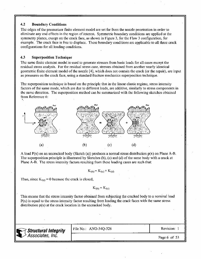
The superposition technique is based on the principle that in the linear elastic regime, stress intensityfactors of the same mode, which are due to different loads, are additive, similarly to stress components inthe same direction. The superposition method can be summarized with the following sketches obtainedfrom Reference 6:
PP() PW )
(a) (b) (c) (d)
A load P(x) on an uncracked body (Sketch (a)) produces a normal stress distribution p(x) on Plane A-B.The superposition principle is illustrated by Sketches (b), (c) and (d) of the same body with a crack atPlane A-B. The stress intensity factors resulting from these loading cases are such that:
KI(b) = KI(C) + KI(d)
Thus, since KI(d) = 0 because the crack is closed,
KI(b) = KI(c)
This means that the stress intensity factor obtained from subjecting the cracked body to a nominal loadP(x) is equal to the stress intensity factor resulting from loading the crack faces with the same stressdistribution p(x) at the crack location in the uncracked body.
Structural Integrity File No.: ANO-34Q-326 Revision: 1
, Associa~tes, Inc. Page 6 of 53
4.4 Loads
The following loads are considered:
Crack Face Pressure Stress
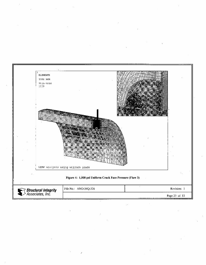
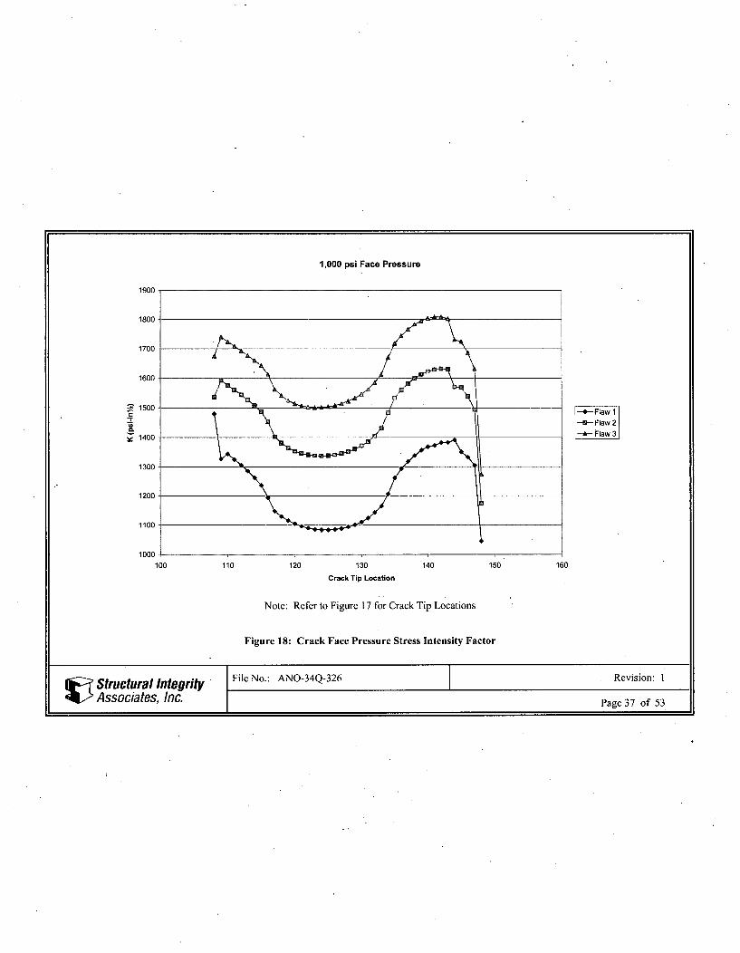
An evenly distributed uniform crack face pressure of 1,000 psi is dpplied on the crack face of the model inorder to account for the internal pressure that acts on the face of the crack. The applied pressure is shownin Figure 4 for the Flaw 3 configuration, for example. Results from the 1,000 psi pressure case can bescaled to the appropriate pressure value, consistent with the loading conditions being considered. TheANSYS input file names are ANOLVL_3D_GEOM2_UNIF 1.INP,ANOLVL_3DGEOM2_UNIF2.INP, and ANO_LVL_3DGEOM2_UNIF3.INP, for the Flaw 1, Flaw 2,and Flaw 3 configurations, respectively.
Internal Pressure Stress
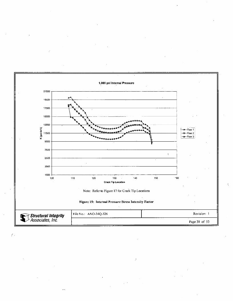
A unit pressure load of 1,000 psi is applied to all internal surfaces ofthe model, and an end-cap pressure isapplied to the end of the pressurizer and nozzle, as in Reference 1. The hoop stress field is shown inFigure 5. Results from the 1,000 psi pressure case can be scaled to the appropriate pressure value,consistent with the loading conditions being considered. The ANSYS input file names arePINTLVLFRACTUREI.INP, PINTLVLFRACTURE2.INP, and PINTLVLFRACTURE3.INP, forthe Flaw 1, Flaw 2, and Flaw 3 configurations, respectively.
Post-Weld Heat Treatment Residual Stress
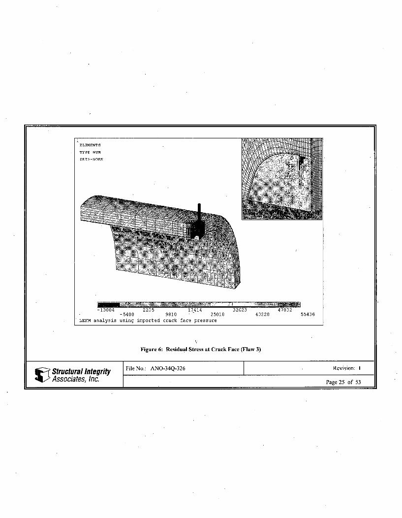
The hoop stresses (global x-direction) on the elements representing the crack face are extracted from theReference 4 analysis at the last load step (at 70'F), and then transferred to the crack face of the fracturemechanics model, using the method described in Section 4.3. The transferred stresses are shown in Figure6 for the Flaw 3 configuration, for example. The ANSYS input file names areANOLVL 3D GEOM2_RESID1.INP, ANO_LVL_3DGEOM2_RESID2.INP, andANO_LVL_3DGEOM2_RESID3.INP, for the Flaw 1, Flaw 2, and Flaw 3 configurations, respectively.
Steady State/Thermal Stress'
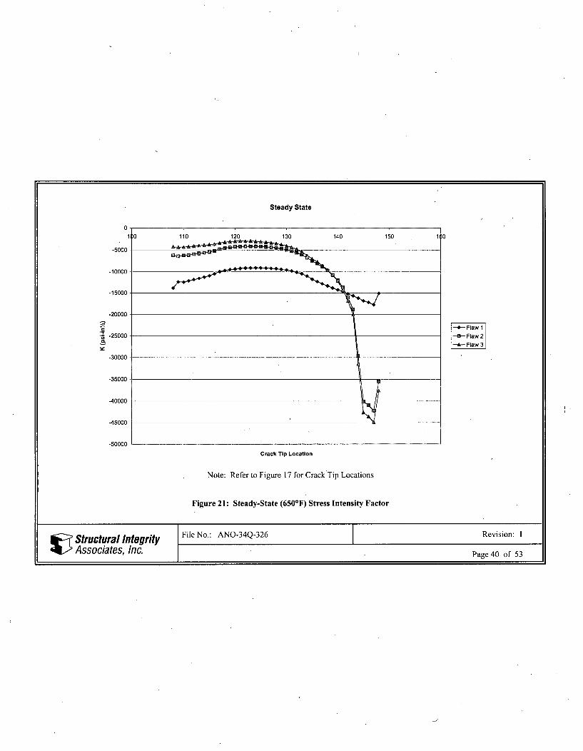
A steady state analysis at 6507F at the first load step (at time 0 seconds) of the cooldown with insurgetransient analysis is performed in Reference 2. To calculate stress intensity factors at the time ofmaximum pressure, nodal temperatures during this time step are read from the thermal analysis database[2] into the stress pass using the ANSYS LDREAD command [5] and applied to the model, and thensolved for stresses. The hoop stress field is shown in Figure 7. The ANSYS input file names areSTEADYLVLFRACTURE1.INP, STEADYLVLFRACTURE2.INP, andSTEADYLVLFRACTURE3.INP for the Flaw 1, Flaw 2, and Flaw 3 configurations, respectively.
Structural Integrity File No.: ANO-34Q-326 Revision: 1
L Associates, Inc. Page 7 of 53
Heatup Thermal Transient
A fracture mechanics analysis is performed at one time point during the heatup transient:
Maximum Compressive Stress
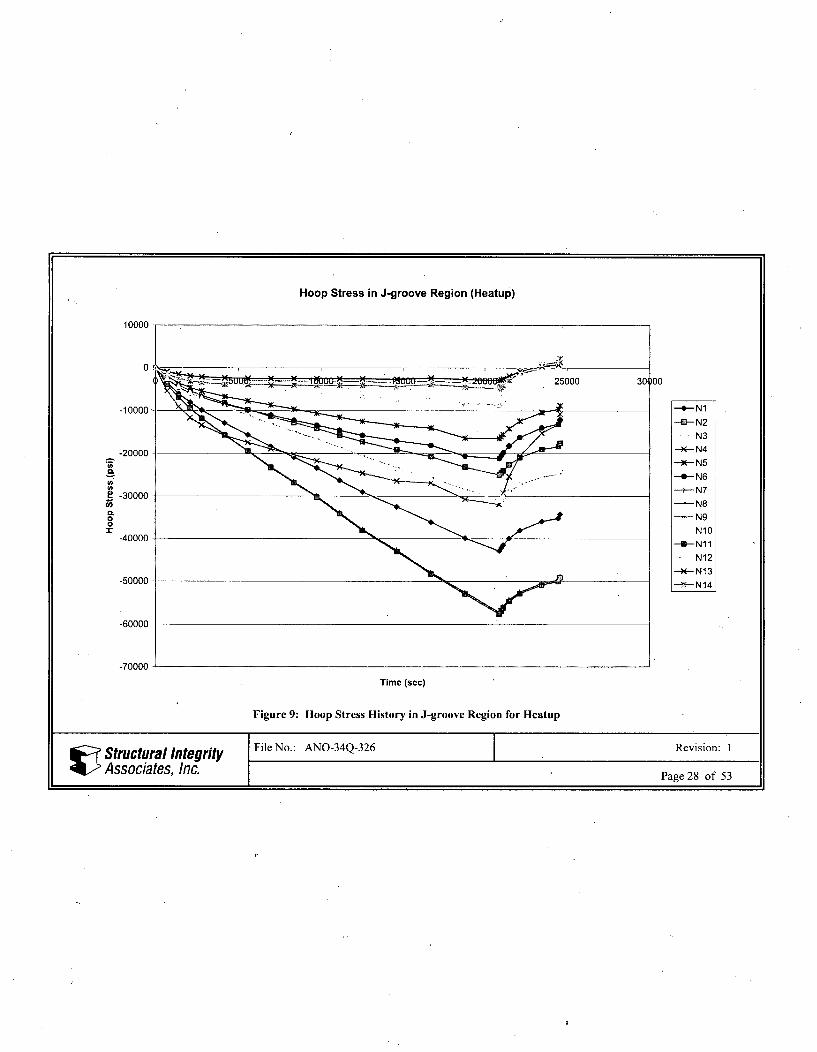
The heatup thermal transient nodal temperature results are extracted from the Reference 2 analysis at thetime of maximum negative (compressive) stresses in the J-groove weld region during the entire transient.In order to determine the time at which to extract the nodal temperature data, fourteen nodes are selectedin the J-groove weld region at various locations around the three crack fronts, as shown in Figure 8. Asseen in Figure 9, the maximum compressive stresses occur at time 20,880 seconds. Therefore, nodaltemperatures during this time step are read from the thermal analysis database [2] into the stress pass usingthe ANSYS LDREAD command [5] and applied to the model, and then solved for stresses. The hoopstress field is shown in Figure 13. The ANSYS input file names are HULVLFRACTURE 1.INP,HULVLFRACTURE2.INP, and HULVLFRACTURE3.INP for the Flaw 1, Flaw 2, and Flaw 3configurations, respectively.
Cooldown with Insurge Thermal Transient
A fracture mechanics analysis is performed at six separate time points during the transient:
Maximum Tensile Stress
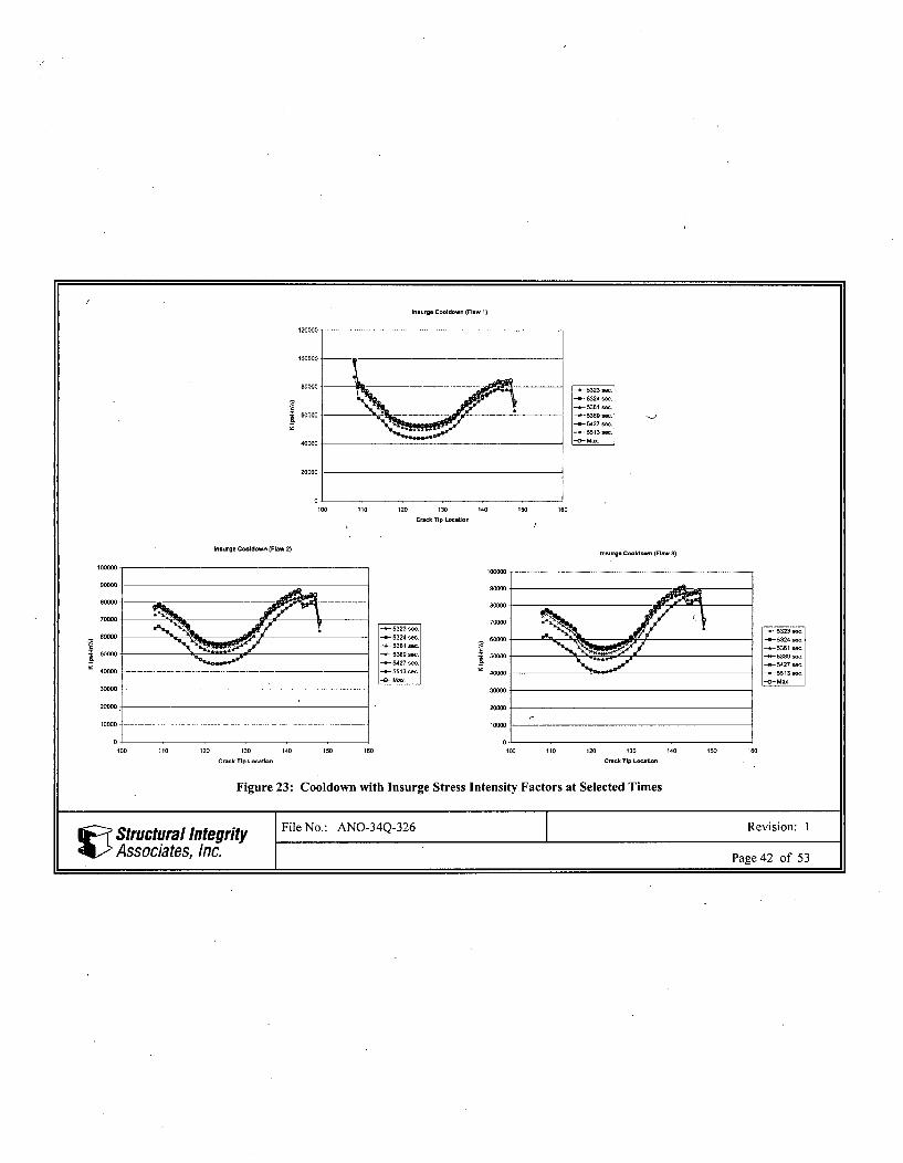
The cooldown with insurge thermal transient nodal temperature results are extracted from the Reference 2analysis at the time of maximum positive (tensile) stresses in the J-groove weld region during the entiretransient. In order to determine the times at which to extract the nodal temperature data, fourteen nodesare selected in the J-groove weld region at various locations around the three crack fronts, as shown inFigure 8. As seen in Figure 10, the maximum tensile stresses occur at six different times: 5,322.7seconds, 5,323.3 seconds, 5,360.7 seconds, 5,388.7 seconds, 5,427.3 seconds, and 5,512.7 seconds.Therefore, nodal temperatures during each of these time steps are read from the thermal analysis database[2] into the stress pass using the ANSYS LDREAD command [5] and applied to the model, and thensolved for stresses. The hoop stress field is shown in Figure 14. The ANSYS input file names areINSURGE LVL FRACTURE1.INP, INSURGE LVL FRACTURE2.INP, andINSURGELVLFRACTURE3.INP for the Flaw 1, Flaw 2, and Flaw 3 configurations, respectively.
Cooldown with High Pressure Injection (HPI) Thermal Transient
A fracture mechanics analysis is performed at six separate time points during the transient:
Maximum Tensile Stress
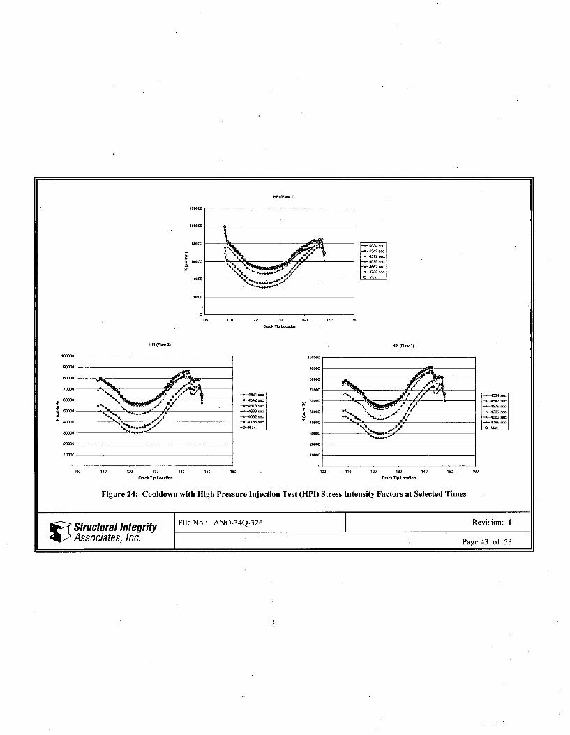
The cooldown with high pressure injection test (HPI) thermal transient nodal temperature results areextracted from the Reference 2 analysis at the time of maximum positive (tensile) stresses in the J-grooveweld region during the entire transient. In order to determine the time at which to extract the nodaltemperature data, fourteen nodes are selected in the J-groove weld region at various locations around thethree crack fronts, as shown in Figure 8. As seen in Figure 11, the maximum tensile stresses occur at sixdifferent times: 4,534 seconds, 4,542 seconds, 4,578.7 seconds, 4638.7 seconds, 4,662 seconds, and
• Structural Integrity File No.: ANO-34Q-326 Revision: I
Associates, Inc. Page 8 of 53
4,786.3 seconds. Therefore, nodal temperatures during each of these time steps are read from the thermalanalysis database [2] into the stress pass using the ANSYS LDREAD command [5] and applied to themodel, and then solved for stresses. The hoop stress field is shown in Figure 15. The ANSYS input filenames are HPILVLFRACTURE1.INP, HPI LVLFRACTURE2.INP, andHPILVLFRACTURE3.INP for the Flaw 1, Flaw 2, and Flaw 3 configurations, respectively.
Loss of Coolant-Accident (LOCA) Thermal Transient
A fracture mechanics analysis is performed at eight separate time points during the transient:F.'
Maximum Tensile Stress
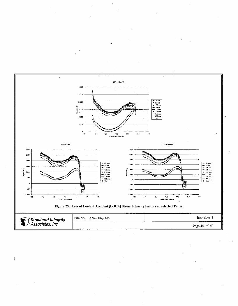
The loss of coolant accident (LOCA) thermal transient nodal temperature results are extracted from theReference 2 analysis at the time of maximum positive (tensile) stresses in the J-groove weld region duringthe entire transient. In order to determine the time at which to extract the nodal temperature data, fourteennodes are selected in the J-groove weld region at various locations around the three crack fronts, as shownin Figure 8. As seen in Figure 12, the maximum tensile stresses occur at eight different times: 25 seconds,29 seconds, 100 seconds, 128.5 seconds, 214 seconds, 271 seconds, 328 seconds, and.385 seconds.Therefore, nodal temperatures during each of these time steps are read from the thermal analysis database[2] into the stress pass using the ANSYS LDREAD command [5] and applied to the model, and thensolved for stresses. The hoop stress field is shown in Figure 16. The ANSYS input file names areLOCALVLFRACTURE1.INP, LOCALVLFRACTURE2.INP, and LOCALVLFRACTURE3.INPfor the Flaw 1, Flaw 2, and Flaw 3 configurations, respectively.
MNSA Analysis
A stress analysis was performed in Reference 11 for the mechanical nozzle seal assembly (MNSA) loads.The hoop stresses (global x-direction) on the elements representing the crack face are extracted from theReference 11 analysis, and then transferred to the crack face of the fracture mechanics model, using themethod described in Section 4.3. The ANSYS input file names are MNSALVLFRACTURE1 .INP,MNSALVLFRACTURE2.INP, and MNSALVLFRACTURE3.INP, for the Flaw 1, Flaw 2, and Flaw3 configurations, respectively. The stress intensity factors for the three flaw configurations are all less
1/2than 100 psi-in' , and are therefore considered negligible.
Mechanical Loads
Based on a review of results in Reference 11, stresses at the crack region due to mechanical loads (otherthan MNSA) are negligible; therefore, stress intensity factors are not computed.
All files are listed in Appendix A, and are included with the project computer files.
Structural Integrity File No.: ANO-34Q-326 Revision: 1
Associates, Inc. Page 9 of 53
5 RESULTS OF ANALYSISStress intensity factors (K) are determined for each of the load cases described in Section 4.4. UsingKCALC, the built-in feature of ANSYS [5] for stress intensity factor calculations, the results of thefracture mechanics analyses are post-processed and the stress intensity factors are determined at multiplelocations along the crack fronts. The crack tip locations as analyzed in ANSYS ("Analysis Crack Tip No."in Tables 1-6) are shown in Figure 17. For presentation purposes, the crack tips for the Flaw 2 and Flaw 3configurations are renumbered to match those of the Flaw 1 configuration ("Adjusted Crack Tip No." inTables 1-6). The stress intensity factor results for pressure (crack face, and internal pressure), residualstress, steady-state thermal conditions, heatup, cooldown with insurge, cooldown with high pressureinjection test (HPI), and loss of coolant accident (LOCA) transient conditions are tabulated in Tables 1through 3. Tables 4 through 6 provide a summary of total stress intensity factors that result from addingthe thermal K values to the appropriately factored pressure and residual stress K values. In addition, stressintensity factors for the highest pressurizer pressure occurring during transient 11 (rod withdrawalaccident) are also evaluated in Tables 4 through 6.
The highest pressurizer pressure from all applicable transients is 2,750 psi based on transient 11 (rodwithdrawal accident). This transient has been re-classified as an emergency condition transient, based onReference 3. This case is combined with steady-state thermal conditions, as shown in Tables 4 through 6,using appropriate allowable K values for emergency/faulted conditions.
Structural Integrity File No.: ANO-34Q-326 Revision: 1
Associates, Inc. Page 10 of 53
The stress intensity factors (K) for the 1,000 psi face pressure, 1,000 psi internal pressure, weld residualstress, steady state conditions, and heatup cases are plotted for the three flaw configurations in Figures 18through 22. Figure 23 contains the K values for the cooldown with insurge transient for all six time. stepsanalyzed, for each flaw configuration. Likewise, Figures 24 and 25 contain the time step K values for thecooldown with HPI. and LOCA transients. Included in Figures 23 through 25 are the maximum boundingthermal K values at each crack tip location, which are presented in Tables 1 through 3, and are used toobtain the total K (thermal+pressure+residual) in Tables 4 through 6.
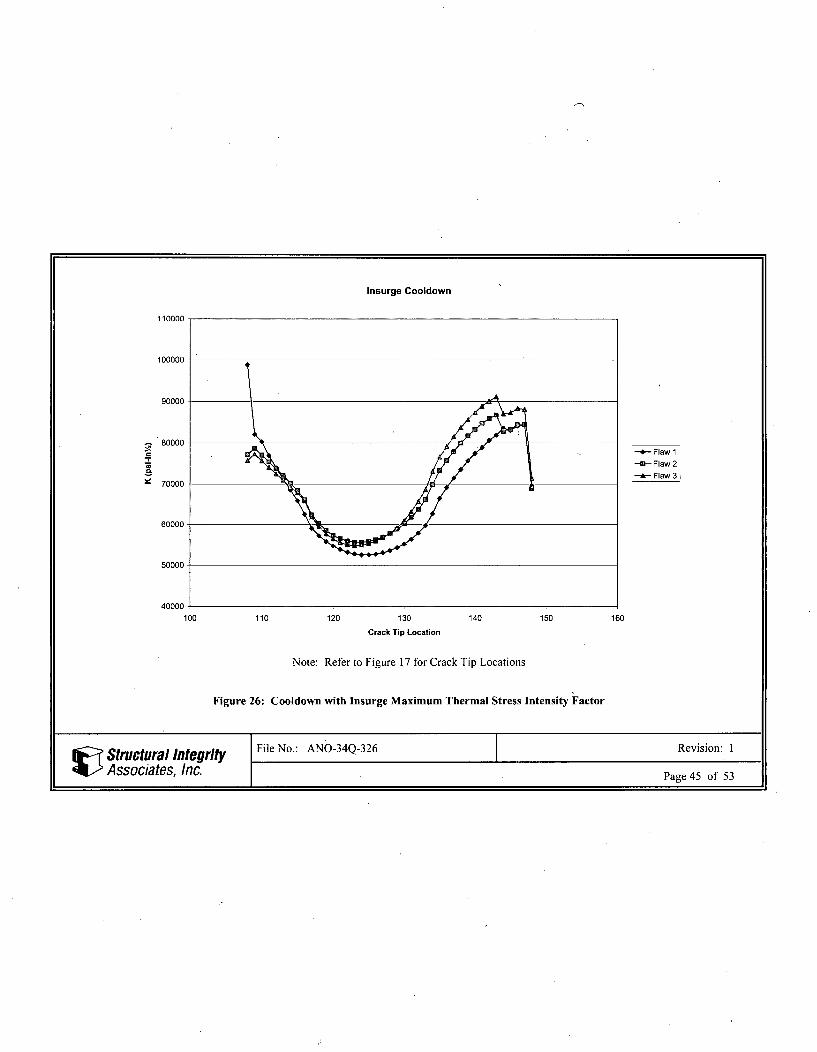
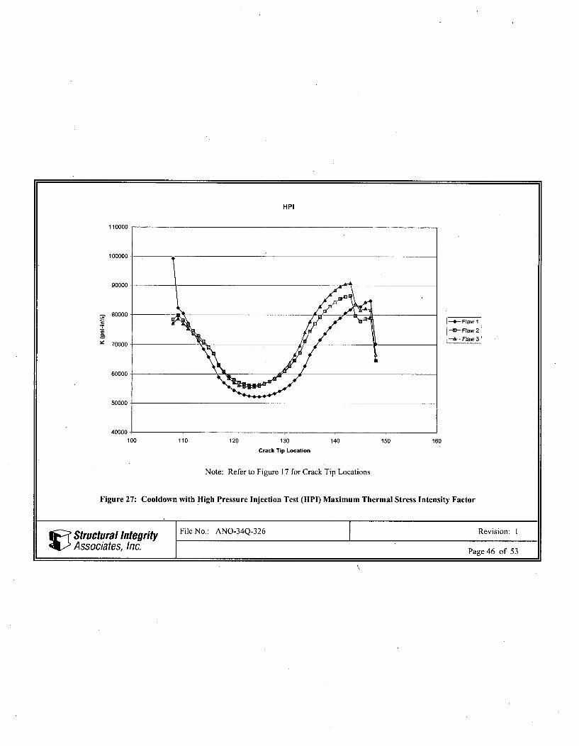
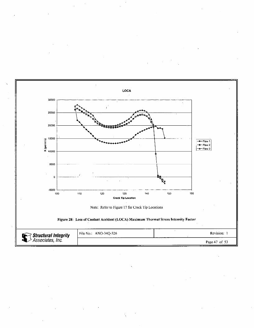
The maximum thermal K values for each crack tip location are plotted in Figures 26 through 28 for thecooldown with insurge, cooldown with HPI, and LOCA analyses, for the three flaw configurations.
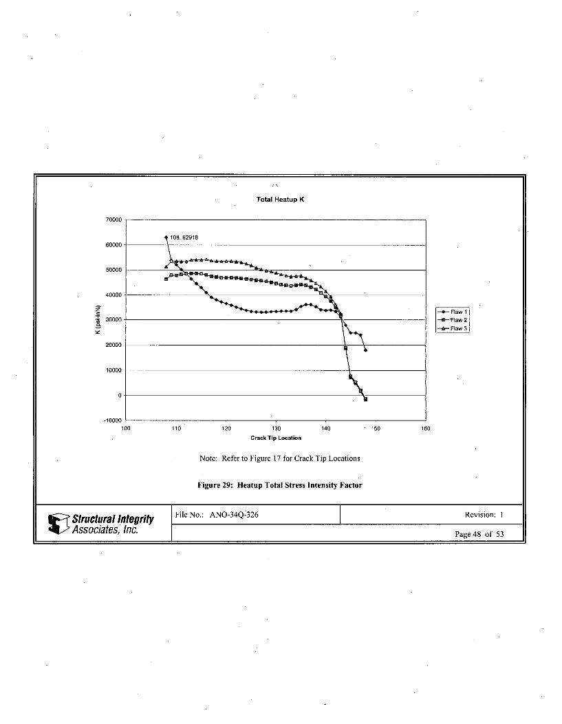
Figures 29 through 33 show plots of the total (thermal+pressure+residual) stress intensity factor values foreach of the thermal transients (heatup, cooldown with insurge, cooldown with HPI, LOCA, and steady-state conditions).
The stress intensity factors are tabulated in Excel spreadsheet LVLFLAW 1-3_K.xls for all transientcases.
All files are listed in Appendix A, and are included with the project computer files.
5.1 Allowable Stress Intensity Factors
For the heatup transient, at temperatures below 11 5°F, a review of the applicable transient curves showsthat pressures are negligible and, therefore, a higher allowable limit of K1c/ N2 can be used fornormal/upset conditions. Thus, stress intensity factors at low temperatures during the heatup transient donot govern.
To calculate the allowable K value, temperatures are obtained at the time of maximum thermal stressintensity factor (for each transient analysis) for the nodal locations that lie on the crack fronts shown inFigure 8. The lowest temperature of all selected locations is then used to calculate a conservativeallowable K value. The calculated allowable values are shown in Tables 4 through 6. Comparisons ofcalculated versus allowable K values are shown in Table 7.
. Structural Integrity File No.: ANO-34Q-326 Revision: 1
Associa .tes, Inc.. Page 11 of 53
As seen in Table 7, the total stress intensity factor (thermal+pressure+residual) for the K due to maximumthermal stress, for the Flaw 1 configuration for cooldown with insurge and cooldown with HPI, are 147.95ksi and 150.27 ksi, respectively, which exceed the ASME Code allowable values of 138.51 ksi and 141.42ksi, respectively. The K values at times of maximum pressure (steady-state) exceed the ASME Codeallowable values for the Flaw 1 and Flaw 3 configurations.
6 CONCLUSIONS
Stress intensity factors are within ASME Code allowable limits for the heatup and LOCA transients, butexceed allowable limits for the steady state conditions with maximum pressure, cooldown with insurge,and cooldown with HPI transients, using linear-elastic fracture mechanics., Therefore, an elastic-plasticfracture mechanics (EPFM) analysis will be performed separately to take advantage of the ductility of thepressurizer material in the upper shelf temperature region.
Structural Integrity File No.: ANO-34Q-326 Revision: 1
Associates, Inc. Page 12 of 53
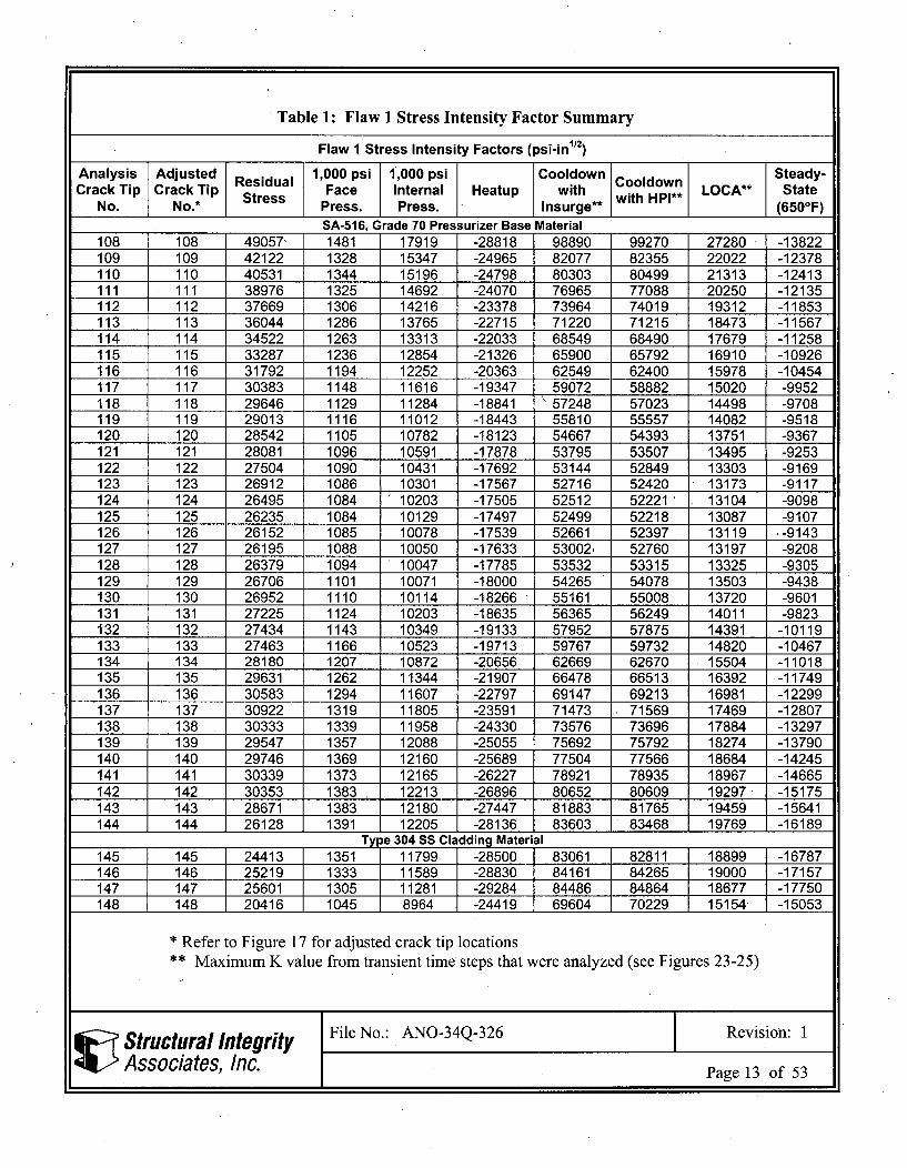
Table 1: Flaw 1 Stress Intensity Factor Summary
Flaw 1 Stress Intensity Factors (psi-in 12)
Analysis Adjusted Residual 1,000 psi 1,000 psi Cooldown Cooldown Steady-Crack Tip Crack Tip Stress Face Internal Heatup with with HPI** LOCA** State
No. No.* Press. Press. lnsurge** (650°F)SA-516. Grade 70 Pressurizer Base Material
108 108 49057- 1481 17919 -28818 98890 99270 27280 -13822109 109 42122 1328 15347 -24965 82077 82355 22022 -12378110 110 40531 1344 15196 -24798 80303 80499 21313 -12413111 111 38976 1325 14692 -24070 76965 77088 20250 -12135112 112 37669 1306 14216 -23378 73964 74019 19312 -11853113 113 36044 1286 13765 -22715 71220 71215 18473 -11567114 114 34522 1263 13313 -22033 68549 68490 17679 -11258115 115 33287 1236 12854 -21326 65900 65792 16910 -10926116 116 31792 1194 12252 -20363 62549 62400 15978 -10454117 117 30383 1148 11616 -19347 59072 58882 15020 -9952118 118 29646 1129 11284 -18841 ' 57248 57023 14498 -9708119 119 29013 1116 11012 -18443 55810 55557 14082 -9518120 120 28542 1105 10782 -18123 54667 54393 13751 -9367121 121 28081 1096 10591 -17878 53795 53507 13495 -9253122 122 27504 1090 10431 -17692 53144 52849 13303 -9169123 123 26912 1086 10301 -17567 52716 52420 13173 -9117124 124 26495 1084 10203 -17505 52512 52221 13104 -9098125 125 26235 1084 10129 -17497 52499 52218 13087 -9107126 126 26152 1085 10078 -17539 52661 52397 13119 -9143127 127 26195 1088 10050 -17633 53002, 52760 13197 -9208128 128 26379 1094 10047 -17785 53532 53315 13325 -9305129 129 26706 1101 10071 -18000 54265 54078 13503 -9438130 130 26952 1110 10114 -18266 55161 55008 13720 -9601131 131 27225 1124 10203 -18635 56365 56249 14011 -9823132 132 27434 1143 10349 -19133 57952 57875 14391 -10119133 133 27463 1166 10523 -19713 59767 59732 14820 -10467134 134 28180 1207 10872 -20656 62669 62670 15504 -11018135 135 29631 1262 11344 -21907 66478 66513 16392 -11749136 136 30583 1294 11607 -22797 69147 69213 16981 -12299137 137 30922 1319 11805 -23591 71473 71569 17469 -12807138 138 30333 1339 11958 -24330 73576 73696 17884 -13297139 139 29547 1357 12088 -25055 75692 75792 18274 -13790140 140 29746 1369 12160 -25689 77504 77566 18684 -14245141 141 30339 1373 12165 -26227 78921 78935 18967 -14665142 142 30353 1383 12213 -26896 80652 80609 19297 -15175143 143 28671 1383 12180 -27447 81883 81765 19459 -15641144 144 26128 1391 12205 -28136 83603 83468 19769 -16189
Type 304 SS Cladding Material145 145 24413 1351 11799 -28500 83061 82811 18899 -16787146 146 25219 1333 11589 -28830 84161 84265 19000 -17157147 147 25601 1305 11281 -29284 84486 84864 18677 -17750148 148 20416 1045 8964 -24419 69604 70229 15154 -15053
* Refer to Figure 17 for adjusted crack tip locations
** Maximum K value from transient time steps that were analyzed (see Figures 23-25)
Structural Integrity File No.: ANO-34Q-326 Revision: 1
Associates, Inc. Page 13 of 53
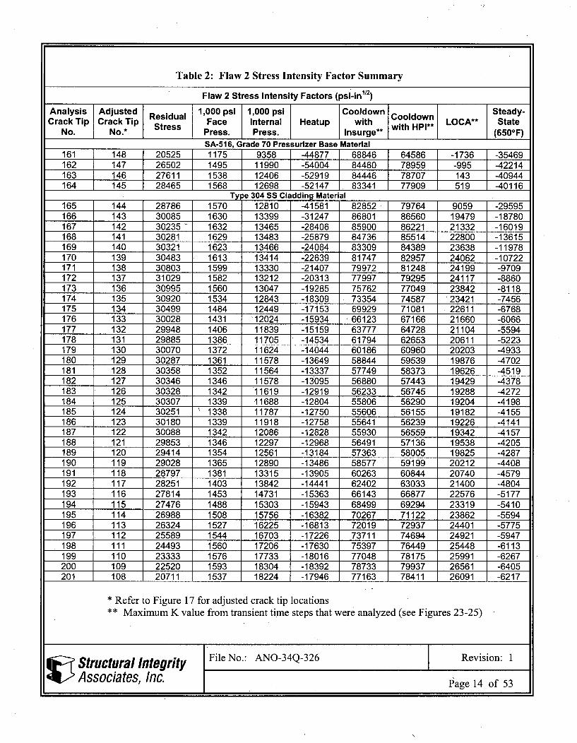
Table 2: Flaw 2 Stress Intensity Factor Summary
Flaw 2 Stress Intensity Factors (psi-inl/2Analysis Adjusted Residual 1,000 psi 1,000 psi Cooldown Cooldown Steady-
Crack Tip Crack Tip Stress Face Internal Heatup with with HPI** LOCA** StateNo. No.* Press. Press. lnsurge* (650OF)
SA-516, Grade 70 Pressurizer Base Material
161 148 20525 1175 9358 -44877 68846 64586 -1736 -35469162 147 26502 1495 11990 -54004 84460 78959 -995 -42214163 146 27611 1538 12406 -52919 84446 78707 143 -40944164 145 28465 1568 12698 -52147 83341 77909 519 -40116
Type 304 SS Cladding Material
165 144 28786 1570 12810 -41581 82852 79764 9059 -29595166 143 30085 1630 13399 -31247 86801 86560 19479 -18780167 142 30235 1632 13465 -28406 85900 86221 21332 -16019168 141 30281 1629 13483 -25879 84736 85514 22800 -13615169 140 30321 1623 13466 -24084 83309 84389 23638 -11978170 139 30483 1613 13414 -22639 81747 82957 24062 -10722171 138 30803 1599 13330 -21407 79972 81248 24199 -9709172 137 31029 1582 13212 -20313 77997 79295 24117 -8860173 136 30995 1560 13047 -19285 75762 77049 23842 -8118174 135 30920 1534 12843 -18309 73354 74587 23421 -7456175 134 30499 1484 12449 -17153 69929 71081 22611 -6768176 133 30028 1431 12024 -15934 66123 67166 21660 -6066177 132 29948 1406 11839 -15159 63777 64728 21104 -5594178 131 29885 1386 11705 -14534 61794 62653 20611 -5223179 130 30070 1372 11624 -14044 60186 60960 20203 -4933180 129 30287 1361 11578 -13649 58844 59539 19876 -4702181 128 30358 1352 11564 -13337 57749 58373 19626 -4519182 127 30346 1346 11578 -13095 56880 57443 19429 -4378183 126 30328 1342 11619 -12919 56233 56745 19288 -4272184 125 30307 1339 11688 -12804 55806 56290 19204 -4198185 124 30251 1338 11787 -12750 55606 56155 19182 -4155186 123 30180 1339 11918 -12758 55641 56239 19226 -4141187 122 30088 1342 12086 -12828 55930 56559 19342 -4157188 121 29853 1346 12297 -12968 56491 57136 19538 -4205189 120 29414 1354 12561 -13184 57363 58005 19825 -4287190 119 29028 1365 12890 -13486 58577 59199 20212 -4408191 118 28797 1381 13315 -13905 60263 60844 20740 -4579192 117 28251 1403 13842 -14441 62402 63033 21400 -4804193 116 27814 1453 14731 -15363 66143 66877 22576 -5177194 115 27476 1488 15303 -15943 68499 69294 23319 -5410195 114 26988 1508 15756 -16382 70267 71122 23862 -5594196 113 26324 1527 16225 -16813 72019 72937 24401 -5775197 112 25589 1544 16703 -17226 73711 74694 24921 -5947198 111 24493 1560 17206 -17630 75397 76449 25448 -6113199 110 23333 1576 17733 -18016 77048 78175 25991 -6267200 109 22520 1593 18304 -18392 78733 79937 26561 -6405201 108 20711 1537 18224 -17946 77163 78411 26091 -6217
• Refer to Figure 17 for adjusted crack tip locations
•* Maximum K value from transient time steps that were analyzed (see Figures 23-25)
Structural Integrity File No.: ANO-34Q-326 Revision: 1
Associates, Inc. Page 14 of 53
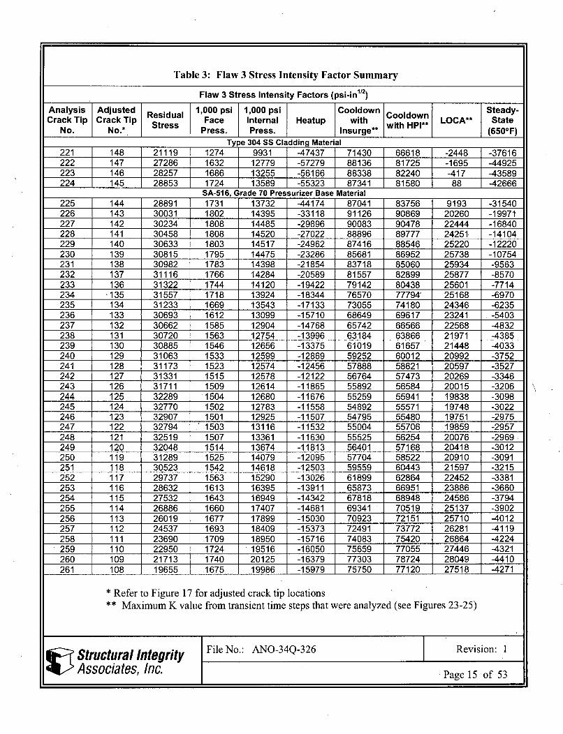
Table 3: Flaw 3 Stress Intensity Factor Summary
Flaw 3 Stress Intensity Factors (psi-in112)
Analysis Adjusted Residual 1,000 psi 1,000 psi Cooldown Cooldown Steady-Crack Tip Crack Tip Stress Face Internal Heatup with LOCA* State
No. No.* Press. Press. Insurge** with HPI** (650°F)Type 304 SS Cladding Material
221 148 21119 1274 9931 -47437 71430 66618 -2448 -37616222 147 27286 1632 12779 -57279 88136 81725 -1695 -44925223 146 28257 1686 13255 -56166 88338 82240 -417 -43589224 145 28853 1724 13589 -55323 87341 81580 88 -42666
SA-516, Grade 70 Pressurizer Base Material225 144 28891 1731 13732 -44174 87041 83756 9193 -31540226 143 30031 1802 14395 -33118 91126 90869 20260 -19971227 142 30234 1808 14485 -29896 90083 90478 22444 -16840228 141 30458 1808 14520 -27022 88896 89777 24251 -14104229 140 30633 1803 14517 -24962 87416 88546 25220 -12220230 139 30815 1795 14475 -23286 85681 86952 25738 -10754231 138 30982 1783 14398 -21854 83718 85060 25934 -9563232 137 31116 1766 14284 -20589 81557 82899 25877 -8570233 136 31322 1744 14120 -19422 79142 80438 25601 -7714234 '135 31557 1718 13924 -18344 76570 77794' 25168 -6970235 134 31233 1669 13543 -17133 73055 74180 24346 -6235236 133 30693 1612 13099 -15710 68649 69617 23241 -5403237 132 30662 1585 12904 -14768 65742 66566 22568 -4832238 131 30720 1563 12754 -13996 63184 63866 21971 -4385239 130 30885 1546 12656 -13375 61019 61657 21448 -4033240 129 31063 1533 12599 -12869 59252 60012 20992 -3752241 128 31173 1523 12574 -12456 57888 58621 20597 -3527242 127 31331 1515 12578 -12122 56764 57473 20269 -3346243 126 31711 1509 12614 -11865 55892 56584 20015 -3206244 125 32289 1504 12680 -11676 55259 55941 19838 -3098245 124 32770 1502 12783 -11558 54892 55571 19748 -3022246 123 32907 1501 12925 -11507 54795 55480 19751 -2975247 122 32794 1503 13116 -11532 55004 55706 19859 -2957248 121 32519 1507 13361 -11630 55525 56254 20076 -2969249 120 32048 1514 13674 -11813 56401 57168 20418 -3012250 119 31289 1525 14079 -12095 57704 58522 20910 -3091251 118 30523 1542 14618 -12503 59559 60443 21597 -3215252 117 29737 1563 15290 -13026 61899 62864 22452 -3381253 116 28632 1613 16395 -13911 65873 66951 23886 -3660254 115 27532 1643 16949 -14342 67818 68948 24586 -3794255 114 26886 1660 17407 -14681 69341 70519 25137 -3902256 113 26019 1677 17899 -15030 70923 72151 25710 -4012257 112 24537 1693 18409 -15373 72491 73772 26281 -4119258 111 23690 .1709 18950 -15716 74083 75420 26864 -4224259 110 22950 1724 19516 -16050 75659 77055 27446 -4321260 109 21713 1740 20125 -16379 77303 78724 28049 -4410261 108 19655 .1675 19986 -15979 75750 77120 27518 -4271
* Refer to Figure 17 for adjusted crack tip locations
** Maximum K value from transient time steps that were analyzed (see Figures 23-25)
Structural Integrity File No.: ANO-34Q-326 Revision: 1
Associates, Inc. Page 15 of 53

Table 4: Flaw 1 Total Stress Intensity Factor Summary
Flaw 1 Total Stress Intensity Factors (pressure and residual added) (psi-in12)
Analysis Crack Adjusted Cooldown Cooldown I Steady-State TransientTip No. Crack Tip No. Heatup with Insurge .with HPI LOCA (650°F) 11
Time (sec.) N.A. 20880 5427 4662 214 0 0Ave. Temp. N.A. i, 644 180 290 553 650 650
(OF) 2Mn. Temp. N.A. 636 113 239 ,532 650 650
(OF) _ _ _ _ _ _ _ _ _
Press. (Dqi. N.A. 2200 0 100 1!00 2340 2750KIc (ksi-in"") N.A. 200.0 195.9 200.0 200.0 200.0 200.0K allowable
(ksiin•112) N.A. 63.25 138.51 141.42 141.42 63.25 141.42
SA-516, Grade 70 Pressurizer Base Material108 108 62918 1 47947 1 150267 97676 80629 8858109 109 53840 1 24199 126144 82486 68762 75598110 110 52123 120834 122684 80039 66824 7360611il 1i 50144 115941 117666 76845 64321 70889112 112 48440 111632 113240 74055 62139 68503113 113 46440 107263 108763 71072 59695 65866114 114 44554 103071- 104469 68233 57370 633451__ 15 15 42961 99187 100488 65696 55333 61110116 116 41008I 94341 95536 62560 52799 58312117 117 39115 89455 90542 59443 50297 55530118 118 38115 86894 87911 57799 48985 54075119 1 19 37250 84823 85783 56435 47873 52845120 120 36569 83209 84124 55368 46989 51863121 121 35916 81876 82757 54433 46177 50968122 122 35157 80648 81505 53479 45292 50016123 123 34396. 79628 • 80471 52610 44440 49108124 124 321 79007 79845 52014 43808 48435125 125 33407 78734 79575 51657 43367 47964126 126 33173 78813 79666 51550 43131 47708127 127 33066 79197 80068 51644 43051 47617128 128 33103 79911 80808 51958 43142 47710129 129 33284 80971 81901 52497 43410 47990130 130 33379 82113 83082 53019 43615 48217•131 131 33508 83590 84607 53695 43906 48550132 132 33583 85386 86459 54467 44206 48918133 133 33465 87230 88364 55140 44347 49139134 134 34096 90849 92058 56970 45426 503781135 135 35456 96109 97405 59889 47379 52547136 136 36168 99730 101087 61755 48473 53762137 137 36203 102395 103803 62827 48824 54205138 138 35257 103910 105359 62844 48152 53604139 139 34072 105239 106683 62611 47219 52732140 140 33821 107250 108665 63312 47159 52706141 141 33896 109260 110627 64198 47353 52903142 142 33366 111005 112322 64605 46991 52565143 143 31063 110554 111792 63050 44767 50328144 144 27903 1 109730 1 110955 60853 1753l 47327
Type 304 SS Cladding Material145 145 24845 107474 108539 57778 38398 43790146 146 24819 109379 110777 58434 38301 43600147 147 24007 110087 111724 58123 37303 42464148 148 18018 90019 91646 46580 28786 32890
Max. 62918 147947 150267 97676 80629 8
Structural IntegrityAssociates, Inc.
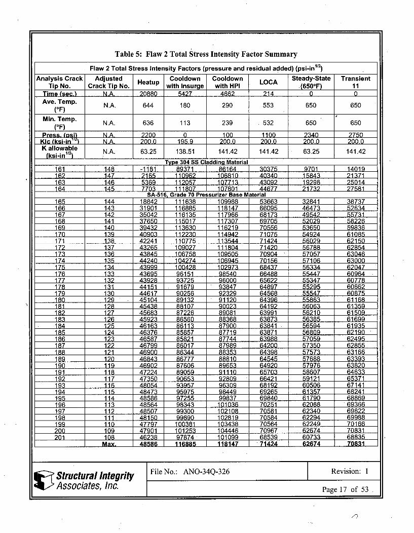
Table 5: Flaw 2 Total Stress Intensity Factor Summary
Flaw 2 Total Stress Intensity Factors (pressure and residual added) (psi-in1/2)
Analysis Crack Adjusted Heatup Cooldown Cooldown LOCA Steady-State TransientTip No. Crack Tip No. with Insurge with HPI ,(650°F) 11
Time (sec.) N.A. 20880 5427 4662 214 0 0Ave. Temp. N.A. 644 180 290 553 650 650
(OF)
Min. Temp. N.A. 636 113 239 532 650 650(OF)
Press. IJs N.A. 2200 0 100 1100 2340 2750KIc (ksi-in N .A. 200.0 195.9 200.0 200.0 200.0 200.0K allowable
(ksi-in112) N.A. 63.25 138.51 141.42 141.42 6325 141.42
Type 304 SS Cladding Material161 148 ,-1181 89371 86164 30375 9701 14019162 147 2165 110962 106810 40340 15843217163 146 5369 112057 107713 4019296 250141_ 4 145 7703 111807 107801 44677 217322
SA-51 Grade 70 Pressurizer Base Material
165 144 18842 1 111638 109988 53663 32841 38737166 143 31901 116885 118147 66095 46473 52634167 142 35042 116135 117966 68173 49542 55731168 141 37650 115017 117307 69705 52029 58226169 140 39432 113630 116219 70556 53650 59836170 139 40903 112230 114942 71075 54924 61085171 138 422411 110775 113544 71424 56029 62150172 137 43265 109027 111804 71420 1 56788 62854173 136 43845 106758 109505 70904 57057 63046174 135 4240 104274 106945 70156 57106 63000175 134 13999 100428 102973 68437 56334 62047176 133 5 96151 98540 66488 55447 60964177 132 43928 93725 96000 65622 55347 60778178 1341 91679 93847 64897 55295 60662179 130 446171 90256 92329 64568 55547 60BZ5180 129 45104 1 89132 91120 64396 55863 61168181 128 45438 1 8107 90023 64192 56063 61359182 127 45683 1 87226 89081 63991 56210 61509183 126 45923 1 86560 88368 63873 56385 61699184 125 46163 1 86113 87900 63841 56594 61935185 124 46376 85857 87719 63871 56809 62190186 123 46587 85821 87744 63988 57059 62495187 122 46799 86017 87989 64200 57350 62855188 121 46900 86344 88353 64398 57573 631661_ 9 120 46843 86777 88810 64545 57688 63393190 119 46902 87606 89653 64920 57976 63820191 118 47224 89059 91110 65703 58607 64633192 117 47350 90653 92809 66421 59121 65371193 116 48054 1 93957 96309 68192 1 60506 67141194 115 48473 95975 98449 69265 61357 68241195 114 48586 97255 99837 69840 61790 68869196 113 48564 98343 101036 70251 62088 69366197 112 48507 99300 102108 70581 62340 69822198 i1l 48150 99890 102819 70584 62294 69988199 110 47797 100381 103438 70564 62249 70166200 109 47901 101253 104446 70967 62674 70831201 108 46238 97874 101099 68539 60733 68835
_ Max. 48586 11885 11J8147 71424 62674 70831
')
Structural IntegrityAssociates, Inc.
7)
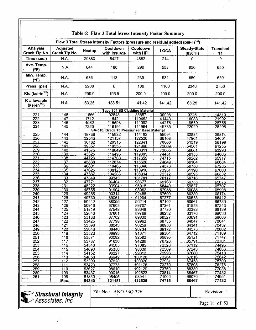
Table 6: Flaw 3 Total Stress Intensity Factor Summary
Flaw 3 Total Stress Intensity Factors (pressure and residual added) (psi-in1/2)
Analysis Adjusted Cooldown Cooldown LOCA Steady-State TransientCrack Tip No. Crack Tip No. Heatup with Insurge with HPI (6500F) 11
Time (sec.) N.A. 20880 5427 4662 214 0 0
Ave. Temp. N.A. 644 180 290 553 650 650(OF)
Min. Temp. N.A. 636 113 239 532 650 650(OF)
Press. (psi) N.A. 2200 0 100 1100 2340 2750
KIc (ksi-in112) N.A. 200.0 195.9 200.0 200.0 200.0 200.0
K allowable(ksi-in112) N.A. 63.25 138.51 141.42 141.42 63.25 141.42
Type 304 SS Cladding Material221 148 -1666 i 92548 8f857 . 998 I 9725 1319222 147 1712 1 115421 110452 1 4143.. 16083 21992223 146 4962. 1 116596 111992 1 44276 4 19630 25756224 145 '7229n I 116194 11164 .4575 1 22020 AS7928299
SA-516, Grade 70 Pressurizer Base Material225 144 18736 11 59329 114193 55094 33534 39874226 143 32546 121157 122520 68108 47961 54601227 142 36182 120316 122341 70600 51519 ,58199228 141 39357 119353 121868 72669 54561 61255229 140 41575 118049 120811 73805 56601 63293230 139 43325 116496 119395 74451 58135 64806231 138 44726 114700 117659 74715 59282 65917232 137 45838 112674 115620 '74649 60104 66684233 .136 46801 110463 113346 74373 60730 67235234 135 47625 108128 110916 73931 61190 67603235 134 47567 104288 106934 72312 60595 66832236 133 47349 99343 101781 70117 59716 65747237 132 47771 96404 98677 69168 59735 65676238 131 48222 93904 96018 68440 59837 65707239 130 48755 91904 93962 67955 60085 65908240 129 49285 90314 92488 67600 60380 66174241 128 49730 89061 91204 67277 60633 66412242 127 50212 88095 90214 67102 60961 66739243 126 50916 87603 89707 67261 61553 67343244 125 51819 87548 89648 67730 62383 68199245 124 52640 87661 89769 68232 63176 69033246 123 53138 87702 89830 68527 63691 69606247 122 53425 87798 89962 68735 64047 70041248 121 53598 88043 90259 68950 64341 70437249 120 53648 88448 90734 69172 64575 70802250 119 53523-.- 88993 91371 69364 64712 71109251 118 53571 90082 92582 69895 65121 71747252 117 53787 91636 94286 70726 65791 72701253 116 54340 94505 97385 '72328 67112 74495254 115 54093 95350 98339 72569 67243 74866255 114 54152 96227 99312 72996 67600 75418256 113 54058 96942 100128 73264 67816 75842257 112 53390 97028 10032L0 72931 67458 75700258 i11 53423 97773 101176 73279 67808 76278259 110 53627 98610 .102199 73760 68330 77038260 109 53437 99016 106232 73814 68467 77432261 108 51330 95405 198941 1 71000 66070 74951
Max, 54I34'0 t 121157 [122520 174715 68467 1 77432
Structural integrity File No.: ANO-34Q-326 Revision: I
Associates, Inc. Page 18 of 53
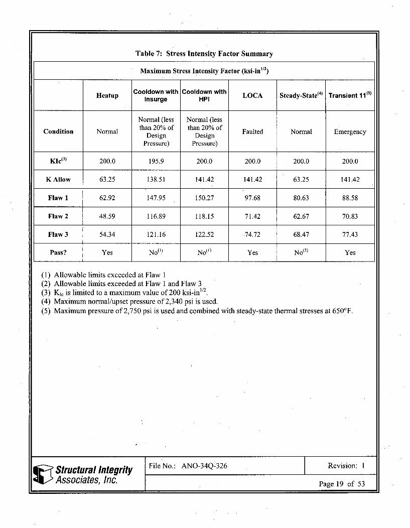
Table 7: Stress Intensity Factor Summary
Maximum Stress Intensity Factor (ksi-in1/ 2)
Heatup Cooldown with Cooldown with LOCA Steady-State(4) Transient 1(s)Insurge HPI
Normal (less Normal (less
Condition Normal than 20% of than 20% of Faulted Normal EmergencyDesign DesignPressure) Pressure)
KIc(3) 200.0 195.9 200.0 200.0 200.0 200.0
K Allow 63.25 138.51 141.42 141.42 63.25 141.42
Flaw 1 62.92 147.95 150.27 97.68 80.63 88.58
Flaw 2 48.59 116.89 118.15 71.42 62.67 70.83
Flaw 3 54.34 121.16 122.52 74.72 68.47 77.43
Pass? Yes NoO,) NoMf) Yes No(2) Yes
(1) Allowable limits exceeded at Flaw 1(2) Allowable limits exceeded at Flaw 1 and Flaw 3(3) Ki, is limited to a maximum value of 200 ksi-in"2.(4) Maximum normal/upset pressure of 2,340 psi is used.(5) Maximum pressure of 2,750 psi is used and combined with steady-state thermal stresses at 650 0F.
Structural Integrity File No.: ANO-34Q-326 Revision: 1
Associates, Inc. Page 19 of 53
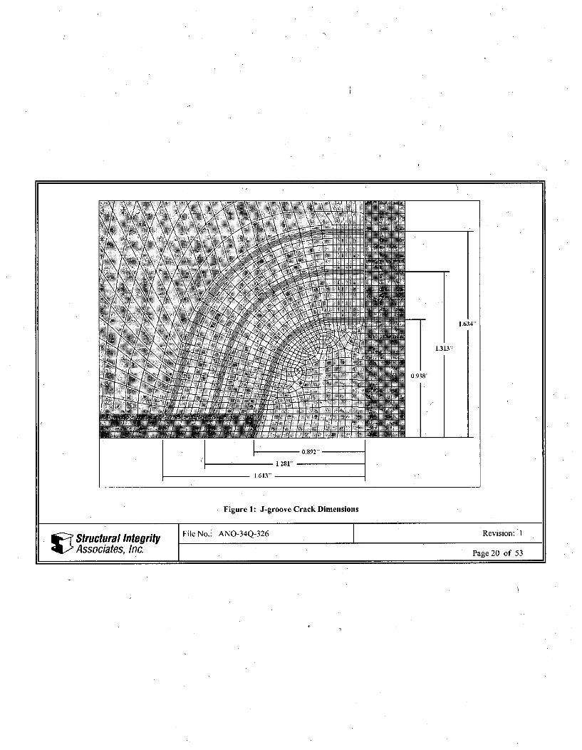
Figure 1: J-groove Crack Dimensions
Structural Integrity File No.: ANO-34Q-326 Revision: 1
Associates, Inc. Page 20 of 53
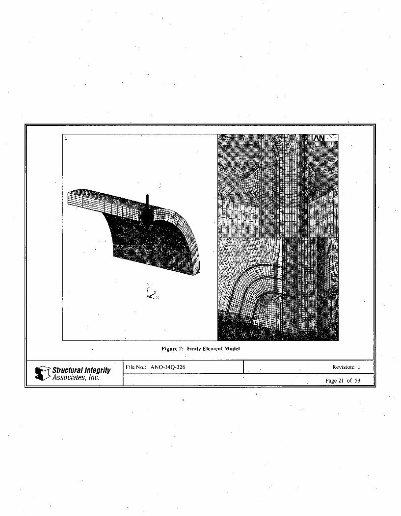
Figure 2: Finite Element Model
Structural Integrity File No.: ANO-34Q-326 Revision: 1
Associates, Inc. Page 21 of 53
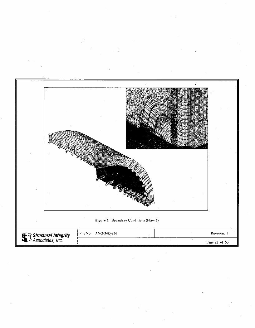
Figure 3: Boundary Conditions (Flaw 3)
Structural Integrity File No.: ANO-34Q-326 Revision: IAssociates, Inc. Page 22 of 53
LEFM analysis using uniform loads
Figure 4: 1,000 psi Uniform Crack Face Pressure (Flaw 3)
Structural Integrity File No.: ANO-34Q-326 Revision: I
Associates, Inc. Page 23 of 53
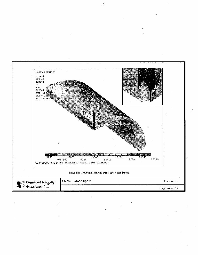
Figure 5: 1,000 psi Internal Pressure Hoop Stress
Structural Integrity File No.: ANO-34Q-326 Revision: I
Associates, Inc. Page 24 of 53
ELEMENTS
TYPE NUM
PR•R -NqROm
-13004 2205 17414-5400 9810 25018
LEFM analysis using imported crack face pressure
3262340228
4783255436
Figure 6: Residual Stress at Crack Face (Flaw 3)
Structural Integrity File No.: ANO-34Q-326 Revision: I
Associates, Inc. Page 25 of 53
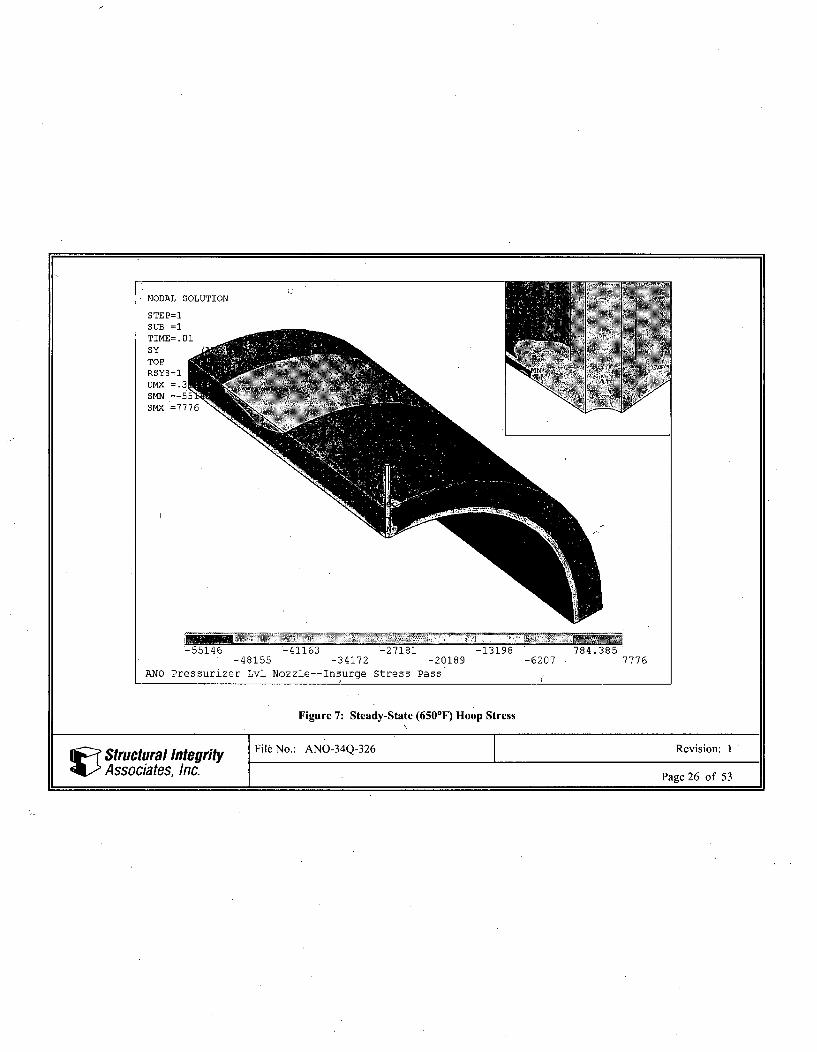
Figure 7: Steady-State (650*F) Hoop Stress
Structural Integrity File No.: ANO-34Q-326 Revision: I1
Associates, Inc. Page 26 of 53
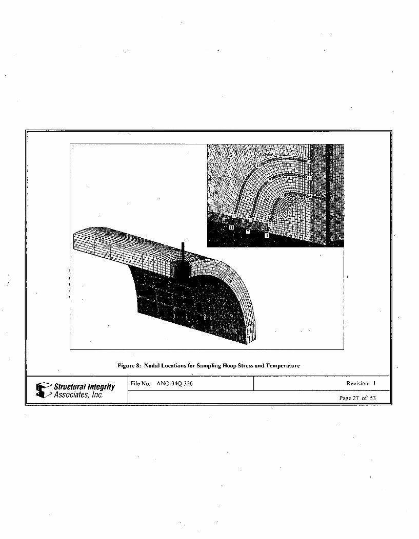
Figure 8: Nodal Locations for Sampling Hoop Stress and Temperature
Structural Integrity File No.: ANO-34Q-326 Revision: 1Associates, Inc. Page 27 of 53
Hoop Stress in J-groove Region (Heatup)
10000
0
-10000
-20000
-30000(nCL00
-40000
-50000
-60000
-70000
-'- Ni
N3----N4
!N5
-'- N6--- N7
-N8-N9
N10.- -N11
N12
--x-- N13- N14
Time (sec)
Figure 9: Hoop Stress History in J-groove Region for Heatup
Structural Integrity File No.: ANO-34Q-326 Revision: I
Associates, Inc. Page 28 of 53
Hoop Stress in J-groove Region (Insurge Cooldown)
200000
150000
100000
0.
CL
0.00
50000
•--- NI
N3•N4
-N5+N6
--- N7-N8
•N9
N10
N12
-- N--N13-•-N 14
0
-50000
-100000
Time (sec)
Figure 10: Hoop Stress History in J-groove Region for Cooldown with Insurge
V Structural IntegrityAssociates, Inc.
Hoop Stress in J-groove Region (HPI)
C.
000
-4-- Ni-0D-N2
N3-. x-N4
-- E- N6
--- N7-N8
N9.......N 10
N12
---- N 13.. * N14
-100000
Time (sec)
Figure 11: Hoop Stress History in J-groove Region for Cooldown with High Pressure Injection (HPI) Test
Structural Integrity File No.: ANO-34Q-326 Revision: I
Associates, Inc. Page 30 of 53
Hoop Stress in J-groove Region (LOCA)
60000
40000
20000
t.
0.0
0
0
-4--'-- Ni1
-- N2
N3
-.- N4•• .- N5
--- N6
•N7
-N8
-N9
N10- -N11
N12
--- N13
-•- N14
-20000
-40000
-60000
Time (sec)
Figure 12: Hoop Stress History in J-groove Region for Loss of Coolant Accident (LOCA)
Structural Integrity File No.: ANO-34Q-326 Revision: I
Associates, Inc. Page 31 of 53
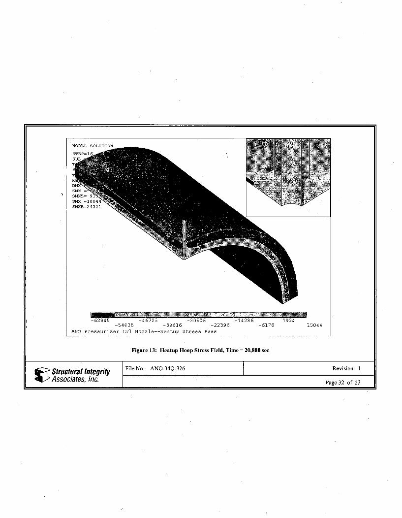
Figure 13: Heatup Hoop Stress Field, Time = 20,880 sec
Structural Integrity File No.: ANO-34Q-326 Revision: 1
Associates, Inc. Page 32 of 53
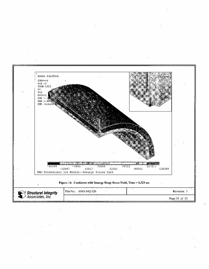
Figure 14: Cooldown with Insurge Hoop Stress Field, Time = 5,323 sec
Structural Integrity File No.: ANO-34Q-326 Revision: 1
Associates, Inc. Page 33 of 53
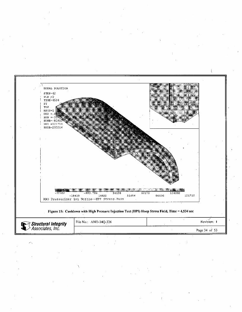
Figure 15: Cooldown with High Pressure Injection Test (HPI) Hoop Stress Field, Time = 4,534 sec
Structural Integrity File No.: ANO-34Q-326 Revision: 1
Associates, Inc. Page 34 of 53
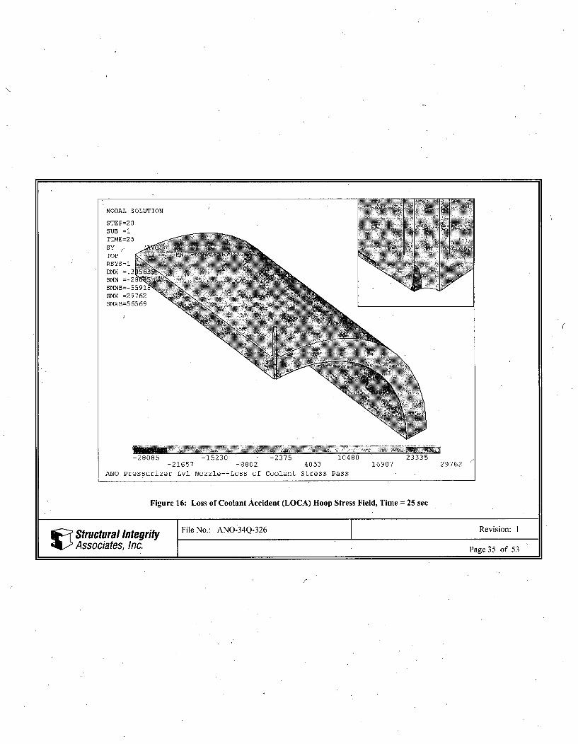
Figure 16: Loss of Coolant Accident (LOCA) Hoop Stress Field, Time = 25 sec
Structural Integrity File No.: ANO- 34Q-326 Revision: 1
Associates, Inc. Page 35 of 53
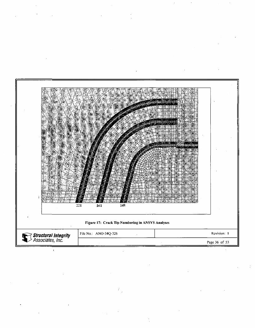
Figure 17: Crack Tip Numbering in ANSYS Analyses
Structural Integrity File No.: ANO-34Q-326 Revision: I
Associates, Inc. Page 36 of 53
1,000 psi Face Pressure
1900
1800 Ai
1700
1600
S1500 ---- Fla-Flw 2
141DO Flaw 3
1300
1200
1100
1000 124100 110 120 130 140 150 160
Crack Tip Location
Note: Refer to Figure 17 for Crack Tip Locations
Figure 18: Crack Face Pressure Stress Intensity Factor
Structural Integrity " File No.: ANO-34Q-326 Revision: I
Associates, Inc. Page 37 of 53
1,000 psi Internal Pressure
21500
19500
17500
15500
S13500-
C -4-Flaw 1
. 11500 MFlaw2
9500 -
7500 -
5500
3500
1500
100 110 120 130 140 150 160
Crack Tip Location
Note: Refer to Figure 17 for Crack Tip Locations
Figure 19: Internal Pressure Stress Intensity Factor
Structural Integrity File No.: ANO-34Q-326 Revision: I
Associates, Inc. Page 38 of 53
Steady State
01(0 110 120 130 140 150 11 0
-5000 -
-10000 -
-15000
-20000
E4-Flaw 1"; -25000 - Flaw 2
-&Flaw 3
-30000
-35000
-40000-
-45000-
-50000
Crack Tip Location
Note: Refer to Figure 17 for Crack Tip Locations
Figure 21: Steady-State (650'F) Stress Intensity Factor
V Structural Integrity File No.: ANO-34Q-326 Revision: IAssociates, Inc. Page 40 of 53
Heatup
-4Flaw I
CL
-40000 •
-50000-
-60000 -
-70000-
Crack Tip Location
Note: Refer to Figure 17 for Crack Tip Locations
Figure 22: Heatup Stress Intensity Factor
Structural Integrity File No.: ANO-34Q-326 Revision: IAssociates, Inc. Page 41 of 53
Insurge Cooldown (Flaw 1)
120000 00 ---.- . .....-.------ .--- . .----.-. ---... . -.-.... .... ........
10 000
-- 0- 5323 00c-0-- 5324 -00.
1- 5361 -00.• 60000 1-5389-
1-5427 -10.•- 5513 soc.
20000
100 110 120 130 140 100 160
Crock 7ip Location
Insurge Cooldown (Flaw 2) Insurga CoIdow (Flaw 3)
100000
80000 8000
70000 7O000F 5323 -a- -5323 100.
z60000 - 53S24-1c 6000D -- 5324 lo- 5361 sac. -1- 5361 soc.
50000 - 09 0000 -1- 5389 -aI-5- SMo c.
j5 - 5427-10. 1- 5427 10.S40000- 3130. 40000 -551310c.
-4• Ma0. -0-•Mao.
30000 3000
20000 20000
10000 10000
100 110 120 130 140 150 160 100 110 120 130 140 150 10
Crack Tip Loc-on Crack Tip LOCado
Figure 23: • Cooldown with Insurge Stress Intensity Factors at Selected Times
V Structural Integrity File No.: ANO-34Q-326 Revision: IAssociates, Inc. Page 42 of 53
HPI (Flaw 1)
=
- 4534 ce.-.- 4042 soc.
-4a79 4e7-- 4639 $0c
_ 4662 oOc-4786-
-0- Ma..
130Crak Tip Locaio
160
HPI (Flaw 2) HPI (Flaw 3)
80000 -Aft
60000
- 50000
-~
-- 4534 So.
- 4542 soc.- 4579 s-c.
- 4639 s-c.- 4662 sec.
-4786 ac.-- Max.
90000
8O000O
4534 wec.
60000 -- 4542 2c-
2 50000 - 4639 cc- 4662 scc
40000 - 478630000 •n-a
20000
10000
00 110 120 130 140 150 160
Crack Tnp LocaU=i
30000
10000
100 110 120 130 . 140
Crack Tip Locadon
150 160
Figure 24: Cooldown with High Pressure Injection Test (HPI) Stress Intensity Factors at Selected Times
I Structural IntegrityAssociates, Inc.
0OCA (Fla 1)
30000
20000A%- -- 100 se..-a129 C.
i1500C0
-214.
-385- s"
0 mac,
110 120 130 140
Crck Tip Locadon
100 160
LOCA (Flaw 2) LOCA (Flaw 3)
11
29sa.
12 9 sec-a-214 sec
-- 32"S"c-- 3858c.0- Ma..
#1298c
a-21 4 acc
-328 888-3855c.-0-Ma..
100 110 120 130
Crack Tip Lccadcn
140 150 160 100 110 120 130
Crack Tip Locauon
140 150 160
Figure 25: Loss of Coolant Accident (LOCA) Stress Intensity Factors at Selected Times
Structural Integrity File No.: ANO-34Q-326 Revision: 1Associates, Inc. Page 44 of 53
Insurge Cooldown
110000
100000
90000800E Flaw 1
-U-Flaw 2-&-Flaw 3
S70000 ________
60000
50000
40000
100 110 120 130 140 150 160
Crack Tip Location
Note: Refer to Figure 17 for Crack Tip Locations
Figure 26: Cooldown with Insurge Maximum Thermal Stress Intensity Factor
Structural Integrity File No.: ANO-34Q-326 Revision: 1
Associates, Inc. Page 45 of 53
HPI
110000
100000-
90000
80000-80000- -4-Flaw 1
-U Flaw 2CL -& Flaw 370000
60000
50000
40000100 110 120 130 140 150 160
Crack Tip Location
Note: Refer to Figure 17 for Crack Tip Locations
Figure 27: Cooldown with High Pressure Injection Test (HPI) Maximum Thermal Stress Intensity Factor
Structural Integrity File No.: ANO-34Q-326 Revision: I
Associates, Inc. Page 46 of 53
LOCA
30000
".
10000
5000
-4-Flaw 1-- Flaw 2-hFlaw 3
00 110 120 130 140 150 160
Crack Tip Location
Note: Refer to Figure 17 for Crack Tip Locations
Figure 28: Loss of Coolant Accident (LOCA) Maximum Thermal Stress Intensity Factor
IC
Structural Integrity File No.: ANO-34Q-326 Revision: I
Associates, Inc. Page 47 of 53
Total Heatup K
~4,I444444'~'- -4Flaw 1Z 30000 Flaw 2
-- Flaw 3;
20000
10000
0-
-10000,
100 110 120 130 140 150 160
Crack Tip Location
Note: Refer to Figure 17 for Crack Tip Locations
Figure 29: Heatup Total Stress Intensity Factor
Structural Integrity File No.: ANO-34Q-326 Revision: 1Associates, Inc. Page 48 of 53
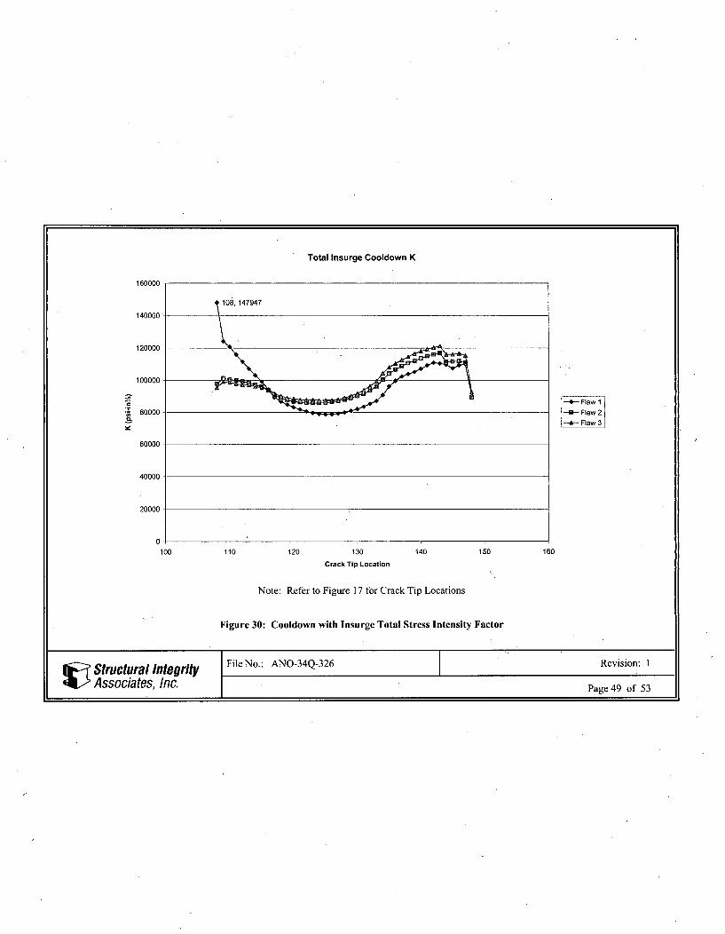
Total Insurge Cooldown K
160000
108,147947
140000
120000
100000
-4Flaw 1"' 80000 B Flaw 2;
-f-Flaw 31
60000
40000
20000-
0100 110 120 130 140 150 160
Crack Tip Location
Note: Refer to Figure 17 for Crack Tip Locations
Figure 30: Cooldown with Insurge Total Stress Intensity Factor
Structural Integrity File No.: ANO-34Q-326 Revision: I
Associates, Inc. Page 49 of 53
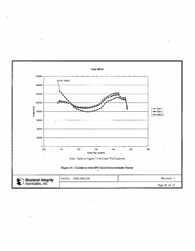
Total HPI K
ýF 14- Flaw 180000 Flaw 2
-A Flaw 3
60000
40000
20000
0.100 110 120 130 140 150 160
Crack Tip Location
Note: Refer to Figure 17 for Crack Tip Locations
Figure 31: Cooldown with HPI Total Stress Intensity Factor
Structural Integrity File No.: ANO-34Q-326 Revision: 1
Associates, Inc. Page 50 of 53
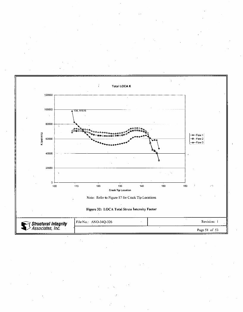
Total LOCA K
120000
100000 97676
80000
-4Flaw 1
60000 -Flaw2C-A Flaw 3
40000
20000
0100 110 120 130 140 150 160
Crack Tip Location
Note: Refer to Figure 17 for Crack Tip Locations
Figure 32: LOCA Total Stress intensity Factor
Structural Integrity File No.: ANO-34Q-326 Revision: 1
Associates, Inc. Page 51 of 53
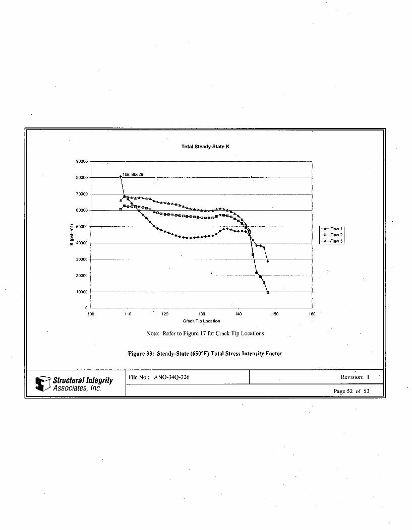
Total Steady-State K
90000-
80000 10880629
70000
60000-
5F40000
30000
20000
10000
0.
100 110 120 130 140 150 160
Crack Tip Location
Note: Refer to Figure 17 for Crack Tip Locations
Figure 33: Steady-State (650 0F) Total Stress Intensity Factor
• Structural Inte grity File No.: ANO-34Q-326 Revision: I
Associates, Inc. Page 52 of 53
7 REFERENCES
1. Structural Integrity Calculation ANO-34Q-303,\Rev. 0, "Pressurizer One-inch Level/Sampling NozzleRepair Finite Element Model."
2. Structural Integrity Calculation ANO-34Q-307, Rev. 0, "Pressurizer level sensing/sampling nozzle (noexisting pad) repair thermal transients/stress analysis."
3. Email from Lawrence Theriault (Entergy) to Gole Mukhim (SI), "Screening of Areva's transients forANO- I BMI MNSA and flaw evaluation," with attachment "CALC-86-E-0074-161.pdf (page 11),"dated December 20, 2005, SI File No. ANO-34Q-207P.
4. Structural Integrity Calculation ANO-34Q-323, Rev. 0, "Pressurizer Level Sensing/Sampling NozzleResidual Stress Analysis."
5. ANSYS Release 8.1 (w/Service Pack 1), ANSYS Inc., June 2004.
6. Anderson, T. L., "Fracture Mechanics Fundamentals and Applications", Second Edition, CRC Press,1995.
8. ASME Boiler and Pressure Vessel Code, Section XI, 1998 Edition with Addenda through 2000.
10. PVP2005-71718, Proceedings of PVP2005, 2005 ASME Pressure Vessels and Piping DivisionConference, "Technical Basis for Revised Flaw Acceptance Criteria under IWB-3610 of ASMESection XI," July 17-21, 2005, Denver, Colorado USA.
11. Structural Integrity Calculation ANO-34Q-3 11, Rev. 0, "Pressurizer Level Sensing/Sampling Nozzle(no existing pad) Repair Mechanical Loads Analysis."
12. Structural Integrity Calculation ANO-34Q-302, Rev. 0, "Pressurizer Thermowell Repair Finite ElementModel Development and Unit Pressure Test."
Structural Integrity File No.: ANO-34Q-326 Revision: 1
Associates, Inc. Page 53 of 53
r-
APPENDIX A
ANSYS FILENAME LISTING
Structural Integrity File No.: ANO-34Q-326 Revision: 1
Associates, Inc. Page Al of A3
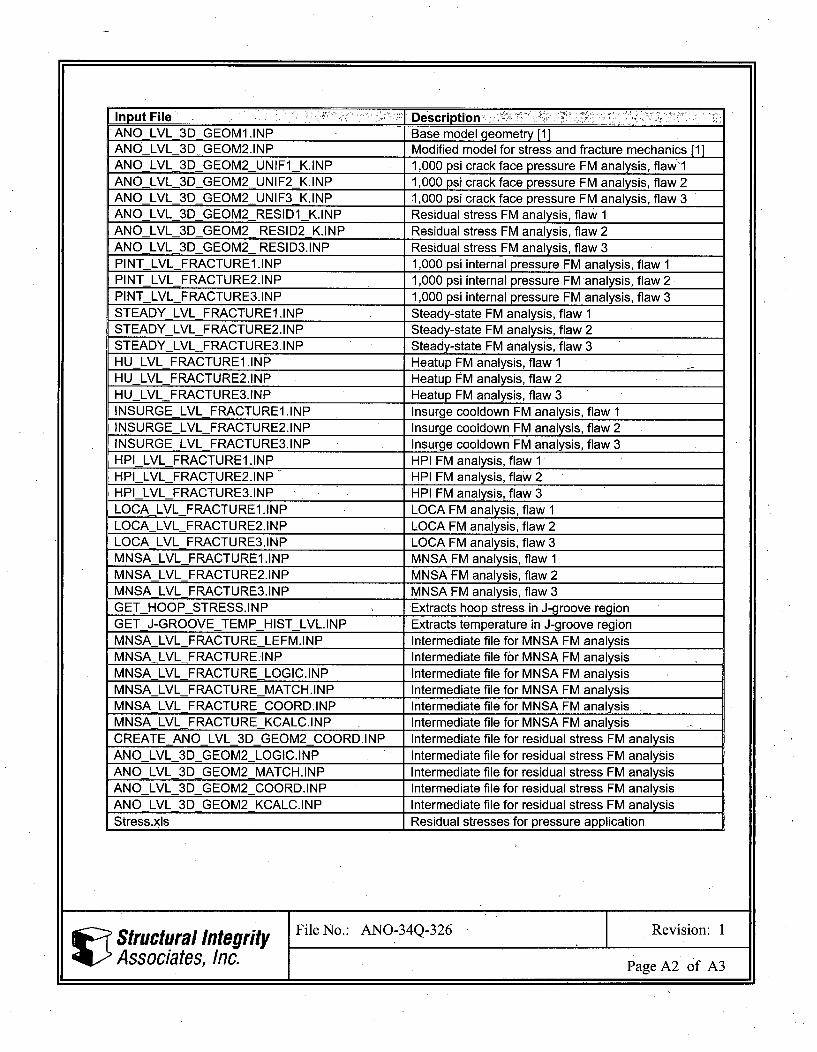
Input File I DescriptionANO LVL 3D GEOM1 .INP Base model geometry [1]ANO LVL 3D GEOM2.INP Modified model for stress and fracture mechanics [1]ANO LVL 3D GEOM2 UNIFI K.INP 1,000 psi crack face pressure FM analysis, flaw"1ANO LVL 3D GEOM2 UNIF2 K.INP 1,000 psi crack face pressure FM analysis, flaw 2ANO LVL 3D GEOM2 UNIF3 K.INP 1,000 psi crack face pressure FM analysis, flaw 3ANOLVL 3D GEOM2_RESIDI K.INP Residual stress FM analysis, flaw 1ANO LVL 3D GEOM2 RESID2 K.INP Residual stress FM analysis, flaw 2ANOLVL 3D GEOM2 RESID3.INP Residual stress FM analysis, flaw 3PINT LVL FRACTUREI.INP 1,000 psi internal pressure FM analysis, flaw IPINT LVL FRACTURE2.1NP 1,000 psi internal pressure FM analysis, flaw 2PINT LVL FRACTURE3.INP 1,000 psi internal pressure FM analysis, flaw 3STEADYLVL_FRACTURE1.INP Steady-state FM analysis, flaw 1STEADY LVL FRACTURE2.INP Steady-state FM analysis, flaw 2STEADY LVL FRACTURE3.INP Steady-state FM analysis, flaw 3HU LVL FRACTURE1 .INP Heatup FM analysis, flaw 1HU LVL_FRACTURE2.INP Heatup FM analysis, flaw 2HULVL FRACTURE3.INP Heatup FM analysis, flaw 3INSURGE LVL_FRACTURE1 .INP Insurge cooldown FM analysis, flaw 1INSURGELVL_FRACTURE2.INP Insurge cooldown FM analysis, flaw 2INSURGELVLFRACTURE3.INP Insurge cooldown FM analysis, flaw 3HPI LVLFRACTURE1 .INP HPI FM analysis, flaw 1HPI LVL_FRACTURE2.INP HPI FM analysis, flaw 2HPI LVLFRACTURE3.INP HPI FM analysis, flaw 3LOCA LVL_FRACTURE1.INP LOCA FM analysis, flaw 1LOCALVL_FRACTURE2.INP LOCA FM analysis, flaw 2LOCALVL FRACTURE3.INP LOCA FM analysis, flaw 3MNSALVL FRACTUREI.INP MNSA FM analysis, flaw 1MNSA LVLFRACTURE2.INP MNSA FM analysis, flaw 2MNSA LVL FRACTURE3.INP IMNSA FM analysis, flaw 3GET HOOP STRESS.INP Extractshoop stress in J-groove regionGET J-GROOVE TEMPHIST LVL.INP Extracts temperature in J-groove regionMNSA LVL FRACTURE LEFM.INP Intermediate file for MNSA FM analysisMNSA LVL FRACTURE.INP Intermediate file for MNSA FM analysisMNSALVL FRACTURE LOGIC.INP Intermediate file for MNSA FM analysisMNSALVLFRACTUREMATCH.INP Intermediate file for MNSA FM analysisMNSA LVL FRACTURE COORD.INP Intermediate file for MNSA FM analysisMNSA LVL FRACTURE KCALC.INP Intermediate file for MNSA FM analysisCREATEANOLVL_3D GEOM2 COORD.INP Intermediate file for residual stress FM analysisANO LVL 3D GEOM2 LOGIC.INP Intermediate file for residual stress FM analysisANO LVL 3D GEOM2 MATCH.INP Intermediate file for residual stress FM analysisANOLVL 3D GEOM2 COORD.INP Intermediate file for residual stress FM analysisANO LVL 3D GEOM2 KCALC.INP Intermediate file for residual stress FM analysisStress.xls Residual stresses for pressure application
Structural Integrity File No.: ANO-34Q-326 Revision: 1
Associates, Inc. Page A2 of A3
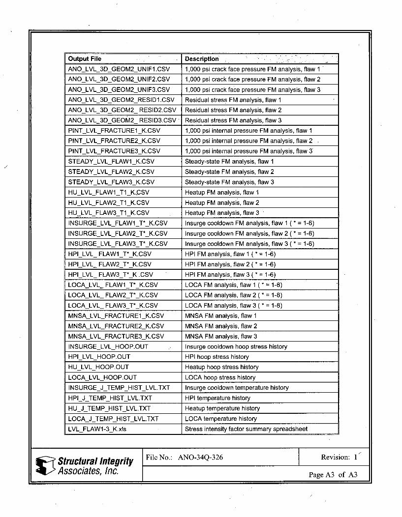
Output File Description.
ANOLVL 3D GEOM2_UNIFI.CSV 1,000 psi crack face pressure FM analysis, flaw 1
ANOLVL 3DGEOM2_UNIF2.CSV 1,000 psi crack face pressure FM analysis, flaw 2
ANOLVL_3DGEOM2_UNIF3.CSV 1,000 psi crack face pressure FM analysis, flaw 3
ANOLVL_3DGEOM2_RESID1.CSV Residual stress FM analysis, flaw 1
ANOLVL_3DGEOM2_ RESID2.CSV Residual stress FM analysis, flaw 2
ANOLVL 3DGEOM2_ RESID3.CSV Residual stress FM analysis, flaw 3
PINTLVLFRACTUREI_K.CSV 1,000 psi internal pressure FM analysis, flaw 1
PINTLVLFRACTURE2_K.CSV 1,000 psi internal pressure FM analysis, flaw 2
PINTLVL_FRACTURE3_K.CSV 1,000 psi internal pressure FM analysis, flaw 3
STEADYLVLFLAWIK.CSV Steady-state FM analysis, flaw 1
STEADYLVLFLAW2_K.CSV Steady-state FM analysis, flaw 2
STEADYLVLFLAW3_K.CSV Steady-state FM analysis, flaw 3
HULVLFLAW1 Ti K.,CSV Heatup FM analysis, flaw 1
HULVLFLAW2_TiK.CSV Heatup FM analysis, flaw 2
HULVLFLAW3_Ti K.CSV Heatup FM analysis, flaw 3
INSURGELVLFLAW1_T*_K.CSV Insurge cooldown FM analysis, flaw 1 ( * = 1-6)
INSURGELVLFLAW2_T*_K.CSV Insurge cooldown FM analysis, flaw 2 ( * = 1-6)
INSURGELVLFLAW3_T*_K.CSV Insurge cooldown FM analysis, flaw 3 ( * = 1-6)
HPILVL_ FLAW1_T*_K.CSV HPI FM analysis, flaw 1 (* = 1-"6)
HPILVL_ FLAW2_T*_K.CSV HPI FM analysis, flaw 2 (* = 1-6)
HPILVL_ FLAW3 T* K_.CSV HPI FM analysis, flaw 3 (* = 1-6)
LOCALVL_ FLAW1_T*_K.CSV LOCA FM analysis, flaw 1 (* = 1-8)
LOCALVL_ FLAW2_T*_K.CSV LOCA FM analysis, flaw 2 (* = 1-8)
LOCALVL_ FLAW3_T*_K.CSV LOCA FM analysis, flaw 3 (* = 1-8)
MNSALVLFRACTURE1_K.CSV MNSA FM analysis, flaw 1
MNSALVLFRACTURE2_K.CSV MNSA FM analysis, flaw 2
MNSALVLFRACTURE3_K.CSV MNSA FM analysis, flaw 3
INSURGELVLHOOP.OUT Insurge cooldown hoop stress history
HPILVLHOOP.OUT HPI hoop stress history
HULVL HOOP.OUT Heatup hoop stress history
LOCALVLHOOP.OUT LOCA hoop stress history
INSURGEJTEMPHISTLVL.TXT Insurge cooldown temperature history
HPI J TEMPHISTLVL.TXT HPI temperature history
HU J TEMPHISTLVL.TXT Heatup temperature history
LOCAJ TEMPHISTLVL.TXT LOCA temperature history
LVLFLAW1-3_K.xls Stress intensity factor summary spreadsheet
Structural Integrity File No.: ANO-34Q-326 Revision: 1
Associates, Inc. Page A3 of A3