revision #24 july 23rd, 2015 grand ... - lib.store.yahoo.net · toll free 1-888-658-1658...
TRANSCRIPT
Outdoor Living Today www.outdoorlivingtoday.com [email protected]
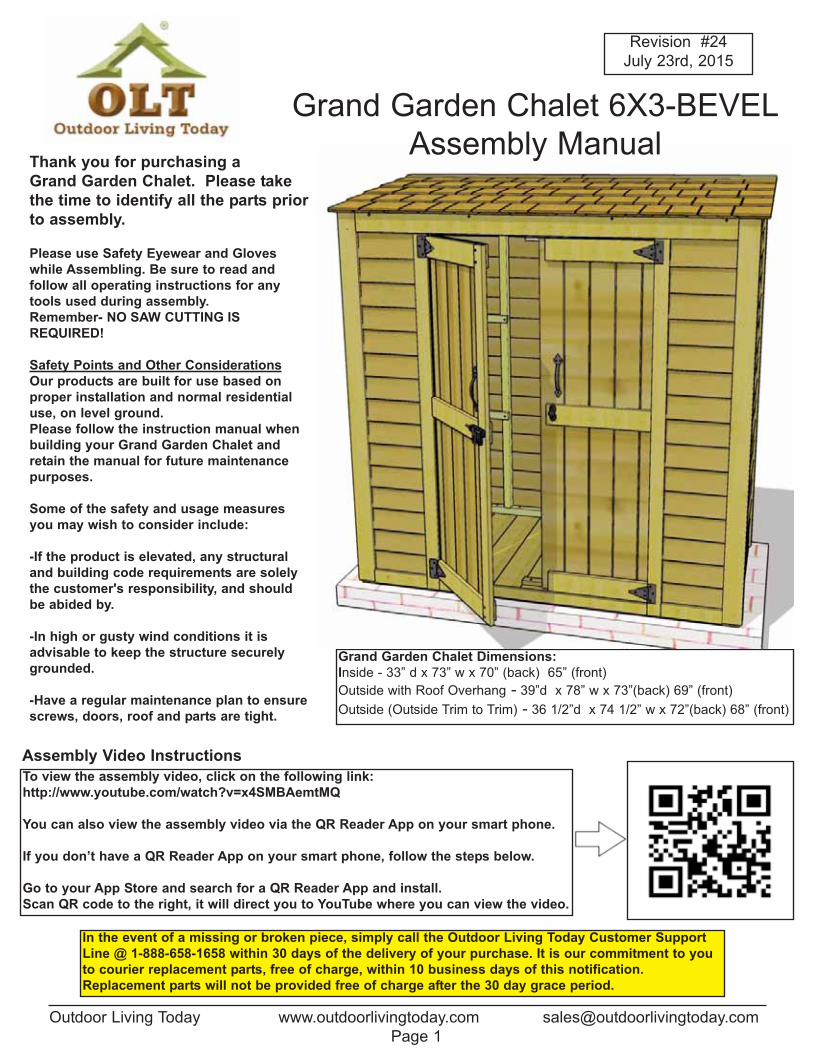
Grand Garden Chalet Dimensions:
Inside - 33” d x 73” w x 70” (back) 65” (front)
Outside with Roof Overhang - 39”d x 78” w x 73”(back) 69” (front)
Outside (Outside Trim to Trim) - 36 1/2”d x 74 1/2” w x 72”(back) 68” (front)
Thank you for purchasing a
Grand Garden Chalet. Please take
the time to identify all the parts prior
to assembly.
Please use Safety Eyewear and Gloves
while Assembling. Be sure to read and
follow all operating instructions for any
tools used during assembly.
Remember- NO SAW CUTTING IS
REQUIRED!
Safety Points and Other Considerations
Our products are built for use based on
proper installation and normal residential
use, on level ground.
Please follow the instruction manual when
building your Grand Garden Chalet and
retain the manual for future maintenance
purposes.
Some of the safety and usage measures
you may wish to consider include:
-If the product is elevated, any structural
and building code requirements are solely
the customer's responsibility, and should
be abided by.
-In high or gusty wind conditions it is
advisable to keep the structure securely
grounded.
-Have a regular maintenance plan to ensure
screws, doors, roof and parts are tight.
Grand Garden Chalet 6X3-BEVEL
Assembly Manual
Page 1
Revision #24
July 23rd, 2015
In the event of a missing or broken piece, simply call the Outdoor Living Today Customer Support
Line @ 1-888-658-1658 within 30 days of the delivery of your purchase. It is our commitment to you
to courier replacement parts, free of charge, within 10 business days of this notification.
Replacement parts will not be provided free of charge after the 30 day grace period.
To view the assembly video, click on the following link:
http://www.youtube.com/watch?v=x4SMBAemtMQ
You can also view the assembly video via the QR Reader App on your smart phone.
If you don’t have a QR Reader App on your smart phone, follow the steps below.
Go to your App Store and search for a QR Reader App and install.
Scan QR code to the right, it will direct you to YouTube where you can view the video.
Assembly Video Instructions
Toll Free 1-888-658-1658 www.outdoorlivingtoday.com [email protected]
Page 2
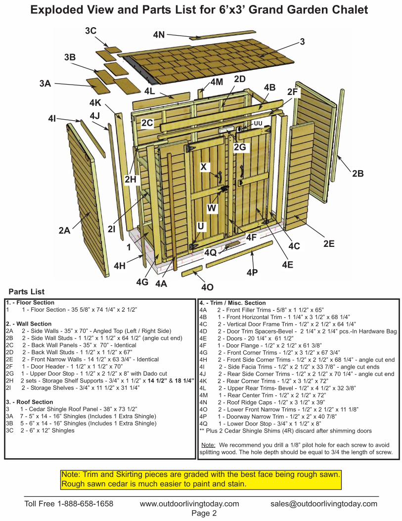
1. - Floor Section
1 1 - Floor Section - 35 5/8” x 74 1/4” x 2 1/2”
2. - Wall Section
2A 2 - Side Walls - 35” x 70” - Angled Top (Left / Right Side)
2B 2 - Side Wall Studs - 1 1/2” x 1 1/2” x 64 1/2” (angle cut end)
2C 2 - Back Wall Panels - 35” x 70” - Identical
2D 2 - Back Wall Studs - 1 1/2” x 1 1/2” x 67”
2E 2 - Front Narrow Walls - 14 1/2” x 63 3/4” - Identical
2F 1 - Door Header - 1 1/2” x 1 1/2” x 70”
2G 1 - Upper Door Stop - 1 1/2” x 2 1/2” x 8” with Dado cut
2H 2 sets - Storage Shelf Supports - 3/4” x 1 1/2” x 14 1/2” & 18 1/4”
2I 2 - Storage Shelves - 3/4” x 11 1/2” x 31 1/4”
3. - Roof Section
3 1 - Cedar Shingle Roof Panel - 38” x 73 1/2”
3A 7 - 5” x 14 - 16” Shingles (Includes 1 Extra Shingle)
3B 5 - 6” x 14 - 16” Shingles (Includes 1 Extra Shingle)
3C 2 - 6” x 12” Shingles
4. - Trim / Misc. Section
4A 2 - Front Filler Trims - 5/8” x 1 1/2” x 65”
4B 1 - Front Horizontal Trim - 1 1/4” x 3 1/2” x 68 1/4”
4C 2 - Vertical Door Frame Trim - 1/2” x 2 1/2” x 64 1/4”
4D 2 - Door Trim Spacers-Bevel - 2 1/4” x 2 1/4” pcs.-In Hardware Bag
4E 2 - Doors - 20 1/4” x 61 1/2”
4F 1 - Door Flange - 1/2” x 2 1/2” x 61 3/8”
4G 2 - Front Corner Trims - 1/2” x 3 1/2” x 67 3/4”
4H 2 - Front Side Corner Trims - 1/2” x 2 1/2” x 68 1/4” - angle cut end
4I 2 - Side Facia Trims - 1/2” x 2 1/2” x 33 7/8” - angle cut ends
4J 2 - Rear Side Corner Trims - 1/2” x 2 1/2” x 70 1/4” - angle cut end
4K 2 - Rear Corner Trims - 1/2” x 3 1/2” x 72”
4L 2 - Upper Rear Trims- Bevel - 1/2” x 4 1/2” x 32 3/8”
4M 1 - Rear Center Trim - 1/2” x 2 1/2” x 72”
4N 2 - Roof Ridge Caps - 1/2” x 3 1/2” x 39”
4O 2 - Lower Front Narrow Trims - 1/2” x 2 1/2” x 11 1/8”
4P 1 - Doorway Narrow Trim - 1/2” x 2” x 40 7/8”
4Q 1 - Lower Door Stop - 3/4” x 1 1/2” x 8”
** Plus 2 Cedar Shingle Shims (4R) discard after shimming doors
Note: We recommend you drill a 1/8” pilot hole for each screw to avoid
splitting wood. The hole depth should be equal to 3/4 the length of screw.
Exploded View and Parts List for 6’x3’ Grand Garden Chalet
Parts List
Note: Trim and Skirting pieces are graded with the best face being rough sawn.
Rough sawn cedar is much easier to paint and stain.
1
2A
4I2C
4N
4H 4E
3
4J
2D
4F2I
4B
2H
2E
2F3A
4A
UU
X
W
2B
3B
3C
4G4O
2G
4K
4M
4C
4L
4P
4Q
U
6x3 GRAND GARDEN CHALET
2 1/2”
Note: screws and nails shown actual size.
3/4”
2”
3/4”
1 1/2”
7/8”
(U) Tee Hinge
x 4 pcs.(X) Door Handle
x 2 pcs.
Black Headed Screw
Black Headed Screw
Finishing
Shingle
Square Drive Bit
Hardware Kit (Provided)
Safety Glasses Work Gloves
Safety Equipment Required (Not Provided)
Ladder
Screw Gun/Drill Tape MeasureHammer Wood Clamp
Level Pliers
Tools Required (Not Provided)
(BB) Silver
Barrel Bolt
Toll Free 1-888-658-1658 www.outdoorlivingtoday.com [email protected]
(W) Barrel Bolt
Silver
Page 3
1/8” & 3/8” Drill Bits
1 1/2”
Black Headed Bolt with Silver Nut and Washer
1 1/4”
C
H
E
G
J
K
M
FF
DD
(UU) 1/2”x 2 3/4”
Plywood Spacer
3/8” Wrench
1” F
(4D) 2 1/4”x 2 1/4”
Door Trim Spacer

1. Lay Chalet Floor Section (1) (35 5/8” x 74 1/4”)
on a level foundation only. Patio Stones or a
Concrete Slab both make excellent foundations. Use
a level to confirm and shim floor joists as required.
Toll Free 1-888-658-1658 www.outdoorlivingtoday.com [email protected]
Page 4
Each wall is
marked with a
color dot on frame
to show top up.
3. Center Studs on each wall and attach with
1 - 2 1/2” Screw (C) per end. Flip walls over.
Due to packaging constraints,
center wall studs must be attached
prior to erecting walls.
You can find the Square Drive
Bit for the screws in with the
Hardware Kit Bag (DD).
2. Locate both Side Wall Panels (2A) (left
and right side panels) and 2 Side Wall
Studs (2B) (1 1/2” x 1 1/2” x 64 1/2). Side
Wall Studs are angle cut on 1 end. Lay on a
flat level surface with frames up. Locate Back
Wall Panels (2C) and Back Wall Studs (2D)
(1 1/2” x 1 1/2” x 67”). The top framing of
both back walls are angle cut. Lay on flat level
surface.
Back Wall
Top Framing
angle cut
Back Wall
Stud (2D)
Sid
eS
tud
Side Wall Stud
angle cut on top.
4. Using a tape measure or chalk line as a nailing line,
attach wall studs to siding with 1 - 1 1/2” Finishing Nail (K)
per piece of siding. Nail into thick part of siding (butt). Skip
bottom and top siding pieces. Complete all stud attachments
now.
2 1/2”
screw
Cente
rStu
d
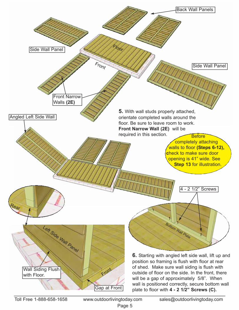
Front
Gap at Front
5. With wall studs properly attached,
orientate completed walls around the
floor. Be sure to leave room to work.
Front Narrow Wall (2E) will be
required in this section.
Left SideW
all Panel
Wall Siding Flush
with Floor.
Toll Free 1-888-658-1658 www.outdoorlivingtoday.com [email protected]
Page 5
Front
Back Wall Panels
Side Wall Panel
Front Narrow
Walls (2E)
Floor
Angled Left Side Wall
Side Wall Panel
6. Starting with angled left side wall, lift up and
position so framing is flush with floor at rear
of shed. Make sure wall siding is flush with
outside of floor on the side. In the front, there
will be a gap of approximately 5/8”. When
wall is positioned correctly, secure bottom wall
plate to floor with 4 - 2 1/2” Screws (C).
Rear
4 - 2 1/2” Screws
BottomWall Plate
Before
completely attaching
walls to floor (Steps 6-12),
check to make sure door
opening is 41” wide. See
Step 13 for illustration.

Toll Free 1-888-658-1658 www.outdoorlivingtoday.com [email protected]
Page 6
BackW
allPanel
Rear Corner
Back Wall
Angled Left Side Wall
7. With your helper holding the side wall panel, position a Back Wall Panel (2C) in rear corner.
Important: Align Wall Siding Flush with Floor Framing.
Wall Siding flush
with outside floor
8. When side and back walls are aligned in corner correctly, wall framings with be offset. Screw wall
framings together with 3 - 2 1/2” Screws (C). Secure bottom wall plate to floor with 4 - 2 1/2” screws (C).
Optional - Caulking
seams will help prevent
moisture from entering
at seam. Caulking not
included in kit.
Left
Sid
eW
all
Back Wall top
plate angle cut
2 1/2”
screw
5/8” offset
2 1/2”
screw
Toll Free 1-888-658-1658 www.outdoorlivingtoday.com [email protected]
Page 7
9. Position 2nd Back Wall Panel (2C) on Floor as per Step 8. Attach wall frames together at top, middle
and bottom with 3 - 2 1/2” screws. Secure bottom wall plate to floor with 4 - 2 1/2” Screws (C).
Right Side
Angled Wall
Panel
Back Wall
Panel
10. In the corner, align and attach right Side Wall (2A) framing to back wall framing as per
Steps 7 & 8. Secure bottom wall plate of side wall to floor with 4 - 2 1/2” Screws (C).
Expert Advise - If you’re placing the
shed tight up against a fence or wall,
you may consider attaching the Rear
Corner and Center Trim (4H & 4J) on
Back Wall seam first. See Step 38.
Attach both Back Walls together,
secure Rear Center Trim, then attach
Side Wall Panel.
2 1/2”
screw
Gap at Front with bottom
of wall siding flush with
outside of floor.

Toll Free 1-888-658-1658 www.outdoorlivingtoday.com [email protected]
Page 8
11. Locate Front Narrow Walls (2E) and position wall framing flush with side wall framing in corner.
Make sure narrow wall is positioned right side up.
Front Narrow Wall (2E)
Wall Framings Flush
12. Align butt or bottom of wall siding flush with outside of floor
framing. When correctly positioned, secure bottom wall plate to
floor with 2 - 2 1/2” Screws (C). Attach vertical wall framings
together at top, middle and bottom with 3 - 2 1/2” Screws (C).
Wall Siding Flush
with Floor Framing.
Before attaching,
make sure door
opening is 41” wide.
See Step 13.
13. Align and attach the second front narrow
wall panel as per Step 12.
14. Locate Door Header (2F) (1 1/2” x 1 1/2” x 70”)
and place on top of front narrow wall framings.
Door
Header (2F)
Side Wall
2 1/2”
screw
41” Wide

Toll Free 1-888-658-1658 www.outdoorlivingtoday.com [email protected]
Page 9
17. When all walls are attached together, check
door width at top and bottom. Door width should
be 41” wide. If required, loosen narrow and side
wall plate screws, adjust door width and re-secure.
There can be an 1/8” tolerance in the width but top
and bottom width should be the same.
16. Attach Upper Door Stop (2G). Dado cut
aligned to the front. Center on door header and
attach with 2 - 2 1/2” Screws (C). Screw down
from the header into Stop. Use Clamp to hold stop.
Upper Door Stop with Dado
Cut to front. Part (2G)
2 - 2 1/2”
screws.
41”
18. Storage Shelf positioning is flexible so decide what height configuration suits your needs. Gather your
Storage Shelf Supports (2H). The short Support (14 1/2”) attaches to the narrow wall, the long (18 1/4”)
to the back wall. Position using a Level, and drill Pilot Holes to prevent ends of Supports from splitting.
Attach first Support using 2 - 1 1/4” Screws (E). Place Storage Shelf on attached Support, Level, and
mark position of 2nd Support. Pilot Hole and secure 2nd Support.
Storage Shelf Support (2H)
15. With door header positioned evenly on narrow wall top plates and flush against side wall top framing,
secure using 6 - 2 1/2” Screws (C) screwing down from the top of door header down into the upper narrow
wall plates. Have your helper push side walls against end of door header to achieve tight fit if possible.
Door HeaderNarrow Wall
Top Plate
Storage Shelf (2I)
2 1/2” screws
Back Wall Side Wall

6”
21. Place and attach (3B) Shingle (6” wide) directly on top of Shingle (3A). Shingle (3B) will slide
under 2nd row shingle. Secure with 2 - 7/8” Shingle Nails (M) 8” from butt.
6” Wide Shingle (3B)
Slide under
1/4” gap
Nail 8”
fromButt
Nailing Line
Flush with (3A) Shingle
5” Shingle (3a)
Toll Free 1-888-658-1658 www.outdoorlivingtoday.com [email protected]
Page 10
19. Place Storage Shelf (2I) on top of supports and secure with 4 - 1 1/2” Finishing Nails (K).
Complete 2nd Shelf (if desired) as per Steps 18 & 19.
5”
20. Lay Roof Panel (3) on flat level ground. Note, overhanging Outside Shingles have been removed to avoid
shipping damage and need to be installed. Locate (3A , 3B & 3C) Shingles. There are 6 - 5” wide x 16” long
(3A) Shingles, 4 - 6” wide x 16” long (3B) Shingles and 2 - 6” wide x 12” long (3C) Shingles. Position and
attach (3A) Shingle (5” wide) on roof panel with 2 - 7/8” Shingle Nails (M). See above for details.
16”
long
Roof Panel (3)
Outside Shingles
must be installed
Nail 4” from
front of shingle.
1/4” gap
Align Roof
Panel so thick
end of Shingle
(butt end) is
facing front.
See Step 25
for shingle
layout.
Front
Thin end
Thick end
5”
6”
22. Place and attach second (3A) Shingle (5” wide) in line with 2nd row of shingles. Shingle (3A)
will partially cover shingle (3B). Secure with 2 - 7/8” Shingle Nails (M) 8” from butt.
23. Place and attach 2nd (3B) Shingle (6” wide) in line with 3rd row of shingles. Shingle (3B) will partially
cover shingle (3A). Secure with 2 - 7/8” Shingle Nails (M) 8” from Butt. Complete attachment of 3rd 5”
wide (3A) shingle.
Toll Free 1-888-658-1658 www.outdoorlivingtoday.com [email protected] 11
2nd Row of Shingles
8”from
Butt
1/4” gap
2nd (3A) Shingle
2nd 6” wide
(3B) Shingle
5”
3rd 5” wide
(3B) Shingle
2nd 6” wide
(3B) Shingle
3rd 5” wide
(3A) Shingle
6”
24. To finish end, place and attach (3C) shingle (6” wide x 12” long) in line with 5th and final row of
shingles. Shingle (3C) will partially cover shingle (3B). Secure with 2 - 7/8” Shingle Nails (M) 10”
from butt.
12” Long
Shingle (3C)
10” FromButt

26. Lift up completed cedar shingle roof panel and place on upper wall framing. In the front, align
plywood roofing 1/8” back from door header. On the side, plywood should be flush with side wall
siding. Equally space roof from side-to-side. In the rear, plywood should sit on back wall top plate.
Plywood Roofing flush
with Side Wall Siding
25. Complete attachment of shingles on opposite side of roof panel following Steps 20-24.
Toll Free 1-888-658-1658 www.outdoorlivingtoday.com [email protected]
Page 12
3A 3B
3B
3A
3C
Completed Roof Panel (3)
Fron
t
Front
3A
Door Header
Rear
1/8” Set-back

Toll Free 1-888-658-1658 www.outdoorlivingtoday.com [email protected]
Page 13
27. From inside the shed, start securing the roof by screwing the door header into Roof Panel on an
angle with 3 - 2 1/2” Screws (C). Make sure screw tips do not go completely through roof panel. On the
sides and rear, screw from upper framing into Roof Panel. Use 2 screws per each wall panel. Screw on
an angle and make sure screw tips do not go completely through roof panel.
28. Locate 2 Front Filler Trims (4A) (1 1/2” x 5/8” x 65”).
Filler trim will be covered by corner trim in Step 37. Attach in
each front corner with 6 - 1 1/2” Finishing Nails (K).
29. Locate Front Horizontal Trim (4B)
(3 1/2” x 1 1/4” thick at top x 68 1/4”). Position horizontal trim tight up underneath roofpanel. From side-to-side evenly space. Securewith 6 - 2 1/2” Screws (C) into door header.
Front Horizontal Trim (4B)
3/4” thick with additional bevel
attached to back - Thick side up
2 1/2” Screws

32. Locate Doors (4E- 2 identical) and Door Flange (4F) (1/2” x 2 1/2” 61 3/8”). Orientate Doors so the
outside of each door is facing up and the pre-drilled holes located in each corner are positioned to the
outside. Locate Black T- Hinges (U). Attach each hinge to door as above with 1 - 1 1/2” Black Headed
Bolt (FF), and a 1/4” Silver Nut, using a 3/8” wrench. Finish hinge by securing with 2 - 3/4” Black Headed
Screws (J). Drill small pilot holes first to prevent wood from splitting. Complete both doors(4 Hinges).
30. Locate 2 Vertical Door Frame Trims (4C) (1/2” x 2 1/2” x 64 1/4”). Position on front
narrow wall flush with outside of wall framing and tight underneath front horizontal trim. Attach with
1 - 1 1/2” Finishing Nail (K) on second piece of wall siding into the butt (where trim and siding touch).
Flush with
wall framing
1 nail into butt of 2nd
piece of wall siding.
31. Locate 2 Door Trim Spacers (4D) found in the Hardware
Bag with Plywood Spacer (UU). Slide door spacer between
door trim and wall siding. Attach with 1 - 1 1/2” Finishing Nail
(K). Nail through trim and into spacer. Complete attachment of
door trim using 4 more 1 1/2” Finishing Nails (K). Make sure
to align trim accordingly. Complete both sides.
1/4” Silver Nut
and washer
1 1/2” Bolt
3/4” black
head screws
Door Flange
(4F)
Left Door Right Door
Toll Free 1-888-658-1658 www.outdoorlivingtoday.com [email protected]
Page 14
Drill Pilot Holes to
prevent splitting.
Only one nail until spacer
attached on Step 31.
Refer to Step 43 before attaching
door trim and do a dry run.
Toll Free 1-888-658-1658 www.outdoorlivingtoday.com [email protected]
Page 15
33. Flip left door over to attach Door Flange
(4F). Push flange tight against horizontal door
trim. Attach with 6 - 1” Silver Screws (F ).
Position flange tight against horizontal door trim
and even with trim on top and bottom. If out
slightly, make sure top horizontal trim and flange
are even. Pre-drill with 1/8” bit to prevent wood
from splitting.
34. Starting with right door first, lift and position door in opening. Leave a 1/8” gap on right side and 1/4”
gap on the bottom. Use a Shim Shingle (4R) to shim the door at bottom to help position door
evenly. When door is aligned correctly, screw hinge into vertical door frame trim with 1 - 2” Black
Headed Screws (H). Use only 1 screw initially per hinge until both door alignments are confirmed. Drill
pilot holes to prevent wood from splitting.
1/8”
gap
35. Position left side door (with flange) as per Step 34. Once again, use only 1 - 2” Black Headed
Screw (H) per hinge initially to secure door to vertical door frame trim.
Left Side Door.
1/4” gap
1 - 2” screw per
Hinge initially.
Left Door Right Door
Hor. Door Trim flush with
Outside/ gap Inside
6 - 1” Screws.
Pre-drill to
prevent splitting.
Flip Left Door Over.
Door Flange
(4F).
Rear Side
Door
Flange

38. Continuing around the shed, place a Side Facia Trim (4I) angle cut both ends (1/2” x 2 1/2” x
33 7/8”) tight against front side corner trim and snug underneath roof panel. Attach side facia into
side wall cleats with 4 - 1 1/2” Finishing Nails (K).
Toll Free 1-888-658-1658 www.outdoorlivingtoday.com [email protected]
Page 16
36. With both Doors partially attached, check
to see doors open and close correctly. Make
any necessary adjustments and when
satisfied, completely secure hinges to vertical
door frame trim with two more 2” Black
Headed Screws (H) per hinge. Drill pilot
holes to prevent wood from splitting.
37. Locate a Front Corner Trim (4G) (1/2” x 3 1/2” x 67 3/4”) (1 for each front side), and Front Side
Corner Trim (4H) angle cut 8 deg. at top (1/2” x 2 1/2” x 68 1/4”). Angled side trim pieces are unique to
each corner and are attached rough side out. Starting in one corner, position both trims up tight
underneath roof shingles. Align front corner trim tight against horizontal door trim. Front corner trim will
cap front side corner trim. When correctly aligned, attach each piece with 6 - 1 1/2” Finishing Nails (K).
Front Side
Corner Trim (4H)
2 1/2” wide.
Angle cut 8 deg.
at top
Front Corner Trim (4G)
3 1/2” wide.
Expert Advice:
Do a dry run with front and rear corner
trims before attaching. Confirm the rough
face is configured correctly and small trim
gaps are satisfactory before attaching.
2 more - 2” screw
per Hinge
Hor. Trim
Tight
Note: Trim pieces are graded with the best face
being rough. Rough sawn cedar is much easier to
paint and stain and is the industry standard.
Tight
Sid
eT
rim
Side Facia

Toll Free 1-888-658-1658 www.outdoorlivingtoday.com [email protected]
Page 17
39. Locate a Rear Side Corner Trim (4J) angle cut 8 deg. at top (1/2” x 2 1/2” x 70 1/4”) and Rear
Corner Trim (4K) (1/2” x 3 1/2” x 72”). Once again, angled side trim pieces are unique to each corner
and are attached rough side out. Position side trim tight underneath side facia. Align rear corner trim tight
underneath roof shingles. Side trim will cap rear trim. Attach each pieces with 6 - 1 1/2” Finishing Nails (K).
Locate Upper Rear Trim - Bevel Siding (4L) (4 1/2” x 32 3/8”). Align tight against rear corner trim and
underneath roof. Attach with 4 - 1 1/2” Finishing Nails (K).
Rear Corner
Trim (4K)
Rear Side
Corner Trim
(4J) -angle cut
8 deg. at top.
41. Complete other rear corner, side and front corner trims as per Steps 37 - 39.
Rear Center
Trim (4M)
Upper Rear
Trim (4L)
40. Locate Rear Center Trim (4M)
(1/2” x 2 1/2” x 72”). Align tight
against upper rear trim and
underneath roof. Attach with
6 - 1 1/2” Finishing Nails (K).
Side Trim overlaps
Rear Trim

42 Using a Step Ladder, place both Roof Ridge Caps (4N) (1/2” x 3 1/2” x 39”) on rear row of roof shingles.
Ridge Caps will overhang shingles by 1/4”. Attach each piece with 4 - 1 1/2” Finishing Nails (K).
Roof Ridge
Caps (4N)
Toll Free 1-888-658-1658 www.outdoorlivingtoday.com [email protected]
Page 18
44. Attach Door Handles (X) to doors
with 3 - 3/4” Black Headed Screws (J)
per handle. Choose desired handle height.
Make sure screws go into interior door
framing and are not exposed on inside.
45. Attach Black Barrel Bolt (W) as illustrated above with
6 - 3/4” Black Headed Screws (J).
Note: Female part of barrel bolt is positioned higher than
male. Do a dry run first to position barrel bolt correctly.
Important - Drill pilot holes with 1/8” drill bit prior to secur-
ing with screws to prevent wood splitting.
43. Locate both Lower Front Narrow Trims (4O) (1/2” x 2 1/2” x 11 1/8”) and Doorway Narrow
Trim (4P) (1/2” x 2” x 40 7/8”). Place narrow wall trims between door trim and front corner trim flush
with bottom of trims. Attach each with 2 - 1 1/2” Finishing Nails. Place lower door trim between door
trims flush with bottom. Attach with 4 - 1 1/2” Finishing Nails (K).
4O
4O4P
Flush
Important: Drill shallow Pilot
Holes to prevent splitting.

47. Install the Barrel Bolt Plywood Spacer (UU) to
interior door frame, flush at the bottom, and 1/4” from
edge, as pictured. Use 2 - 1 1/4” Screws (E) to secure.
Mark door
stop.
46. Attach Lower Door Stop (4Q)
(3/4” x 1 1/2” x 8”) to floor with 2 - 1 1/4”
Screws (E). To align correctly, close door,
mark, and attach. Drill pilot holes first to
prevent wood from splitting.
Toll Free 1-888-658-1658 www.outdoorlivingtoday.com [email protected]
Page 19
48. Position the Interior Silver Barrel Bolt (BB) on the plywood spacer and attach with 4 - 3/4” Silver
Screws (G). Tap barrel bolt with hammer on underside of interior door stop to mark location.
49. Open door and drill out marked barrel bolt impression with a 3/8” Drill Bit. Close door, slide
barrel bolt in drilled hole to confirm fit.
UUInterior Door Frame
BB
G
We hope your experience constructing our 6x3 Grand Garden Chalet has been both positive and
rewarding. We value your feedback and would like to hear back from you on how well we are doing
in the following areas:
1. Customer Service
2. On Time Shipping
3. Motor Freight Delivery
4. Quality of Materials
5. Assembly Manual
6. Overall Satisfaction.
Please call, write or email us at:
Page 20
Congratulations on assembling
your 6x3 Grand Garden Chalet!
Note: Our Sheds are shipped as
an unfinished product. If exposed
to the elements, the Western Red
Cedar lumber will weather to a
silvery-gray color. If you prefer to
keep the cedar lumber looking
closer to the original color, we
suggest that you treat the wood
with a good oil base wood stain.
You may also wish to paint your
new shed rather than stain it. In
both cases we recommend that
you consult with a paint and stain
dealer in your area for their
recommendations.
The materials contained in this Assembly
Manual may be downloaded or copied
provided that ALL copies retain the
copyright and any other proprietary
notices contained on the materials. No
material may be modified, edited or
taken out of context such that its use
creates a false or misleading statement
or impression as to the positions,
statements or actions.
Canadian Address9393 287th StreetMaple Ridge, British ColumbiaCanada V2W 1L1
United States AddressP.O. Box 96Sumas, WashingtonUSA 98295
Toll Line: 1.888.658.1658 | Fax: 1.604.462.5333 | [email protected]