revision history sheet the information on this document is
TRANSCRIPT

P.S NO. : PS/445/2677 PURCHASE SPECIFICATION REV. NO: 00 GROUP: VFD ENGINEERING A4 – 12 PAGE 00 OF 24
REVISION HISTORY SHEET
REV. DATE NATURE OF CHANGE REASONS PREPARED BY APPROVED BY NO.
00 09-11-2020 FIRST ISSUE ------
REVISION 00 APPROVED BY L SUBBALAKSHMI
PREPARED BY ISSUED BY DATE
KAMALINI DEY VFD ENGG 09-11-2020
CO
PYR
IGH
T A
ND
CO
NFI
DEN
TIA
L Th
e in
form
atio
n on
this
doc
umen
t is t
he p
rope
rty o
f BH
AR
AT
HEA
VY
ELE
CTR
ICA
LS L
IMIT
ED.
It m
ust n
ot b
e us
ed d
irect
ly o
r ind
irect
ly in
any
way
det
rimen
tal t
o th
e in
tere
st o
f the
com
pany
.

P.S NO. : PS/445/2677 PURCHASE SPECIFICATION REV. NO: 00 GROUP: VFD ENGINEERING A4 – 10 PAGE 01 OF 24
REVISION 00 APPROVED BY L SUBBALAKSHMI
PREPARED BY ISSUED BY DATE
KAMALINI DEY VFD ENGG 09-11-2020
CO
PYR
IGH
T A
ND
CO
NFI
DEN
TIA
L Th
e in
form
atio
n on
this
doc
umen
t is t
he p
rope
rty o
f BH
AR
AT
HEA
VY
ELE
CTR
ICA
LS L
IMIT
ED.
It m
ust n
ot b
e us
ed d
irect
ly o
r ind
irect
ly in
any
way
det
rimen
tal t
o th
e in
tere
st o
f the
com
pany
.
TECHNICAL SPECIFICATION OF IGBT BASED VFD FOR SQUIRREL CAGE INDUCTION MOTOR FOR
BOILER FEED PUMP (BFP)
1. Project Details
Sl. No. Parameter Specification
1 Project Location JHAGADIA, BHARUCH, GUJARAT, INDIA
2 PROJECT 1 x 120 MW COAL BASED REHEAT TPP
3 CUSTOMER DCM SHRIRAM LTD.
4 CONSULTANT DEVELOPMENT CONSULTATIONS PVT.
LTD. (DCPL)
2. Environment Specifications
Sl. No. Parameter Specification 1 Maximum Ambient
Temperature 50 C
2 Minimum Ambient
Temperature 12C
3 Equipment Design
Temperature
(IS-9676)
50C
4 Relative Humidity 95%
5 Altitude Less than 1000 M above MSL
6 Seismic Zone Zone III as per IS : 1893 Part-1
8 Environment Polluted and Corrosive
9 Location of VFD panels Indoor, Air conditioned room

P.S NO. : PS/445/2677 PURCHASE SPECIFICATION REV. NO: 00 GROUP: VFD ENGINEERING A4 – 10 PAGE 02 OF 24
REVISION 00 APPROVED BY
L SUBBALAKSHMI
PREPARED BY ISSUED BY DATE
KAMALINI DEY VFD ENGG 09-11-2020
CO
PYR
IGH
T A
ND
CO
NFI
DEN
TIA
L Th
e in
form
atio
n on
this
doc
umen
t is t
he p
rope
rty o
f BH
AR
AT
HEA
VY
ELE
CTR
ICA
LS L
IMIT
ED.
It m
ust n
ot b
e us
ed d
irect
ly o
r ind
irect
ly in
any
way
det
rimen
tal t
o th
e in
tere
st o
f the
com
pany
.
3. Input and Transformer Data
Sl. No.
Parameter Specification
1 System Voltage / Frequency /Ph
11kV / 50Hz / 3
2 Voltage Variation +/-10% 3 Frequency Variation +/- 5% 4 Combined Voltage and
Frequency Variation +10%
5 Fault Level 50KA for 1 sec 6 Transformer Type Dry type integrated Transformer (In Vendor scope) 7 Rating Transformer must be designed to carry 110%
current of calculated VFD rating. Transformer sizing calculation shall be provided along with offer.
8 Power Cables Cable termination to be provided by the vendor for Transformer HV side cable termination suitable for 1Rx3Cx300 sqmm, 11kV, Al, XLPE cable. The exact sizes will be intimated during drawing approval stage. Cables, glands and termination kits in Customer /BHEL scope.
4. Motor Data
Sl. No.
Parameter Specification
1 Type Squirrel Cage Induction Motor
2 Scope Manufactured by BHEL-Bhopal
3 Rated Output 2200 kW, 2990 RPM 4 Rated Voltage and
Current 11 kV, 133 A
5 No load current 34 A 6 Fed from Variable Frequency Drive (V/f Control) with Bypass 7 Duty Class Continuous - S1 8 Efficiency and Power
Factor:
% of Load Efficiency Rated PF 50 94.5 0.91 75 95.5 100 95.8

P.S NO. : PS/445/2677 PURCHASE SPECIFICATION REV. NO: 00 GROUP: VFD ENGINEERING A4 – 11 PAGE 03 OF 24
CO
PYR
IGH
T A
ND
CO
NFI
DEN
TIA
L Th
e in
form
atio
n on
this
doc
umen
t is t
he p
rope
rty o
f BH
AR
AT
HEA
VY
ELE
CTR
ICA
LS L
IMIT
ED.
It m
ust n
ot b
e us
ed d
irect
ly o
r ind
irect
ly in
any
way
det
rimen
tal t
o th
e in
tere
st o
f the
com
pany
.
Sl. No.
Parameter Specification
9 Power Cables Cable termination to be provided by the vendor for VFD Output side cable termination suitable for 1Rx3Cx300 sqmm, 11kV, Al, XLPE cable. The exact sizes will be intimated during drawing approval stage. Cables, glands and termination kits in Customer /BHEL scope.
5. Scope:
Sl. No.
Scope of Supply Description
1 a) Fully Assembled Units of 11kV VFD Panels (IGBT/SGCT/IGCT), Air Cooled with integrated Dry type transformer. b) All interconnecting cables between the VFD and integrated Transformer. c) Local Control Station (LCS) mounted near motor (in safe area) for each VFD.
d) VFD Output Isolator (Motorised) .
e) Cable glands and lugs for LCS (Weather proof).
f) Any special cable other than power and control cables from VFD to other equipment. g) Any special tools and tackles h) Laptop (1 No.)
The vendor shall be responsible for engineering and functioning of the complete VFD system, meeting the intent and requirement of this specification & Customer specification. This shall include but not be limited to inverter sizing, transformer sizing, transformer impedance selection, vector group, input and output harmonic filter design and sizing, output dv/dt filter sizing, adequacy of motor cable size selected by BHEL etc. All necessary interlocks as required for safe and reliable operation of VFD system along with Input breaker, Output Isolator and Bypass breaker shall be provided in VFD system. If any special arrangement is required in Input breaker and output isolator, same shall be informed by the vendor in the offer. The machine shall normally run on VFD. In case of drive mal-operation, the motor could be taken on bypass control manually, while the drive could be attended independently. All other control and protections not included in owner’s scope but required for vendors supplied system shall be in vendor’s scope.

P.S NO. : PS/445/2677 PURCHASE SPECIFICATION REV. NO: 00 GROUP: VFD ENGINEERING A4 – 11 PAGE 04 OF 24
CO
PYR
IGH
T A
ND
CO
NFI
DEN
TIA
L Th
e in
form
atio
n on
this
doc
umen
t is t
he p
rope
rty o
f BH
AR
AT
HEA
VY
ELE
CTR
ICA
LS L
IMIT
ED.
It m
ust n
ot b
e us
ed d
irect
ly o
r ind
irect
ly in
any
way
det
rimen
tal t
o th
e in
tere
st o
f the
com
pany
.
6. VFD Specifications
Sl. No
Parameter Specification
1 Drive VFD for BFP 2 Input Voltage From Integrated dry type Transformer 3 Power/Torque vs Speed Torque α Speed2 , Power α Speed3 4 Single Line Diagram See Attachment 3-661-00-00978 5 Output Voltage of VFD 0 to 11kV (V/F = Constant) 6 Output Current of VFD 133 Amps at 50C (Design Ambient) 7 Output Frequency 0 to 50Hz , Resolution: +/- 0.01% under transient
conditions; +/- 0.5% under steady state conditions 8 Overload capacity 115% of rated current for 1 minute at rated voltage
9 Speed Regulation & Speed Accuracy
As per attached Customer Specification
10 Drive Control Sensorless Vector Control 11 Braking Operation Not Applicable 12 Output LC Sinusoidal
Filter Motor is designed for PWM operation. Distance between VFD and Motor is ~200 meters. Vendor to clarify and offer output Filter, if required.
13 VFD Panel Construction
a) Protection Class: IP42 b) Panel: Free standing, floor mounting type,
comprising of rigid welded structural frames with Cold Rolled Sheet Steel enclosure of minimum thickness 2 mm for load bearing and 1.6 mm for other members. All doors and removable covers shall have neoprene gaskets. Ventilating louvers shall have easily removable and washable dust filters.
c) Cooling: Forced Air Cooled VFD should be considered. Cooling system shall include well dimensioned panel, adequate cooling air flow path. Vendor shall ensure that the panel dimensions and flow paths have been designed for continuous running at the specified ambient without overheating. Vendor to provide low noise redundant cooling fan for the VFD panels. The fans shall have 100% redundancy with provision for autostart of standby fan as per attached Customer Specification. Changeover scheme shall be submitted along with the offer. Suitable thermal switch for exit air temperature monitoring shall also be incorporated.
d) Earth Bus – minimum 50*6 mm Copper.

P.S NO. : PS/445/2677 PURCHASE SPECIFICATION REV. NO: 00 GROUP: VFD ENGINEERING A4 – 11 PAGE 05 OF 24
2.9 2.9
CO
PYR
IGH
T A
ND
CO
NFI
DEN
TIA
L Th
e in
form
atio
n on
this
doc
umen
t is t
he p
rope
rty o
f BH
AR
AT
HEA
VY
ELE
CTR
ICA
LS L
IMIT
ED.
It m
ust n
ot b
e us
ed d
irect
ly o
r ind
irect
ly in
any
way
det
rimen
tal t
o th
e in
tere
st o
f the
com
pany
.
Sl. Parameter Specification
13 VFD Panel Construction e) Busbar Material – Electrolytic grade Copper, colour coded. Sleeving/shrouding for safety purposes shall be done.
f) Door Interlock: The VFD shall have a door interlock for safety. This interlock system should ensure that none of the power cabinets can be opened until the main source of power is disconnected or will cause the main source of power to trip. Additionally the same interlock system should ensure that power cannot be initialized to the drive unless the doors are closed. Suitable shrouding mechanism shall be provided so that the DC capacitors cannot be touched till their voltage is zero.
g) Painting: 2 Coats of Primer and 2 Coats of Finish Paint to be given for all surfaces of enclosure. Paint shall be Epoxy Based with Powder Coated Finish – Battle ship grey IS:632 as per IS-5. Paint Thickness: 60 Microns (minimum). Exact paint shade will be confirmed during drawing approval stage.
h) Power and Control Wiring shall be done with Fire retardant (FRLS) cables.
i) Height of the terminal from cable gland plate shall be adequate to take care of the cable sizes and quantity mentioned. Minimum space for the power cable termination shall be 600mm clear from the cable gland plate. Cable entry will be from bottom only. Gland Plates shall be blank (undrilled) – to be drilled at site. Gland Plates shall be minimum 4 mm thick Aluminium (steel not allowed). Gland plate shall be of sufficient strength to handle all the cables.
j) All electronic modules and components shall be accessible from front of panel only. Modular assemblies for both the system control electronic equipment and power electronic equipments shall be used.
k) All low voltage compartment and cabling shall be electrically and physically separated from the high voltage compartment.
l) Lugs for all control cables shall be terminated in terminal block itself. This would avoid usage of different types of lugs at site during commissioning.
m) 20% spare terminals shall be provided.
14 Noise Level Shall be less than 85dB at a distance of 1 metre from the outline of VFD Panels at a height of 1.8 metres from the floor with all the fans running in the VFD Panels.

P.S NO. : PS/445/2677 PURCHASE SPECIFICATION REV. NO: 00 GROUP: VFD ENGINEERING A4 – 11 PAGE 06 OF 24
CO
PYR
IGH
T A
ND
CO
NFI
DEN
TIA
L Th
e in
form
atio
n on
this
doc
umen
t is t
he p
rope
rty o
f BH
AR
AT
HEA
VY
ELE
CTR
ICA
LS L
IMIT
ED.
It m
ust n
ot b
e us
ed d
irect
ly o
r ind
irect
ly in
any
way
det
rimen
tal t
o th
e in
tere
st o
f the
com
pany
.
Sl. No.
Parameter Specification
15 Storage Temperature -40C to +60 C
16 Vibration According to IEC68-2-6
17 Interference According to IEC801 parts 2,3,4 Immunity: The panels shall be designed so as to have low Radio Frequency Interference (RFl) and Electromagnetic Interference (EMl).
18 VFD Efficiency Shall be min 95%. Exact value to be specified by the Vendor.
19 Duty Cycle Class I Duty Cycle as per IEC 146-1
20 VFD Requirements a) Input Choke: Input chokes to be provided, if necessary.
b) Local/Remote: Selector switch shall be provided for operator to select type of operation: Local – Operation from VFD Panel for Speed Control from door mounted interface; Remote – Operation from DCS/LCS. If VFD is set for speed reference from Remote, it shall be possible to program the VFD to either shutdown, go to minimum speed or continue operation at its last known speed reference point whenever a loss of speed reference is detected.
c) Local Start/Stop Push Button to be provided either on Panel door or on keypad.
d) Door Mounted Lockable Push-Button with cover to be provided with 2NO + 2 NC contact for Emergency Stop. One normally open and close contact to be wired to Terminal Block for external Interlocking / Annunciation.
e) Every Panel shall be provided with CFL illumination Lamp with limit switch and MCB. Space heater shall be provided in panel with switch fuse and variable setting thermostat. 240V power socket with MCB shall be provided.

P.S NO. : PS/445/2677 PURCHASE SPECIFICATION REV. NO: 00 GROUP: VFD ENGINEERING A4 – 11 PAGE 07 OF 24
CO
PYRI
GH
T A
ND
CO
NFI
DEN
TIA
L Th
e in
form
atio
n on
this
doc
umen
t is t
he p
rope
rty o
f BH
AR
AT
HEA
VY
ELE
CTR
ICA
LS L
IMIT
ED.
It m
ust n
ot b
e us
ed d
irect
ly o
r ind
irect
ly in
any
way
det
rimen
tal t
o th
e in
tere
st o
f the
com
pany
.
Sl. No.
Parameter Specification
20 VFD Requirements f) 230V, 1phase, 50Hz (exact rating during drawing approval stage) Power Supply to the motor space heater shall be derived from VFD. Necessary interlocking arrangement for this supply shall also be made available in the VFD panels.
g) Vendor to clearly mention the dimension of VFD and Isolator Panel alongwith panel clearances in the technical offer.
h) PLC: PLC shall be provided for Interlocking and Protection (if required)
i) The expected life time of the drive system shall be minimum 20 years. The system including all individual components forming part of the system shall have an availability of minimum 0.997 and a minimum MTBF of 4 years.
j) Any special requirement regarding CT/ PT, protection relay or any other device, in input breaker, which is required for functioning of VFD system shall be considered by the VFD vendor in their scope.
21 VFD Features a) Soft Start and Auto Restart b) Auto Speed Search Facility (Catch on Fly) shall be
available for starting into rotating loads. c) Power loss ride through (Kinetic Buffering) and for
voltage dips over 20% or Power interruption for less than 2 secs.
d) Automatic VFD tuning during start-up. e) Flux optimisation function shall be provided to reduce
the total energy consumption and noise level in case drive is operated below nominal load.
f) Selectable reverse run prohibition g) Adjustable motor overload feature h) Settable minimum and maximum operating frequency i) VFD shall produce not greater than 1% torque
pulsation to the shaft of driven equipment. j) Field adjustable Torque limits and acceleration and
deceleration ramps k) Accelerate / Decelerate Times to be specified. l) Four (4) user programmable preset speeds. m) Earthing scheme should be provided by the vendor.

P.S NO. : PS/445/2677 PURCHASE SPECIFICATION REV. NO: 00 GROUP: VFD ENGINEERING A4 – 11 PAGE 08 OF 24
CO
PYRI
GH
T A
ND
CO
NFI
DEN
TIA
L Th
e in
form
atio
n on
this
doc
umen
t is t
he p
rope
rty o
f BH
AR
AT
HEA
VY
ELE
CTR
ICA
LS L
IMIT
ED.
It m
ust n
ot b
e us
ed d
irect
ly o
r ind
irect
ly in
any
way
det
rimen
tal t
o th
e in
tere
st o
f the
com
pany
. Sl. Parameter Specification 21 VFD Features n) The equipment may be stored outdoors for long
periods before installation. The packing should also be suitable for outdoor storage areas with heavy rains / high ambient temperatures.
o) Vendor shall certify readiness of system fit for commissioning. Vendor’s scope shall also include supply of all specialized tools and tackles required.
p) VFDs shall be installed in Air-conditioned area but it shall be suitable for operation in non-air-conditioned area also.
q) Any special cable other than power and control cables required to connect VFD to other equipment shall be in vendor scope.
r) All electronic PCBs/Modules must have conformal coating to take care of site conditions.
22 Controls and monitoring a) VFD shall be with an interactive and user-friendly door mounted digital operator interface with LCD display and sealed membrane type keypad.
b) The operator interface shall be used for drive programming, drive monitoring and drive trouble shooting. The operator interface must also be able to start and stop the drive, reset VFD faults and manually adjust the VFD's speed reference.
c) The operator interface shall have LED indicators for drive fault, drive run, and drive in current limit.
d) The operator interface shall allow monitoring of inverter operating conditions including speed, current, voltage, torque, power etc.
e) Messages shall be alphanumeric in nature. All the fault messages shall be in English.
f) Provision shall be made available for remote operation.
g) The operator interface shall be able to display all real time operating variables and all drive programming parameters.
h) The operator interface shall be capable of displaying a specific user selected parameter on power-up. This power-up parameter would typically be a parameter that is important to the operator such as motor speed or motor load
i) The following Control signals must be provided: 1) Local/Remote 2) Emergency stop 3) Trip/Close Input breaker

P.S NO. : PS/445/2677 PURCHASE SPECIFICATION REV. NO: 00 GROUP: VFD ENGINEERING A4 – 11 PAGE 09 OF 24
COPY
RIG
HT
AN
D C
ON
FID
ENTI
AL
The
info
rmat
ion
on th
is do
cum
ent i
s the
pro
perty
of B
HA
RA
T H
EAV
Y E
LEC
TRIC
ALS
LIM
ITED
. It
mus
t not
be
used
dire
ctly
or i
ndire
ctly
in a
nyw
ay d
etrim
enta
l to
the
inte
rest
of t
he c
ompa
ny.
Sl. No.
Parameter Specification
22 Controls and monitoring These are indicative. Vendor to suggest the interlocking scheme using these and other outputs as required for the system during detailed Engineering. These Outputs shall be provided with individual relay having 3 changeover potential free contacts wired to terminal blocks. j) All VFD operating parameter shall be stored in
nonvolatile memory. k) The drive shall have built in monitoring of following
parameters as minimum on its digital operator interface and these parameter shall also be displayed at Plant DCS through Modbus link:
i) Input & Output Frequency ii) Input & Output Current iii) Motor Speed iv) Input & Output Voltage v) DC Bus Voltage vi) Input & Output Power vii) Digital Input Status viii) Digital Output Status ix) Analog Input x) Drive Thermal state xi) Motor energy meter xii) Hour run xiii) Transformer Temperature for alarm & trip
l) Necessary transducer shall be provided with 4-20mA output for indicating Motor Speed and Motor Current in the DCS. Transducers shall be capable of driving 500 ohms load.
m) The following indications shall be provided on the VFD Panel Door/ Keypad: i) Motor Running/ VFD ON ii) Motor Stopped/Tripped iii) AC Mains ON iv) Auxiliary Control Supply ON v) VFD Ready vi) VFD Fault vii) External Fault viii) Emergency Stop Activated ix) Motor Overspeed x) Input Breaker Trip xi) Motor zero speed xii) Rectifier output ’ON’ xiii) Transformer winding temperature alarm & trip.
n) The VFD shall store fault logs of minimum last 10
faults in memory.

P.S NO. : PS/445/2677 PURCHASE SPECIFICATION REV. NO: 00 GROUP: VFD ENGINEERING A4 – 11 PAGE 10 OF 24
COPY
RIG
HT
AN
D C
ON
FID
ENTI
AL
The
info
rmat
ion
on th
is do
cum
ent i
s the
pro
perty
of B
HA
RA
T H
EAV
Y E
LEC
TRIC
ALS
LIM
ITED
. It
mus
t not
be
used
dire
ctly
or i
ndire
ctly
in a
nyw
ay d
etrim
enta
l to
the
inte
rest
of t
he c
ompa
ny.
Parameter Specification
22 Controls and Monitoring k) The drive shall have built in monitoring of following parameters as minimum on its digital operator interface and these parameter shall also be displayed at Plant DCS through Modbus link: i) Output Frequency ii) Output Current iii) Motor Speed iv) Output Voltage v) DC Bus Voltage vi) Motor Winding Temperature vii) Output Power (It shall be possible to display power output of the drive in kW) viii) Digital Input Status ix) Digital Output Status x) Analog Input Status xi) Drive Thermal state xii) Motor energy meter xiii) Hour run l) Necessary transducer shall be provided with 4-20 mA output for indicating Motor Speed and Motor Current in the DCS. Transducers shall be capable of driving 500 ohms load. m) The following indications shall be provided on the VFD Panel Door: i) Motor Running ii) Motor Stopped/Tripped iii) AC Mains ON iv) Auxiliary Control Supply ON v) VFD Ready vi) VFD Healthy vii) VFD ON viii) VFD Fault ix) External Fault x) DC Link charged and Ready to Operate xi) Emergency Stop Activated xii) Motor Overspeed xiii) Input Breaker Trip xiv) Motor zero speed xv) Rectifier output ’ON’
Sl. No.
Parameter Specification
22 Controls and Monitoring o) The interface details of VFD shall be incorporated as required for data communication with DCS system with serial interfaces with RS485 data links. Necessary hardware shall be included in the scope and the interface protocol (i.e. Modbus only) shall be provided.
The following Audio-visual annunciations must be provided.
1) Rectifier fuse failure / drive fault 2) Main AC failure 3) Inverter fuse failure / Drive fault 4) Inverter overload 5) Inverter high temperature / Drive fault 6) Cooling system failure 7) Motor failed to start / Drive fault 8) Transformer fault and alarm 9) Communication and measurement system
unhealthy
23 Protection Following protections shall be built in within the inverter and any other protection as required: a) Motor Overload / Over Torque b) Instantaneous Over current (This device shall
monitor the peak output current continuously and shall provide instantaneous shutdown without component failure whenever its trip point is surpassed. The trip point must be greater than or equal to 110% of the VFD's rated full load output current)
c) Ground Fault Protection – 5-10A within 300ms maximum.
d) Over Voltage/Under Voltage - VFD shall be able to withstand >20% dip in supply voltage for 2 secs without damage to semiconductors or fuses.
e) Output Short Circuit f) Output Phase Loss/Fuse Failure g) Phase Sequence Protection h) Input Phase Loss/Single Phasing Preventer i) Over Speed/Over frequency of motor j) Heat sink over temperature/VFD Panel
Temperature High Stall prevention (During acceleration, deceleration and constant speed operation)

P.S NO. : PS/445/2677 PURCHASE SPECIFICATION REV. NO: 00 GROUP: VFD ENGINEERING A4 – 11 PAGE 11 OF 24
COPY
RIG
HT
AN
D C
ON
FID
ENTI
AL
The
info
rmat
ion
on th
is do
cum
ent i
s the
pro
perty
of B
HA
RA
T H
EAV
Y E
LEC
TRIC
ALS
LIM
ITED
. It
mus
t not
be
used
dire
ctly
or i
ndire
ctly
in a
nyw
ay d
etrim
enta
l to
the
inte
rest
of t
he c
ompa
ny.
Sl. No.
Parameter Specification
23 Protection k) Loss of Cooling Fans l) External faults like Transformer Fault and Alarm m) Incoming Line surge protection n) Under/Over voltage protection o) Inverter fault p) System earth fault protection q) The system shall be designed to deliver the motor
input current and torque for the complete speed torque characteristics of the driven equipment.
r) If the motor load exceeds the limit, the drive shall automatically reduce the frequency and voltage to the motor to guard against overload. If load demands exceed the current limit for more than 1 min, the drive shall shut down to prevent over heating of the motor and damage to the drive.
s) The drive shall trip in case the speed exceeds 105% of the maximum operational speed or reduces to 95% of the minimum operational speed for more than 10 seconds.
t) Fault diagnostic shall be built into the system to supervise the operation and failure of the system. The information regarding failure of any of the system including shut down of the system shall be available for a period of minimum 4 days after a shut down even though no supply available.

P.S NO. : PS/445/2677 PURCHASE SPECIFICATION REV. NO: 00 GROUP: VFD ENGINEERING A4 – 11 PAGE 12 OF 24
COPY
RIG
HT
AN
D C
ON
FID
ENTI
AL
The
info
rmat
ion
on th
is do
cum
ent i
s the
pro
perty
of B
HA
RA
T H
EAV
Y E
LEC
TRIC
ALS
LIM
ITED
. It
mus
t not
be
used
dire
ctly
or i
ndire
ctly
in a
nyw
ay d
etrim
enta
l to
the
inte
rest
of t
he c
ompa
ny.
Sl. No
Parameter Specification
24 Dry type Transformer (Mounted in panel)
Dry type Transformer a) HV voltage: 11kV with Taps of ±5% in steps
of 2.5% b) LV voltage: Multi secondary type. Number of
secondaries and secondary voltage to be indicated by the vendor in technical offer.
c) Class of insulation: Class F or higher d) Winding material : Electrolytic grade Copper
Protection: RTDs (2 nos) to be provided in each limb for winding temperature measurement. Temperature scanner to be provided for winding temperature measurement of all limbs. Alarm and trip contacts required for annunciation for fault and tripping action. Construction: The dry type transformer shall be mounted in a panel which will be mounted along with the VFD panel Connection: HV Incomer: Termination arrangement to be provided for 1Rx3Cx300sqmm, 11kV, Al, XLPE Cable. The exact number and sizes will be intimated during drawing approval stage. Cables in BHEL/Customer scope. LV Connection: Cable between LV secondaries and VFD to be supplied by the Vendor. This shall be used for testing of the VFD and later bunched in the panel during dispatch and the same shall be connected at site. Necessary connection and routing arrangements to be made by vendor.
P.S NO. : PS/445/2677 PURCHASE SPECIFICATION REV. NO: 00 GROUP: VFD ENGINEERING A4 – 11 PAGE 13 OF 24
COPY
RIG
HT
AN
D C
ON
FID
ENTI
AL
The
info
rmat
ion
on th
is do
cum
ent i
s the
pro
perty
of B
HA
RA
T H
EAV
Y E
LEC
TRIC
ALS
LIM
ITED
. It
mus
t not
be
used
dire
ctly
or i
ndire
ctly
in a
nyw
ay d
etrim
enta
l to
the
inte
rest
of t
he c
ompa
ny.
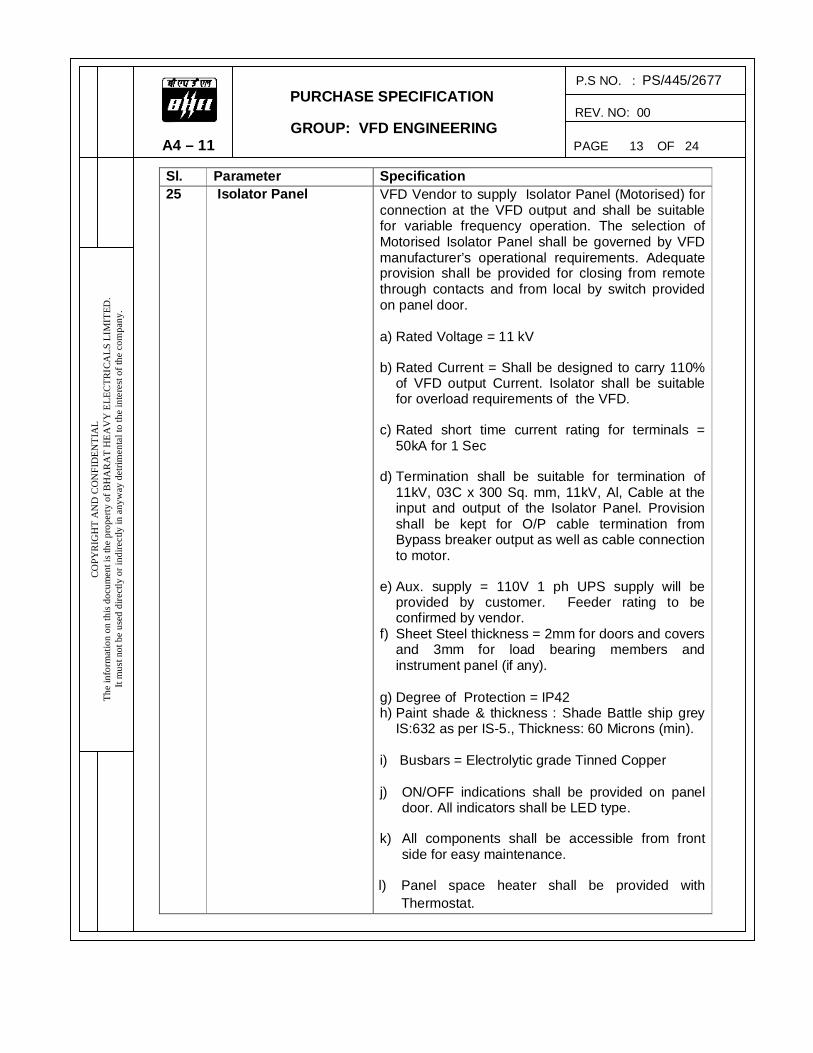
Sl. Parameter Specification 25 Isolator Panel VFD Vendor to supply Isolator Panel (Motorised) for
connection at the VFD output and shall be suitable for variable frequency operation. The selection of Motorised Isolator Panel shall be governed by VFD manufacturer’s operational requirements. Adequate provision shall be provided for closing from remote through contacts and from local by switch provided on panel door. a) Rated Voltage = 11 kV
b) Rated Current = Shall be designed to carry 110% of VFD output Current. Isolator shall be suitable for overload requirements of the VFD.
c) Rated short time current rating for terminals = 50kA for 1 Sec
d) Termination shall be suitable for termination of 11kV, 03C x 300 Sq. mm, 11kV, Al, Cable at the input and output of the Isolator Panel. Provision shall be kept for O/P cable termination from Bypass breaker output as well as cable connection to motor.
e) Aux. supply = 110V 1 ph UPS supply will be provided by customer. Feeder rating to be confirmed by vendor.
f) Sheet Steel thickness = 2mm for doors and covers and 3mm for load bearing members and instrument panel (if any).
g) Degree of Protection = IP42 h) Paint shade & thickness : Shade Battle ship grey
IS:632 as per IS-5., Thickness: 60 Microns (min). i) Busbars = Electrolytic grade Tinned Copper
j) ON/OFF indications shall be provided on panel
door. All indicators shall be LED type.
k) All components shall be accessible from front side for easy maintenance.
l) Panel space heater shall be provided with Thermostat.

P.S NO. : PS/445/2677 PURCHASE SPECIFICATION REV. NO: 00 GROUP: VFD ENGINEERING A4 – 11 PAGE 14 OF 24
CO
PYRI
GH
T A
ND
CO
NFI
DEN
TIA
L Th
e in
form
atio
n on
this
doc
umen
t is t
he p
rope
rty o
f BH
AR
AT
HEA
VY
ELE
CTR
ICA
LS L
IMIT
ED.
It m
ust n
ot b
e us
ed d
irect
ly o
r ind
irect
ly in
any
way
det
rimen
tal t
o th
e in
tere
st o
f the
com
pany
.
Sl. Parameter Specification 25 Isolator Panel m) Facility for padlocking of panel doors shall be
provided. n) Provision shall be provided for charging of spring
charging motor manually. o) Suitable rating Surge Arrestors shall be used for
Isolator. p) Safety interlocks shall be provided in the panel so
that, panel cannot be opened when current is flowing in this circuit.
q) Sub vendor: Isolator shall be sourced from reputed approved sub vendor of VFD manufacturer.
26 Local Control Station (Weather proof) Features
a) The enclosure shall be made of cast light metal Alloy.
b) Degree of protection is IP55.LCS shall be provided with integral canopy.The canopy shall be made of atleast 2mm galvanized sheet steel or FRP.The canopy shall be suitable for providing protection against rain from top and two sides.
c) The LCS shall be provided with gaskets made of non-inflammable and self-extinguishing material.
d) Paint shade is Shade Battle ship grey IS:632 as per IS-5. Paint shade will be confirmed during drawing approval stage.
e) A warning inscription “Isolate power supply elsewhere before opening” shall be provided on the panel. The warning inscription shall be embossed on the enclosure or a separate warning plate fixed to the enclosure with screws. The warning plate shall be nickel plated brass or stainless steel.
f) The LCS shall be provided with two earthing studs with lugs on external surface of enclosures suitable for termination of 8 SWG GI wire.
g) The Emergency Stop push button shall be mushroom type with stay put feature and lockable in pressed position. h) Sub vendor: LCS shall be sourced from
reputed approved sub vendor of VFD manufacturer.

P.S NO. : PS/445/2677 PURCHASE SPECIFICATION REV. NO: 00 GROUP: VFD ENGINEERING A4 – 11 PAGE 15 OF 24
COPY
RIG
HT
AN
D C
ON
FID
ENTI
AL
The
info
rmat
ion
on th
is do
cum
ent i
s the
pro
perty
of B
HA
RA
T H
EAV
Y E
LEC
TRIC
ALS
LIM
ITED
. It
mus
t not
be
used
dire
ctly
or i
ndire
ctly
in a
nyw
ay d
etrim
enta
l to
the
inte
rest
of t
he c
ompa
ny.
Sl. Parameter Specification 26 Local Control Station
(Weather proof) Features
i) All control switches shall be provided with a pistol grip handle.
j) Meters shall be suitable for the appropriate input and shall be calibrated for the actual parameters. Further, for Bypass operation, the meters shall be capable of reading bypass full load and starting currents, as well as the drive current.
1) 4-20mA Signals for Display from VFD: i. Actual Current (0-150A) ii. Actual Speed(0-3000rpm)
2) 0-1A signal for display of Bypass Current with suppressed scale 0-150A/900A
k) Nickel plated brass cable glands (Weather proof) and tinned Copper lugs for cable termination shall be provided by the vendor.
l) 230V Control supply to LCS shall be provided by customer.
27 Type of Control: Completely programmable by the user as: a) Flux vector control with speed feedback b) Flux vector control without speed feedback c) Scalar V/F.
VFD shall be capable of maintaining motor speed within ±0.5% without the use of a motor mounted encoder or tachometer. The drive shall have programmable V/F patterns along with user definable custom V/F patterns.
28 Harmonic Limitations – Source
Shall be as per latest IEEE 519 Voltage harmonics: Vendor to inform the values with calculations during detailed engineering stage. Current harmonics: Vendor to inform the source side 5th, 7th & 11th harmonics values with calculations during detailed engineering stage. Vendor to supply harmonic filters, if required, to filter the harmonics generated by VFD at input/ supply side.
29 Harmonics at VFD Output / Motor Input
Shall be as per latest IEC 61800-4 Vendor to specify the maximum amount of voltage and current harmonics at the VFD Output / Motor Input terminals. It should not be more than 5%. If it is more than 5%, vendor has to provide output filter.

P.S NO. : PS/445/2677 PURCHASE SPECIFICATION REV. NO: 00 GROUP: VFD ENGINEERING A4 – 11 PAGE 16 OF 24
COPY
RIG
HT
AN
D C
ON
FID
ENTI
AL
The
info
rmat
ion
on th
is do
cum
ent i
s the
pro
perty
of B
HA
RA
T H
EAV
Y E
LEC
TRIC
ALS
LIM
ITED
. It
mus
t not
be
used
dire
ctly
or i
ndire
ctly
in a
nyw
ay d
etrim
enta
l to
the
inte
rest
of t
he c
ompa
ny.
Sl. Parameter Specification 30 Switching frequency To be specified by the vendor 31 Auxiliary Supply a) 110V UPS feeder for VFD will be provided by
Customer. KVA Rating is to be given by the Vendor. Power supply for electronic modules has to be derived from the UPS.
b) 110V UPS feeder for Isolator panel will be provided by Customer.
c) Auxiliary Supply – 415V, 3, 50Hz, 4 wire will be provided by customer. Feeder Power rating (short time & continuous) to be specified by the Vendor.
d) Other supplies required by the VFD system to be generated internally within the VFD system.
e) 230V AC non-UPS feeder for LCS shall be provided by Customer. Feeder Power rating to be specified by the Vendor.
32 Testing and Quality Plan
a) Routine Tests shall be carried out on all VFD and transformer panels as per relevant standards.
b) Temperature rise test shall be conducted as Type test on one VFD along with Transformer.
c) For other type tests, Type Test reports conducted earlier on similar type of equipment to be furnished for verification during detailed engineering. If valid type test certificates for transformer and VFD panels are not available as per DCM Specification, vendor shall conduct the type tests without any cost implication to BHEL.
d) During fabrication, the drive and Transformer shall be subject to inspection by BHEL/ Customer, or by an agency authorized by the BHEL/ Customer to assess the progress of work, as well as to ascertain that only quality raw material is used.

P.S NO. : PS/412/ PURCHASE SPECIFICATION REV. NO: 00 GROUP: VFD ENGINEERING A4 – 11 PAGE 13 OF 17
COPY
RIG
HT
AN
D C
ON
FID
ENTI
AL
The
info
rmat
ion
on th
is do
cum
ent i
s the
pro
perty
of B
HA
RA
T H
EAV
Y E
LEC
TRIC
ALS
LIM
ITED
. It
mus
t not
be
used
dire
ctly
or i
ndire
ctly
in a
nyw
ay d
etrim
enta
l to
the
inte
rest
of t
he c
ompa
ny.
P.S NO. : PS/445/2677 PURCHASE SPECIFICATION REV. NO: 00 GROUP: TRACTION ENGINEERING A4 – 11 PAGE 17 OF 24
COPY
RIG
HT
AN
D C
ON
FID
ENTI
AL
The
info
rmat
ion
on th
is do
cum
ent i
s the
pro
perty
of B
HA
RA
T H
EAV
Y E
LEC
TRIC
ALS
LIM
ITED
. It
mus
t not
be
used
dire
ctly
or i
ndire
ctly
in a
nyw
ay d
etrim
enta
l to
the
inte
rest
of t
he c
ompa
ny.
Sl. No.
Parameter Specification
33 Inspection, Training and Commissioning Support
a) Final Inspection: BHEL / Customer representative will be present at manufacturer’s works for witnessing of final testing. This is to be incorporated in the Quality Plan. No charges shall be applicable for witnessing of final tests.
b) Training: Training for 4 (Four) persons from BHEL / Customer for a period of 1 week at manufacturer’s works/site free of cost.
c) Commissioning: Commissioning of all VFD Systems at site shall be in the scope of Vendor. Final Acceptance shall be based on successful completion of the same.
d) Any replacement of failed/damaged items during commissioning shall be exclusively at Vendor’s cost.
e) Vendor is advised to stock necessary spares and ensure easy availability to facilitate trouble free commissioning.
34 Laptop & Software for Computer Interface
Laptop shall be installed with Latest Compatible Licensed Operating System. The software must be loaded in the laptop & supplied along with interconnecting cables and accessories required for interface with the drive. The software should be an easy to use commissioning tool for drives and shall be provided along with the system. The interface details of VFD shall be incorporated as required for data communication with DCS system with serial interfaces with RS485 data links. Necessary hardware shall be included in the scope and the interface protocol shall be provided during detailed engineering.
35 Maintenance The procedure for maintenance of VFD panels and the schedule thereof shall be mentioned in the offer.

v
P.S NO. : PS/445/2677 PURCHASE SPECIFICATION REV. NO: 00 GROUP: VFD ENGINEERING A4 – 11 PAGE 18 OF 24
COPY
RIG
HT
AN
D C
ON
FID
ENTI
AL
The
info
rmat
ion
on th
is do
cum
ent i
s the
pro
perty
of B
HA
RA
T H
EAV
Y E
LEC
TRIC
ALS
LIM
ITED
. It
mus
t not
be
used
dire
ctly
or i
ndire
ctly
in a
nyw
ay d
etrim
enta
l to
the
inte
rest
of t
he c
ompa
ny.
36 Confirmations/Deviations to Specification
Point-wise confirmation to this specification to be given along with offer. Deviations, if any, shall be indicated separately. If there are no deviations to the specifications, supplier shall mention the same explicitly. A reply from vendor stating that “Equipment will generally meet the specifications” will not be accepted by BHEL. Clause-wise Confirmation / Clarifications of all Clauses in the Purchase Specifications 1 to 35 of Specification shall be furnished in the format below.
Point No. Page No. Confirmation / Clarification / Information / Deviation
Details Remarks, if any
7. Consolidated Scope of Supply and Services Sl. No. Items Quantity (Nos.)
1. a) Fully Assembled Units of 11kV VFD Panels (IGBT/SGCT/IGCT), Air Cooled with integrated Dry type transformer
2 Nos.
b) Weather proof Local control station 2 Nos. c) Isolator (Motorised) Panel 2 Nos.
2. Laptop 1 No. 3. Erection Supervision & Commissioning
(Vendor to quote lumpsum commissioning charges for 12 days per drive which shall be considered for bid evaluation) Payment shall be made for actual mandays consumed at Site with per day charges calculated on the basis of the lumpsum charges quoted above. Lumpsum charges quoted shall include travelling, boarding and lodging expenses.
02 lots (lumpsum)
P.S NO. : PS/445/2677 PURCHASE SPECIFICATION REV. NO: 00 GROUP: VFD ENGINEERING A4 – 11 PAGE 19 OF 24
COPY
RIG
HT
AN
D C
ON
FID
ENTI
AL
The
info
rmat
ion
on th
is do
cum
ent i
s the
pro
perty
of B
HA
RA
T H
EAV
Y E
LEC
TRIC
ALS
LIM
ITED
. It
mus
t not
be
used
dire
ctly
or i
ndire
ctly
in a
nyw
ay d
etrim
enta
l to
the
inte
rest
of t
he c
ompa
ny.
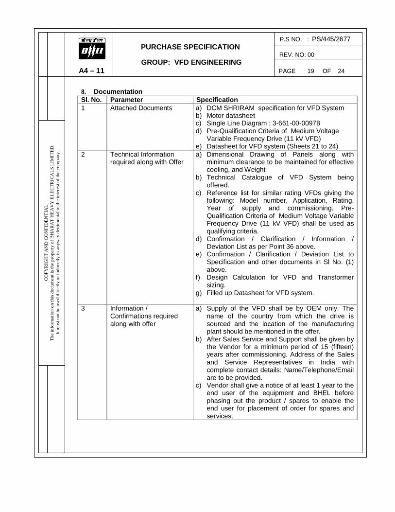
8. Documentation Sl. No. Parameter Specification 1 Attached Documents a) DCM SHRIRAM specification for VFD System
b) Motor datasheet c) Single Line Diagram : 3-661-00-00978 d) Pre-Qualification Criteria of Medium Voltage
Variable Frequency Drive (11 kV VFD) e) Datasheet for VFD system (Sheets 21 to 24)
2 Technical Information required along with Offer
a) Dimensional Drawing of Panels along with minimum clearance to be maintained for effective cooling, and Weight
b) Technical Catalogue of VFD System being offered.
c) Reference list for similar rating VFDs giving the following: Model number, Application, Rating, Year of supply and commissioning. Pre-Qualification Criteria of Medium Voltage Variable Frequency Drive (11 kV VFD) shall be used as qualifying criteria.
d) Confirmation / Clarification / Information / Deviation List as per Point 36 above.
e) Confirmation / Clarification / Deviation List to Specification and other documents in Sl No. (1) above.
f) Design Calculation for VFD and Transformer sizing.
g) Filled up Datasheet for VFD system.
3 Information / Confirmations required along with offer
a) Supply of the VFD shall be by OEM only. The name of the country from which the drive is sourced and the location of the manufacturing plant should be mentioned in the offer.
b) After Sales Service and Support shall be given by the Vendor for a minimum period of 15 (fifteen) years after commissioning. Address of the Sales and Service Representatives in India with complete contact details: Name/Telephone/Email are to be provided.
c) Vendor shall give a notice of at least 1 year to the end user of the equipment and BHEL before phasing out the product / spares to enable the end user for placement of order for spares and services.

P.S NO. : PS/445/2677 PURCHASE SPECIFICATION REV. NO: 00 GROUP: VFD ENGINEERING A4 – 11 PAGE 20 OF 24
COPY
RIG
HT
AN
D C
ON
FID
ENTI
AL
The
info
rmat
ion
on th
is do
cum
ent i
s the
pro
perty
of B
HA
RA
T H
EAV
Y E
LEC
TRIC
ALS
LIM
ITED
. It
mus
t not
be
used
dire
ctly
or i
ndire
ctly
in a
nyw
ay d
etrim
enta
l to
the
inte
rest
of t
he c
ompa
ny.
4 Technical (unpriced) and Commercial (priced) Bids – For Evaluation
Refer sheet no. 18 of 24. Unpriced and Priced bids for Sl. Nos. 7(1), 7(2) & 7(3).
5 Information required for
Customer / Consultant Approval (within 3 weeks from the date of Purchase Order)
a) Dimensional Drawing of Panels along with minimum clearance to be maintained for effective cooling, and Weight
b) Schematic Diagram c) Bill of Materials for equipment to be supplied d) Feeder Requirements – UPS and 415V supply e) Losses at Rated Load (including Fans) f) Heat Loss for Air Conditioning System sizing g) Technical Catalogue of VFD System being
offered h) Test Protocol and Quality Plan i) Type test certificates of similar or higher rating
equipment j) Filled up Data sheet for VFD system
6 Information Required along with Supply. Maintenance Manuals and Documentation
a) Erection, Commissioning and Maintenance Manuals along with Final Drawings and Documentation – 2 Copies
b) Test and Guarantee Certificates. c) Complete Bill of Material (item wise) for the
equipment supplied. d) 1 no. CD ROM consisting of the above.

P.S NO. : PS/445/2677 PURCHASE SPECIFICATION REV. NO: 00 GROUP: VFD ENGINEERING A4 – 11 PAGE 21 OF 24
COPY
RIG
HT
AN
D C
ON
FID
ENTI
AL
The
info
rmat
ion
on th
is do
cum
ent i
s the
pro
perty
of B
HA
RA
T H
EAV
Y E
LEC
TRIC
ALS
LIM
ITED
. It
mus
t not
be
used
dire
ctly
or i
ndire
ctly
in a
nyw
ay d
etrim
enta
l to
the
inte
rest
of t
he c
ompa
ny.
VFD SYSTEM DATA SHEET
A Environment Specifications 1 Maximum Ambient Temperature 50°C 2 Minimum Ambient Temperature 12°C 3 Equipment Design Temperature (IS-9676) 50°C 4 Relative Humidity 95% 5 Altitude Less than 1000m above mean sea level
6 Location of VFD Panels Indoor, Ventilated Room with Air Conditioning.
7 Seismic Zone As per IS-1893-Zone-II B Motor Data 1 Type Squirrel Cage Induction Motor 2 Scope Manufactured by BHEL-Bhopal 3 Rated Power (KW) 2200 KW 4 Rated Voltage and Current 11 KV & 133 A 5 Rated RPM 2990 RPM 6 Duty Class Continuous - S1 C Input Power Supply Data 1 System Voltage / Frequency / Phase 11kV / 50Hz / 3 2 Voltage Variation ±10% 3 Frequency Variation ±5%
4 Combined Voltage and Frequency Variation +10%
5 Fault Level 50kA for 1sec D System Requirements 1 Drive application BFP 2 Speed range required As per application requirement 3 Speed Adjustment Auto (from DCS) and Manual (From Drive) 4 Reference Signal 4-20 mA from DCS 5 Bypass Operation Yes (Manual) 6 Synchronous Bypass No 7 Input Breaker and Bypass Breaker Yes (in BHEL Scope) 8 Fault diagnostic Required Required
9 Cable distance between Input Breaker and VFD 30 meters (approx.)
10 Cable distance between VFD and Motor 200 meters (approx.)

P.S NO. : PS/445/2677 PURCHASE SPECIFICATION REV. NO: 00 GROUP: VFD ENGINEERING A4 – 11 PAGE 22 OF 24
COPY
RIG
HT
AN
D C
ON
FID
ENTI
AL
The
info
rmat
ion
on th
is do
cum
ent i
s the
pro
perty
of B
HA
RA
T H
EAV
Y E
LEC
TRIC
ALS
LIM
ITED
. It
mus
t not
be
used
dire
ctly
or i
ndire
ctly
in a
nyw
ay d
etrim
enta
l to
the
inte
rest
of t
he c
ompa
ny.
11
Separate PE Conductor between VFD & Motor (Vendor to Confirm)
12 Interface with DCS (Modbus) Required E VFD Data 1 Manufacturer 2 Model No. 3 Manufacturing Location 4 Rating 5 Applicable codes /standards 6 Speed reference 4-20 mA from DCS 7 Speed range 8 Switching Frequency 9 No. of Pulse
10 Total number of Diodes/ IGBTs/ IGCTs 11 Drive output Voltage 11kV 12 Overload capability at 115% over current 60 Secs. 13 Inrush current 250% In for
14 Combined efficiency (Transformer & Drive) at:
i) 100% Load ii) 75% Load iii) 50% Load iii) 25% Load
15 Overall power factor at: i) 100% Load ii) 75% Load iii) 50% Load iii) 25% Load
16 Output voltage range and Accuracy 17 Output Frequency range and Accuracy 18 Type of Cooling 19 Redundancy in Cooling 21 Output Filter/ Choke: i) Manufacturer ii) Type/ Model No. iii) Rated Current and Voltage
22 VFD Panel Dimension i) Length (mm) ii) Height (mm) iii) Depth (mm)

P.S NO. : PS/445/2677 PURCHASE SPECIFICATION REV. NO: 00 GROUP: VFD ENGINEERING A4 – 11 PAGE 23 OF 24
COPY
RIG
HT
AN
D C
ON
FID
ENTI
AL
The
info
rmat
ion
on th
is do
cum
ent i
s the
pro
perty
of B
HA
RA
T H
EAV
Y E
LEC
TRIC
ALS
LIM
ITED
. It
mus
t not
be
used
dire
ctly
or i
ndire
ctly
in a
nyw
ay d
etrim
enta
l to
the
inte
rest
of t
he c
ompa
ny.
iv) Weight (kg)
(Dimensional details of all panels shall be furnished)
23 a) Acceleration time b) Deceleration time
24 Degree of protection 25 Paint Shade As per BHEL Specification 26 Heat Load (kW) 27 Auxiliary Power Requirement: 415V, 3Ph, 4 wire UPS supply i) KVA ii) Voltage & Phase
F Transformer Data 1 Manufacturer 2 Manufacturing Location
3 Type Dry type integrated Transformer 4 Duty Continuous (Converter Duty)
5 Rating (Transformer must be designed to carry 110% current of calculated VFD rating.)
6 Class of insulation and temp rise 7 Insulation level: P. f withstand i) HV Winding ii) LV Winding Impulse withstand i) HV Winding ii) LV Winding 8 Fault Level on HV Side 50kA for 1 Sec 9 HV Voltage and Phase 11kV and 3Ph.
10 LV Voltage/ Current 11 No. of LV Windings 12 Rated Frequency 50Hz 13 Impedance 14 Cooling Type 15 Winding Material Electrolytic grade Copper 16 Location of Tap Changer HV Winding 17 No. of Taps and Type 18 Vector Group 19 Neutral CT specification: 51G 64R Vk

P.S NO. : PS/445/2677 PURCHASE SPECIFICATION REV. NO: 00 GROUP: VFD ENGINEERING A4 – 11 PAGE 24 OF 24
COPY
RIG
HT
AN
D C
ON
FID
ENTI
AL
The
info
rmat
ion
on th
is do
cum
ent i
s the
pro
perty
of B
HA
RA
T H
EAV
Y E
LEC
TRIC
ALS
LIM
ITED
. It
mus
t not
be
used
dire
ctly
or i
ndire
ctly
in a
nyw
ay d
etrim
enta
l to
the
inte
rest
of t
he c
ompa
ny.
Im at Vk/2 RCT
20 Cable Size/Type i) HV Winding ii) LV Winding
21 No Load Loss i) At 100% Voltage ii) At 110% Voltage
22 Full Load Copper loss at 75°C 23 No Load Current i) At 100% Voltage ii) At 110% Voltage
24 Efficiency at 75°C and unity power factor i) At 100% of Full Load ii) At 75% of Full Load iii) At 50% of Full Load iv) At 25% of Full Load
25 Efficiency at 75°C and 0.8 power factor i) At 100% of Full Load ii) At 75% of Full Load iii) At 50% of Full Load iv) At 25% of Full Load
26 Load at which maximum efficiency occurs 27 Regulation at 75°C at full load i) At 0.8 pf ii) At UPF
28 Dimensions i) Length (mm) ii) Height (mm) iii) Depth (mm) iv) Weight (kg)
29 Degree of protection for enclosure. 30 Paint Shade 31 Heat Load (kW)

1.00.00
1.01.00
1.02.00
1.03.00
1.04.00
1.05.00
1.06.00
1.07.00
1.08.00
0 GE
0 CO
Tra
Dry
Har
Con
0 Theverynois
0 For relacondfailu
0 All e10%spec
0 Theope
i)
ii)
iii)
0 The
progacceprog
0 EacThemotexci
0 Thebe a
Developme
NERAL
ODES & ST
nsformer
Transforme
rmonics & E
ntactor/ Swi
e system shy high reliabse.
the purpostive humiditditioned ro
ure of air−co
equipment s% combinedcification.
e drive sysrating mode
Variable
Consta
Constanspeed in
e drive contrgrammable eleration/degrammable
ch channel ae system shor Critical sitation syste
e Total Harmas per IEC 6
Techn
HT & LT Varia
nt Consultants
HT & LT VA
Tec
TANDARD
er
EM compatib
tches/ Fuse
hall be enerbility, high p
e of designty of 95% som. Howevondition.
shall be suit variation o
tem shall es as to sui
e torque ch
nt torque ov
nt power ovncreases
roller shall bfunctions.
eceleration from 0.1 to
and motor rall be desig
speed and sem offered.
monic Disto61800-4 an
nical Writeup
For
able Frequency
s Pvt. Ltd.
ARIABLE FR
chnical Req
DS
bility
es etc.
rgy efficientpower facto
n of equipmhall be conver, equipm
table for ratof voltage a
be designet characteri
anging as a
ver a specif
ver a specif
be equippeThe pow
current limio 20 second
rating shall gned for lineshall be of a
rtion (THD)d it shall be
y Drive
Page 1 of
REQUENCY
quirements
IS:2026
IS:11171
IEEE:519/I
IEC:60947
t, designed r, low harm
ent/systemssidered. Th
ment shall b
ted frequennd frequenc
ed to operistics of the
a function o
fic speed ra
fic speed ra
ed with micrer control t curve and
ds.
be rated toear continua modern p
) of the volte considered
13
HT
DRIVE
s
EC:61000/
, IS:13947
as standarmonic distort
s, an ambiehe VFD panbe suitable
cy of 50Hz cy unless sp
rate in onedriven equ
f speed i.e.
ange
ange where
roprocessorregulator
d shall be ca
o meet driveous speed
proven desig
age and cud in the des
1 X 120 MW
Jhagadi
T & LT Variab
IEC 61800
rd product ation and low
ent temperaels shall be
e for opera
with a variapecifically b
e or more ipment
. speed squ
the torque
r based diglogic shallapable of fie
en equipmecontrol fromgn and fully
urrent at invsign of the m
W Coal Based Re
ia, Bharuch, Gu
V
le Frequency D
ANNEX
-4
and shall pw vibration/
ature of 50˚e located in tion even d
ation of ± 5%brought out
of the foll
uared
decreases
ital regulatoprovide f
eld be sepa
ent requiremm 60% to 8y compatibl
verter outpumotor.
eheat TPP
ujarat
ol. II
Drive
XURE-I
rovide wear/
C and an air during
% and in the
lowing
when
or with for an arately
ments. 80% of e with
t shall

1.09.00
1.10.00
1.11.00
1.12.00
1.13.00
1.14.00
1.15.00 1.16.00
1.17.00
2.00.00
0 Theminvariadriveagaminthe
0 Durload60 s
0 Thefor bpoin
0 Thespee
0 Maxnorm
0 The
a)
b)
c)
d)
0 Pain
0 Conserv
0 All tof rStatand
0 TYP
ThesimiInvesimicaserem
Developme
e overload cute for consable torquee shall autinst overloaute, the drivdrive.
ing operatiod condition tseconds.
e integrator both an upwnt adjustme
e drive shaed or reduc
ximum noisemal cooling
e drive syste
Harmfuelimina
VFD indso there
Motor is
No app
nt shade sh
ntractor shavices.
the equipmrelevant Natutory Regu
d equivalent
PE
e Variable filar applicaterter (VSI) ilar in all ree of major oved from t
Techn
HT & LT Varia
nt Consultants
capacity of tstant torque
e applicatiotomatically ad. If the love shall sh
on, the systto respond
action of thward and dnts by the d
ll trip in caces to 95% o
e level fromfans opera
em shall en
l VFD indted.
duced torque is minima
s protected
reciable inc
all be as pe
all provide fu
ent, materiaational andulations. Elet internation
frequency dtions in powtype with m
espect to otfailure in
the defectiv
nical Writeup
For
able Frequency
s Pvt. Ltd.
the controlle applicatio
on at rated reduce the
oad demandut down to
tem shall beto a 20% a
e speed sedownward adistributed c
ase the speof the minim
m the drive aating shall n
sure followi
duced har
ue pulsational stress to t
from dv/dt
crease in m
er owner’s g
ully compat
al and systed Internatioectrical perfnal standard
drive (VFD)wer plants/minimum Ther VFD paany of the
ve VFD pan
y Drive
Page 2 of
er shall be ons, and 11
voltage. If e frequencyd exceeds prevent ov
e capable olteration in
t point alteralteration. Tcontrol syste
eed exceedmum operat
at one (1) mot exceed 8
ing:
monics wh
n are limitedhe equipme
stresses.
otor audible
guideline.
ible electric
ems shall, ional Codesformance ofd.
system sh/industry. TTwelve (12)anels to be
VFD paneel and conn
13
HT
150% of ra5% of ratedthe motor
y and voltathe current
verheating o
of developinspeed set p
ration shall The minimumem shall be
ds 105% otional speed
meter distan85dBA.
hich can c
d to maximent
e noise.
cal system, e
n general, cs & Standaf the system
hall be of ahe system
pulse desprovided a
els, Power nected to th
1 X 120 MW
Jhagadi
T & LT Variab
ated currentd current foload excee
age to thet limit for mof the moto
ng sufficientpoint within
be indepenm time inte
e considered
of the maximd for more t
nce, under r
create mo
mum 1% (ev
equipment,
conform to ards, espem shall com
a modern pshall be of
sign. One sand erected
& Control he spare VF
W Coal Based Re
ia, Bharuch, Gu
V
le Frequency D
t of motor foor one minueds the lim
motor to more than o
r and dama
t torque unda time limit
dently adjuerval betweed as 10 sec
mum operathan 10 sec
rated load w
tor heating
ven at low s
accessorie
the latest ecially the
mply to IEEE
proven desif Voltage Sspare VFD d for each u
Cables shFD panel.
eheat TPP
ujarat
ol. II
Drive
or one ute for
mit, the guard ne (1) age to
der all t up to
stable en set
cond.
ational cond.
with all
g are
speed)
es and
edition Indian E, IEC
gn for Source
panel unit. In hall be

3.00.00
4.00.00
4.01.00
4.02.00
0 OP
Genbe sthe outpgenprotloadfor t
0 DES
Sys
a)
b)
c)
d)
e)
f)
0 VFD
1)
2)
0 BRE
1)
2)
Developme
ERATION
neral requiresuitable for requiremen
put devices erated at thtections liked loss, outpthe system
SIGN AND
stem shall in
Power/csystem
VFD tra
Breake
DC air c
Motor s
LT pow
D TRANSFO
TYPE
Indoor nsystem
RATING
The Traconditio
EAKER/ CO
TYPE
Shall beenergy
These sprotectioElectronswitchin
TEMPE
Techn
HT & LT Varia
nt Consultants
AL REQU
ements of Vlinear cont
nt of drivento meet th
he input of Ve Over loadut short circshall be pro
D CONSTR
nclude the f
control panfor drive co
ansformer o
r/Contactor
core reacto
suitable for V
wer & contro
ORMER, (if
natural air-cdetails.
G
ansformers ons after con
ONTACTOR
e SF6 or vaoperated an
shall be eleon against nic control ng devices.
ERATURE R
nical Writeup
For
able Frequency
s Pvt. Ltd.
IREMENT
VFD systemtinuous spen equipmen
he requiremVFD panelsd, earth faucuit, input trovided.
RUCTION
following eq
nels consistiontrol & pro
on the sourc
r on the mot
or or capacit
VFD applica
ol cables/ca
f applicable
cooled dry t
shall be siznsidering fin
R
acuum typend with elec
ectrically oover loadmodule s
RISE
y Drive
Page 3 of
TS
m shall confed control fnt. The sysents of IEE
s and transflt, Over volransient pro
FEATURE
quipment for
ing of line cotection.
ce side, if re
tor side.
tor as per th
ation
bling as req
)
type and sh
zed so as tnal load req
e or air-breactrical anti-p
perated, m, all AC/D
shall be el
13
HT
form to IECfor a range stem shall
EE 519 & IEferred to potage, Over
otection etc
ES
r each drive
converters,
equired.
he system re
quired inside
all be suita
to have 10%quirements a
ak (for LT spumping fea
echanicallyC transientectrically is
1 X 120 MW
Jhagadi
T & LT Variab
: 61800-2. indicated ehave nece
EC-61000 fower supply
speed, negc. as require
e.
load conve
requirement
e the VFD p
ble for ratin
% margin aat peak con
system) resatures.
y latched tyts and voltsolated fro
W Coal Based Re
ia, Bharuch, Gu
V
le Frequency D
The systemelsewhere aessary inpuor the harmbus. All req
gative sequed and appl
erters and c
t.
panels.
ng complyin
at design amnditions.
strike free, s
ype & shalltage surgeom these
eheat TPP
ujarat
ol. II
Drive
m shall as per ut and monics quired uence, icable
control
g with
mbient
stored
have s etc. power

4.03.00
4.04.00
3)
0 CAP
Shabe awhicis dcurr
0 POW
1)
2)
3)
4)
5)
6)
Developme
Temper40˚C fo
CT/PT/Mvariable
PACITOR (
all be self-han integral ch shall be isconnectedrents.
WER CONT
Housing
Metal eenvironEnclosu
Control
Protectietc. of changeo
Constru
Proper temperacontinuosame sThe noi
Control printer lpanel soffer proProvisiosystem
Copper provisiocomponbus bar
All the cidentifieand coninsulatebe usedcontrol
Techn
HT & LT Varia
nt Consultants
rature rise or other joint
Meters (Ase frequency
as applicab
ealing film part of VFDcapable of d from the s
TROLLER
g
enclosure pment fabricure thicknes
& Protectio
on shall bepower &
over shall b
uction
ventilation ature insideous operathall have 1se level ins
system shocated in thhall be proogrammingon shall beand DDCM
earth bus n for conne
nents/parts sand stud fo
control wiringd at both entrol wiringd, fire retar
d provided tfuse rating
nical Writeup
For
able Frequency
s Pvt. Ltd.
of bus barsts, over an a
s required operation.)
ble)
or electrolyD system. Dreducing thsupply sour
panel havincated from css 1.6mm &
on
e provided acontrol de
be provided
shall be e the cubiion of the 00% redun
side the room
all be provhe control r
ovided with and param
e kept for MIS/DDC/Fie
of min. 50ction to Owshall be con
or electronic
g shall be ends by self- inside the
rdant, coppethe control f
above 16A
y Drive
Page 4 of
shall not eambient tem
for the sy)
ytic type haDC link Cahe residual rce. The ca
ng IP-42 decold rolled s
& Gland plat
against overevice. Dup.
provided cle is withsystem. Indancy with m shall be w
vided with 2room for syits own gra
meter monitexchange
eld bus.
0x6 mm sizner/Purchasnnected to control syst
enclosed in p-sticking wire panel shaer conductofuse rating iA for electri
13
HT
exceed 55˚Cmperature o
stem offere
ving high lipacitors shcharges to
apacitor sha
egree of prsheet steel e thickness
rload, AC/Dplicate cont
in the pain permiss
n case cooprovision fo
within the s
21”TFT withstem alarmaphical locaoring facilitiof informa
ze shall be ser’s plant ethe main eatem as requ
plastic/metare marker taall be doner wire. 1.5ms 10 Amps cal circuits
1 X 120 MW
Jhagadi
T & LT Variab
C for silver of 50 ˚C und
ed & shall
ife time. Thall have diszero just a
all be suitab
rotection, loof Frame t
s 4.0mm(Al)
DC transienttrol supply
nels to ensible limits ling fans afor auto stapecified lim
h keyboard m and monit
al control pies with disation betwe
provided iearth grid. Aarth bus bauired shall b
al channel. Eapes of PVCe with BIS
mm2 size wor less andand 0.7 m
W Coal Based Re
ia, Bharuch, Gu
V
le Frequency D
plated jointder any con
be suitab
he capacitorscharge res
after the capble for high
ocated in ithickness 2).
ts, voltage sy with auto
nsure that for reliable
are providedrt of standb
mits.
and colouroring. Each
panel whichsplay and aeen VFD c
n the paneAll the non-mar. Separatee provided.
Each wire shC ferrules.
S approved,wire shall nod 2.5mm2 sm2 for elec
eheat TPP
ujarat
ol. II
Drive
ts and dition.
ble for
r shall sistors pacitor ripple
indoor .0mm,
surge, omatic
max. e and d, the
by fan.
r laser h drive h shall larms.
control
el with metallic e earth
hall be Power , PVC ormally ize for ctronic

4.05.00
4.06.00
5.00.00
5.01.01
5.01.02
5.02.00
5.02.01
0 MOT
Thresuitaoneand
0 CAB
Powalumscresymmetovecab
0 TYP
Thelisteopethoseitheclienwithfounsuchapp
2 All abe cprice
0 LIST
Rou
a.
Developme
circuits. minimum
TORS
ee phase sable for VF side. Moto relevant IS
BLES
wer cables minium/coppeened, PV
mmetrical wiallic screenrlap of 20%les and rele
PE TESTIN
e contractor ed in this sning. These
se proposeder conductent. In case
hin the last tnd to be mh tests undroval.
acceptancecarried out.e.
T OF TEST
utine tests
Visual I
It involvwiring, visual in
i)
ii)
iii)
Techn
HT & LT Varia
nt Consultants
All wires sm 20% spar
squirrel cagD applicatiors shall also
S/IEC.
used to iper condu
VC inner sith three syn of each
%.Cables shevant IS/IEC
NG
shall submpecificatione reports shd to be suped at an inthe Contracten years froeeting the er this cont
and routin. Charges f
TS
nspection
ves checkinterminals, enspection s
Dimensions
Degree of p
Simulation
nical Writeup
For
able Frequency
s Pvt. Ltd.
shall be ferre terminal s
ge Inductionon. These mo meet the
nterconnecctors. Thesheathed, ymmetricallycore shall
hall also meC.
mit for Empln and carriehould be fopplied undendependentctor is not aom the datespecificatiotract free o
ne tests as for these s
ng of the vaearthing ra
shall not be
s and door
protection o
facility of co
y Drive
Page 5 of
rruled and shall be prov
n motor witmotors shalrequiremen
ct the VFDese cables
armoured, y positioned
consist of eet the req
oyer’s appred out withor the tests er this cont laboratory able to subme bid openinon requiremof cost to th
per the spehall be dee
arious equiptings etc, inlimited to th
layout vis-a
of cubicles
ontrol signa
13
HT
terminals svided.
h VPI insull be provide
nts mention
to motor shall be PVC out
d insulated copper w
uirements m
roval the repin last ten conducted ract and thor should
mit report ong, or in cas
ments, the Ce Employe
ecification aemed to be
pment/compn line with he following
a-vis the app
als for testin
1 X 120 MW
Jhagadi
T & LT Variab
shall be pro
lation & inved with insued in sub-s
shall haveXLPE ins
ter sheathgrounding
ires or tapmentioned
ports of all years fromon the equ
he test(s) shhave been
of the type tse the typeContractor r and subm
and relevane included i
ponents fauthe approv
g:
proved draw
ng purposes
W Coal Based Re
ia, Bharuch, Gu
V
le Frequency D
operly numb
verter gradeulated bearisection for M
e multi-strasulated, mhed, round
conductorspe with minin subsecti
the type tem the data uipment simhould haven witnessedtest(s) cond test report shall condu
mit the repo
nt standardsin the equip
lt diagnostied drawing
wings
s
eheat TPP
ujarat
ol. II
Drive
bered,
e duty ing on
Motors
anded, metallic d and s. The nimum on for
sts as of bid
milar to e been d by a ducted in not
uct all orts for
s shall pment
c unit, gs and

5.02.02
b.
c.
d.
e.
f.
g.
h.
i.
j.
k.
l.
2 Typ
a.
b.
c.
Developme
iv)
v)
vi)
vii)
viii)
ix)
Insulati
Light lo
Load ch
Load du
Checkin
Checkin
Checkin
Checkin
High vo
Shaft cu
Automa
pe Tests Allowa Efficien Temper
Techn
HT & LT Varia
nt Consultants
Memory fun
Voltage/Cu
Cable term
Accessibilit
External sig
Earthing of
on Test
ad and func
haracteristic
uty test
ng of Auxilia
ng the prop
ng the prote
ng of contro
oltage test
urrent/beari
atic restart/r
ble full load
ncy
rature rise
nical Writeup
For
able Frequency
s Pvt. Ltd.
nction of fa
urrent rating
mination size
ty of compo
gnals and in
f cubicles an
ctional test
cs test
ary devices
perties of the
ective devic
ol and funct
ing insulatio
re-accelerat
d current ve
y Drive
Page 6 of
ult diagnost
g power sem
e and numb
onents
ndication/al
nd cubicle d
s
e control eq
ces
ional requir
on
tion
ersus speed
13
HT
tic
miconductor
er of termin
arm signals
doors.
quipment
rements
1 X 120 MW
Jhagadi
T & LT Variab
r elements
nals, cable-s
s on conver
W Coal Based Re
ia, Bharuch, Gu
V
le Frequency D
supporting e
rter
eheat TPP
ujarat
ol. II
Drive
etc.

d.
e.
f.
g.
h.
i.
j.
k.
l.
m.
n.
o.
p.
Type
for d
Developme
EM Imm EM Em Current Voltage Line sid Power f Audible Torque Motor v Dynam Current Speed Test capafter a
e test certifi
d, e, f, j, k an
Techn
HT & LT Varia
nt Consultants
munity
mission
t sharing
e division
de current d
factor
e noise
pulsation
vibration
ic performa
t limit and c
loop test ca
pability to revoltage inter
cate from in
nd l at the op
nical Writeup
For
able Frequency
s Pvt. Ltd.
distortion co
ance
current loop
apability to r
estart the sysrruption
ndependent
ption of the o
y Drive
Page 7 of
ontent
test
ride through
stem and res
testing agen
owner / purc
13
HT
h voltage les
synchronize
ncy for simila
chaser.
1 X 120 MW
Jhagadi
T & LT Variab
ss than 80%
converter o
ar equipmen
W Coal Based Re
ia, Bharuch, Gu
V
le Frequency D
%
nto running
nt can be acc
eheat TPP
ujarat
ol. II
Drive
motor
cepted

Sl. No.
1.
2.
3.
4.
Equipm
Boiler F
ID Fan
PA Fan
SA Fan
Developme
ment
Feed Pump
n
n
Techn
HT & LT Varia
nt Consultants
LIST OF
nical Writeup
For
able Frequency
s Pvt. Ltd.
VFD OPERA
Tota(WoStan
3 (2
2 (2
2 (2
2 (2
y Drive
Page 8 of
ATED HT MO
al Nuorking ndby)
+ 1)
+ 0)
+ 0)
+ 0)
13
HT
OTORS
umber +
Mo
20
16
16
10
1 X 120 MW
Jhagadi
T & LT Variab
otor Rating
000
600
650
000
W Coal Based Re
ia, Bharuch, Gu
V
le Frequency D
g (KW)
eheat TPP
ujarat
ol. II
Drive
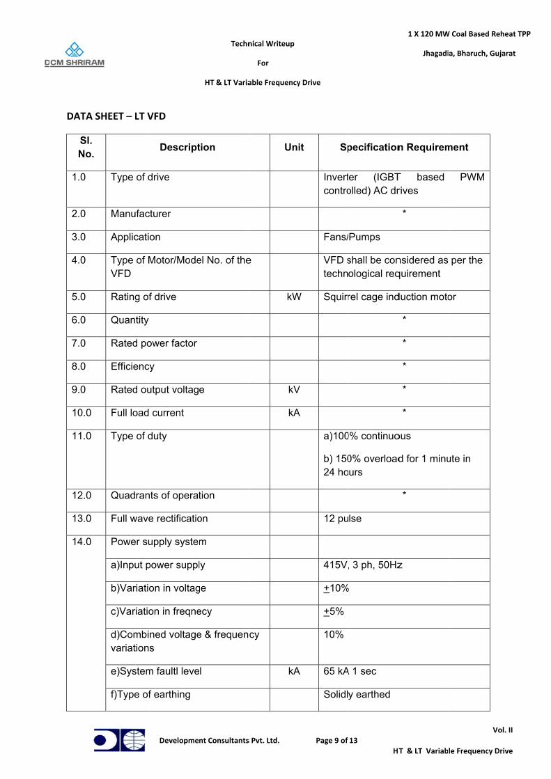
DATA S
Sl. No.
1.0
2.0
3.0
4.0
5.0
6.0
7.0
8.0
9.0
10.0
11.0
12.0
13.0
14.0
SHEET – LT V
Type of d
Manufac
Applicati
Type of MVFD
Rating of
Quantity
Rated po
Efficienc
Rated ou
Full load
Type of d
Quadran
Full wave
Power su
a)Input p
b)Variatio
c)Variatio
d)Combivariation
e)System
f)Type of
Developme
VFD
Descript
drive
cturer
on
Motor/Mode
f drive
ower factor
y
utput voltag
current
duty
nts of operat
e rectificatio
upply syste
power suppl
on in voltag
on in freqne
ned voltages
m faultl leve
f earthing
Techn
HT & LT Varia
nt Consultants
tion
el No. of the
e
tion
on
m
ly
ge
ecy
e & frequen
l
nical Writeup
For
able Frequency
s Pvt. Ltd.
Uni
e
kW
kV
kA
cy
kA
y Drive
Page 9 of
it Sp
Invertcontro
Fans/
VFD stechn
W Squirr
V
A
a)100
b) 15024 ho
12 pu
415V,
+10%
+5%
10%
A 65 kA
Solidl
13
HT
pecification
er (IGBTolled) AC dr
Pumps
shall be conological req
rel cage ind
0% continuo
0% overloadurs
lse
, 3 ph, 50Hz
%
A 1 sec
y earthed
1 X 120 MW
Jhagadi
T & LT Variab
n Requirem
T based rives
*
nsidered asquirement
duction moto
*
*
*
*
*
ous
d for 1 minu
*
z
W Coal Based Re
ia, Bharuch, Gu
V
le Frequency D
ment
PWM
per the
or
ute in
eheat TPP
ujarat
ol. II
Drive
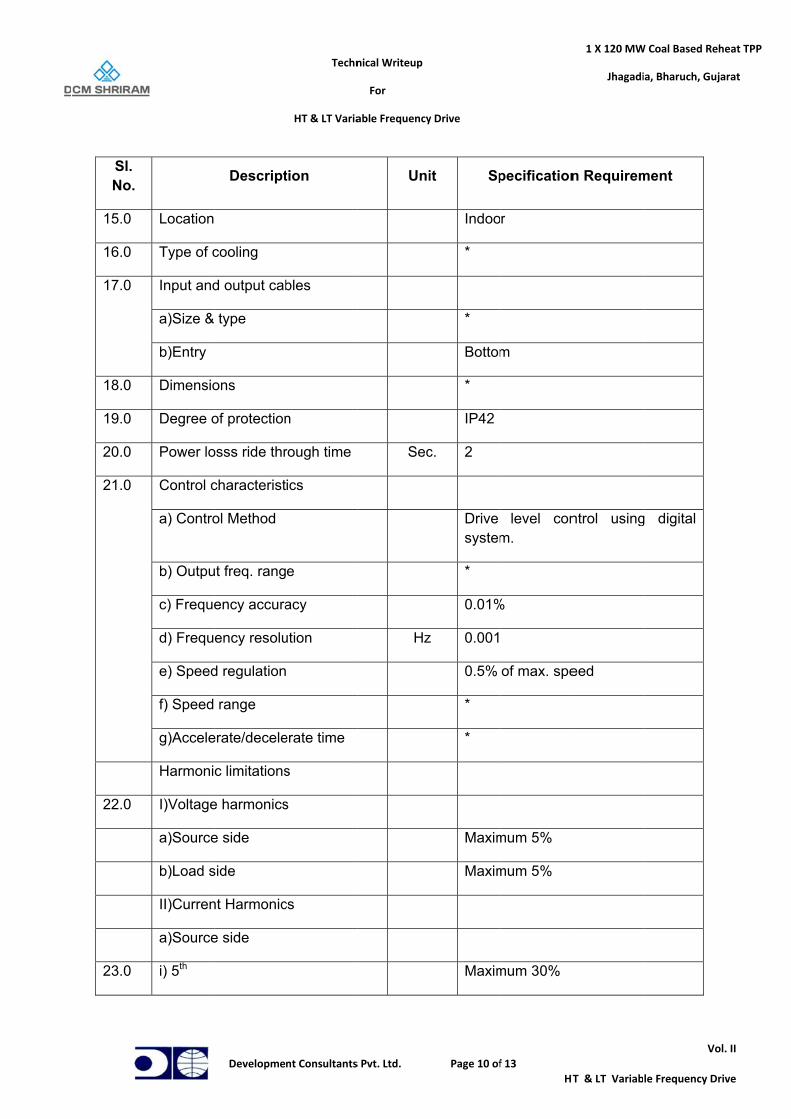
Sl. No.
15.0
16.0
17.0
18.0
19.0
20.0
21.0
22.0
23.0
Location
Type of c
Input and
a)Size &
b)Entry
Dimensio
Degree o
Power lo
Control c
a) Contro
b) Outpu
c) Freque
d) Frequ
e) Speed
f) Speed
g)Accele
Harmoni
I)Voltage
a)Source
b)Load s
II)Curren
a)Source
i) 5th
Developme
Descript
cooling
d output cab
type
ons
of protection
osss ride thr
characterist
ol Method
ut freq. rang
ency accura
ency resolu
d regulation
range
erate/decele
c limitations
e harmonics
e side
side
nt Harmonic
e side
Techn
HT & LT Varia
nt Consultants
tion
bles
n
rough time
ics
e
acy
ution
erate time
s
s
cs
nical Writeup
For
able Frequency
s Pvt. Ltd.
Uni
Sec
Hz
y Drive
Page 10 of
it Sp
Indoo
*
*
Bottom
*
IP42
c. 2
Drive system
*
0.01%
z 0.001
0.5%
*
*
Maxim
Maxim
Maxim
f 13
HT
pecification
r
m
level conm.
%
of max. spe
mum 5%
mum 5%
mum 30%
1 X 120 MW
Jhagadi
T & LT Variab
n Requirem
ntrol using
eed
W Coal Based Re
ia, Bharuch, Gu
V
le Frequency D
ment
g digital
eheat TPP
ujarat
ol. II
Drive
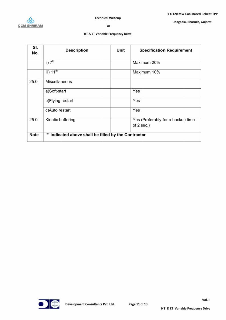
Sl. No.
25.0
25.0
Note
ii) 7th
iii) 11th
Miscellan
a)Soft-st
b)Flying
c)Auto re
Kinetic b
‘*’ indica
Developme
Descript
neous
art
restart
estart
buffering
ated above
Techn
HT & LT Varia
nt Consultants
tion
e shall be fi
nical Writeup
For
able Frequency
s Pvt. Ltd.
Uni
illed by the
y Drive
Page 11 of
it Sp
Maxim
Maxim
Yes
Yes
Yes
Yes (Pof 2 s
e Contracto
f 13
HT
pecification
mum 20%
mum 10%
Preferably fec.)
or
1 X 120 MW
Jhagadi
T & LT Variab
n Requirem
for a backup
W Coal Based Re
ia, Bharuch, Gu
V
le Frequency D
ment
p time
eheat TPP
ujarat
ol. II
Drive
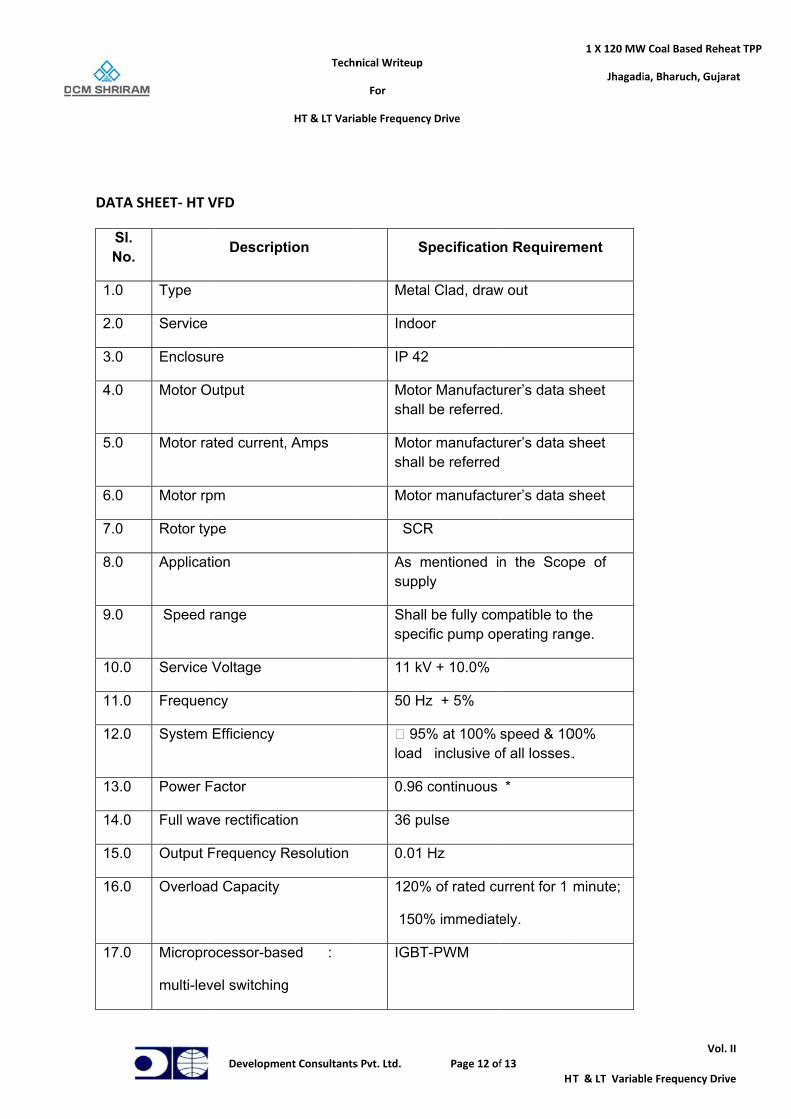
DATA S
Sl. No.
1.0
2.0
3.0
4.0
5.0
6.0
7.0
8.0
9.0
10.0
11.0
12.0
13.0
14.0
15.0
16.0
17.0
SHEET‐ HT V
Type
Service
Enclosur
Motor Ou
Motor rat
Motor rpm
Rotor typ
Applicati
Speed r
Service V
Frequenc
System E
Power Fa
Full wave
Output F
Overload
Micropro
multi-leve
Developme
VFD
Descript
re
utput
ted current,
m
pe
on
range
Voltage
cy
Efficiency
actor
e rectificatio
Frequency R
d Capacity
ocessor-bas
el switching
Techn
HT & LT Varia
nt Consultants
tion
Amps
on
Resolution
sed :
g
nical Writeup
For
able Frequency
s Pvt. Ltd.
Sp
Metal
Indoo
IP 42
Motorshall
Motorshall
Motor
SCR
As msuppl
Shall specif
11 kV
50 Hz
95%load
0.96 c
36 pu
0.01 H
120%
150%
IGBT
y Drive
Page 12 of
pecificatio
l Clad, draw
or
r Manufactube referred
r manufactube referred
r manufactu
R
mentioned iny
be fully comfic pump op
V + 10.0%
z + 5%
% at 100% inclusive o
continuous
ulse
Hz
% of rated cu
% immediate
-PWM
f 13
HT
n Requirem
w out
urer’s data s.
urer’s data s
urer’s data s
n the Scop
mpatible to perating ran
speed & 10of all losses.
*
urrent for 1
ely.
1 X 120 MW
Jhagadi
T & LT Variab
ment
sheet
sheet
sheet
pe of
the nge.
00% .
minute;
W Coal Based Re
ia, Bharuch, Gu
V
le Frequency D
eheat TPP
ujarat
ol. II
Drive
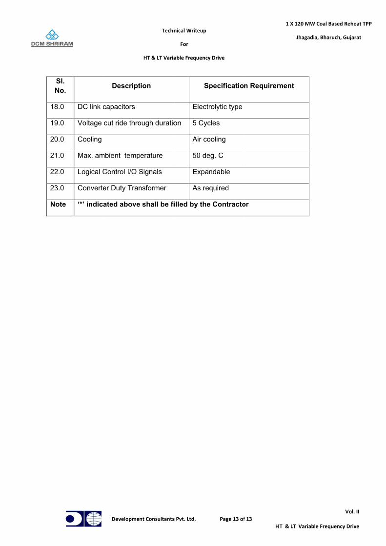
Sl. No.
18.0
19.0
20.0
21.0
22.0
23.0
Note
DC link c
Voltage c
Cooling
Max. am
Logical C
Converte
‘*’ indica
Developme
Descript
capacitors
cut ride thro
bient temp
Control I/O S
er Duty Tran
ated above
Techn
HT & LT Varia
nt Consultants
tion
ough duratio
perature
Signals
nsformer
e shall be fi
nical Writeup
For
able Frequency
s Pvt. Ltd.
Sp
Electr
on 5 Cyc
Air co
50 de
Expan
As re
illed by the
y Drive
Page 13 of
pecificatio
rolytic type
cles
ooling
eg. C
ndable
quired
e Contracto
f 13
HT
n Requirem
or
1 X 120 MW
Jhagadi
T & LT Variab
ment
W Coal Based Re
ia, Bharuch, Gu
V
le Frequency D
eheat TPP
ujarat
ol. II
Drive

BHARAT HEAVY ELECTRICALS LIMITED, BHOPAL DATA SHEET FOR BFP MOTOR
Note1: Data given below is subject to tolerance as per IS/IEC 60034-1 unless specified otherwise.
A. AC MOTOR 1.0 GENERAL 1.1 Application : BFP 1.2 Quantity : 03 1.3 Make : BHEL, Bhopal 1.4 Frame Size : 2RQ 7632-2 1.5 Applicable Standard : IS/IEC 60034-1 2.0 TYPE AND RATING 2.1 Type of Motor : SCIM 2.2 Service : 1.0 2.3 Duty Cycle/Designation : Continuous, S1 2.4 Rated Continuous Output At 40 Deg.C ambient KW : 2350 At 50 Deg.C ambient KW : 2200 2.5 Rated Speed r.p.m. : 2990 2.6 Rated Voltage & % variation : 11kV ± 10% 2.7 Rated Frequency & % variation : 50 ± 5 % 2.7a Combined frequency and voltage : 10% 2.8 Full load current Amps : 133 2.9 No load current Amps : 34 2.10 Rated Power Factor : 0.91 2.11 Efficiency at rated voltage and frequency: a) Full load % : 95.8 b) 3/4 load % : 95.5 c) 1/2 load % : 94.5
Project Name DCM SHRIRAM 1X120MW STG
Client DCM SHRIRAM CONSOLIDATED LTD
BHEL WO :
40050A421-11
Rev.00 Date: 12-Oct-2020

3.0 PERFORMANCE 3.1 Method of Starting : DOL & VFD 3.2 Starting Current at rated voltage % flc. : 600% on DOL start 3.3 Starting Current at 110% voltage (% of full load current) : 660% on DOL start 3.4 Torque at rated voltage kg.m : a) Breakaway starting torque kg m : 358 (50% FLT)
b) Pull out torque kg. m : 1646 (230% FLT) c) Pull up torque kg m : 358 (50% FLT) d) Full load torque kg. m : 716 3.5 Starting time at : 80% 100% 110% Voltage Voltage Voltage a) Motor with coupling i) With load sec. : 13.0 7.0 6.0 ii) Without load (driven equipment coupled) sec : 7.0 4.5 3.5 3.6 Safe stall time at 80% 100% 110% Voltage Voltage voltage a) Hot condition sec. : 37 24 19 b) Cold condition sec. : 46 30 24 3.7 Frequency of start per hour
a) Hot condition : 2
b) Cold condition : 3
c) Equal spread start : 3 3.8 Heating Time Constant (min) : 30 3.9 Cooling Time constant (min) : 120 3.10 Negative sequence time constant (K=Ie
2t) : Refer Curve No. AM40051-11/05 3.11 Noise level : 90 dB at 1m. 3.12 (i) Bearing Vibration level : 2.3 mm/s(rms) 37 µ (rms) (ii) Shaft vibration : 65 µ (P-P)

4.0 CONSTRUCTION 4.1 Degree of Protection of Enclosure : IP55 4.2 Method of Cooling : CACA, IC611 4.3 Insulation :
a) Type : VPI, Resin Poor
b) Class : Class F (Temp. rise limited to Class B) 4.4 Temperature Rise Over 50 Deg.C ambient (by resistance) : 70 4.5 Tropicalized Yes/No : YES 4.6 Winding Connection : STAR 4.7 Bearings D.E. N.D.E. a) Make : DIN Bearing, BHEL Approved/ From GeM b) Type : Sleeve c) Recommended lubricant : ISO VG32 or equivalent
d. Duration of lubrication change : FOL system vendor to recommend. e. Life of bearing : Infinite (if properly maintained) f. For force oil lubrication system : Not in BHEL, Bhopal scope i) Oil flow per bearing (LPM) : 3.5 for each bearing ii) Max/ Min oil pressure (kg-m2) : 0.2-0.5 kg/cm2 4.8 Motor Terminal Box a) Type : PSTB b) Fault withstand Current KA : 50 (through fault) c) Fault Current Withstand Time Sec. : 0.25 d) Cable lugs & glands furnished Yes/No : Gland Furnished, Lug is not in BHEL,Bhopal scope.
e) Position : RHS from DE
f) Rotation 360 deg with
step of 90 deg. (yes/No) : Suitable for 360 º rotation in step of 180º g) Type of thread : BSC

4.9 Mounting a. Shaft extension : Refer OGA drawing b. Direction of rotation from DE side : CCW from DE 4.10 Motor Neutral Terminal Box a) Type : Non-PSTB b) Differential CT provided (Yes/No) : 3 Nos. 4.11 Rotor terminal box : NA 5.0 ACCESSORIES 5.1 Space Heaters a) No. x Watt : 2 X 600W b) Volt, phase, frequency : 240V, 1Ph, 50Hz 5.2 Winding temperature detector a) Type : PT100 Simplex, 3 lead b) Nos. furnished : 12 5.3 Bearing temperature detector a) Type : PT100 Duplex, 3+3 lead b) Nos. furnished : 2 5.4 Hot and cold air temperature detector a. Type : PT100 Duplex, 3+3 lead b. Nos furnished : 1 +1 5.5 Temperature Indicators a) Type : Gas filled Dial Type b) Nos. provided : 2 Nos. for Bearings. c) Locations : On bearing housing
5.6 Temperature Alarm Contact a) Nos. provided : 2 ‘NO’ b) Locations : In-built inside DTT c) Contact rating : 30W, 50VA

5.7 Flow Switch a. Type : NA b. Nos. provided :-- c. Locations : -- d. Contact Rating :-- 5.8 Current Transformer for differential protection a. Nos. provided : 3 Nos. b. Current Ratio : Customer to decide details. c. Class : PS 5.9 Speed Switch a. Type : NA b. Location of switch & terminal box. -- c. Auxiliary supply requirement : - d. Catalogue furnished : -- 5.10 Starting Resistance (slip ring motor) : NA a. Type : -- b. Rating : -- 5.11 Accessory Terminal Box a) No. provided : 1 b) Cable glands furnished : Yes/No: YES 5.12 Insulation of bearing : YES, at NDE 5.13 Lubrication oil level indicator : Sight glass on bearing housing. 5.14 Water flow indicator : NA 5.15 Water leakage detector : NA 5.16 Vibration Pad (Nos. size and location): 2 Nos., 80 X 80 X 80 mm3
5.17 Motor vibration sensor : Not in BHEL Bhopal Scope. 5.18 Any other fitment : NA

6.0 GROUNDING 6.1 No. of grounding pads provided a) On motor body : 2 b) On terminal box : 2 7.0 MISCELLANEOUS 7.1 Type of mounting : Horizontal, B3 7.2 Foundation bolts provided (Yes/No) : In Pump vendor scope. 7.3 Overall dimension (LxBxH) mm x mm x mm : ≈ 4200 X 3200 2800 7.4 Moment of Inertia (Sq.GD) a) Stator Kg.Sq.m : NA b) Rotor Kg.Sq.m : 296 c) Total Kg.Sq.m : 296 7.5 Weight a) Stator+Cooler Kg : 9500 + 1800 b) Rotor Kg : 2700 c) Total Kg : 14000 Motor Equivalent Circuit Parameters: Stator: R1 = 0.165 X1 = 6.48 Ohm Xm =195.72 Ohm Rotor: R2’=(referred to stator)=0.782 Ohm at starting = 0.242 Ohm during running X2’ (referred to stator) = 2.95 Ohm at starting = 4.19 Ohm during running

