revolution high-power q-switched laser system ...€¦ · revolution laser preinstallation manual...
TRANSCRIPT

Preinstallation ManualRevolutionHigh-Power Q-SwitchedLaser System


Preinstallation Manual Revolution High-Power Q-Switched Laser System
5100 Patrick Henry Drive Santa Clara, CA.95054 USA
Revolution Laser Preinstallation Manual
This document is copyrighted with all rights reserved. Under copyright laws, this document may not be copied in whole or in part, or reproduced in any other media, without the express written permission of Coherent, Inc. (Coherent). Permitted copies must carry the same proprietary and copyright notices as were affixed to the original. This exception does not allow copies—whether or not sold—to be made for others; however, all the material purchased may be sold, given, or loaned to another person. Under the law, “copying” includes translation into another language.
Coherent and the Coherent Logo are registered trademarks of Coherent, Inc.
Patents referenced in this manual are active when the manual is printed (see last page for date). You are advised to check to see if the patents are still active http://portal.uspto.gov/external/portal/pair.
Every effort has been made to ensure that the data given in this document is accurate. The information, figures, tables, specifications, part numbers, and schematics contained herein are subject to change without notice. Coherent makes no warranty or representation, either expressed or implied, with respect to this document. In no event will Coherent be liable for any direct, indirect, special, incidental, or consequential damages resulting from any defects in its documentation.
Technical Support
In the U.S.:
Should you experience any difficulties with your laser or need any technical information, please visit our Web site www.Coherent.com. Should you need further assistance, please contact Coherent Technical Support via e-mail [email protected] or telephone, 1-800-367-7890 (1-408-764-4050 outside the U.S.). Please be ready to provide model and laser head serial number of your laser system as well as the description of the problem and any corrective steps attempted to the support engineer responding to your request.
Telephone coverage is available Monday through Friday (except U.S. holidays and company shutdowns). Inquiries received outside normal office hours will be documented by our automatic answering system and will be promptly returned the next business day.
Outside the U.S.:
If you are located outside the U.S., please visit www.Coherent.com for technical assistance, or phone our local Service Representative. Service Representative phone numbers and addresses can be found on the Coherent web site.
Coherent provides telephone and web-based technical assistance as a service to its customers and assumes no liability thereby for any injury or damage that may occur contemporaneous with such services. Under no circumstances do these support services affect the terms of any warranty agreement between Coherent and the buyer. Operation of any Coherent laser with any of its interlocks defeated is always at the operator's own risk.
ii

Table of Contents
TABLE OF CONTENTS
Preface ....................................................................................................................................vExport Control Laws Compliance ........................................................................................ viSignal Words and Symbols in this Manual .......................................................................... vii
Signal Words............................................................................................................... viiSymbols ..................................................................................................................... viii
Section One: Laser Safety .......................................................................................... 1-1Hazards ............................................................................................................................... 1-1
Optical Safety ............................................................................................................ 1-2Recommended Precautions and Guidelines...................................................... 1-2
Protective Eye Wear............................................................................................................ 1-4CE Compliance ................................................................................................................... 1-4CDRH Compliance ............................................................................................................. 1-5
Waste Electrical and Electronic Equipment (WEEE, 2002) ...................................... 1-5Keyswitch .................................................................................................................. 1-5Warning Labels .......................................................................................................... 1-5Remote Interlock Connector .................................................................................... 1-12Protective Housings ................................................................................................. 1-12Cover Safety Interlocks ........................................................................................... 1-12Emission Indicators.................................................................................................. 1-13Beam Safety Shutter ................................................................................................ 1-13Location of Controls ................................................................................................ 1-13Operating Instructions.............................................................................................. 1-13
CDRH Requirements for Operating via RS-232 Software Commands............................ 1-13Maintenance Required to Keep Laser in CDRH Compliance .......................................... 1-14Sources of Additional Information ................................................................................... 1-15
Laser Safety Standards............................................................................................. 1-15Equipment and Training........................................................................................... 1-15
Section Two: Description and Specifications.................................................. 2-1Introduction......................................................................................................................... 2-1Laser Head Assembly ......................................................................................................... 2-2Power Supply Assembly..................................................................................................... 2-2Control Computer ............................................................................................................... 2-2Closed-Loop Chiller ........................................................................................................... 2-3Block Diagram.................................................................................................................... 2-3Remote Interlock Connector ............................................................................................... 2-3Specifications & Environmental Requirements.................................................................. 2-5Dimensions ......................................................................................................................... 2-5
Section Three: Installation and Utility Requirements .............................. 3-1Location and Environment......................................................................................... 3-1Required Utilities ....................................................................................................... 3-1
iii
Revolution Laser Preinstallation Manual
Parts List .............................................................................................................................. A-1
Glossary ..................................................................................................................... Glossary-1
Index ................................................................................................................................. Index-1
LIST OF FIGURES
1-1. Laser Head CDRH/CE Radiation Label Locations ......................................................... 1-51-2. Power Supply CDRH/CE Radiation Label Locations ..................................................... 1-91-3. External Interlock Connector (Revolution Power Supply)............................................ 1-12
2-1. Revolution Laser Head .................................................................................................... 2-12-2. Connection Block Diagram ............................................................................................. 2-42-3. External Interlock Circuit Diagram ................................................................................. 2-42-4. Revolution Laser Head Dimensions ................................................................................ 2-62-5. Revolution Power Supply Dimensions ............................................................................ 2-9
iv

Table of Contents
LIST OF TABLES
1-1. Laser Head CDRH/CE Radiation Labels......................................................................... 1-71-2. Power Supply CDRH/CE Radiation Labels .................................................................. 1-10
2-1. Environmental Requirements .......................................................................................... 2-52-2. Dimensions & Weight...................................................................................................... 2-5
3-1. Revolution Utility Requirements ..................................................................................... 3-1
A-1. List of Orderable Parts ................................................................................................... A-1
v

Revolution Laser Preinstallation Manual
Preface This document contains user information for the Revolution a High Power, Diode-Pumped, Multi-kHz, Q-Switched, Intra-Cavity Doubled, Nd:YLF Laser.
Read this Operator Manual carefully before operating the laser for the first time. Special attention must be given to the material in Section One: Laser Safety.
Use of controls or adjustments or performance of procedures other than those specified in this operator’s manual may result in hazardous radiation exposure.
Use of the system in a manner other than that described herein may impair the protection provided by the system.
Export Control Laws Compliance
It is the policy of Coherent to comply strictly with U.S. export control laws.
Export and re-export of lasers manufactured by Coherent are subject to U.S. Export Administration Regulations, which are administered by the Commerce Department. In addition, shipments of certain components are regulated by the State Department under the Inter-national Traffic in Arms Regulations.
The applicable restrictions vary depending on the specific product involved and its destination. In some cases, U.S. law requires that U.S. Government approval be obtained prior to resale, export or re-export of certain articles. When there is uncertainty about the obligations imposed by U.S. law, clarification must be obtained from Coherent or an appropriate U.S. Government agency.
Products manufactured in the European Union, Singapore, Malaysia, Thailand: These commodities, technology, or software are subject to local export regulations and local laws. Diversion contrary to local law is prohibited. The use, sale, re-export, or re-transfer directly or indirectly in any prohibited activities are strictly prohib-ited.
vi

Preface
Signal Words and Symbols in this Manual
This documentation may contain sections in which particular hazards are defined or special attention is drawn to particular condi-tions. These sections are indicated with signal words in accordance with ANSI Z-535.6 and safety symbols (pictorial hazard alerts) in accordance with ANSI Z-535.3 and ISO 7010.
Signal Words Four signal words are used in this documentation: DANGER, WARNING, CAUTION and NOTICE.
The signal words DANGER, WARNING and CAUTION desig-nate the degree or level of hazard when there is the risk of injury:
DANGER! Indicates a hazardous situation that, if not avoided, will result in death or serious injury. This signal word is to be limited to the most extreme situations.
WARNING! Indicates a hazardous situation that, if not avoided, could result in death or serious injury.
CAUTION! Indicates a hazardous situation that, if not avoided, could result in minor or moderate injury.
The signal word “NOTICE” is used when there is the risk of prop-erty damage:
NOTICE! Indicates information considered important, but not hazard- related.
Messages relating to hazards that could result in both personal injury and property damage are considered safety messages and not prop-erty damage messages.
vii

Revolution Laser Preinstallation Manual
Symbols The signal words DANGER, WARNING, and CAUTION are always emphasized with a safety symbol that indicates a special hazard, regardless of the hazard level:
This symbol is intended to alert the operator to the presence of important operating and maintenance instructions.
This symbol is intended to alert the operator to the danger of exposure to hazardous visible and invisible laser radiation.
This symbol is intended to alert the operator to the presence of dangerous voltages within the product enclosure that may be of sufficient magnitude to constitute a risk of electric shock.
This symbol is intended to alert the operator to the danger of Electro-Static Discharge (ESD) susceptibility.
This symbol is intended to alert the operator to the danger of crushing injury.
This symbol is intended to alert the operator to the danger of a lifting hazard.
This symbol is intended to alert the operator to the danger of a fire hazard.
viii
Laser Safety
SECTION ONE: LASER SAFETY
NOTICE! This user information is in compliance with section 1040.10 of the CDRH Performance Standards for Laser Products from the Health and Safety Act of 1968.
WARNING! Use of controls or adjustments or performance of procedures other than those specified herein may result in hazardous radi-ation exposure.
WARNING! The Revolution is a Class IV-High Power and High Energy Laser whose beam is a safety and fire hazard. Take precautions to prevent exposure to direct or reflected beams. Diffuse as well as specular reflections can cause severe eye or skin damage.
This safety chapter must be thoroughly reviewed prior to operating the Revolution system described in this manual. Safety instructions presented throughout this manual must be followed carefully.
Hazards Hazards associated with lasers generally fall into the following cate-gories:
• Exposure to laser radiation that may damage the eyes or skin
• Electrical hazards generated in the laser power supply or asso-ciated circuits
• Chemical hazards resulting from contact of the laser beam with volatile or flammable substances, or released as a result of laser material processing
The above list is not intended to be exhaustive. Anyone operating the laser must consider the interaction of the laser system with its specific working environment to identify any potential hazards.
1 - 1
Revolution Laser Preinstallation Manual
Optical Safety Laser light, because of its special qualities, poses safety hazards not associated with light from conventional sources. The safe use of lasers requires all operators, and everyone near the laser system, to be aware of the dangers involved. Users must be familiar with the instrument and the properties of coherent, intense beams of light.
The safety precautions listed below are to be read and observed by anyone working with or near the laser. At all times, ensure that all personnel who operate, maintain or service the laser are protected from accidental or unnecessary exposure to laser radiation exceeding the accessible emission limits listed in ‘Performance Standards for Laser Products,’ United States Code of Federal Regu-lations, 21CFR1040 10(d).
DANGER! Direct eye contact with the output beam from the laser will cause serious damage and possible blindness.
The greatest concern when using a laser is eye safety. In addition to the main beam, there are often secondary beams present at various angles near the laser system. These beams are formed by specular reflections of the main beam at polished surfaces such as lenses or beam splitters. While weaker than the main beam, such beams may still carry sufficient intensity to cause eye damage.
Laser beams are powerful enough to burn skin, clothing or paint even at some distance. They can ignite volatile substances such as alcohol, gasoline, ether and other solvents, and can damage light-sensitive elements in video cameras, photomultipliers and photodiodes. The user is advised to follow the precautions below.
Recommended Precautions and Guidelines
1. Observe all safety precautions in the preinstallation and/or Operator’s Manuals.
2. All personnel should wear laser safety glasses rated to protect against the specific wavelengths being generated. Protective eye wear vendors are listed in the Laser Focus World, Lasers and Optronics, and Photonics Spectra buyer’s guides. Consult the ANSI, ACGIH, or OSHA standards listed at the end of this section for guidance.
3. Avoid wearing watches, jewelry, or other objects that may reflect or scatter the laser beam.
4. Stay aware of the laser beam path, particularly when external optics are used to steer the beam.
1 - 2

Laser Safety
5. Provide enclosures for beam paths whenever possible.
6. Use appropriate energy-absorbing targets for beam blocking.
7. Block the beam before applying tools such as Allen wrenches or ball drivers to external optics.
8. Limit access to the laser to qualified users who are familiar with laser safety practices. When not in use, lasers should be shut down completely and made off-limits to unauthorized personnel.
9. Use the laser in an enclosed room. Laser light may remain collimated over long distances and therefore presents a poten-tial hazard if not confined. It is good practice to operate the laser in a room with controlled access.
10. Post warning signs in the area of the laser beam to alert those present.
11. Exercise extreme caution when using solvents in the area of the laser.
12. Never look directly into the laser light source or at scattered laser light from any reflective surface. Never sight down the beam.
13. Set up the laser so that the beam height is either well below or well above eye level.
14. Avoid direct exposure to the laser light. Laser beams can easily cause flesh burns or ignite clothing.
15. Advise all those working with or near the laser of these precau-tions.
NOTICE! Laser safety glasses protect the user from eye damage by blocking light at the laser wavelengths. However, this also prevents the operator from seeing the beam. Use extreme caution even while wearing safety glasses.
1 - 3
Revolution Laser Preinstallation Manual
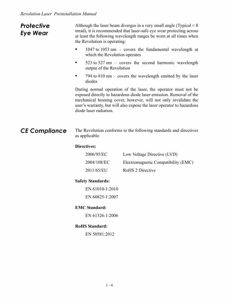
Protective Eye Wear
Although the laser beam diverges in a very small angle (Typical < 8 mrad), it is recommended that laser-safe eye wear protecting across at least the following wavelength ranges be worn at all times when the Revolution is operating:
• 1047 to 1053 nm – covers the fundamental wavelength at which the Revolution operates
• 523 to 527 nm – covers the second harmonic wavelength output of the Revolution
• 794 to 810 nm – covers the wavelength emitted by the laser diodes
During normal operation of the laser, the operator must not be exposed directly to hazardous diode laser emission. Removal of the mechanical housing cover, however, will not only invalidate the user’s warranty, but will also expose the laser operator to hazardous diode laser radiation.
CE Compliance The Revolution conforms to the following standards and directives as applicable:
Directives:
2006/95/EC Low Voltage Directive (LVD)
2004/108/EC Electromagnetic Compatibility (EMC)
2011/65/EU RoHS 2 Directive
Safety Standards:
EN 61010-1:2010
EN 60825-1:2007
EMC Standard:
EN 61326-1:2006
RoHS Standard:
EN 50581:2012
1 - 4

Laser Safety
CDRH Compliance
The safety features listed below have been incorporated into the Revolution to conform to Federal performance standards, as required by 21 CFR 1040.10(h)(1)(iv). Any modification or use of the Revolution that changes, disables, or overrides the function of the engineering controls and safety features invalidates the Class IV certification of the laser described in this manual.
Waste Electrical and Electronic Equipment (WEEE, 2002)
The European Waste Electrical and Electronic Equipment (WEEE) Directive (2002/96/EC) is represented by a crossed-out garbage container label. The purpose of this directive is to minimize the disposal of WEEE as unsorted municipal waste and to facilitate its separate collection.
Keyswitch A separate keyswitch is provided to enable power to the laser. The key cannot be removed from the switch except in the Off position. This assures that use of the laser by unauthorized or unqualified personnel can be prevented.
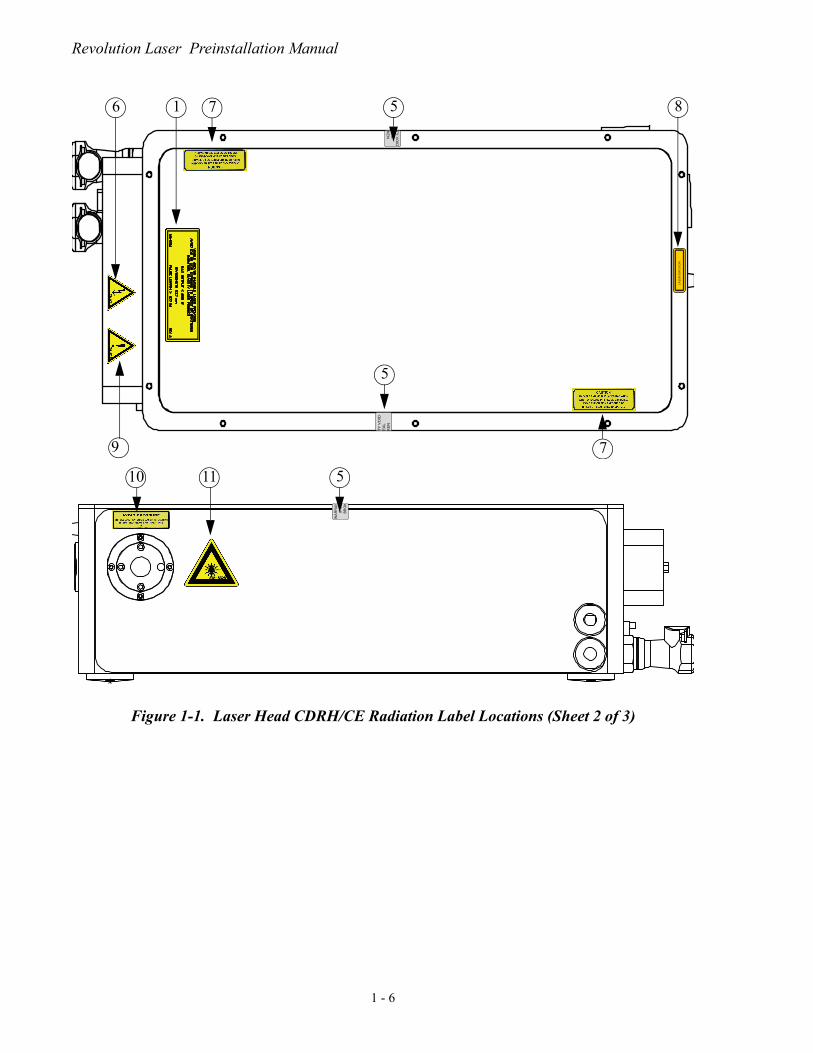
Warning Labels Certification and warning labels are affixed to the Revolution to verify compliance with 21 CFR 1040, to provide information on the wavelength and power emitted, and to warn the user against acci-dental exposure to laser radiation. The location and type of warning logotype labels used on the Revolution laser head and the laser power supply, are shown in Figure 1-1, Table 1-1, Figure 1-2, Table 1-2 respectively.
Figure 1-1. Laser Head CDRH/CE Radiation Label Locations (Sheet 1 of 3)
WA
RR
AN
IF S
BR
O
1 2 3 4 5
1 - 5
Revolution Laser Preinstallation Manual
Figure 1-1. Laser Head CDRH/CE Radiation Label Locations (Sheet 2 of 3)
LASE
R EM
ISSI
ON
TY
VO
IDE
AL
KE
N
TY
VO
IDE
AL
KE
N
576 1 8
9
5
7
WA
RR
AN
IF S
EB
RO
K
510 11
1 - 6

Laser Safety
Figure 1-1. Laser Head CDRH/CE Radiation Label Locations (Sheet 3 of 3)
1011
12
1 - 7

Revolution Laser Preinstallation Manual
Table 1-1. Laser Head CDRH/CE Radiation Labels (Sheet 1 of 2)
ITEM LABEL DESCRIPTION
1
Explanatory Label
2
China RoHS & WEEE Label, Laser Head
3
Identification Label
4
CE Label
5
Warranty Void Label. Warranty void if broken.
6
High Voltage Label
7
Caution Label
WARRANTY VOIDIF SEALBROKEN
1 - 8

Laser Safety
8Laser Emission Label
9
Caution. See Operator’s Manual Label
10
Laser Output Aperture Label
11
Hazardous Radiation Warning Label
12
Interlock Defeat Label
Table 1-1. Laser Head CDRH/CE Radiation Labels (Sheet 2 of 2)
ITEM LABEL DESCRIPTION
LASER EMISSION
808-5269
1 - 9

Revolution Laser Preinstallation Manual
REVOLUTION POWER SUPPLY, REAR PANEL
REVOLUTION POWER SUPPLY, REAR & SIDE PANEL
Figure 1-2. Power Supply CDRH/CE Radiation Label Locations
1 2
3 4 5 6
7
8
Rear Panel
Side Panel
1 - 10

Laser Safety
Table 1-2. Power Supply CDRH/CE Radiation Labels
ITEM LABEL DESCRIPTION
1
Electric Shock Warning Label
2
Grounding Label
3
High Voltage Label
4
Caution Label
5
CE Label
6
Max Current Label
1 - 11

Revolution Laser Preinstallation Manual
7
Identification Label
8
China RoHS & WEEE Label, Power Supply
Table 1-2. Power Supply CDRH/CE Radiation Labels (Continued)
ITEM LABEL DESCRIPTION
1 - 12

Laser Safety
Remote Interlock Connector
The remote interlock connector at the back of the power supply cabinet (marked INTERLOCK) must be used to connect an external CDRH interlock (such as a switch on the door to the laser room). The interlock circuit will then terminate laser action automatically if the door is opened to the laser operating area. To connect the inter-lock switch, remove the supplied external jumper plug, and either re-wire according to the wiring diagram in Figure 1-3, or use a similar connector. Wire the external interlock switch normally closed, such that if the door or safety device and the switch opens, the power supply will immediately turn the laser diodes off. This is a safety precaution to prevent any unaware personnel from inadver-tent exposure to laser radiation.
The interlock function causes the diodes to switch off when the interlock contacts are opened. Lasing can only be resumed by closing the external interlock circuit contacts and cycling the keyswitch to clear the interlock function. The laser must not be oper-ated unless the remote interlock function is in use.
Protective Housings
The laser beam path is contained within the mechanical housing of the laser head until it exits at the front (or side) output port. The diode-pumped head is also contained within this housing to shield the user from stray laser diode light and to protect the laser diodes from exposure to dust and electrostatic discharge.
Cover Safety Interlocks
Interlock micro-switches are used to ensure that the Revolution cannot be operated if the machined metal cover protecting the optical cavity is not in place. The switches turn off the laser diode current if the cover is removed. The cover requires a tool to remove. It is intended to be opened only by Coherent Inc. certified service personnel.
Figure 1-3. External Interlock Connector (Revolution Power Supply)
1 - 13

Revolution Laser Preinstallation Manual
WARNING! Do not operate the Revolution with any covers removed, except when absolutely necessary while performing required service. Operation without the covers may expose the user to hazardous voltages and laser radiation, and also increases the rate of optical surface contamination. Unauthorized removal of the cover protecting the optical cavity will void the warranty.
Emission Indicators
After issuing a START command, an emission indicator lights at the laser head to warn that the laser is about to emit laser radiation.
All emission indicators remain on as long as the laser is capable of lasing. The indicators illuminate a few seconds prior to actual emis-sion to give nearby personnel time to prepare for laser radiation emission.
Beam Safety Shutter
A solenoid-actuated safety shutter is mounted in the optical cavity to interrupt laser action when necessary. The shutter is actuated when the laser is turned on (either by pressing the ON button or by issuing a software command). The interlock fault and fail-safe mode is the closed position.
Location of Controls
Controls for operation of the Revolution laser are accessed through the control software via RS-232 control so operators are not exposed to laser radiation during operation of the laser. If the software is terminated, the computer malfunctions, or the RS-232 connection is broken, the Revolution will stop lasing within three seconds.
Operating Instructions
This manual contains instructions for operating and maintaining the Revolution safely.
CDRH Requirements for Operating via RS-232 Software Commands
The Revolution and power supply comply with all applicable CDRH safety standards when operated via commands sent to the RS-232 port on the front of the power supply cabinet. A software indicator indicates that laser energy is present or can be accessed.
1 - 14
Laser Safety
Maintenance Required to Keep Laser in CDRH Compliance
This section presents the maintenance required to keep this laser product in compliance with CDRH Regulations.
This laser product complies with Title 21 of the United States Code of Federal Regulations, Chapter 1, Subchapter J, Parts 1040.10 and 1040.11, as applicable. To maintain compliance, verify the operation of all features listed below, either annually or whenever the product has been subjected to adverse environmental conditions (e.g., fire, flood, mechanical shock, spilled solvents). This maintenance is to be performed by the user, as outlined below.
• Verify that all the warning labels listed in Figure 1-1 to Figure 1-2, Revolution Radiation Control Drawings, are present and firmly affixed in the correct locations.
• Verify that removing the user interlock connector on the back panel of the power supply prevents laser operation. Figure 1-3 shows the interlock with the jumper plug in place.
• Verify that the time delay between turn-on of the emission indicator and start of laser emission gives enough warning to allow action to avoid exposure to laser radiation.
• Verify that the internal beam attenuator (shutter):
• Operates properly when the laser is turned off from the remote computer controller
• Closes when the keyswitch is turned off
• Blocks access to laser radiation
1 - 15

Revolution Laser Preinstallation Manual
Sources of Additional Information
The following are some sources for additional information on laser safety standards and safety equipment and training.
Laser Safety Standards
Equipment and Training
Safe Use of Lasers Document Z136.1 American National Standards Institute (ANSI) www.ansi.org
Guidelines for Laser Safety and Hazard Assessment Directives PUB 8-1.7 Occupational Safety and Health Administration (OSHA) U.S. Department of Labor www.osha.gov
A Guide for Control of Laser Hazards American Conference of Governmental and Industrial Hygienists (ACGIH) www.acgih.org
Laser Safety Guide Laser Institute of America www.lia.org
Laser Focus Buyer’s Guide Laser Focus World www.laserfocusworld.com
Photonics Spectra Buyer’s Guide Photonics Spectra www.photonics.com
1 - 16

Description and Specifications
SECTION TWO: DESCRIPTION AND SPECIFICATIONS
Introduction The Revolution is a diode-pumped, intra-cavity doubled, Q-switched Nd:YLF laser of 527nm. It is ideal for pumping high-power Ti:Sapphire amplifiers and for materials processing. The Revolution represents a significant advance in this class of laser, offering the high efficiency, low maintenance, and excellent beam quality afforded by laser diode pumping.
The Revolution laser system comprises four main elements:
• Laser head assembly
• Power supply assembly
• Control computer
• Closed loop chiller
Figure 2-1. Revolution Laser Head
2 - 1

Revolution Laser Preinstallation Manual
Laser Head Assembly
The Revolution optical laser head is a sealed monolithic chassis, containing integrated opto-mechanical, electrical, and cooling assemblies, including:
• A diode-pumped, water-cooled, Nd:YLF laser head (pump chamber)
• An optical resonator
• An acousto-optical Q-switch
• A LBO frequency-doubling crystal in a temperature- controlled oven
• Safety shutter
Power Supply Assembly
The power supply assembly includes a master control board and all the electronics to drive the laser diodes, stabilize the temperature of the LBO crystal, Q-switch the laser, and monitor interlocks. The power supply cabinet connects to the laser head through a removable 3-meter umbilical cable. The power supply contains:
• Diode power supply
• LBO temperature controller
• Q-Switch driver
• Accessory electronics
Control Computer
The Revolution comes with a commercial laptop computer and proprietary software to control and monitor the functions of the laser via a RS-232 interface. Because of frequent changes in the avail-ability of specific computer models, the particular computer deliv-ered with each laser may vary in brand and features, but in general it will have a Pentium class processor > 400 MHz, > 32 MB of RAM, >2 GB hard drive, and a CD-ROM. The control software for the Revolution is pre-installed and tested with each laser, and is also delivered on CD-ROM.
This computer is intended to function only as a controller for the Revolution laser. No other software should be loaded or run on this computer as doing so may interfere with the control of the laser.
2 - 2

Description and Specifications
Closed-Loop Chiller
A closed-loop chiller is included to dissipate the waste heat gener-ated and maintain the wavelength of the laser diodes to ensure maximum absorption of the pump light in the gain medium. The chiller has two hoses with quick-release connectors, a water filter, and an internal pressure regulator valve to reduce the water pressure at the laser head.
NOTICE! Use only Optishield II (1 pint) diluted with distilled water (as needed to fill the chiller tank) in the chiller to prevent algae growth and corrosion in the water system.
Block Diagram
Remote Interlock Connector
The remote interlock connector (marked 'INTERLOCK') at the back of the power supply cabinet must be used to connect an external CDRH interlock (such as a switch on the door to the laser room, for example). The interlock circuit will then terminate laser action auto-matically if anyone enters the laser operating area. To connect the interlock switch, remove the external jumper plug supplied, and either re-wire according to the wiring diagram in Figure 2-3 or use a similar connector. Wire the external interlock switch 'normally closed', so that when the door or safety device opens and the switch opens, the power supply will immediately turn off the laser diodes as a safety precaution, and prevent any unaware personnel from inadvertent exposure to laser radiation.
The interlock function causes the diodes to switch off when the interlock contacts are opened. Lasing can only be resumed by closing the external interlock circuit contacts and then cycling the key switch to clear the interlock function. The laser should not be operated unless the remote interlock function is in use.
2 - 3

Revolution Laser Preinstallation Manual
Figure 2-2. Connection Block Diagram
Figure 2-3. External Interlock Circuit Diagram
220VAC12A
50Hz/60Hz
RF BNC
Water OutWater In
115VAC10A/5A
50Hz/60Hz
Notebook Computer
4-Pin Diode
Revolution Power Supply
9-Pin External Interlock
Revolution Laser Head
Chiller
RS 232 to USB
26-Pin Control
J3 J1
Door Switch
2 - 4

Description and Specifications
Specifications & Environmental Requirements
Reference product data sheet available at http://www.coherent.com for specifications. See Table 2-1 for environmental requirements.
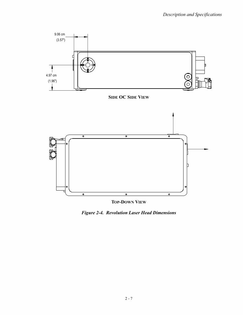
Dimensions Reference Table 2-2, Figure 2-4, and Figure 2-5 for dimensions, weight, and line drawings.
Table 2-1. Environmental Requirements
PARAMETER REQUIREMENT
Ambient Operating Temperature: Laser Head Power Supply
18º C to 28º C
Relative Humidity 40 to 60 % (Non-Condensing)
Altitude Sea Level to 10,000 ft. (3,000 m)
Table 2-2. Dimensions & Weight
LENGTH WIDTH HEIGHT WEIGHT
LASER HEADA 60.62 cm (23.87 in) 21.59 cm (8.5 in) 14.03 cm (5.52 in)19.5 kg
(43 lbs)
POWER SUPPLY 43.68 cm (17.20 in) 48.26 cm (19.00 in) 13.25 cm (5.22 in) 14 kg (31 lbs)
a. Measurements include handles.
2 - 5

Revolution Laser Preinstallation Manual
FRONT VIEW
REAR VIEW
Figure 2-4. Revolution Laser Head Dimensions
5.07 cm(2.00")
10.80 cm(4.25")
9.06 cm(3.57")
12.07 cm(4.75")
21.59 cm(8.50")
14.03 cm(5.52")
2 - 6
Description and Specifications
SIDE OC SIDE VIEW
TOP-DOWN VIEW
Figure 2-4. Revolution Laser Head Dimensions
4.97 cm(1.96")
9.06 cm(3.57")
2 - 7

Revolution Laser Preinstallation Manual
PLAIN SIDE VIEW
Figure 2-4. Revolution Laser Head Dimensions
43.18 cm(17.00")
48.79 cm(19.21")
46.36 cm(18.25")
2 - 8

Description and Specifications
Figure 2-5. Revolution Power Supply Dimensions
48.26cm19.00in
1 cm5. in
43.68cm17.20in
44.45cm17.50in
2 - 9

Revolution Laser Preinstallation Manual
2 - 10

Installation and Utility Requirements
SECTION THREE: INSTALLATION AND UTILITY REQUIREMENTS
Location and Environment
Before installation, select a suitable location for the Revolution. The Revolution is constructed using a temperature-stabilized monolithic body, but Coherent recommends that the laser be located in a labo-ratory-type environment that is free from dust and drafts, with humidity range within 40-60% (non-condensing) and does not exhibit temperature fluctuations greater than ± 5°C.
The environmental rating of the altitude for laser operation must be below 10,000 feet and for non-operating laser must be below 25,000 feet.
Required Utilities The Revolution system requires the utilities listed in Table 3-1.
NOTICE! Do not apply AC power to the power supply chassis; this will activate the LBO crystal heater. Programming the crystal heater improperly will permanently damage the crystal. Such damage will not be covered under warranty.
WARNING! The Revolution power supply is compatible with 200-240 VAC and 50-60 Hz frequency. Do not attempt to operate the Revolu-tion at a different voltage or frequency without consulting with an authorized service representative.
Table 3-1. Revolution Utility Requirements
PARAMETER REQUIREMENT
Cooling:
Laser Head Controller
Closed-loop water coolingAir-cooled with ambient air
3 - 1

Revolution Laser Preinstallation Manual
3 - 2
Controller AC Voltage 200-240 VAC, 50-60 Hz, 9 A Max
Air-Cooled Chiller AC Voltage
220 VAC (± 10 %), 50 Hz, 12 A Max
OR
220 VAC (± 10 %), 60 Hz, 12 A Max
Water-Cooled Chiller AC Voltage (Figure 3-1)
220 VAC (± 10 %), 50 Hz, 12 A Max
OR
220 VAC (± 10 %), 60 Hz, 12 A Max
Power Cord (Figure 3-2)
Certified 3-conductor power cord, 16 AWG.
< 10 ft (3 m) length and rated for 10 A minimum.
The Controller power cord provided in the ship-kit is rated for 1625 W.
Table 3-1. Revolution Utility Requirements
PARAMETER REQUIREMENT
Figure 3-1. Chiller AC Voltage Cable

Installation and Utility Requirements
•
Use standard table screws (M6 or ?-20) on the two slots located at the edge of the front and back of the laser housing to secure the laser head to the table.
Figure 3-2. Revolution Power Supply Cable
3 - 3

Revolution Laser Preinstallation Manual
3 - 4

Parts List
PARTS LIST
The following parts can be ordered by contacting our Technical Support Hotline at 1-800-367-7890 (1-408-764-4557 outside the U.S.); through E-mail ([email protected]); or your local Coherent service representative.
Table A-1. List of Parts
DESCRIPTION PART NUMBER
REVOLUTION SYSTEM
Computer Laptop 1128466
Interlock Jumper, Power Supply 1102346
Removable knobs (qty 3) 400-0989
REVOLUTION CHILLERS & ACCESSORIES
Corrosion Inhibitor, Optishield II 400107
Poly Science Water Filter, 5µ, 2.5 in. Diameter x 9.875 in. length 1166401
Chiller, Turbine Pump, Air-Cooled Condenser, Single Phase, 1500W Cooling Capacity @ 240VAC/50Hz
1234950
Chiller, Turbine Pump, Air-Cooled Condenser, Single Phase, 1800W Cooling Capacity @ 208/230VAC/60Hz, or 1500W Cooling Capacity @ 200VAC/50Hz
1234960
Chiller, Turbine Pump, Water-Cooled Condenser, Single Phase, 1550W Cooling Capacity @ 240VAC/50Hz
1235050
Chiller, Turbine Pump, Water-Cooled Condenser, Single Phase, 1850W Cooling Capacity @ 208/230VAC/60Hz, or 1550W Cooling Capacity @ 200VAC/50Hz
1235060
Parts List- 1

Revolution Laser Preinstallation Manual
Parts List- 2

Glossary
GLOSSARY
°C Degrees centigrade or Celsius°F Degrees Fahrenheitµ Micronsµrad Microradian(s)µsec Microsecond(s)1/e2 Beam diameter parameter
A AmperesAC Alternating currentAGC Automatic gain control
BPF Band pass filter
CDRH Center for Devices and Radiological Healthcm Centimeter(s)CW Continuous wave
DC Direct current
EMC Electromagnetic compliance
GHz Gigahertz
Hz Hertz
IR Infrared
kg Kilogram(s)kHz Kilohertz
LED Light emitting diodeLVD Low voltage directive
m Meter(s)mA Milliampere(s)MHz Megahertzmm Millimeter(s)mrad Milliradian(s)msec Millisecond(s)mV Millivolt(s)mW Milliwatt(s)
Nd:YLF Neodymium doped yttrium Lithium Fluoridenm Nanometer(s)
OEM Original equipment manufacturer
PZT piezo-electric transducer
Glossary - 1

Revolution Laser Preinstallation Manual
RF Radio frequencyrms Root mean squareRx Receive
TEM Transverse electromagnetic (cross-sectional laser beam mode)Tx Transmit
VAC Volts, alternating currentVDC Volts, direct current
W Watt(s)
Glossary - 2

Index
INDEX
BBeam safety shutter 1-13
CCDRH
Compliance 1-5Requirements 1-13
Closed loop chiller 2-3Control computer 2-2Cover safety interlocks 1-12
DDimensions 2-5
Power supply 2-9
EEmission indicators 1-13Equipment and Training 1-15Export Control Laws Compliance viEye wear, protective 1-4
HHazards 1-1
IInstallation
Location 3-1Power supply 3-2
Interlocks, safety 1-12
KKeyswitch 1-5
LLabels
Warning 1-5Laser 2-2Laser Head Assembly 2-2Laser safety 1-1Location of controls 1-13Location, installation 3-1
MMaintenance
Required to keep laser in CDRH compliance 1-14Requirements 1-14
OOperating instructions 1-13Output port shutter 1-13
PParts list A-1Power supply
Assembly 2-2Dimensions 2-9
Protective eye wear 1-4Protective housings 1-12
RRemote interlock connector 1-12Requirements
CDRH 1-13Installation 3-1Maintenance 1-14Utility 3-1
SSafety
Eye wear 1-4Interlocks 1-12Keyswitch 1-5Laser 1-1Warning labels 1-5
Specifications 2-5
UUtility requirements 3-1
WWarning labels 1-5
Index - 1

Revolution Laser Preinstallation Manual
Index - 2


Revolution Laser Preinstallation Manual © Coherent, Inc. 2/2016, (RoHS) Printed in the U.S.A. Part No.1299437, Rev AA


Revolution Laser Preinstallation Manual©Coherent Inc., 2/2016 (RoHS), printed in the USAPart No. 1299437 Rev. AA