revolutionary computational aerosciences (rca) · revolutionary computational aerosciences (rca)...
TRANSCRIPT

1
Transformational Tools and Technologies Project
Revolutionary Computational Aerosciences
(RCA)
Mujeeb R. Malik Technical Lead, RCA
NASA Langley Research Center
Hampton, VA
AIAA SciTech 2016 San Diego, CA
January 4-8, 2016
https://ntrs.nasa.gov/search.jsp?R=20160007667 2018-06-06T17:57:54+00:00Z

2
Outline
Revolutionary Computational Aerosciences (RCA)
• Relevance and Vision
• Technical Challenge
• Research Portfolio
• Research Highlights
• Summary

3
Aeronautics Research Mission Directorate
Advanced Air
Transport Technology
(AATT)
Advanced Air
Vehicles (AAVP)
Airspace Operations
And Safety (AOSP)
Integrated Aviation
Systems (IASP)
NASA Aeronautics Program Structure
Transformative Aeronautics
Concept (TACP)
Revolutionary Vertical
Lift Technology
(RVLT)
Commercial Supersonic
Technology
(CST)
Advanced Composites
(ACP)
Aeronautics Evaluation
and Test Capabilities
(AETC)
Airspace Technology
Demonstration
(ATD)
SMART NAS – Testbed
for Safe Trajectory
Operations
Safe Autonomous
System Operations
(SASO)
Environmentally
Responsible
Aviation
(ERA)
UAS Integration
in the NAS
Flight Demonstration
and Capabilities
(FDC)
Leading Edge
Aeronautics Research
for NASA
(LEARN)
Transformational Tools
and Technologies
(TTT)
Convergent Aeronautics
Solutions
(CAS)
-------------------------- Mission Programs ----------------------------- Seedling Program

4
NASA ARMD SIP and Strategic Thrusts
Safe, Efficient Growth in Global Operations • Enable full NextGen and develop technologies to substantially
reduce aircraft safety risks
Innovation in Commercial Supersonic Aircraft • Achieve a low-boom standard
Ultra-Efficient Commercial Vehicles • Pioneer technologies for big leaps in efficiency and
environmental performance
Transition to Low-Carbon Propulsion • Characterize drop-in alternative fuels and pioneer
low-carbon propulsion technology
Real-Time System-Wide Safety Assurance • Develop an integrated prototype of a real-time safety
monitoring and assurance system
Assured Autonomy for Aviation Transformation • Develop high impact aviation autonomy applications
T3 Project develops cross-cutting tools and technologies
Primary
areas of
project
emphasis
Primary
area of
RCA
emphasis

5
Transformational Tools & Technologies (T3)
Project Management Structure P
RO
JE
CT
LE
VE
L
Project - Center Liaisons: Mike Rogers (ARC) Jeff Bauer (AFRC)
Laura Stokley (GRC) Melinda Cagle (LaRC)
Business Lead – Debra Findley (GRC) Center Analysts – Cecelia Town (ARC)
Lisa Logan (AFRC) Joe Sessa (GRC)
Renee’ Williams (LaRC) NRA Manager – Renee’ Williams (LaRC)
Scheduler – Joyce Moran (GRC)
Executive Team: Project Manager – Mike Rogers (Acting, ARC) Deputy Project Manager – Rob Scott (LaRC)
Associate Project Manager – Dale Hopkins (Acting, GRC)
Revolutionary Tools & Methods (RTM)
SPM – Melinda Cagle (LaRC)
Sub-Project Technical Leads:
RCA – Mujeeb Malik (LaRC)
Combustion Modeling – Jeff Moder (GRC)
MDAO/SA – Jeff Viken (LaRC)
M&S Modeling – Dale Hopkins (GRC)
SU
B-P
RO
JE
CT
Critical Aeronautics Technologies (CAT)
SPM –Laura Stokley (GRC)
Sub-Project Technical Leads:
M&S Technologies – Dale Hopkins (GRC)
iMeasurements – Tom Jones (LaRC)
Propulsion Controls – Dennis Culley (GRC)
Flight Controls – Jay Brandon (LaRC) and Joe Pahle (AFRC)
Combustion Technologies – Jeff Moder (GRC)
Development of critical aeronautics technologies
that can enable revolutionary improvement
in aircraft system design. Innovative ideas that may lead to patentable results.
Current Technical Challenge to develop 2700F-capable engine materials by 2017.
Development of revolutionary
comprehensive physics-based aeronautics analysis and design
capability. Philosophically based on
Vision 2030 study recommendations. Current Technical
Challenge to reduce CFD error by 40% by 2017.
Tools for fast, efficient design & analysis of advanced aviation systems &
cross-cutting technologies

6
CFD Vision 2030 Study
• NASA commissioned a one-year study to develop a comprehensive and enduring vision of future CFD technology:
− HPC
− Physical Modeling
− Numerical Algorithms
− Geometry and Grid Generation
− Multidisciplinary Analysis and Optimization
• Wide community support for the research roadmap:
− Aerospace America, Aviation Week & Space Technology
− AIAA Aviation 2014 Panel Discussion
− Independent Activities/Forums
NASA CR 2014-218178
Report (published March 2014) available at: http://ntrs.nasa.gov/archive/nasa/casi.ntrs.nasa.gov/20140003093.pdf

7
Vision of CFD in 2030
Emphasis on physics-based, predictive modeling • Transition, turbulence, separation, chemically-reacting flows, radiation, heat
transfer, and constitutive models, among others.
Management of errors and uncertainties • From physical modeling, mesh, natural variability, lack of knowledge in the
parameters of a particular fluid flow problem, etc.
A much higher degree of automation in all steps of the analysis
process
• Geometry creation, meshing, large databases of simulation results, extraction and
understanding of the vast amounts of information generated with minimal user
intervention.
Ability to effectively utilize massively parallel HPC architectures that
will be available in the 2030 time frame
• Capacity- and capability-computing tasks in both industrial and research
environments.
Seamless integration with multi-disciplinary analyses
• High fidelity CFD tools, interfaces, coupling approaches, etc.
Predictive and automated physics-based tools required for timely analysis/design of novel configurations.

8
Grand Challenge Problems
• Represent critical step changes in engineering
design capability
• May not be routinely achievable by 2030
• Representative of key elements of major NASA
missions (ARMD, HEOMD and STMD)
1. Large Eddy Simulation (LES) of a powered aircraft
configuration across the full flight envelope
2. Off-design turbofan engine transient simulation
3. Multi-Disciplinary Analysis and Optimization (MDAO) of
a highly-flexible advanced aircraft configuration
4. Probabilistic analysis of a powered space access
configuration

9
Technology Development Roadmap
Visualization
Unsteady, complex geometry, separated flow at
flight Reynolds number (e.g., high lift)
2030202520202015
HPCCFD on Massively Parallel Systems
CFD on Revolutionary Systems
(Quantum, Bio, etc.)
TRL LOW
MEDIUM
HIGH
PETASCALE
Demonstrate implementation of CFD
algorithms for extreme parallelism in
NASA CFD codes (e.g., FUN3D)
EXASCALE
Technology Milestone
Demonstrate efficiently scaled
CFD simulation capability on an
exascale system
30 exaFLOPS, unsteady,
maneuvering flight, full engine
simulation (with combustion)
Physical Modeling
RANS
Hybrid RANS/LES
LES
Improved RST models
in CFD codes
Technology Demonstration
Algorithms
Convergence/Robustness
Uncertainty Quantification (UQ)
Production scalable
entropy-stable solvers
Characterization of UQ in aerospace
Highly accurate RST models for flow separation
Large scale stochastic capabilities in CFD
Knowledge ExtractionOn demand analysis/visualization of a
10B point unsteady CFD simulation
MDAO
Define standard for coupling
to other disciplines
High fidelity coupling
techniques/frameworks
Incorporation of UQ for MDAO
UQ-Enabled MDAO
Integrated transition
prediction
Decision Gate
YES
NO
NO
Scalable optimal solvers
YES
NODemonstrate solution of a
representative model problem
Robust CFD for
complex MDAs
Automated robust solvers
Reliable error estimates in CFD codes
MDAO simulation of an entire
aircraft (e.g., aero-acoustics)
On demand analysis/visualization of a
100B point unsteady CFD simulation
Creation of real-time multi-fidelity database: 1000 unsteady CFD
simulations plus test data with complete UQ of all data sources
WMLES/WRLES for complex 3D flows at appropriate Re
Integrated Databases
Simplified data
representation
Geometry and Grid
Generation
Fixed Grid
Adaptive Grid
Tighter CAD couplingLarge scale parallel
mesh generationAutomated in-situ mesh
with adaptive control
Production AMR in CFD codes
Uncertainty propagation
capabilities in CFD
Grid convergence for a
complete configuration
Multi-regime
turbulence-chemistry
interaction model
Chemical kinetics
in LESChemical kinetics
calculation speedupCombustion
Unsteady, 3D geometry, separated flow
(e.g., rotating turbomachinery with reactions)

10
The Way Forward
• Study recommendations requiring additional investment:
− Access to HPC for “capability” computing
− Validation experiments − Juncture Flow, THX, NRA: separation, compressible free shear layer
− Collaborations with academia/research institutes − 17 new NRA awards in Vision 2030 areas of RCA, MDAO, and Combustion (including mesh generation)
− Solution adaptive grids (human out of the loop)
− High-fidelity multidisciplinary analysis and design optimization − NRA awarded
− Software development infrastructure/frameworks
• Collaborations will aim to solve Grand Challenge Problems – NRA evaluating wall-modeled LES of realistic configurations
− Suggested by the CFD Vision 2030 Study
− Others chosen in consultation with ARMD projects
− Opportunity for “Centennial Challenge”-like awards

11
Technical Challenge Identify and downselect critical turbulence, transition, and
numerical method technologies for 40% reduction in
predictive error against standard test cases for turbulent
separated flows, evolution of free shear flows and shock-
boundary layer interactions on state-of-the-art high
performance computing hardware.
Technical Areas and Approaches • Development of more accurate physics-based methods
(e.g. higher moment closure, large eddy simulation (LES))
• Advanced numerical methods
• Transition prediction and modeling
• Validation experiments
• Multidisciplinary analysis and design (high fidelity)
Benefit/Pay-off • Capability will be used by the aeronautics community to
improve designs and reduce design cycle times.
• Facilitates accelerated introduction of advanced air.
vehicles and propulsion systems into the airspace system.
• Supports ARMD Strategic Thrusts # 2, 3 and 4.
Revolutionary Computational Aerosciences
Technical Challenge: Physics-Based Turbulence Models & Simulations

12
RCA Research Team
• NASA Centers: Ames, Glenn and Langley − Computational and Experimental Research
• Industrial/Other Government Stake Holders − Technical Interchange Meetings to discuss technical areas of mutual interest
• Engage Academia via NRAs − 12 NRAs completed
− 8 New awarded
3 Turbulence simulations
2 Numerical Methods
1 Paralell Mesh Generation
2 Validation Experiments

13
RCA “Standard” Test Cases for Turbulence
Modeling
• RCA TC Requires 40% error reduction in turbulent flow predictions
• Define “standard” test cases to enable quantification of prediction improvement
• Primary test cases − NASA 2D hump − Axisymmetric transonic bump − 2D shear layer
− Axisymmetric jet − Axisymmetric compression corner
• Secondary test cases − ONERA M6 − FAITH − NACA 4412 at AoA
− 2-D Wake Flow − ---
• New CFD Validation Experiments
Separation and Reattachment
Locations for NASA 2D Hump
Centerline Velocity Profiles for
NASA M=0.9 Cold Jet

14
Implementation and Evaluation of Full Reynolds
Stress Models
ONERA M6 pressure
coefficient at 90% span
station; alpha=4.08 deg case
• Full Reynolds Stress Models Implemented in NASA CFD Code, FUN3D
− 7 equations vs. 1 or 2 equations DLR’s SSG/LRR-RSM-w2012 WlicoxRSM-w2006
• No improvement in prediction of flow separation over simpler (SA/SST) models
− NASA Wall-mounted Hump, − Axis-symmetric Transonic Bump (not shown) − ONERA M6
• Some evidence that corner flow separation will be better predicted
− Juncture flow experiment will provide data to test out the hypothesis
• Research needed to strengthen weak links − Pressure/strain correlation − Length scale equation
Results for NASA wall-mounted hump

15
2-Equation Model with Improved Length Scale
• Length scale equation the weakest link in 2-
equation turbulence modeling
− Menter’s modification to Rotta’s two equation
(K-kL) model
− Abdol-Hamid’s improvement of Menter’s
model K-kL-MEAH2015 implemented in FUN3D (NASA/TM-
2015-218968)
Additional modifications for jet flow (K-kL+J) and
temperature effects (K-kL+J+Mu)
• Much improved flow predictions
− Axisymmetric Transonic Bump Error in separation length reduced from 28% (SST) to
8%
− Cold and Hot Jets Significant improvement in CL velocity prediction
Prediction of
Flow
Separation for
Transonic
Bump
Comparisons of turbulence models
results for hot subsonic jet (Bridge’s
M=0.376; sp23)
Comparisons of turbulence models
results for cold subsonic jet (Bridge’s
M=0.5; sp3)
Data Experiment K-kL SST
Separation Location 0.70 0.68 0.65
Reattachment Location 1.10 1.11 1.16
Bubble Size Error (%) 7.50 27.5

16
Large Eddy Simulation (LES)
• Two of the Grand Challenge Problems Require Use of LES
• The challenge is How to Reduce Cost? − Wall-modeled LES − Hybrid RANS/LES Approach
− Speedup by using advanced numerical methods
• Recent/ongoing/future LES efforts − High-Lift Configuration (30P/30N) − RCA standard test cases − Common Research Model
A first step towards GC Problem #1
No-slip LES
Equilibrium WM
Exp.
NASA Hump: Flow reattaches at X/C = 1.1 in experiment and WMLES
WMLES of 30P/30N

17
DNS of Turbulent Smooth-wall Separation
• Produce high-fidelity data for smooth-wall separation
− Use it to diagnose limitation of RANS and hybrid RANS/LES methods
− Improve RANS models
• Example DNS currently underway − Coleman, Spalart, Rumsey − Fully spectral method with 2 billion points − Induce separation on a flat plate by imposing a
transpiration velocity profile at the top
boundary adverse pressure gradient on a flat-plate
− With and without sweep DNS of separation and reattachment in a turbulent boundary
layer: (a) Mean streamwise velocity U; (b); Reynolds shear stress -<u’v’>; (c) instantaneous skin friction. Re=40000.
Skin friction using RANS and DNS.
(a)
(b)
(c)
U
cf
s
Vmax
Vtop(x)
h
No slip
x
y
Lx
U∞
W∞ = U∞tan L
-u’v’
Cf

18
CFD Validation Experiments - 1
• Juncture Flow Experiment − Prediction of trailing edge corner separation a challenge − Risk reduction experiments to develop final design
• Shock wave/Boundary Layer Interaction − Mach 2.5 Axisymmetric SBLI (attached and separated)
− Mean and turbulent stress data
• Turbulent Heat Flux − Multi-hole film cooling (advanced nozzles and turbines) − Mean and turbulent stress data
Experimental surface flow visualization
• 2D Separation − NRA to Notre Dame (Flint and Corke) − Data for attached and separated (incipient, small,
large) flow
• 2D Mixing Layer − NRA to U-Illinois (Dutton and Elliott) − Full documentation of BC and mean/turbulence data
Corner
separation
Fuselage
side
Wing
Trailing edge
Flow
0.00
0.02
0.04
0.06
0.08
0.10
0.12
35.0 40.0 45.0 50.0 55.0 60.0 65.0
pw
/pt,
0
x (cm)
Upper Taps
Lower Taps
Window Leading Edge
Window Centerline
Window Trailing Edge
1 2 3 4 5 6 7 8 9 10 11 12
Axisymmetric SWBLI – 13.5°Cone Angle 0
0.51
1.52
2.53
3.54
4.55
0 1 23 4 5 6 7 89101112
00.51
1.52
2.53
3.54
4.55
0 1 23 4 5 6 7 89101112
Dq = 30o
U, V
Notre Dame
Model
19
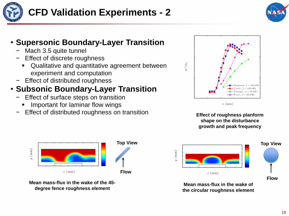
Effect of roughness planform
shape on the disturbance
growth and peak frequency
Mean mass-flux in the wake of
the circular roughness element
Mean mass-flux in the wake of the 45-
degree fence roughness element
Top View Top View
Flow
Flow
CFD Validation Experiments - 2
• Supersonic Boundary-Layer Transition − Mach 3.5 quite tunnel − Effect of discrete roughness Qualitative and quantitative agreement between
experiment and computation − Effect of distributed roughness
• Subsonic Boundary-Layer Transition − Effect of surface steps on transition Important for laminar flow wings
− Effect of distributed roughness on transition

20
• Transition an Initial Boundary Value Problem − External Forcing (roughness, acosutic, turbulence, …)
• Require A Holistic Approach for Transition Prediction
− Use measured free stream disturbance spectra (amplitude/frequency) as BC
− DNS (NPSE) of boundary layer disturbance evolution − Threshold disturbance amplitude ((pamp)T) as indicator for
transition
• Results [Example]
Freestream PSD in the AEDC Tunnel 9.
− Transition in AEDC Hypervelocity Wind:
Mach 10
7 – degree cone
Nose bluntness, Rn = 0.152, 5.08 mm
Different unit Reynolds numbers
− Amplitude based approach provides good
prediction of transition
N factor does not, as free stream forcing
varies
Amplitude of the pressure fluctuations on the
wall generated by the slow acoustic waves.
Holistic Transition Prediction
0 10 20 30 40 50 60 70 80 90 100 110 12010
-5
10-4
10-3
10-2
10-1
100
Re=1.81 m, f=78 kHz 1.E-2
RE=6.30 m, f=240 kHz 2.E-3
Re=15.03 m, f=440 kHz 6.E-4
amp. = 1.4
amp. = 1.8
X (cm)
pw
/p
Cases 1-3
Case XT (cm) N
(pamp)T Expt. (pamp)T PSE
1.4 1.8 1.4 1.8
1 81 84 84 3.2 3.6 4.1
2 33 34 36 5.3 5.7 5.1
3 22 23 25 6.5 6.9 7.0
Predicted and
measured transition
onset points.

21
Advanced Numerical Methods
• High-Order Schemes for Unsteady Flow Simulations − Entropy Stable Spectral Element Framework − Space-Time Discontinuous Galerkin Scheme − Space-Time Conservation-Element/Solution-Element (CESE) Scheme
− Flux Reconstruction (FR) Scheme Subject of next 4 presentations
• Convergence Acceleration − Hierarchical Adaptive Nonlinear Iteration Method (HANIM)
− 2 to 20 times speed up for various test cases
• Grid Adaptation − MIT NRA completed (next 2 slides)
Residuals
Drag
Characteristic grid spacing, h
Sp
ee
du
p
LI- HANIM Speedup relative to
PA method; NACA 0012 airfoil
22
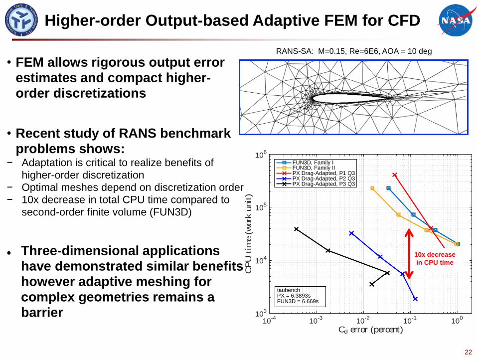
Higher-order Output-based Adaptive FEM for CFD
• FEM allows rigorous output error estimates and compact higher-order discretizations
• Recent study of RANS benchmark problems shows:
− Adaptation is critical to realize benefits of
higher-order discretization − Optimal meshes depend on discretization order − 10x decrease in total CPU time compared to
second-order finite volume (FUN3D)
Three-dimensional applications have demonstrated similar benefits however adaptive meshing for complex geometries remains a barrier
Cd error (percent)10
-410
-310
-210
-110
0
CP
Uti
me
(work
unit
)
103
104
105
106
FUN3D, Family IFUN3D, Family IIPX Drag-Adapted, P1 Q3PX Drag-Adapted, P2 Q3PX Drag-Adapted, P3 Q3
taubenchPX = 6.3893sFUN3D = 6.669s
10x decrease
in CPU time
RANS-SA: M=0.15, Re=6E6, AOA = 10 deg

23
Space-time Adaptive Methods for CFD
Uniform
refinement
Tensor-
product
adaptation
Unstructured
space-time
adaptation
M=0.1, Re = 100 2D
Unstructured space-time adaptation
Final mesh (15th adaptive iteration)
Cd
t
• Higher-order
output-based
adaptive space-
time DGFEM
• Feasibility
demonstration on
2D cylinder flow

24
Combined Uncertainty and Error Bound
Estimates for General CFD Computations
• Excessive numerical errors can render computed uncertainty statistics misleading and meaningless
− Quantify impact of numerical errors on computed uncertainty to provide useful statistics to engineers
• A unified framework for combined uncertainty and a-posteriori error bounds estimates:
− If simulation has no uncertainty, then standard a-posteriori error bound estimates are obtained
− If simulation has no numerical error, then standard uncertainty estimates are obtained
− If simulation has both uncertainty and numerical error, then uncertainty statistics with error bound estimates are obtained
Initial implementation/testing in NASA’s CFD code, OVERFLOW
ONERA M6 wing with uncertain inflow
conditions. Surface pressure statistics at 65%
span location.
Zoom close-up showing uncertainty error
bound estimates for mean and standard
deviation.

25
• FUN3D is used for aircraft/spacecraft analysis and design − Aerodynamics, loads, noise, sonic boom, aeroelastics − New RCA models incorporated/evaluated
FUN3D Refactoring
• Refactor the code − Cleaning out unused, experimental, or poorly implemented code − Framework with distributed control − Isolate common components that are independent of discretization or physics − Easy insertion of multiple discretization schemes and physics models − Provide increased flexibility in coupling with other disciplines, partner with
outside organizations
• Originally for algorithm development • Increased size of team as code
reached production-level capability − Code evolved without shared design principle − Result is awkward dependencies that are
difficult to navigate and maintain
− Difficult to collaborate with outside organizations for multidisciplinary developments

26
• RCA: Foundational research that supports all NASA Missions
• RCA research aimed at advancing the state-of-the art of CFD Accuracy Speed
Robustness/Reliability
• CFD Validation Experiments A Critical Need • Working towards Vision 2030, to enable
− Aircraft certification by analysis − Analysis/design of new aerospace vehicles without wind tunnel testing
Summary

27