rewriting the limits for deep geothermal drilling: direct ...borehole edge that will simultaneously...
TRANSCRIPT

Proceedings World Geothermal Congress 2020
Reykjavik, Iceland, April 26 – May 2, 2020
1
Rewriting the Limits for Deep Geothermal Drilling: Direct Energy Drilling Using Millimeter
Wave Technology
Matt Houde1, Carlos Araque1, Ken Oglesby2, and Paul Woskov3
1Quaise, Inc., 501 Massachusetts Ave., Cambridge, MA 02139; 2Impact Technologies LLC, P.O. Box 35505 Tulsa, OK 74153-
0505; 3MIT Plasma Science and Fusion Center, NW16-110, 167 Albany St, Cambridge, MA 02139
[email protected], [email protected], [email protected]
Keywords: Deep Drilling, Hot Dry Rock, EGS, Supercritical, Millimeter-Wave, Casing-While-Drilling.
ABSTRACT
Vast amounts of energy are stored as heat in dry rock. At depths ranging from 10-20 km, the temperature and pressure reach
supercritical conditions where potential power output is increased significantly compared to conventional geothermal resources.
Supercritical geothermal resources remain untapped, but what if innovations in drilling technology could provide access to
supercritical conditions anywhere on earth and within 100 days? What if exploration risk would no longer be significant because the
incremental costs of drilling deeper would be relatively small and geothermal power could be produced locally, near high-demand
centers? This would forever change the outlook and scalability of geothermal energy as a compelling alternative for countries
transitioning to clean energy, although mechanical drilling methods cannot penetrate these depths and are a mature technology only
capable of incremental improvements.
Technical limitations to deep geothermal drilling could be overcome by direct energy drilling using Millimeter Wave (MMW)
technology. Full bore penetration would be transformed into solely an energy-matter interaction, an entirely new approach that
removes high temperature and high-pressure limits imposed on mechanical tools. MMW drilling has the potential to increase
conventional drilling rates of penetration (ROP) by a factor of 10 or more, enable casing-while-drilling, and access depths up to 10-
20 km. In this paper, we revisit the concept of direct-energy drilling via millimeter waves, pioneered at the MIT Plasma Science
Fusion Center and now on active development at Quaise, Inc., to show the potential and feasibility of this technology both technically
and economically. We use simple models to demonstrate likely rates of penetration, material removal techniques, casing-while-
drilling and economic value, and outline a technology, product, and business development roadmap to get there at scale.
1. INTRODUCTION
The heat flux that continuously emanates through the earth’s crust is estimated at about 5.4*1021 MJ (WEC, 2013). Compared to
annual world energy consumption, 6.1 * 1014 MJ for 2015, extracting just 0.1% of this available energy would be enough to meet
global energy demand for over a million years (EIA, 2017). Despite this enormous potential, only a small fraction of this heat content
makes itself available as conventional geothermal energy, which is a rare occurrence outside of ideal locations near tectonic plate
boundaries. Scaling up geothermal power to meet a significant portion of world energy demand requires development of Enhanced
Geothermal Systems (EGS) technology. Decades of research have gone into the EGS concept but attempts at developing a commercial
EGS power plant have met limited success and have not seen widespread adoption despite the resource potential. Recent efforts have
been focused on exploiting low temperature geothermal resources, by increasing the flow rate with stimulation technologies derived
from the Oil and Gas (O&G) industry. However, the number of wells required result in high drilling costs and the costs of materials
alone could prove uneconomical. The ability to effectively enhance permeability for EGS in shallow crystalline rock is highly site
dependent, so improved techniques may not prove scalable for widespread deployment (Lowry et al., 2017) (Jung, 2013).
An alternative approach is to increase the flow temperature past the critical point of water, where it will enter a supercritical state. At
these temperatures, a geothermal well would generate an order of magnitude more energy compared to a conventional geothermal
well, which could improve the economics for EGS to scale at any location (Friðleifsson et al., 2014). Efforts are already underway in
several countries with experience in geothermal to tap into supercritical geothermal resources overlying shallow magma bodies where
conventional geothermal is already exploited (Dobson et al., 2017). The economics become much more favorable for “supercritical
EGS” if power production can be increased to negate the cost increase for drilling deeper wells.

Houde et al.
2
Figure 1: World contour map showing depths to 450 °C. Approximately 81% of the world’s population has access to
supercritical conditions at <20 km depth, but few locations have a shallow heat source to reach supercritical temperatures at
the shallow drilling depths that are currently economical (Claudohos et al., 2018).
Assuming an average geothermal gradient of 30 °C/km, supercritical temperatures can be reached for most of the world’s population
at depths between 10-20 km (figure 1). Supercritical EGS requires disruptive innovation in two key technology areas: (1) stimulation
methods, that scale to be consistently applicable across a wide range of geologic formations at depths near or at the Brittle-Ductile
Transition (BDT); and (2) cost-effective methods to drill deep for economically attractive temperatures (Claudohos et al., 2018) (DOE
Geovision, 2014). Supercritical EGS can accelerate geothermal beyond a niche source of energy for the world, but only if drilling
technology is also advanced to make drilling depths of 10-20 km economic. New drilling techniques must improve the ROP by an
order of magnitude and achieve a dramatic savings in casing cost to make supercritical EGS practical anywhere.
2. DEEP DRILLING CONSTRAINTS
Significant improvements in conventional drilling technology have been lacking, as mechanical drilling equipment face several
shortcomings in drilling through high temperatures and hard abrasive rock. This includes degradation of mechanical equipment, low
efficiency/Rate of Penetration (ROP), and significant time lost to tripping/fishing the drill string and other repairs to the mechanical
assemblage (GEECO, 2011). The WellCost Lite model predicts well costs of $2,000 - $4,000/m are expected for a 5-km EGS well,
so drilling costs could increase exponentially when attempting to reach supercritical conditions (Tester et al., 2006). In-situ conditions
for supercritical EGS at most locations will be deep and hot enough to exceed the specifications for mechanical drilling tools – the
deepest boreholes in the world have barely exceeded 12 km depth before high temperatures or other limitations were reached.
An innovative solution is directed energy drilling, which would replace mechanical rock destruction method with an energy-matter
interaction: intense energy will melt/vaporize matter and create a propagation path through it, while also having the potential to
replace casing/cementing with a durable vitrified liner produced along the borehole walls. Rock penetration would cease to be limited
by rock hardness and temperature as no mechanical equipment would be required downhole. Directed energy drilling research has
been conducted for over 5 decades, focused on lasers, but the longest penetration achieved to date has not eclipsed 60 cm (Gahan,
2005). Lasers are inefficient (<10%) at high power and their short wavelengths are fundamentally incompatible with the rock
extraction particle flow for long distance transmission through deep boreholes (Nusinovich et al., 2014). An alternative approach is
increase to an optimal wavelength for electromagnetic radiation that can propagate more efficiently over large distances and through
small particulate filed propagation paths.
3. MILLIMETER-WAVE DRILLING
Electromagnetic (non-ionizing) radiation between 30 to 300 GHz has a wavelength of 1-mm to 10-mm, called Millimeter-Waves
(MMW). At these longer wavelengths, electromagnetic radiation avoids Rayleigh scattering and can transfer energy 1012 times more
efficiently through a fine particulate cloud than laser sources. High-powered sources of MMW are available via gyrotrons, a
technology that has been around for over 50 years and developed as part of nuclear fusion research to heat plasmas. Gyrotrons are a
class of free electron masers: a high-voltage electron beam is generated inside a strong magnetic field, causing electrons to gyrate
around magnetic field lines, then efficiently convert the electron beam energy, through electron cyclotron resonance, into powerful
radiation (Nusinovich, 2004). Gyrotrons are much more efficient (50%) than high-power lasers, and several MW-scale units are
currently in use around the world for fusion research, such as the International Thermonuclear Experiment Reactor (Jacquinot, 1998).
Rugged, transportable MW-scale gyrotron systems have been developed for use by the U.S. Department of Defense, so modest
adaptation is required to modify this system for a drilling operation (Blank et al., 2008).

Houde et al.
3
3.1 MMW Drilling Concept
The general concept for MMW Drilling is illustrated in figure 2 (Woskov & Cohn, 2009). High-powered MMW radiation is generated
at the surface by a gyrotron and efficiently guided long distances by both metallic waveguides and the vitrified (glass formed by rock
melt) borehole wall. The only downhole component required is the metallic waveguide (see figure 2), which serves as a conduit for
MMW beam energy, purge gas flow, and remote diagnostics (US Patent #8393410B2, 2013). Rock will absorb the MMW beam,
rapidly raising the surface temperature of the rock to over 3000 °C that will melt or vaporize the rock exposed, depending on power
input and time of exposure (Hagen 1999). The waveguide is kept at a standoff distance from the melt/vaporization front as the MMW
beam is launched, for survivability, and naturally diverges to ream a borehole diameter larger than the waveguide, leaving an annular
space for debris removal of exhaust. MMW directed energy is delivered as a Gaussian beam, with less power absorbed along the
borehole edge that will simultaneously vitrify the borehole wall to provide a liner seal that can stabilize the borehole after cooldown.
The vitrified liner itself will act as a dielectric waveguide to continue propagation of energy to borehole bottom, which could enable
very large standoff distances (> 100 m) between waveguide and vaporization/melting front.
Debris is either vaporized and evacuated up the borehole with the injected purge gas as a nano-particulate smoke: Full Bore
Vaporization); or permeated into adjacent fractures as rock melt/particulate: Partial Melt Displacement. If vaporized, rock vapor will
quench to form a nano-particulate “smoke”, which can be conveyed upward to the surface or blown out through adjacent fractures
by the injected purge gas (Whitlock & Frick, 1994) (Hunten et al., 1980) (Zimmer 2002). If the borehole volume can be confined or
restricted, the temperature increase should result in an equal increase in pressure according to the real gas law: this results in an
overpressure condition downhole. The ideal gas law predicts that vaporizing rock could produce pressures up to 1000 MPa, higher
than lithostatic pressures at 15 km (Woskov & Cohn, 2009). The ideal gas law is a good approximation of the real gas law for
supercritical fluids at high temperatures considered here (Nordstrom & Munoz, 1994). Rock melt will have a low viscosity above
1500 °C, so the high pressures generated should be able to permeate the melt into in-situ micro fractures or fractures thermally induced
by high temperature penetration (Nikolaevskiy & Garagash, 2004). This would lower the energy requirements to both destroy and
extract the rock, as rock can be melted at a lower temperature and displaced downhole versus transporting the vaporized particulate
products to the surface. Rock melt can also provide a thicker, stronger vitrified liner to serve as a replacement for casing.
Figure 2: Downhole components of a MMW drilling system (vertical cross-section).
MMW drilling is proposed to replace the core functions of conventional drilling: (1) rock destruction, (2) debris removal, and (3)
borehole stabilization. A mechanical drilling rig fulfills these tasks with a bottom hole assembly of drill bit + string, drilling mud,
and other mechanical tools. MMW drilling will replace all three functions with a directed energy drilling operation: intense energy
will melt/vaporize rock at high temperatures that generates an overpressure condition inside the borehole, conveying debris up-hole
or into adjacent fractures for removal while stabilizing the borehole until a competent vitrified liner is produced along the borehole
wall to permanently seal and support the open hole. The overpressure condition will control and prevent influx to maintain control of
the well for personnel safety and public environmental protection. Rock hardness and temperature will no longer limit drilling
capabilities and could make rock destruction easier at higher temperatures due to greater influence of thermal stresses. ROP could
increase ten-fold, and the potential for casing-while-drilling would remove casing costs from the total well costs.
3.2 MMW Drilling System Components
A system schematic for the “MMW Drilling Rig” is shown in figure 3. Just under 50% of energy goes toward powering the gyrotron;
the remaining power goes toward purge gas injection, waveguide handling, and remote diagnostics. The purge system will incorporate
high-powered compressors that inject pressurized purge gas at the wellhead manifold, to deliver gas injection concurrent with the
MMW beam for debris removal. Air or nitrogen is suitable for testing at shallow depths, but eventually an inert gas such as argon
will be required because the purge gas must be transparent to MMW at high pressures, where fluid is expected to become supercritical.
This parameter space is unexplored and unforeseen approaches to borehole stabilization might become possible with directed energy
drilling. Some power is also required for waveguide mechanical movement (i.e. lowering downhole) and support, which should prove
stand off
melt front
waveguide
vitrified wall
exhaust
launched beam
purge gas

Houde et al.
4
significant for the long waveguide segments required to drill a 10 km borehole. MW-scale gyrotrons will operate at about 50%
efficiency, so a cooling subsystem is needed to accommodate the 50% of heat rejected.
Real-time, downhole measurements while drilling can be recorded through remote diagnostics: these diagnostics are collinear with
the MMW beam in the waveguide and operate in the MMW-Terahertz spectrum, providing logging-while-drilling capabilities for
certain parameters. These include radiometric methods for measuring temperature and emissivity from thermal emission
measurements; radar to record position/standoff distance of the waveguide and observed drilling rates, and spectroscopy for real-time
chemical analysis of exhaust (Woskov & Sundaram, 2002) (Woskov & Michael, 2012). Diagnostics are also incorporated at the
wellhead to measure flow rates, pressures, and temperatures at the surface, both in the waveguide and the annulus.
Figure 3: System Schematic. Left image is power flow delivered to borehole bottom; right image is return flow to surface
3.3 Lab Experiments
Previous experiments were performed at the MIT Plasma Science and Fusion Center with a 10 kW, 28 GHz gyrotron system in the
lab. Granite and basalt were readily melted by exposure to an available incident power of 4.5 kW, raising the surface temperature to
2,000 °C - 3,000 °C within 2-3 minutes of exposure time (Woskov et al., 2014). Vitrified boreholes ranging from 20 to 50 mm in
diameter and over 30 mm in depth were produced (figure 4 below). Full vaporization was not attained because experiments were
limited by the maximum power available and the diffraction limits for MMW at a lower frequency. However, fundamental features
of the MMW drilling system were demonstrated. These include MMW beam propagation and vitrification in a small borehole;
reflected power isolation to mitigate reflected power that is not absorbed by the rock surface; waveguide-directed gas purge flow, to
control plasma breakdown; and collinear combination of real-time diagnostics on the high power MMW beam (Woskov et al., 2014).
The emissivity of rock was also observed to be about 30%, confirming that rock will be an efficient absorber (70%) of MMW energy.
Figure 4 Experimental results to exposing a small sample of basalt to a 3-5 kW MMW beam: (left) cross-section showing
vitrified liner, (right) top-view of 50-mm diameter borehole
Houde et al.
5
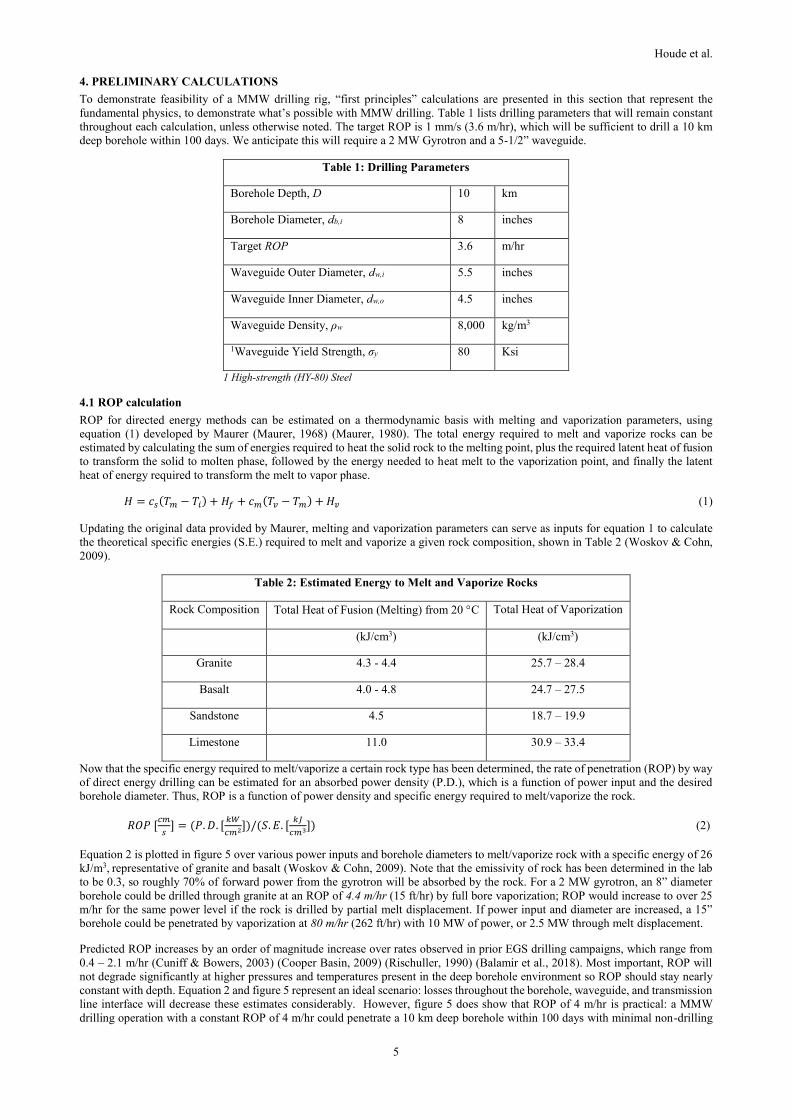
4. PRELIMINARY CALCULATIONS
To demonstrate feasibility of a MMW drilling rig, “first principles” calculations are presented in this section that represent the
fundamental physics, to demonstrate what’s possible with MMW drilling. Table 1 lists drilling parameters that will remain constant
throughout each calculation, unless otherwise noted. The target ROP is 1 mm/s (3.6 m/hr), which will be sufficient to drill a 10 km
deep borehole within 100 days. We anticipate this will require a 2 MW Gyrotron and a 5-1/2” waveguide.
Table 1: Drilling Parameters
Borehole Depth, D 10 km
Borehole Diameter, db,i 8 inches
Target ROP 3.6 m/hr
Waveguide Outer Diameter, dw,i 5.5 inches
Waveguide Inner Diameter, dw,o 4.5 inches
Waveguide Density, ρw 8,000 kg/m3
1Waveguide Yield Strength, σy 80 Ksi
1 High-strength (HY-80) Steel
4.1 ROP calculation
ROP for directed energy methods can be estimated on a thermodynamic basis with melting and vaporization parameters, using
equation (1) developed by Maurer (Maurer, 1968) (Maurer, 1980). The total energy required to melt and vaporize rocks can be
estimated by calculating the sum of energies required to heat the solid rock to the melting point, plus the required latent heat of fusion
to transform the solid to molten phase, followed by the energy needed to heat melt to the vaporization point, and finally the latent
heat of energy required to transform the melt to vapor phase.
𝐻 = 𝑐𝑠(𝑇𝑚 − 𝑇𝑖) + 𝐻𝑓 + 𝑐𝑚(𝑇𝑣 − 𝑇𝑚) + 𝐻𝑣 (1)
Updating the original data provided by Maurer, melting and vaporization parameters can serve as inputs for equation 1 to calculate
the theoretical specific energies (S.E.) required to melt and vaporize a given rock composition, shown in Table 2 (Woskov & Cohn,
2009).
Table 2: Estimated Energy to Melt and Vaporize Rocks
Rock Composition Total Heat of Fusion (Melting) from 20 C Total Heat of Vaporization
(kJ/cm3) (kJ/cm3)
Granite 4.3 - 4.4 25.7 – 28.4
Basalt 4.0 - 4.8 24.7 – 27.5
Sandstone 4.5 18.7 – 19.9
Limestone 11.0 30.9 – 33.4
Now that the specific energy required to melt/vaporize a certain rock type has been determined, the rate of penetration (ROP) by way
of direct energy drilling can be estimated for an absorbed power density (P.D.), which is a function of power input and the desired
borehole diameter. Thus, ROP is a function of power density and specific energy required to melt/vaporize the rock.
𝑅𝑂𝑃 [𝑐𝑚
𝑠] = (𝑃. 𝐷. [
𝑘𝑊
𝑐𝑚2])/(𝑆. 𝐸. [𝑘𝐽
𝑐𝑚3]) (2)
Equation 2 is plotted in figure 5 over various power inputs and borehole diameters to melt/vaporize rock with a specific energy of 26
kJ/m3, representative of granite and basalt (Woskov & Cohn, 2009). Note that the emissivity of rock has been determined in the lab
to be 0.3, so roughly 70% of forward power from the gyrotron will be absorbed by the rock. For a 2 MW gyrotron, an 8” diameter
borehole could be drilled through granite at an ROP of 4.4 m/hr (15 ft/hr) by full bore vaporization; ROP would increase to over 25
m/hr for the same power level if the rock is drilled by partial melt displacement. If power input and diameter are increased, a 15”
borehole could be penetrated by vaporization at 80 m/hr (262 ft/hr) with 10 MW of power, or 2.5 MW through melt displacement.
Predicted ROP increases by an order of magnitude increase over rates observed in prior EGS drilling campaigns, which range from
0.4 – 2.1 m/hr (Cuniff & Bowers, 2003) (Cooper Basin, 2009) (Rischuller, 1990) (Balamir et al., 2018). Most important, ROP will
not degrade significantly at higher pressures and temperatures present in the deep borehole environment so ROP should stay nearly
constant with depth. Equation 2 and figure 5 represent an ideal scenario: losses throughout the borehole, waveguide, and transmission
line interface will decrease these estimates considerably. However, figure 5 does show that ROP of 4 m/hr is practical: a MMW
drilling operation with a constant ROP of 4 m/hr could penetrate a 10 km deep borehole within 100 days with minimal non-drilling

Houde et al.
6
time, which is in line with drilling schedules for O&G and geothermal wells that are much shallower. Going forward, a target ROP
of 1 mm/s (3.6 m/hr) will serve as a benchmark for later calculations.
Figure 5: Estimated ROP for MMW Drilling, as a function of power input and borehole diameter. Note: power input for
vaporization in black font, power input for partial melt displacement in red font (Woskov & Cohn 2009).
4.2 Material removal calculation
It is critical for all drilling operations that debris can be removed from the bottom of the borehole: MMW drilling assembly
accomplishes this with the purge system, which removes both rock particles and heat during the drilling process. For full bore
vaporization, the “smoke” (rock nanoparticulate) must be removed at sufficient flow velocities that exceed the terminal velocities of
each rock particle; we estimate that nanoparticulate should not exceed one micrometer in diameter, so the velocity of the injected
purge fluid must exceed 1.28 m/s to convey upward flow.
The mass flow rate of rock removal is a simple calculation. Using a baseline ROP of 3.6 m/hr, the mass flow rate can be calculated
with density of the rock (assumed at 2,500 kg/m3 for granite). Under these assumptions, the mass flow rate comes out to 300 kg/hr.
�̇�𝑟𝑜𝑐𝑘 =𝜋
4∗ 𝑑𝑏,𝑖
2 ∗ 𝑅𝑂𝑃 ∗ 𝜌𝑟𝑜𝑐𝑘 (3)
4.2.1 Removal by full bore vaporization
The purge parameters are highly sensitive to fluid properties and dimensions of the waveguide/borehole, so we performed a limit
analysis to identify minimum/maximum bounds for the purge gas flow rates and pressure drops. The gas flow rate must exceed the
mass flow rate of nanoparticle smoke to dilute rock particulate for conveyance up-hole and to remove excess heat from downhole.
This requires a multiplier, X, that is ultimately constrained by the need to remove the heat from the downhole environment to protect
downhole metal components (waveguide). We have estimated a maximum value of 26.5 would be required in the worst-case scenario.
The flow rates generated within the waveguide and the borehole annulus are calculated with equations 4 and 5.
𝑢𝑓,𝑤 =𝛸𝜌𝑟𝑑𝑏,𝑖
2 ⋅𝑅𝑂𝑃
𝜌𝑓𝑑𝑤,𝑖2 (4)
𝑢𝑓,𝑏 =𝛸𝜌𝑟𝑑𝑏,𝑖
2 ⋅𝑅𝑂𝑃
𝜌𝑓(𝑑𝑏,𝑖2 −𝑑𝑤,𝑜
2 ) (5)
Maximum flow rates are predicted to occasionally exceed 100 m/s (see table 3) under a “worst-case scenario”, but this was driven by
the need to remove excess heat from the borehole. These maximum limits are unlikely to exist in practice given that multiple
parameters are unlikely to exist at their most extreme values simultaneously, which implies that this limit analysis requires more
refinement for better accuracy. Most flow rates were bounded between 1 m/s and 100 m/s: if the multiplier was only constrained by
the need to convey rock particles up-hole then flow rates for the purge gas should not exceed 65 m/s, so flow rate can be significantly
reduced if a cooling component were included with the waveguide. For example, a relatively small flow of circulating cooling water,
delivered by a concentric tubular downhole, could significantly decrease the expected heat transfer across the waveguide.
The purge gas will experience a significant pressure drop as it flows down through the waveguide and conveyed up-hole through the
annulus with nanoparticulate smoke. These pressure drops are determined by the flow rates generated with equations 4 and 5, along
with dimensions of the borehole and waveguide. Equations 6 and 7 predict the pressure drops generated within the waveguide and
borehole annulus (Darcy-Weisbach equation for turbulent flow in a pipe).

Houde et al.
7
𝛥𝑝𝑐,𝑤 = (−1.8 log ((
𝜀𝑐𝑑𝑤,𝑖
⁄
3.7)
1.11
+6.9𝜇𝑓
𝜌𝑓𝑢𝑓,𝑤𝑑𝑤,𝑖))
−2
𝜌𝑓𝑢𝑓,𝑤2
2
𝑙𝑐
𝑑𝑤,𝑖 (6)
𝛥𝑝𝑐,𝑏 = (−1.8 log ((
𝜀𝑐(𝑑𝑏,𝑖−𝑑𝑤,𝑜)⁄
3.7)
1.11
+6.9𝜇𝑓
𝜌𝑓𝑢𝑓,𝑏(𝑑𝑏,𝑖−𝑑𝑤,𝑜)))
−2
𝜌𝑓𝑢𝑓,𝑏2
2
𝑙𝑐
𝑑𝑏,𝑖−𝑑𝑤,𝑜 (7)
In a worst-case scenario the pressure drop could exceed 100 MPa, due to the large flow rates required to remove excess heat from the
downhole system (see table 3 for purge gas limits). These pressure drops are highly impractical, as the pumping power required alone
would be prohibitively expensive and outside the limits of available pumping technology. However, these maximum limits are also
unlikely to occur in practice, and the wide range in pressure drop implies much lower pressure drops in realistic conditions.
Regardless, high flow rates and pressure drops could be required to remove excess heat from the borehole and this issue must be
addressed for full-scale operating conditions.
Table 3: Limits for Purge Gas Parameters
Parameter Nomenclature Minimum limit Maximum limit Units
Pressure Drop
(waveguide) Δpc,w 0.0007 82.50 MPa
Purge Velocity
(waveguide) uf,w 0.153 841 m/s
Pressure Drop
(borehole annulus) Δpc,b 0.0013 123 MPa
Purge Velocity
(borehole annulus) uf,b 0.09 327 m/s
4.2.2 Removal by partial melt displacement
Rock melt can be permeated into the surrounding rock, provided there is enough pressure generated downhole to “push” the rock
melt into low permeability granite. The drilling process will generate a volumetric rate of rock melt generated (equation 8), based on
ROP.
𝑞𝑚𝑒𝑙𝑡 =𝜋
4∗ 𝑑𝑏,𝑖 ∗ 𝑅𝑂𝑃 (8)
We assume half of the melt flow makes up the 1” thick vitrified wall along the 8” diameter BH, db,i = 8”; the remaining half must be
displaced into the in-situ granite for removal, or dmelt=10”;. Assuming a liner thickness of 1” (see section 4.3); liquid viscosity of 4
poise for the granite melt, υmelt; and the permeability of thermally-cracked granite, k equal to 10-14 m2; then the downhole pressure
gradient required to displace granitic melt into the surrounding formation is expressed by equation 9, which comes out to 900 MPa.
𝛥𝑝𝑚𝑒𝑙𝑡 =1
16∗ (𝜐𝑚𝑒𝑙𝑡)/(𝑘) ∗ (𝑑𝑏,𝑖)/(𝑡) ∗ 𝑅𝑂𝑃 ∗ ln (𝑑𝑚𝑒𝑙𝑡/𝑑𝑏,𝑖) (9)
900 MPa is within bounds of the overpressure condition (1000 MPa) estimated as a result of high-temperature drilling operation, but
in-situ granite will have a permeability closer to 10-18 m2, three orders of magnitude higher. We are assuming that cracking due to
thermal stresses and the overpressure will enhance permeability by nearly 4 orders of magnitude. Thermally induced microfractures
will only increase porosity by a few percent, but a small percent change in porosity could increase permeability by 7 orders of
magnitude or more (Meredith et al., 2012). Therefore, our assumption is within bounds for temporary permeability enhancement due
to thermal cracking but must be demonstrated experimentally in later testing campaigns. A more detailed analysis would incorporate
a dynamic, multi-physics (geomechanics, heat transfer, fluid mechanics) simulation of the melt displacement process to identify
proper limits for permeability enhancement and pressure gradient required to permeate melt into in-situ granite.
4.3 Liner strength calculation
The formation of a vitrified borehole liner by rock melting penetration was first demonstrated in the Los Alamos Subterrene project
(Altseimer et al., 1976). Glass melt has proven to be more competent than an unlined open borehole and should also serve as an ideal
conduit for high temperature corrosive geothermal fluids, which would damage conventional steel + cement casing (Rowley &
Neudecker, 1985). Casing could range up to 50%-70% of total well costs if a specialty alloy like titanium casing is required to mitigate
corrosion (GEECO, 2011).
The vitrified liner will require a certain thickness to prevent wellbore collapse. Glass can have a compressive strength of 1000 MPa
(Physical Properties of Glass). At 10 km depth, we can expect a lithostatic pressure of 250 MPa downhole for granite (density = 2500
kg/m3). The wellbore will experience a compressive hoop stress, and failure (borehole collapse) occurs when the borehole hoop stress
exceeds the compressive strength of the glass.
𝜎𝑐,𝑏 =𝑃𝑙𝑖𝑡ℎ∗𝑑𝑏,𝑖
2𝑡 (10)
Solving equation 10 for thickness with assuming an 8” diameter borehole, we find that the vitrified wall only needs to be 1” thick to
prevent borehole collapse, all the way down to 10 km.

Houde et al.
8
4.4 Rig structure calculation
Monobore capability will be constrained by the yield strength of the waveguide, which could fail under its own weight at km-length
pipe segments. The waveguide will fail when the axial stress (i.e. weight) exceeds the yield strength of waveguide material (steel).
𝜎𝑦,𝑤 = 𝐿 ∗ 𝜌𝑤 ∗ 𝑔 (11)
Using the waveguide parameters given in table 1 and solving equation 11 for length of waveguide, L, results in a maximum length
of 7 km before the waveguide should yield under its own weight. To exceed 7 km, waveguide segments must be suspended under a
waveguide with larger diameter up-hole, like the “telescope” geometry used in conventional casing programs.
If a 10 km long, telescoping waveguide can be fabricated, then we can determine the strength and power rating of “drilling rig”
required to support the waveguide assembly. Assuming a safety factor of 2, the weight rating can be calculated with equation 12
which comes out to 900 tons-force for the rig’s weight rating: a 1000-ton rig will be required.
𝑅 = 2 ∗ 𝑤𝑒𝑖𝑔ℎ𝑡 𝑟𝑎𝑡𝑖𝑛𝑔 =𝜋
2∗ (𝑑𝑤,𝑜
2 − 𝑑𝑤,𝑖2 ) ∗ 𝐿 ∗ 𝜌𝑤 ∗ 𝑔 (12)
The minimum power rating for the rig must support and convey the waveguide at 1 m/s when the waveguide is being raised or
lowered. Equation 13 yields a power rating of 5,300 horsepower (HP), which is large but within range of operational drilling rigs.
𝑃𝑟𝑖𝑔 (𝑝𝑜𝑤𝑒𝑟 𝑟𝑎𝑡𝑖𝑛𝑔) = 𝑤 ∗ 𝑣𝑤 =𝜋
2∗ (𝑑𝑤,𝑜
2 − 𝑑𝑤,𝑖2 ) ∗ 𝐿 ∗ 𝜌 ∗ 𝑔 ∗ 𝑣𝑤 (13)
5. COST MODEL
A techno-economic analysis for MMW drilling operation was previously conducted by MIT and Impact Technologies, using the US
Air Force 2 MW, 95 GHz gyrotron system as a reference (Oglesby et al, 2014). Estimates for capital and operational expenses are
broken down in the tables below, extrapolated to a 10 km deep, 8” diameter hole section. Capital costs include the gyrotron tube,
magnet, and Mirror Optics Unit (MOU) assembly; downhole waveguide and piping; purge injection subsystem, with compressors
and electric generator; and the MMW-specific rig structure, including the wellhead manifold as well as cooling and controls
subsystems for the gyrotron (CPI 2018). The total capital cost for the MMW drilling rig comes out to $21.3M, or $213k per well if
amortized over a 100 well lifetime for the rig. However, our approach would retrofit a conventional rig with hybrid MMW drilling
capability, so the total capital cost should also factor in the cost of a conventional drill rig, estimated at $100M-$150M (including
expenses to retrofit for MMW drilling capability). Total capital costs now equal $171.3M, so clearly the MMW components only
make up 10-20% of the total rig cost. The operational costs depend on the price of electricity, the only consumable required for
operation (purge gas will be cooled, treated, and recycled). To drill a 10 km deep well with 2 MW in 100 days requires 11,111 MWh
of electricity. Assuming $0.1/kWh for the price of electricity yields an operational cost of $1.11M. Combining capital and operational
expenses, we predict the total cost of drilling a 10 km well with MMW comes out to $2.82M, or $282.4/m. Note these are drilling-
only costs for MMW; as explained below, we will complement MMW drilling through basement rock to target depth with a
conventional drilling operation from the surface to the basement rock contact, which will raise total well costs significantly.
Table 5: Cost to drill a full-sized well (10 km, 8” diameter) MMW
Unit Cost ($ million USD) Notes
Capital Costs
2 MW Gyrotron $2.5M 2-MW tube, magnet, MOU assembly, and diamond window
Downhole piping/waveguide $3.28M Estimated ($100/ft)
MMW Rig structure $8M Includes wellhead manifold and tools; controls and heat
exchanger subsystems for gyrotron
Purge system $7.5M High-powered compressors with gas supply and generator
Conventional rig $150M Cost assumption: Drilling rate of $15,000/day * 100 days,
amortized over 100 wells. Also includes cost to retrofit rig
for compatibility with hybrid MMW operation
Total Capital Cost $171.3M
Capital Costs (per well) $1.71M Amortized over 100 wells drilled.
Operating Costs
Electricity Costs $1.11M 10 km deep well, w/ ROP = 4 m/hr and electricity cost
$0.1/kWh
Total cost (per well) $2.82M
MMW Drilling Costs $282.4/m Conventional: $1,000/m - $4,000/m

Houde et al.
9
Few wells have been drilled past 10 km, but deep EGS wells drilled to an average depth of 5 km range from $1,000/m to $4,000/m,
so MMW drilling can reduce drilling costs 10-fold (Tester et al., 2006). Savings are representative of ROP improvement; absence of
casing costs, replaced by the vitrified liner to stabilize/support the borehole; and reducing the number of casing strings. Partial melt
displacement could increase the ROP five-fold, dropping the total cost to roughly $1.9M ($190/m) per well.
MMW drilling can greatly improve the economics of supercritical EGS anywhere due to lower well costs, despite the large depths
drilled. AltaRock has developed a model to calculate the Levelized Cost of Electricity (LCOE) for supercritical EGS, based off the
techniques used in the GETEM tool but modified for supercritical temperatures (Claudohos et al., 2018). Extrapolating drilling costs
to 10-20 km depths is impractical, but the Newberry reference used in the AltaRock model serves as a useful comparison. The
Newberry site contains a shallow heat source where supercritical temperatures are encountered near 4.5 km depth. Total well costs
came out to roughly $28M per well, which included $10M in drilling-only costs and $10M in casing costs with an expensive high-
temperature alloy like titanium, which could range up to $3,000/m (Finger & Blankenship, 2010). The overall LCOE for supercritical
EGS at the Newberry site is just over $50/MWh, which can be competitive with other alternative energy sources including wind,
solar, and advanced nuclear (EIA, 2019). Now, let’s replace the shallow well with a 20 km well drilled with MMW; this represents a
conservative depth target that would reach supercritical temperatures at most locations. We assume the first 2 km are drilled
conventional ($3,500/m, with high-temperature casing included), and the next 18 km are drilled with MMW. Total well costs for the
20 km well would come out to $23M per well, which results in an LCOE of $49/MWh. The LCOE is equivalent to the Newberry
reference case, validating the case for supercritical EGS to be competitive at 10-20 km depth anywhere with MMW drilling.
Developmental risk costs would also be avoided since supercritical EGS targets can always be reached if the well is drilled to a deeper
depth, although this was not factored into the LCOE calculation.
6. DEVELOPMENT ROADMAP
A development roadmap for MMW drilling is provided in table 6, along with the Technology Readiness Level (TRL) anticipated for
each development milestone, which is measured by aspect ratio (Borehole Length : Borehole Diameter).
Table 6: Technology Development Roadmap
Deep Drilling TRL TRL 3 TRL 4 TRL 5 TRL 6 TRL 7 TRL 8
Aspect Ratio
(Length:Diameter)
1:1
10:1
100:1
1000:1
1,000:1
50,000:1
Dimensions
(depth, diameter)
5 cm x 2” 50 cm x 2” 5 m x 2” 100 m x 2” 1 km x 4” 10 km x 8”
Power input 10 kW 100 kW 100 kW 500 kW 500 kW 1 MW
Frequency (GHz) 28 95 95 50-300 50-300 50-300
Operational time 1-10 minute 10-100
minutes
10-100
minutes
1-10 days 1-10 days 100 days
Purge: Flow Rates
(m3/s)
NA 0.001-0.01
(air)
0.01-0.1 (air) 0.01-0.1
(air)
0.1-1 (gas) 0.1-1 (gas)
Pressure (MPa) NA 0.1-1 1-10 1-10 10-300 10-300
Material Removed
(m3)
NA 0.001 0.01-1 0.01-1 10-300 10-300
Waveguide
dimensions
1 m long,
1.5” diameter
1-5 m long,
1.5” diameter
5-20 m long,
1.5” diameter
10-1000 m
long,
3” diameter
10-1000 m
long,
3” diameter
1000-10000 m
long,
6“ diameter
Waveguide
Weight Rating
200 kg 200 kg 200 kg 20,000 kg 20,000 kg 1,000,000 kg
Wellhead Pressure
Isolation
NA 1 MPa 1 MPa 100 MPa 100 MPa 300 MPa
As noted earlier, previous lab experiments were limited by the power input and low frequency for effectively penetrating boreholes,
which did not breach 50 mm depth. The next steps for experimentation and field testing follow the roadmap outlined in table 6 above.
Increasing the power level and frequency to 100 kW and 95 GHz, respectively, will enable drilling a 100:1 borehole (20-m long, 2”
diameter) above ground, which will prove material removal can be achieved over extended distances and pressures isolated at the
wellhead/away from the gyrotron. Then a MW scale gyrotron and subsystems must be acquired for the next stage of development:
this stage will incorporate a prototype “MMW drilling rig” that initially can drill shallow subsurface boreholes. It is necessary that
the prototype demonstrate compatibility with a conventional drilling rig, the steps outlined above will all be accompanied by a
modelling and simulation campaign focused on modelling the multi-physics behavior of energy-rock interaction, to justify next steps
in lab and field testing.

Houde et al.
10
Once fundamentals are demonstrated at larger aspect ratios at the surface, the next steps will steadily increase power/length/diameter
drilled to approach deep boreholes. Technology developments required to enable deep drilling include a MW-scale MMW reflected
power isolator, high-pressure windows and a pressure management scheme to mitigate the higher pressures generated downhole, and
a waveguide fill transparent to MMW at supercritical conditions (high pressures) representative of the deep borehole environment. A
final product would incorporate all components into a transportable “drilling rig” that can be combined with conventional drilling
equipment for a hybrid operation. Conventional drilling will be used to breach through the upper layer of sedimentary rock and
unconsolidated sediments, until basement rock is reached. Then MMW drilling operation takes over and drills to the predicted depth
target for supercritical temperatures.
The development timeline for supercritical EGS will take several years, so MMW technology will enter into first markets unrelated
to geothermal energy. MMW technology is widely applicable to industries that incorporate rock destruction methods (tunnel boring,
mining, trenching, construction). An above-ground drilling demonstration will prove MMW technology in the field and serve as a
basis to license MMW technology, as a near-surface rock-weakening/destruction product, for non-energy related industries, so that
our team can still focus on geothermal energy while operations experiences is acquired. For subsurface drilling, the first market could
be drilling exploratory boreholes for shallow geothermal resources (conventional or low-T EGS), with a small MMW drilling rig
prototype. Once the prototype is proven at shallow depths, we will then progress development to deeper and larger boreholes until a
10 km can be demonstrated by the MMW drilling rig.
CONCLUSION
Supercritical EGS is the only renewable, dispatchable energy source that approaches the power densities required to replace fossil
fuels for a full global low-carbon energy transition. MMW drilling can enable a supercritical EGS well anywhere on the planet,
allowing geothermal to scale as a significant source of energy to the world. MMW directed energy will vastly improve deep drilling
with conventional methods: no mechanical systems in the wellbore that could wear out or break, no limit on temperature exists,
penetration rates will become marginally more difficult with depth and harder rock, and casing could be replaced by a durable vitrified
liner. MMW drilling could make the economics of a 20 km deep, supercritical EGS well competitive with any available energy
resource, which can position geothermal energy as the leading technology for reducing greenhouse gas emissions.
NOMENCLATURE
H Total Energy required to melt or vaporize rock (J)
cs Mean Heat Capacity of Solid (J/g/K)
Ti Initial Temperature (°C)
Tm Melting Temperature (°C)
Hf Latent Heat of Fusion (J/g)
cm Mean Heat Capacity of Melt (J/g/K)
Tv Vaporization Temperature for 1-3 atm (°C)
ROP Rate of Penetration (m/s)
P.D. Power Density (kw/cm3)
S.E. Specific Energy (kJ/cm3)
�̇�𝑟𝑜𝑐𝑘 Mass Flow rate (kg/hr)
𝜌𝑟𝑜𝑐𝑘 Rock Density (kg/m3)
dw,i Inner Diameter of Waveguide (inches)
dw,o Outer Diameter of Waveguide (inches)
db,i Inner Diameter of Borehole (inches)
dmelt Diameter of melt extruded into in-situ rock (inches)
X Dilution Multiplier
uf,w Flow Rate in Waveguide (m/s)
uf,b Flow Rate in Borehole Annulus (m/s)
Δpc,w Pressure drop within Waveguide (MPa)
Δpc,b Pressure drop within Borehole Annulus (MPa)
L, lc Length of Waveguide (m)
Houde et al.
11
𝜀𝑐 Surface Roughness of Waveguide, Borehole
𝜎𝑐,𝑏 Hoop stress of Borehole (MPa)
plith Lithostatic Pressure (MPa)
qmelt Volumetric flow rate of liquid melt (m3/s)
υmelt Viscosity of liquid melt, granite (Poise)
k Permeability of in-situ granite (m2)
Δpmelt Pressure gradient required to permeate granite melt through in-situ rock (MPa)
t vitrified liner thickness (inches)
𝜎𝑦,𝑤 Waveguide Yield Strength (MPa)
𝜌𝑤 Waveguide Density (kg/m3)
Prig Rig Power Rating (HP)
vw Waveguide Velocity (m/s)
REFERENCES
Altseimer, J.H. et al.: The Subterrene Rock-Melting Concept Applied to the Production of Deep Geothermal Wells, Los Alamos
National Lab (1976), LA-UR-76-1302, Q-23.
Balamir, O., Rivas, E., Rickard, W.M., Mclennan, J., Mann, M., and Moore, J.: Utah FORGE Reservoir: Drilling Results of Deep
Characterization and Monitoring Well 58-32, Proceedings, 43rd Workshop on Geothermal Reservoir Engineering, Stanford
University, Stanford, CA (2018).
Blank, M., Borchard, P., Cahalan, P., Cauffman, S., Felch, K., and Jory, H.: Development and Demonstration of a Multi-Megawatt
95 GHz Gyrotron Oscillator, 35th IEEE Conf. on Plasma Sci., Karlsruh, Germany, (2008), IEEE 978-1-4244-1930-2/08.
CPI (Communications and Power Industries, Inc.): Private Communication (2018).
Cooper Basin Project Updates, ASX Announcements, Dec 2008 – Jan 2009, Geodynamics (2009).
Cunniff, R.A., and Browers, R.L.: Final Report Enhanced Geothermal Systems Technology, Phase II, U.S. DOE, DE-FC07-
011D14203, (2003).
Dobson, P., Asanuma, H., Huenges, E., Oletto, F., Reinsch, T. and Sanjuan, B.: . Supercritical Geothermal Systems – a Review of
Past Studies and Ongoing Research Activities, Proceedings, 41st Workshop on Geothermal Reservoir Engineering,
Stanford University, Stanford, CA (2017).
DOE (U.S. Department of Energy): Geovision Harnessing the Heat Beneath our Feet, DOE, Washington, D.C., (2019), ch. 3, p. 59.
EIA (U.S. Energy Information Administration): Levelized Cost and Levelized Avoiced Cost of New Generation Resources in the
Annual Energy Outlook 2019, DOE, Washington, D.C. (2017).
EIA (U.S. Energy Information Administration): International Energy Outlook Executive Summary, DOE, Washington, D.C. (2017).
Finger, J. and Blankenship, D.: Handbook of Best Practices for Geothermal Drilling, Sandia National Laboratories, (2010), p. 28.
Friðleifsson, G.Ó., Elders, W.A., and Albertsson, A.: The concept of the Iceland Deep Drilling Project, Geothermics (2014).
Gahan, B.G.: Processing Rock, Indust. Laser Solutions, (Sep 2005), pp. 16-18.
GEECO (Gas Equipment Engineering Corporation).: Baseline System Costs for a 50MW Enhanced Geothermal System, DOE DE-
EE0002742-002, preliminary report, (March 2011).
Hagen, K.D.: Heat Transfer with Applications, Prentice-Hall, Inc., (1999) Eq. 5-10, p.171 and Appendix D, rock thermal properties
Hunten, D.M., Turco, R.P., and Toon, O.B: Smoke and Dust Particles of Meteoric Origin in the Mesosphere and Stratosphere, J. of
Atmospheric Sci., (1980) vol. 38, 1342-1357.
Jacquinot, J.: Plasma heating and current drive systems for ITER and Future Fusion Devices, 17th IEEE/NPSS Symposium Fusion
Engineering (1998), Cat. No.97CH36131, vol.1, pp. 399-404.

Houde et al.
12
Jung, R.: EGS – Goodbye or Back to the Future, Proceedings of the International Confernce for Effective and Sustainable Hydraulic
Fracturing, Brisbane, Australia, (May 2013), ch. 5, pp. 95-121
Lowry, T.S., Foris, A., Finger, J.T., Pye, S., and Blankenship, D.A.: Implications of Drilling Technology Improvements on the
Availability of Exploitable EGS Resources, Proceedings, 42nd Workshop on Geothermal Reservoir Engineering, Stanford
University, Stanford, CA, (2017).
Maurer, W.C.: Novel Drilling Techniques, Pergamon Press, London, (1968) pp. 87-91.
Maurer, W.C. : Advanced Drilling Techniques. Petroleum Publishing Co., (1980), ch. 17.
Meredith, P. G., Main, I. G., Clint, O. C. & Li, L.: On the threshold of flow in a tight natural rock. Geophysical Research Letters,
(2012), vol. 39, issue 4.
Nikolaevskiy, V. and Garagash, I.: Earth Crust Structure as a Result of Rock Fracturing at High Pressure and Temperature Conditions,
Coupled Thermo-Hydro-Mechanical Chemical Processes in Geo-Systems (2002).
Nordstrom, D.K. and Munoz, J.L.: Geochemical Thermodynamics, 2nd edition, The Blackburn Press, (1994) Ch. 1.
Nusinovich, G.S.: Introduction to the Physics of Gyrotrons, John Hopkins Studies in Applied Physics (2004).
Nusinovich, G.S., Thumm, M.A., and Petelin, M.I.: J. Infrared Milli Terahz Waves, (2014), vol. 35 pp.325-381.
Oglesby, K.D., Woskov, P.P., Einstein, H.H., and Livesay, B.: Deep Geothermal Drilling Using Millimeter Wave Technology Final
Technical Research Report. U.S. DOE Office of EERE – Geothermal Technologies Program, (2014), pp. 15-16.
Physical Properties of Glass. Saint Gobain Building Glass UK.
Rischuller, H.: Example for Advanced Drilling Technology, Oil Gas 16 (1990), no. 4, 16-20.
Rowley, J.C. and Neudecker, J.W.: In-Situ Rock Melting Applied to Lunar Base Construction and for Exploration Drilling and Coring
on the Moon. Conference: Lunar Bases and Space Activities of the 1st Century, Washington, D.C., (1984), pp. 465-477.
Tester et al.: The Future of Geothermal Energy, MIT, (2006), Fig. 1.8.
WEC (World Energy Council): World Energy Resources: Geothermal, World Energy Council 2013, (2013), 9.2.
Whitlock, R.D. and Frick, G.M.: Particle size distributions of aerosols formed by laser ablation of solids at 760 Torr, J. Mater. Res.,
(1994), vol. 9, 2868-2872.
Woskov, P.P. and Cohn, D.R. (2008). US Patent # 8,393,410 B2: Millimeter-Wave Drilling System for Gas, Oil and Geothermal
energy.
Woskov, P.P., and Cohn, D.R.: Annual Report 2009 Millimeter Wave Deep Drilling for Geothermal Energy, Natural Gas and Oil,
MIT Plasma Science and Fusion Center, Report PSFC/ RR-09-11, Cambridge, MA (2009).
Woskov, P.P., Einstein, H.H., and Oglesby, K.D.: (2014). Penetrating rock with intense millimeter-waves. 1-2. 10.1109 IRMMW-
THz 2014 (2014), 1-2.
Woskov, P.P., and Michael, P.: Millimeter-Wave Heating, Radiometry, and Calorimetry of Granite Rock to Vaporization, 2013 IEEE
MTT-S International, Seattle, WA, (June 2013), 2-7.
Woskov, P.P. and Sundaram, S.K.: Thermal Return Reflection Method for Resolving Emissivity and Temperature in Radiometric
Measurements, MIT Plasma Science and Fusion Center, Cambridge, MA (2002).
Zimmer, A.T.: The Influence of Metallurgy on the formation of aerosols, Journal of Environmental Monitoring, (2002), vol. 4,
628-632