rexroth indradrive drive controllers power sections … instructions with regard to specific dangers...
TRANSCRIPT

Rexroth IndraControl VCP 20
IndustrialHydraulics
Electric Drivesand Controls
Linear Motion and Assembly Technologies Pneumatics
ServiceAutomation
MobileHydraulics
Rexroth IndraDrive CDrive ControllersPower Sections HCS03.1
R911307049Edition 03
Project Planning Manual
About this Documentation Rexroth IndraDrive C HCS03.1
DOK-INDRV*-HCS03.1****-PR03-EN-P
Rexroth Indra Drive C
Drive Controllers
Power Sections HCS03.1
Project Planning Manual
DOK-INDRV*-HCS03.1****-PR03-EN-P
• Box: M8*-01VRS
• Document Number 120-2400-B316-03/EN
This documentation provides information on …
• how to design the control cabinet
• how to mount the drive controllers in the control cabinet
• how to install the drive system
Description ReleaseDate
Notes
DOK-INDRV*-HCS03.1****-PR01-EN 03.2004 First Edition
DOK-INDRV*-HCS03.1****-PR02-EN 02.2005 Revision
DOK-INDRV*-HCS03.1****-PR03-EN 01.2006 Revision
Bosch Rexroth AG, 2006
Copying this document, giving it to others and the use or communicationof the contents thereof without express authority, are forbidden. Offendersare liable for the payment of damages. All rights are reserved in the eventof the grant of a patent or the registration of a utility model or design(DIN 34-1).
The specified data only serve to describe the product. No statementsconcerning a certain condition or suitability for a certain application can bederived from our information. The given information does not release theuser from the obligation of own judgement and verification. It must beremembered that our products are subject to a natural process of wearand aging.
Bosch Rexroth AGBgm.-Dr.-Nebel-Str. 2 • D-97816 Lohr a. Main
Telephone +49 (0)93 52/40-0 • Tx 68 94 21 • Fax +49 (0)93 52/40-48 85
http://www.boschrexroth.com/
Dept. BRC/EDY1 (RR, US)
This document has been printed on chlorine-free bleached paper.
Title
Type of Documentation
Document Typecode
Internal File Reference
Purpose of Documentation
Copyright
Validity
Published by
Note

Rexroth IndraDrive C HCS03.1 Contents I
DOK-INDRV*-HCS03.1****-PR03-EN-P
Contents
1 Indroduction 1-1
1.1 Documentation.............................................................................................................................. 1-1
About this Documentation ....................................................................................................... 1-1
Documentations - Overview .................................................................................................... 1-2
1.2 Basic Design of a Drive Controller................................................................................................ 1-3
1.3 General Information on How to Install the Drive Controller .......................................................... 1-5
2 Important Directions for Use 2-1
2.1 Appropriate Use............................................................................................................................ 2-1
Introduction .............................................................................................................................. 2-1
Areas of Use and Application .................................................................................................. 2-2
2.2 Inappropriate Use ......................................................................................................................... 2-2
3 Safety Instructions for Electric Drives and Controls 3-1
3.1 General Information ...................................................................................................................... 3-1
Using the Safety Instructions and Passing them on to Others................................................ 3-1
Instructions for Use.................................................................................................................. 3-1
Explanation of Warning Symbols and Degrees of Hazard Seriousness ................................. 3-3
Hazards by Improper Use........................................................................................................ 3-4
3.2 Instructions with Regard to Specific Dangers............................................................................... 3-5
Protection Against Contact with Electrical Parts ..................................................................... 3-5
Protection Against Electric Shock by Protective Low Voltage (PELV) .................................... 3-6
Protection Against Dangerous Movements ............................................................................. 3-7
Protection Against Magnetic and Electromagnetic Fields During Operation andMounting .................................................................................................................................. 3-9
Protection Against Contact with Hot Parts ............................................................................ 3-10
Protection During Handling and Mounting............................................................................. 3-11
Battery Safety ........................................................................................................................ 3-11
Protection Against Pressurized Systems .............................................................................. 3-12
4 Identification 4-1
4.1 Device Types ................................................................................................................................ 4-1
Type Code ............................................................................................................................... 4-1
4.2 Type Plates ................................................................................................................................... 4-2
Type Plate Power Section (Example)...................................................................................... 4-3
Type Plate Control Section...................................................................................................... 4-3
4.3 Scope of Delivery.......................................................................................................................... 4-3
Overview.................................................................................................................................. 4-3

II Contents Rexroth IndraDrive C HCS03.1
DOK-INDRV*-HCS03.1****-PR03-EN-P
5 Mechanical Data 5-1
5.1 Dimensions ................................................................................................................................... 5-1
Drive Controller HCS03.1E-W0070......................................................................................... 5-1
Drive Controller HCS03.1E-W0070 with HAS02 ..................................................................... 5-1
Drive Controller HCS03.1E-W0100, -W0150 .......................................................................... 5-2
Drive Controller HCS03.1E-W0100, -W0150 with HAS02 ...................................................... 5-2
Drive Controller HCS03.1E-W0210......................................................................................... 5-3
Drive Controller HCS03.1E-W0210 with HAS02 ..................................................................... 5-3
5.2 Weight........................................................................................................................................... 5-6
Mounting Position .................................................................................................................... 5-7
Temperatures Above the Top of the Device............................................................................ 5-7
6 Electrical Data 6-1
6.1 Power Section - Mains Supply...................................................................................................... 6-1
6.2 Power Section - DC Bus ............................................................................................................... 6-1
6.3 Power Section - DC Bus Power.................................................................................................... 6-2
Mains Connection Power and DC Bus Continuous Power ..................................................... 6-3
6.4 Power Section - Braking Resistor................................................................................................. 6-6
6.5 Power Section - Inverter ............................................................................................................... 6-7
6.6 Power Section - Examples of Allowed Output Current Profiles.................................................... 6-8
6.7 Power Section - Operating Standard Motors.............................................................................. 6-10
6.8 Power Section - Cooling, Power Dissipation, Insulation Resistance, Sound Pressure.............. 6-11
6.9 Control Voltage ........................................................................................................................... 6-12
Devices with Control Voltage Generation from DC Bus (HCS03.1E-W0xxx-NNxV)............. 6-12
6.10 Connections................................................................................................................................ 6-14
Overall Connection Diagram ................................................................................................. 6-14
6.11 Connections at Power Section HCS03.1.................................................................................... 6-15
Optional Control Voltage ....................................................................................................... 6-18
DC Bus .................................................................................................................................. 6-18
X1, Module Bus ..................................................................................................................... 6-19
X3, Mains Connection ........................................................................................................... 6-20
X5, Motor Connection............................................................................................................ 6-21
X6, Motor Temperature Monitoring and Motor Holding Brake .............................................. 6-23
X9, Braking Resistor.............................................................................................................. 6-26
XS1, Shield Connection......................................................................................................... 6-27
Ground Connection of Housing ............................................................................................. 6-27
Connection Point of Equipment Grounding Conductor ......................................................... 6-28
7 Touch Guard 7-1
Cutouts .................................................................................................................................... 7-1
Mounting .................................................................................................................................. 7-2
8 Replacing Devices 8-1
8.1 General Information ...................................................................................................................... 8-1
8.2 How to Proceed When Replacing Devices................................................................................... 8-1
Replacing the Drive Controller................................................................................................. 8-1

Rexroth IndraDrive C HCS03.1 Contents III
DOK-INDRV*-HCS03.1****-PR03-EN-P
Replacing the Motor ................................................................................................................ 8-2
Replacing Cables .................................................................................................................... 8-3
8.3 Fault Report .................................................................................................................................. 8-4
9 Disposal and Environmental Protection 9-1
9.1 Disposal ........................................................................................................................................ 9-1
Products................................................................................................................................... 9-1
Packaging Materials ................................................................................................................ 9-1
9.2 Environmental Protection.............................................................................................................. 9-1
No Release of Hazardous Substances ................................................................................... 9-1
Materials Contained in the Products ....................................................................................... 9-1
Recycling ................................................................................................................................. 9-1
10 Service & Support 10-1
10.1 Helpdesk..................................................................................................................................... 10-1
10.2 Service-Hotline ........................................................................................................................... 10-1
10.3 Internet........................................................................................................................................ 10-1
10.4 Vor der Kontaktaufnahme... - Before contacting us... ................................................................ 10-1
10.5 Kundenbetreuungsstellen - Sales & Service Facilities ............................................................... 10-2
11 Index 11-1

IV Contents Rexroth IndraDrive C HCS03.1
DOK-INDRV*-HCS03.1****-PR03-EN-P

Rexroth IndraDrive C HCS03.1 Indroduction 1-1
DOK-INDRV*-HCS03.1****-PR03-EN-P
1 Indroduction
1.1 Documentation
About this DocumentationThis documentation basically contains the technical data of the RexrothIndraDrive C HCS03.1 drive controllers.
WARNING
Personal injury and property damage caused byincorrect project planning for applications,machines and installations!⇒ Take the content of the Project Planning Manual
"Rexroth IndraDrive Drive System" (DOK-INDRV*-SYSTEM*****-PRxx-EN-P; part no. R911309636)into account.
For complete project planning of a Rexroth IndraDrive drive system youneed, in any case, the Project Planning Manual "Rexroth IndraDrive DriveSystem" (DOK-INDRV*-SYSTEM*****-PRxx-EN-P; part no. R911309636).This Project Planning Manual, among other things, contains:
• specifications for the components of the drive system
• configuration of the drive system components
• arrangement of the components in the control cabinet
• electromagnetic compatibility (EMC)
• types of mains connection
• requirements to the mains connection
• control circuits for the mains connection
• connections of the components in the drive system
• fusing and selecting the mains contactor
• accessories in the drive system
• calculations (determining appropriate drive controller; mainsconnection; leakage capacitance; operating data of mains filters;selecting the 24V supply; braking behavior when using a DC busresistor unit)
• notes on how to replace devices

1-2 Indroduction Rexroth IndraDrive C HCS03.1
DOK-INDRV*-HCS03.1****-PR03-EN-P
Documentations - OverviewFor project planning of the drive system the following documentations areavailable:
Title Kind of documentation Document typecode1)
Rexroth IndraDriveDrive System
Project Planning Manual DOK-INDRV*-SYSTEM*****-PRxx-EN-P
Rexroth IndraDriveDrive ControllersControl Sections CSx
Project Planning Manual DOK-INDRV*-CSH********-PRxx-EN-P
Rexroth IndraDrive MDrive ControllersPower Sections HMx
Project Planning Manual DOK-INDRV*-HMS+HMD****-PRxx-EN-P
Rexroth IndraDrive CDrive ControllersPower Sections HCS02.1
Project Planning Manual DOK-INDRV*-HCS02.1****-PRxx-EN-P
Rexroth IndraDrive CDrive ControllersPower Sections HCS03.1
Project Planning Manual DOK-INDRV*-HCS03.1****-PRxx-EN-P
Rexroth IndraDriveSupply Units
Project Planning Manual DOK-INDRV*-HMV-*******-PRxx-EN-P
Rexroth IndraDriveAdditional Components
Project Planning Manual DOK-INDRV*-ADDCOMP****-PRxx-EN-P
Rexroth IndraDriveIntegrated Safety Technology
Functional and ApplicationDescription
DOK-INDRV*-SI*-**VRS**-FKxx-EN-P
Rexroth IndraDriveFirmware for Drive Controllers
Functional Description DOK-INDRV*-MP*-02VRS**-FKxx-EN-P
Rexroth IndraDriveFirmware for Drive Controllers
Functional Description DOK-INDRV*-MP*-03VRS**-FKxx-EN-P
Rexroth IndraDriveFirmware for Drive Controllers
Functional Description DOK-INDRV*-MP*-04VRS**-FKxx-EN-P
Rexroth IndraDriveFirmware for Drive Controllers
Parameter Description DOK-INDRV*-GEN-**VRS**-PAxx-EN-P
Rexroth IndraDriveFirmware for Drive Controllers
Troubleshooting Guide DOK-INDRV*-GEN-**VRS**-WAxx-EN-P
Rexroth Connection Cables Selection Data DOK-CONNEC-CABLE*STAND-AUxx-EN-P
Rexroth IndraDyn AAsynchronous Motors MAD/MAF
Project Planning Manual DOK-MOTOR*-MAD/MAF****-PRxx-EN-P
Rexroth IndraDyn SSynchronous Motors MSK
Project Planning Manual DOK-MOTOR*-MSK********-PRxx-EN-P
Rexroth IndraDyn TSynchronous Torque Motors MBT
Project Planning Manual DOK-MOTOR*-MBT********-PRxx-EN-P
Rexroth IndraDyn HSynchronous Kit –Spindle MotorsMBS-H
Project Planning Manual DOK-MOTOR*-MBS-H******-PRxx-EN-P
Rexroth IndraDyn LSynchronous Linear Motors MLF
Project Planning Manual DOK-MOTOR*-MLF********-PRxx-EN-P
Safety Instructions for Electrical Drives Safety Guidelines DOK-GENERAL-DRIVE******-SVSx-MS-P
1) In the document typecodes "xx" is a wild card for the current editionof the documentation (example: "PR01" is the first edition of aProject Planning Manual)
Fig. 1-1: Documentations - overview

Rexroth IndraDrive C HCS03.1 Indroduction 1-3
DOK-INDRV*-HCS03.1****-PR03-EN-P
1.2 Basic Design of a Drive Controller
�
�
1: Power section2: Control section
Fig. 1-2: Basic design
The drive controller consists of two essential parts:
• Power section
• Control section

1-4 Indroduction Rexroth IndraDrive C HCS03.1
DOK-INDRV*-HCS03.1****-PR03-EN-P
Power SectionThe following are connected to the power section:
• mains voltage
• motor
• 24 V power supply (optional)
• module bus (for cross communication in the case of DC busconnection with other devices)
• motor holding brake (optional)
• motor temperature sensor (optional)
• braking resistor (optional)
Control SectionThe control section is a separate component that is plugged into thepower section. The drive controller is supplied ex works complete withcontrol section.
The control section may only be replaced by qualified personnel.
The contacts X31/1 and X31/2 are connected to the control section as Bbcontacts.
Note: The control sections are described in a separatedocumentation (see page 1-2).

Rexroth IndraDrive C HCS03.1 Indroduction 1-5
DOK-INDRV*-HCS03.1****-PR03-EN-P
1.3 General Information on How to Install the Drive Controller
Damage can be caused to the drive controller or circuit boards ifelectrostatic charging present in people and/or tools is discharged acrossthem. Therefore, please note the following information:
CAUTION
Electrostatic charges can cause damage toelectronic components and interfere with theiroperational safety!Exposed conductive parts coming into contact with
components and circuit boards must be discharged bymeans of grounding. Otherwise errors may occurwhen triggering motors and moving elements.
Such exposed conductive parts include:
• the copper bit when soldering
• the human body (ground connection caused by touching a conductive,grounded item)
• parts and tools (place them on a conductive support)
Endangered components may only be stored or dispatched in conductivepackaging.
Note: Rexroth connection diagrams are only to be used forproducing installation connection diagrams! The machinemanufacturer’s installation connection diagrams must be usedfor wiring the installation!
• Lay signal lines separately from the load resistance lines because ofthe occurrence of interference.
• Transmit analog signals (e.g. command values, actual values) viashielded lines.
• Do not connect mains, DC bus or power leads to low voltages or allowthem to come into contact with these.
• When carrying out a high voltage test or an applied-overvoltagewithstand test on the machine’s electrical equipment, disconnect allconnections to the devices. This protects the electronic components(allowed in accordance with EN 60204-1). During their routine testing,Rexroth drive components are tested for high voltage and insulation inaccordance with EN 50178.
CAUTION
Risk of damage to the drive controller byconnecting and disconnecting live connections!⇒ Do not connect and disconnect live connections.

1-6 Indroduction Rexroth IndraDrive C HCS03.1
DOK-INDRV*-HCS03.1****-PR03-EN-P

Rexroth IndraDrive C HCS03.1 Important Directions for Use 2-1
DOK-INDRV*-HCS03.1****-PR03-EN-P
2 Important Directions for Use
2.1 Appropriate Use
IntroductionRexroth products represent state-of-the-art developments andmanufacturing. They are tested prior to delivery to ensure operating safetyand reliability.
The products may only be used in the manner that is defined asappropriate. If they are used in an inappropriate manner, then situationscan develop that may lead to property damage or injury to personnel.
Note: Rexroth as manufacturer is not liable for any damagesresulting from inappropriate use. In such cases, the guaranteeand the right to payment of damages resulting frominappropriate use are forfeited. The user alone carries allresponsibility of the risks.
Before using Rexroth products, make sure that all the pre-requisites foran appropriate use of the products are satisfied:
• Personnel that in any way, shape or form uses our products must firstread and understand the relevant safety instructions and be familiarwith appropriate use.
• If the products take the form of hardware, then they must remain intheir original state, in other words, no structural changes are permitted.It is not permitted to decompile software products or alter sourcecodes.
• Do not mount damaged or faulty products or use them in operation.
• Make sure that the products have been installed in the mannerdescribed in the relevant documentation.

2-2 Important Directions for Use Rexroth IndraDrive C HCS03.1
DOK-INDRV*-HCS03.1****-PR03-EN-P
Areas of Use and ApplicationDrive controllers made by Bosch Rexroth are designed to controlelectrical motors and monitor their operation.
Control and monitoring of the motors may require additional sensors andactors.
Note: The drive controllers may only be used with the accessoriesand parts specified in this document. If a component has notbeen specifically named, then it may not be either mounted orconnected. The same applies to cables and lines.
Operation is only permitted in the specified configurations andcombinations of components using the software and firmwareas specified in the relevant Functional Descriptions.
Every drive controller has to be programmed before commissioning,making it possible for the motor to execute the specific functions of anapplication.
The drive controllers have been developed for use in single- and multi-axis drive and control tasks.
To ensure an application-specific use, the drive controllers are availablewith different drive power and different interfaces.
Typical applications of the drive controllers include:
• handling and mounting systems,
• packaging and food machines,
• printing and paper processing machines and
• machine tools.
The drive controllers may only be operated under the assembly andinstallation conditions described in this documentation, in the specifiedposition of normal use and under the ambient conditions as described(temperature, degree of protection, humidity, EMC, etc.).
2.2 Inappropriate Use
Using the drive controllers outside of the operating conditions described inthis documentation and outside of the indicated technical data andspecifications is defined as "inappropriate use".
Drive controllers must not be used, if…
• …they are subject to operating conditions that do not meet thespecified ambient conditions. This includes, for example, operationunder water, under extreme temperature fluctuations or extremely highmaximum temperatures.
• Furthermore, the drive controllers must not be used in applicationswhich have not been expressly authorized by Rexroth.
• Please carefully follow the specifications outlined in the general SafetyInstructions!

Rexroth IndraDrive C HCS03.1 Safety Instructions for Electric Drives and Controls 3-1
DOK-INDRV*-HCS03.1****-PR03-EN-P
3 Safety Instructions for Electric Drives and Controls
3.1 General Information
Using the Safety Instructions and Passing them on to OthersDo not attempt to install or commission this device without first reading alldocumentation provided with the product. Read and understand thesesafety instructions and all user documentation prior to working with thedevice. If you do not have the user documentation for the device, contactyour responsible Bosch Rexroth sales representative. Ask for thesedocuments to be sent immediately to the person or persons responsiblefor the safe operation of the device.
If the device is resold, rented and/or passed on to others in any otherform, then these safety instructions must be delivered with the device.
WARNING
Improper use of these devices, failure to followthe safety instructions in this document ortampering with the product, including disablingof safety devices, may result in materialdamage, bodily harm, electric shock or evendeath!
Instructions for UseRead these instructions before the initial startup of the equipment in orderto eliminate the risk of bodily harm or material damage. Follow thesesafety instructions at all times.
• Bosch Rexroth AG is not liable for damages resulting from failure toobserve the warnings provided in this documentation.
• Read the operating, maintenance and safety instructions in yourlanguage before starting up the machine. If you find that you cannotcompletely understand the documentation for your product, pleaseask your supplier to clarify.
• Proper and correct transport, storage, assembly and installation aswell as care in operation and maintenance are prerequisites foroptimal and safe operation of this device.
• Only assign trained and qualified persons to work with electricalinstallations:
• Only persons who are trained and qualified for the use andoperation of the device may work on this device or within itsproximity. The persons are qualified if they have sufficientknowledge of the assembly, installation and operation of theequipment as well as an understanding of all warnings andprecautionary measures noted in these instructions.
• Furthermore, they must be trained, instructed and qualified toswitch electrical circuits and devices on and off in accordance withtechnical safety regulations, to ground them and to mark themaccording to the requirements of safe work practices. They musthave adequate safety equipment and be trained in first aid.
• Only use spare parts and accessories approved by the manufacturer.
• Follow all safety regulations and requirements for the specificapplication as practiced in the country of use.

3-2 Safety Instructions for Electric Drives and Controls Rexroth IndraDrive C HCS03.1
DOK-INDRV*-HCS03.1****-PR03-EN-P
• The devices have been designed for installation in industrialmachinery.
• The ambient conditions given in the product documentation must beobserved.
• Only use safety-relevant applications that are clearly and explicitlyapproved in the Project Planning Manual. If this is not the case, theyare excluded.Safety-relevant are all such applications which can cause danger topersons and material damage.
• The information given in the documentation of the product with regardto the use of the delivered components contains only examples ofapplications and suggestions.
The machine and installation manufacturer must
• make sure that the delivered components are suited for hisindividual application and check the information given in thisdocumentation with regard to the use of the components,
• make sure that his application complies with the applicablesafety regulations and standards and carry out the requiredmeasures, modifications and complements.
• Startup of the delivered components is only permitted once it is surethat the machine or installation in which they are installed complieswith the national regulations, safety specifications and standards ofthe application.
• Operation is only permitted if the national EMC regulations for theapplication are met.
• The instructions for installation in accordance with EMC requirementscan be found in the documentation "EMC in Drive and ControlSystems".
• The machine or installation manufacturer is responsible forcompliance with the limiting values as prescribed in the nationalregulations.
• Technical data, connections and operational conditions are specifiedin the product documentation and must be followed at all times.

Rexroth IndraDrive C HCS03.1 Safety Instructions for Electric Drives and Controls 3-3
DOK-INDRV*-HCS03.1****-PR03-EN-P
Explanation of Warning Symbols and Degrees of Hazard SeriousnessThe safety instructions describe the following degrees of hazardseriousness. The degree of hazard seriousness informs about theconsequences resulting from non-compliance with the safety instructions:
Warning symbol with signalword
Degree of hazard seriousness accordingto ANSI Z 535
DANGER
Death or severe bodily harm will occur.
WARNING
Death or severe bodily harm may occur.
CAUTION
Bodily harm or material damage may occur.
Fig. 3-1: Hazard classification (according to ANSI Z 535)

3-4 Safety Instructions for Electric Drives and Controls Rexroth IndraDrive C HCS03.1
DOK-INDRV*-HCS03.1****-PR03-EN-P
Hazards by Improper Use
DANGER
High electric voltage and high working current!Risk of death or severe bodily injury by electricshock!
DANGER
Dangerous movements! Danger to life, severebodily harm or material damage byunintentional motor movements!
WARNING
High electric voltage because of incorrectconnection! Risk of death or bodily injury byelectric shock!
WARNING
Health hazard for persons with heartpacemakers, metal implants and hearing aids inproximity to electrical equipment!
CAUTION
Hot surfaces on device housing! Danger ofinjury! Danger of burns!
CAUTION
Risk of injury by improper handling! Risk ofbodily injury by bruising, shearing, cutting,hitting, or improper handling of pressurizedlines!
CAUTION
Risk of injury by improper handling of batteries!

Rexroth IndraDrive C HCS03.1 Safety Instructions for Electric Drives and Controls 3-5
DOK-INDRV*-HCS03.1****-PR03-EN-P
3.2 Instructions with Regard to Specific Dangers
Protection Against Contact with Electrical Parts
Note: This section only concerns devices and drive components withvoltages of more than 50 Volt.
Contact with parts conducting voltages above 50 Volts can causepersonal danger and electric shock. When operating electrical equipment,it is unavoidable that some parts of the devices conduct dangerousvoltage.
DANGER
High electrical voltage! Danger to life, electricshock and severe bodily injury!⇒ Only those trained and qualified to work with or on
electrical equipment are permitted to operate,maintain and repair this equipment.
⇒ Follow general construction and safety regulationswhen working on electrical power installations.
⇒ Before switching on the device, the equipmentgrounding conductor must have been non-detachably connected to all electrical equipment inaccordance with the connection diagram.
⇒ Do not operate electrical equipment at any time,even for brief measurements or tests, if theequipment grounding conductor is not permanentlyconnected to the mounting points of the componentsprovided for this purpose.
⇒ Before working with electrical parts with voltagepotentials higher than 50 V, the device must bedisconnected from the mains voltage or powersupply unit. Provide a safeguard to preventreconnection.
⇒ With electrical drive and filter components, observethe following:Wait 30 minutes after switching off power to allowcapacitors to discharge before beginning to work.Measure the voltage on the capacitors beforebeginning to work to make sure that the equipment issafe to touch.
⇒ Never touch the electrical connection points of acomponent while power is turned on.
⇒ Install the covers and guards provided with theequipment properly before switching the device on.Before switching the equipment on, cover andsafeguard live parts safely to prevent contact withthose parts.
⇒ A residual-current-operated circuit-breaker or r.c.d.cannot be used for electric drives! Indirect contactmust be prevented by other means, for example, byan overcurrent protective device according to therelevant standards.
⇒ Secure built-in devices from direct touching ofelectrical parts by providing an external housing, forexample a control cabinet.
European countries: according to EN 50178/ 1998,

3-6 Safety Instructions for Electric Drives and Controls Rexroth IndraDrive C HCS03.1
DOK-INDRV*-HCS03.1****-PR03-EN-P
section 5.3.2.3.
USA: See National Electrical Code (NEC), NationalElectrical Manufacturers' Association (NEMA), as well aslocal engineering regulations. The operator must observeall the above regulations at any time.
With electrical drive and filter components, observe the following:
DANGER
High housing voltage and large leakage current!Risk of death or bodily injury by electric shock!⇒ Before switching on, the housings of all electrical
equipment and motors must be connected orgrounded with the equipment grounding conductor tothe grounding points. This is also applicable beforeshort tests.
⇒ The equipment grounding conductor of the electricalequipment and the units must be non-detachablyand permanently connected to the power supply unitat all times. The leakage current is greater than3.5 mA.
⇒ Over the total length, use copper wire of a crosssection of a minimum of 10 mm2 for this equipmentgrounding connection!
⇒ Before start-up, also in trial runs, always attach theequipment grounding conductor or connect with theground wire. Otherwise, high voltages may occur atthe housing causing electric shock.
Protection Against Electric Shock by Protective Low Voltage (PELV)All connections and terminals with voltages between 5 and 50 Volt atRexroth products are protective extra-low voltage systems which areprovided with touch guard according to the product standards.
WARNING
High electric voltage by incorrect connection!Risk of death or bodily injury by electric shock!⇒ To all connections and terminals with voltages
between 0 and 50 Volt, only devices, electricalcomponents, and conductors may be connectedwhich are equipped with a PELV (Protective Extra-Low Voltage) system.
⇒ Connect only voltages and circuits which are safelyisolated from dangerous voltages. Safe isolation isachieved for example by isolating transformers, safeoptocouplers or battery operation without mainsconnection.

Rexroth IndraDrive C HCS03.1 Safety Instructions for Electric Drives and Controls 3-7
DOK-INDRV*-HCS03.1****-PR03-EN-P
Protection Against Dangerous MovementsDangerous movements can be caused by faulty control of connectedmotors. Some common examples are:
• improper or wrong wiring of cable connections
• incorrect operation of the equipment components
• wrong input of parameters before operation
• malfunction of sensors, encoders and monitoring devices
• defective components
• software or firmware errors
Dangerous movements can occur immediately after equipment isswitched on or even after an unspecified time of trouble-free operation.
The monitoring in the drive components will normally be sufficient to avoidfaulty operation in the connected drives. Regarding personal safety,especially the danger of bodily harm and material damage, this alonecannot be relied upon to ensure complete safety. Until the integratedmonitoring functions become effective, it must be assumed in any casethat faulty drive movements will occur. The extent of faulty drivemovements depends upon the type of control and the state of operation.

3-8 Safety Instructions for Electric Drives and Controls Rexroth IndraDrive C HCS03.1
DOK-INDRV*-HCS03.1****-PR03-EN-P
DANGER
Dangerous movements! Danger to life, risk ofinjury, severe bodily harm or material damage!⇒ For the above reasons, ensure personal safety by
means of qualified and tested higher-level monitoringdevices or measures integrated in the installation.They have to be provided for by the user accordingto the specific conditions within the installation and ahazard and fault analysis. The safety regulationsapplicable for the installation have to be taken intoconsideration. Unintended machine motion or othermalfunction is possible if safety devices are disabled,bypassed or not activated.
To avoid accidents, bodily harm and/or materialdamage:
⇒ Keep free and clear of the machine’s range ofmotion and moving parts. Possible measures toprevent people from accidentally entering themachine’s range of motion:- use safety fences
- use safety guards
- use protective coverings
- install light curtains or light barriers
⇒ Fences and coverings must be strong enough toresist maximum possible momentum.
⇒ Mount the emergency stop switch in the immediatereach of the operator. Verify that the emergency stopworks before startup. Don’t operate the device if theemergency stop is not working.
⇒ Isolate the drive power connection by means of anemergency stop circuit or use a safety relatedstarting lockout to prevent unintentional start.
⇒ Make sure that the drives are brought to a safestandstill before accessing or entering the dangerzone.
⇒ Additionally secure vertical axes against falling ordropping after switching off the motor power by, forexample:- mechanically securing the vertical axes,
- adding an external braking/ arrester/ clampingmechanism or
- ensuring sufficient equilibration of the verticalaxes.
The standard equipment motor brake or an externalbrake controlled directly by the drive controller arenot sufficient to guarantee personal safety!

Rexroth IndraDrive C HCS03.1 Safety Instructions for Electric Drives and Controls 3-9
DOK-INDRV*-HCS03.1****-PR03-EN-P
⇒ Disconnect electrical power to the equipment using amaster switch and secure the switch againstreconnection for:- maintenance and repair work
- cleaning of equipment
- long periods of discontinued equipment use
⇒ Prevent the operation of high-frequency, remotecontrol and radio equipment near electronics circuitsand supply leads. If the use of such devices cannotbe avoided, verify the system and the installation forpossible malfunctions in all possible positions ofnormal use before initial startup. If necessary,perform a special electromagnetic compatibility(EMC) test on the installation.
Protection Against Magnetic and Electromagnetic Fields DuringOperation and Mounting
Magnetic and electromagnetic fields generated by current-carryingconductors and permanent magnets in motors represent a seriouspersonal danger to those with heart pacemakers, metal implants andhearing aids.
WARNING
Health hazard for persons with heartpacemakers, metal implants and hearing aids inproximity to electrical equipment!⇒ Persons with heart pacemakers and metal implants
are not permitted to enter following areas:- Areas in which electrical equipment and parts are
mounted, being operated or commissioned.
- Areas in which parts of motors with permanentmagnets are being stored, repaired or mounted.
⇒ If it is necessary for somebody with a pacemaker toenter such an area, a doctor must be consulted priorto doing so. The interference immunity of present orfuture implanted heart pacemakers differs greatly, sothat no general rules can be given.
⇒ Those with metal implants or metal pieces, as wellas with hearing aids must consult a doctor beforethey enter the areas described above. Otherwisehealth hazards may occur.

3-10 Safety Instructions for Electric Drives and Controls Rexroth IndraDrive C HCS03.1
DOK-INDRV*-HCS03.1****-PR03-EN-P
Protection Against Contact with Hot Parts
CAUTION
Hot surfaces at motor housings, on drivecontrollers or chokes! Danger of injury! Dangerof burns!⇒ Do not touch surfaces of device housings and
chokes in the proximity of heat sources! Danger ofburns!
⇒ Do not touch housing surfaces of motors! Danger ofburns!
⇒ According to operating conditions, temperatures canbe higher than 60 °C, 140 °F during or afteroperation.
⇒ Before accessing motors after having switched themoff, let them cool down for a sufficiently long time.Cooling down can require up to 140 minutes!Roughly estimated, the time required for coolingdown is five times the thermal time constantspecified in the Technical Data.
⇒ After switching drive controllers or chokes off, wait15 minutes to allow them to cool down beforetouching them.
⇒ Wear safety gloves or do not work at hot surfaces.⇒ For certain applications, the manufacturer of the end
product, machine or installation, according to therespective safety regulations, has to take measuresto avoid injuries caused by burns in the endapplication. These measures can be, for example:warnings, guards (shielding or barrier), technicaldocumentation.
Rexroth IndraDrive C HCS03.1 Safety Instructions for Electric Drives and Controls 3-11
DOK-INDRV*-HCS03.1****-PR03-EN-P
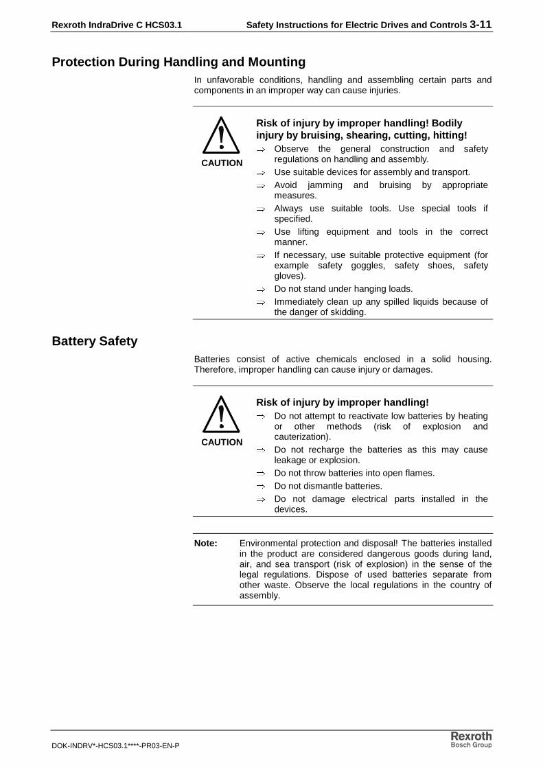
Protection During Handling and MountingIn unfavorable conditions, handling and assembling certain parts andcomponents in an improper way can cause injuries.
CAUTION
Risk of injury by improper handling! Bodilyinjury by bruising, shearing, cutting, hitting!⇒ Observe the general construction and safety
regulations on handling and assembly.⇒ Use suitable devices for assembly and transport.⇒ Avoid jamming and bruising by appropriate
measures.⇒ Always use suitable tools. Use special tools if
specified.⇒ Use lifting equipment and tools in the correct
manner.⇒ If necessary, use suitable protective equipment (for
example safety goggles, safety shoes, safetygloves).
⇒ Do not stand under hanging loads.⇒ Immediately clean up any spilled liquids because of
the danger of skidding.
Battery SafetyBatteries consist of active chemicals enclosed in a solid housing.Therefore, improper handling can cause injury or damages.
CAUTION
Risk of injury by improper handling!⇒ Do not attempt to reactivate low batteries by heating
or other methods (risk of explosion andcauterization).
⇒ Do not recharge the batteries as this may causeleakage or explosion.
⇒ Do not throw batteries into open flames.⇒ Do not dismantle batteries.⇒ Do not damage electrical parts installed in the
devices.
Note: Environmental protection and disposal! The batteries installedin the product are considered dangerous goods during land,air, and sea transport (risk of explosion) in the sense of thelegal regulations. Dispose of used batteries separate fromother waste. Observe the local regulations in the country ofassembly.

3-12 Safety Instructions for Electric Drives and Controls Rexroth IndraDrive C HCS03.1
DOK-INDRV*-HCS03.1****-PR03-EN-P
Protection Against Pressurized SystemsAccording to the information given in the Project Planning Manuals,motors cooled with liquid and compressed air, as well as drive controllers,can be partially supplied with externally fed, pressurized media, such ascompressed air, hydraulics oil, cooling liquids, and cooling lubricatingagents. In these cases, improper handling of external supply systems,supply lines, or connections can cause injuries or damages.
CAUTION
Risk of injury by improper handling of pressurizedlines!⇒ Do not attempt to disconnect, open, or cut
pressurized lines (risk of explosion).⇒ Observe the respective manufacturer's operating
instructions.⇒ Before dismounting lines, relieve pressure and
empty medium.⇒ Use suitable protective equipment (for example
safety goggles, safety shoes, safety gloves).⇒ Immediately clean up any spilled liquids from the
floor.
Note: Environmental protection and disposal! The agents used tooperate the product might not be economically friendly.Dispose of ecologically harmful agents separate from otherwaste. Observe the local regulations in the country ofassembly.
Rexroth IndraDrive C HCS03.1 Identification 4-1
DOK-INDRV*-HCS03.1****-PR03-EN-P
4 Identification
4.1 Device Types
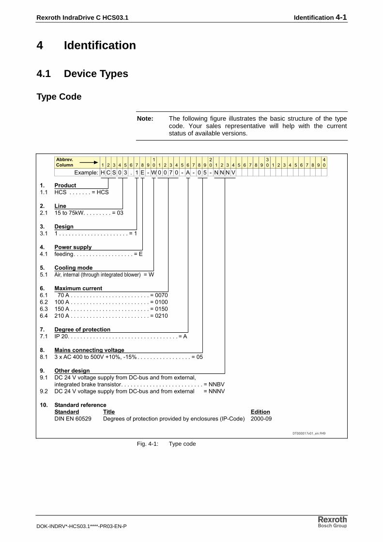
Type Code
Note: The following figure illustrates the basic structure of the typecode. Your sales representative will help with the currentstatus of available versions.
���������������
�� ��������� ��� ������������� �����
� �� ���� ����� ������������������ ����
�� ����� ��� � ������������������������������������������� ���
�� ��������������� �������������������������������������������� ���
�� ����� �������� ����������������� ������������!��"��# ���
�� ������������� $�� ������ ������������������������������������������������� ������$�� ����� ������������������������������������������������� ������$�� ���� ������������������������������������������������� �����$�� ����� ������������������������������������������������� ������
� ��������!�������� ��� %&������������������������������������������������������������������������ ���
"� ��� ���� ��� ��#�����'�� ��(������������)�*��+��,�+��������������������������������� ���
$� %&�������� -�� .�����)�/������0 11�2����3�.�,! 0��������3��(������
���������!�� �����0�0����������������������������������������������������� ��445)-�� .�����)�/������0 11�2����3�.�,! 0��������3��(����� ��444)
�'� (� �������!��� ��(� ���� )��� *���� .%4��4�$��- .�����0����1���6����1��/�����!2���6��0 ��0��%&,����# ����,�-
� � � � $ � ' -�� � � � � $ � ' -
�� � � � � $ � ' -
�� � � � � $ � ' -
��
�(�31��7
+,,��#������
� � � � � � � � , � � � � � , � , � , 4 4 4 )
Fig. 4-1: Type code

4-2 Identification Rexroth IndraDrive C HCS03.1
DOK-INDRV*-HCS03.1****-PR03-EN-P
4.2 Type Plates
Each drive component is marked by a type designation.
There is a type plate attached to all devices.
A label (cable mark) is wrapped around ready-made cables. This labelindicates the type designation and the length. (The designation of thecable itself - without connector - is printed on the cable sheath.)
The identification of accessories packed in bags is either printed on thebag or indicated in an accompanying note.
Type Plate Arrangement
�
�
1: Power section type plate2: Control section type plateFig. 4-2: Type plate arrangement

Rexroth IndraDrive C HCS03.1 Identification 4-3
DOK-INDRV*-HCS03.1****-PR03-EN-P
Type Plate Power Section (Example)
(-.�/�('�0''��
��������,�����,�,��,44441$��$"� � 2�.'�3�
'+'�
������ �4���� �
Example 04W12 means year 2004 week 12
Production week
Serial Number Barcode Hardware index
Part number
Producing Country
Device type
Fig. 4-3: Type plate power section
Type Plate Control SectionSee Project Planning Manual of the control sections.
4.3 Scope of Delivery
Overview
as standard optional
Power section Control section (with options where required)
Touch guard Accessories HAS02
Connector X6 Accessories HAS01
Connector X3, X5
Connector X9 (forHCS03.1E-W0070)
Accessories HAS01 optional
Further optional accessories
Fig. 4-4: Scope of delivery

4-4 Identification Rexroth IndraDrive C HCS03.1
DOK-INDRV*-HCS03.1****-PR03-EN-P
Rexroth IndraDrive C HCS03.1 Mechanical Data 5-1
DOK-INDRV*-HCS03.1****-PR03-EN-P
5 Mechanical Data
5.1 Dimensions
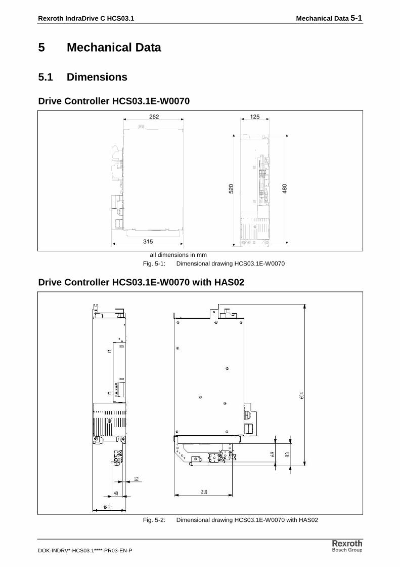
Drive Controller HCS03.1E-W0070
���
���
���
���
���
all dimensions in mmFig. 5-1: Dimensional drawing HCS03.1E-W0070
Drive Controller HCS03.1E-W0070 with HAS02
Fig. 5-2: Dimensional drawing HCS03.1E-W0070 with HAS02

5-2 Mechanical Data Rexroth IndraDrive C HCS03.1
DOK-INDRV*-HCS03.1****-PR03-EN-P
Drive Controller HCS03.1E-W0100, -W0150
���
���
���
��
���
���
all dimensions in mmFig. 5-3: Dimensional drawing HCS03.1E-W0100 and HCS03.1E-W150
Drive Controller HCS03.1E-W0100, -W0150 with HAS02
all dimensions in mmFig. 5-4: Dimensional drawing HCS03.1E-W0100 and HCS03.1E-W150 with
HAS02

Rexroth IndraDrive C HCS03.1 Mechanical Data 5-3
DOK-INDRV*-HCS03.1****-PR03-EN-P
Drive Controller HCS03.1E-W0210
���
���
��
���
���
��
all dimensions in mmFig. 5-5: Dimensional drawing HCS03.1E-W0210
Drive Controller HCS03.1E-W0210 with HAS02
all dimensions in mmFig. 5-6: Dimensional drawing HCS03.1E-W0210 with HAS02
5-4 Mechanical Data Rexroth IndraDrive C HCS03.1
DOK-INDRV*-HCS03.1****-PR03-EN-P
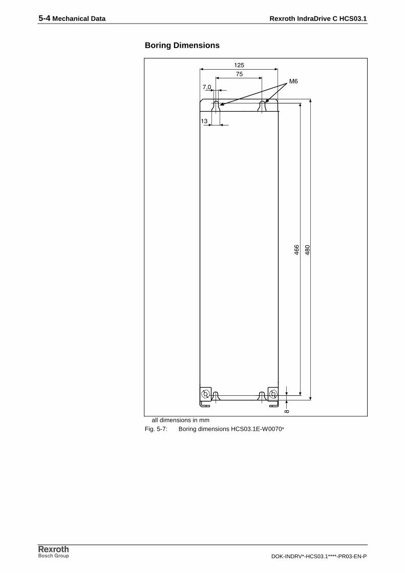
Boring Dimensions
���
��
�
��
���
���
�
��
all dimensions in mmFig. 5-7: Boring dimensions HCS03.1E-W0070*

Rexroth IndraDrive C HCS03.1 Mechanical Data 5-5
DOK-INDRV*-HCS03.1****-PR03-EN-P
���
�� ��
���
���
�
��
����
����
��
��
all dimensions in mmFig. 5-8: Boring dimensions HCS03.1E-W0100 and HCS03.1-W0150

5-6 Mechanical Data Rexroth IndraDrive C HCS03.1
DOK-INDRV*-HCS03.1****-PR03-EN-P
��
���
�
���
�����
��
����
���
����
��
all dimensions in mmFig. 5-9: Boring dimensions HCS03.1E-W0210
5.2 Weight
Device Weight in kg
HCS03.1E-W0070 13
HCS03.1E-W0100 20
HCS03.1E-W0150 20
HCS03.1E-W0210 38
Fig. 5-10: Weight of the devices
Note: The control section is not contained in the weight data.The weight of the control section is about 0.4 kg.

Rexroth IndraDrive C HCS03.1 Mechanical Data 5-7
DOK-INDRV*-HCS03.1****-PR03-EN-P
Mounting PositionDrive controllers and DC bus resistor unit should be mounted in such away that their longitudinal axis corresponds to the natural direction ofconvection (motor and power connections facing downwards).
In this way, natural convection supports the forced cooling air flow. Thisavoids the generation of pockets of heat in the drive controller.
Temperatures Above the Top of the DeviceThe drive controllers have a high efficiency. Outlet temperatures higherthan the ambient temperature are nevertheless produced at the top of thedevices, among other things due to the converted energies. High outlettemperatures are particularly produced in the case of insufficient coolingor when the cooling air current (blower failure) fails.
CAUTION
Risk of damage caused by too high outlettemperatures!⇒ When mounting and installing other components,
make sure the distance to the top of the drivecontrollers is sufficient.
⇒ You have to take into account that higher outlettemperatures can occur when the cooling air currentfails.
Outlet Temperatures
Designation Symbol Unit HCS03.1
temperature risewith distance of10 mm from top ofdevice
∆T K 30
Fig. 5-11: Outlet temperatures

5-8 Mechanical Data Rexroth IndraDrive C HCS03.1
DOK-INDRV*-HCS03.1****-PR03-EN-P

Rexroth IndraDrive C HCS03.1 Electrical Data 6-1
DOK-INDRV*-HCS03.1****-PR03-EN-P
6 Electrical Data
Note: The current and power data below apply when the allowedmotor cable length is complied with (see data in section "X5,Motor Connection"). They refer to 3AC400 V.
6.1 Power Section - Mains Supply
Designation Symbol Unit HCS03.1E-W0070
HCS03.1E-W0100
HCS03.1E-W0150
HCS03.1E-W0210
three-phase mainsconnection allowed
single-phase mainsconnection
not allowed
rotary field no rotary field condition
total power factor TPF atPDC with / without mainschoke
TPF 0,85/0,57 0,83/0,59 0,81/0,61 0,78/0,62
power factor offundamental componentDPF PDC with / withoutmains choke
cosφh1 0,95/0,64 0,95/0,67 0,94/0,70 0,93/0,73
assigned mains chokeHNL01.1E-
0571-N0050-A-500-NNNN
0362-N0080-A-500-NNNN
0240-N0106-A-500-NNNN
0170-N0146-A-500-NNNN
mains input voltage range ULN
V 3AC400…500 +10% -15%
mains frequency fLN
Hz 50…60 ± 2 Hz
mains input continuouscurrent at PDC cont
IL,cont
A 50 80 106 146
maximum inrush current(at max. input voltage)
IL, trans max
(on)
A 2,8 5,7 5,7 17
mains connection powerat PDC_cont;
ULN=AC400V; with
HNL01.1E
SLN
kVA 35 55,2 72,9 99,3
mains connection powerat PDC_cont;
ULN=AC400V; without
HNL01.1E
SLN
kVA 22,6 40,3 54 76
Fig. 6-1: Electrical data: power section - mains supply

6-2 Electrical Data Rexroth IndraDrive C HCS03.1
DOK-INDRV*-HCS03.1****-PR03-EN-P
6.2 Power Section - DC Bus
Designation Symbol Unit HCS03.1E-W0070
HCS03.1E-W0100
HCS03.1E-W0150
HCS03.1E-W0210
DC bus voltage range(unloaded)
UDC
V uncontrolledULN * 1,41
internal DC buscapacitance
CDC
mF 0,94 1,44 1,88 4,7
max. allowed external DCbus capacitance
CDCext
mF nicht zulässig 501)
limitation of inrush current charging via resistor;N/O contact: min. 250.000 switching actions
charging bymeans of phase
control1)
storable energy of theinternal DC bus capacitorsat 3AC400V
WDC
Ws 150 230 300 752
braking resistor switch-onthreshold
UDC
(R_DC On)
V 820…850 820…850 820…850 820…850
lower DC bus voltage limit(switch-off threshold)
UDC limit
(min)
V 400 400 400 400
upper DC bus voltage limit(switch-off threshold)
UDC limit
(max)
V 900 900 900 900
capacitance in DC busagainst ground; betweenL+ and L-
CY
nF 100 100 100 100
balancing factor for PDC
cont
(for parallel operation withcommon DC bus)with/without mains choke
- 1/0,8 1/0,8 1/0,8 1/0,8
rated power atULN = 400V
without mains chokeminimum inductance ofmains supply
PDC cont
Lmin
kW
µH
13
40
24
40
34
40
47
40
rated power atULN = 400V
with mains choke
PDC cont
kW 25 43 56 85
1): as of hardware index 03 (see type plate)Fig. 6-2: Electrical data: power section - DC bus

Rexroth IndraDrive C HCS03.1 Electrical Data 6-3
DOK-INDRV*-HCS03.1****-PR03-EN-P
6.3 Power Section - DC Bus Power
Designation Symbol Unit HCS03.1E-W0070
HCS03.1E-W0100
HCS03.1E-W0150
HCS03.1E-W0210
profile DC bus poweroverload operation
overload capacity:
base DC_
DC_peak
P
P=K
T
PDC_base
t
P
PDC_peak
t
DC bus peak powerULN = 3AC400 V, at Ta=40 °C; t=0,4 s; T=4 swithout mains chokewith mains choke
PDC_peak_1
kW
2040
3359
5489
68124
DC bus powerULN = 3AC400 V, at Ta=40 °C; t=0,4 s; T=4 swithout mains chokewith mains choke
PDC_base_1
kW
1020
1832
2440
3767
DC bus peak powerULN = 3AC400 V, at Ta=40 °C; t=2 s; T=20 swithout mains chokewith mains choke
PDC_peak_3
kW
1836
3053
5387
68124
DC bus powerULN = 3AC400 V, at Ta=40 °C; t=2 s; T=20 swithout mains chokewith mains choke
PDC_base_3
kW
1020
1629
2135
3564
DC bus peak powerULN = 3AC400 V, at Ta=40 °C; t=60 s; T=5 minwithout mains chokewith mains choke
PDC_peak_4
kW
1427
2544
4066
5294
DC bus powerULN = 3AC400 V, at Ta=40 °C; t=60 s; T=5 minwithout mains chokewith mains choke
PDC_base_4
kW
1121
1729
2439
3767
DC bus peak powerULN = 3AC400 V, at Ta=40 °C; t=60 s;T=10 minwithout mains chokewith mains choke
PDC_peak_5
kW
1427
2544
4066
5294
DC bus powerULN = 3AC400 V, at Ta=40 °C; t=60 s;T=10 minwithout mains chokewith mains choke
PDC_base_5
kW
1121
1729
2439
3767
Fig. 6-3: Electrical data: power section - DC bus power

6-4 Electrical Data Rexroth IndraDrive C HCS03.1
DOK-INDRV*-HCS03.1****-PR03-EN-P
WARNING
Damage due to drive controller overload!⇒ Make sure the specified performance data - peak
power and continuous power - are complied with bycorrect drive dimensioning and selective fusing in themains connection.
Mains Connection Power and DC Bus Continuous PowerThe diagrams below illustrate the interrelation between mains connectionpower (SLN) and DC bus continuous power (PDCcont) with and without theuse of mains chokes.
SLN depending on PDC cont
for HCS03.1-E-W0070 @3AC400V/4kHz
0,00
10,00
20,00
30,00
40,00
50,00
2,5 5 7,5 10 12,5 15 17,5 20 22,5 25 27,5 30
PDC cont [kW]
SL
N [
kVA
]
with mains choke without mains choke
Fig. 6-4: Interrelation of SLN / PDC for HCS03.1-E-W0070
SLN depending on PDC cont
for HCS03.1-E-W0100 @3AC400V/4kHz
0,00
10,00
20,00
30,00
40,00
50,00
60,00
70,00
0 10 20 30 40 50PDC cont [kW]
SL
N [
kVA
]
with mains choke without mains choke
Fig. 6-5: Interrelation of SLN / PDC for HCS03.1-E-W0100

Rexroth IndraDrive C HCS03.1 Electrical Data 6-5
DOK-INDRV*-HCS03.1****-PR03-EN-P
SLN depending on PDC cont
for HCS03.1-E-W0150 @3AC400V/4kHz
0,00
20,00
40,00
60,00
80,00
100,00
0 10 20 30 40 50 60 70
PDC cont [kW]
SL
N [
kVA
]
with mains choke without mains choke
Fig. 6-6: Interrelation of SLN / PDC for HCS03.1-E-W0150
SLN depending on PDC cont
for HCS03.1-E-W0210 @3AC400V/4kHz
0,00
20,00
40,00
60,00
80,00
100,00
120,00
0 10 20 30 40 50 60 70 80 90 100PDC cont [kW]
SL
N [k
VA
]
with mains choke without mains choke
Fig. 6-7: Interrelation of SLN / PDC for HCS03.1-E-W0210

6-6 Electrical Data Rexroth IndraDrive C HCS03.1
DOK-INDRV*-HCS03.1****-PR03-EN-P
6.4 Power Section - Braking Resistor
Designation Symbol Unit HCS03.1E-W0070
HCS03.1E-W0100
HCS03.1E-W0150
HCS03.1E-W0210
nominal brakingresistor
RDC(Bleeder) Ohm internally not contained
operating externalbraking resistor(optional)
allowed allowed allowed allowed
braking resistorswitch-on threshold
RDC (R_DC On) V see Functional Description of firmware
balancing factor forPBD
(for parallel operationwith common DC bus)
0,8 0,8 0,8 0,8
min. resistance valueof external brakingresistor
RDC(Bleeder) Ohm 17,5 11,7 7 5
allowed continuouspower of externalbraking resistor
Pcontchopper kW 13,2 18,9 25,2 42,6
ext. braking resistorpeak powerat ED=60% andt=120s
PBS kW 22 31,5 42 71
peak power brakechopper for t=1s
Ppeakchopper kW 42 63 97 137
Fig. 6-8: Data power section - braking resistor
60% 72120
peakchoppercontchopper
PP s
s= ×
Pcontchopper: brake chopper continuous powerPpeakchopper: brake chopper peak power
Fig. 6-9: Example for calculating brake chopper continuous power
Example for Calculating BrakeChopper Continuous Power
Rexroth IndraDrive C HCS03.1 Electrical Data 6-7
DOK-INDRV*-HCS03.1****-PR03-EN-P
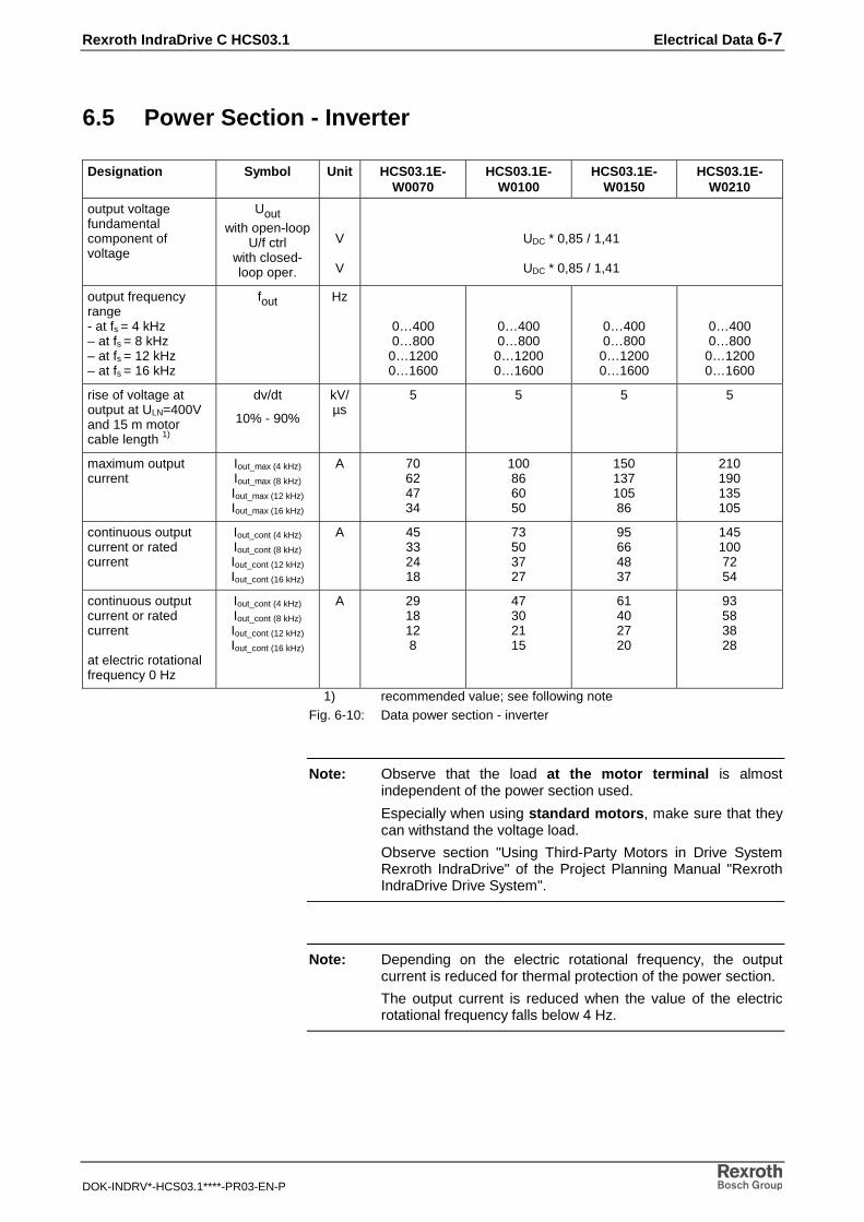
6.5 Power Section - Inverter
Designation Symbol Unit HCS03.1E-W0070
HCS03.1E-W0100
HCS03.1E-W0150
HCS03.1E-W0210
output voltagefundamentalcomponent ofvoltage
Uoutwith open-loop
U/f ctrlwith closed-loop oper.
V
V
UDC * 0,85 / 1,41
UDC * 0,85 / 1,41
output frequencyrange- at fs = 4 kHz– at fs = 8 kHz– at fs = 12 kHz– at fs = 16 kHz
fout Hz
0…4000…800
0…12000…1600
0…4000…800
0…12000…1600
0…4000…800
0…12000…1600
0…4000…800
0…12000…1600
rise of voltage atoutput at ULN=400Vand 15 m motorcable length 1)
dv/dt
10% - 90%
kV/µs
5 5 5 5
maximum outputcurrent
Iout_max (4 kHz)
Iout_max (8 kHz)
Iout_max (12 kHz)
Iout_max (16 kHz)
A 70624734
100866050
15013710586
210190135105
continuous outputcurrent or ratedcurrent
Iout_cont (4 kHz)
Iout_cont (8 kHz)
Iout_cont (12 kHz)
Iout_cont (16 kHz)
A 45332418
73503727
95664837
1451007254
continuous outputcurrent or ratedcurrent
at electric rotationalfrequency 0 Hz
Iout_cont (4 kHz)
Iout_cont (8 kHz)
Iout_cont (12 kHz)
Iout_cont (16 kHz)
A 2918128
47302115
61402720
93583828
1) recommended value; see following noteFig. 6-10: Data power section - inverter
Note: Observe that the load at the motor terminal is almostindependent of the power section used.
Especially when using standard motors, make sure that theycan withstand the voltage load.
Observe section "Using Third-Party Motors in Drive SystemRexroth IndraDrive" of the Project Planning Manual "RexrothIndraDrive Drive System".
Note: Depending on the electric rotational frequency, the outputcurrent is reduced for thermal protection of the power section.
The output current is reduced when the value of the electricrotational frequency falls below 4 Hz.

6-8 Electrical Data Rexroth IndraDrive C HCS03.1
DOK-INDRV*-HCS03.1****-PR03-EN-P
6.6 Power Section - Examples of Allowed Output CurrentProfiles
The capacity of the drive controllers when operated with mains choke isdescribed below with examples of load profiles.
Designation Symbol Unit HCS03.1E-W0070
HCS03.1E-W0100
HCS03.1E-W0150
HCS03.1E-W0210
output current profilefor overloadoperation
overload capacity:
Iout_baseIout_peak
=K
T
Iout_base
t
I
Iout_peak
t
maximum outputcurrentt=400ms; T=4s
Iout_peak1 (4 kHz)
Iout_peak1 (8 kHz)
Iout_peak1 (12 kHz)
Iout_peak1 (16 kHz)
A 70
50
36
28
100
70
50
40
150
100
75
60
210
150
100
75
base load currentavailable atmaximum currentt=400ms; T=4s
Iout_base1 (4 kHz)
Iout_base1 (8 kHz)
Iout_base1 (12 kHz)
Iout_base1 (16 kHz)
A 35
25
18
14
54
37
28
19
67
50
36
26
116
78
59
45
maximum outputcurrentt=2s; T=20s
Iout_peak3 (4 kHz)
Iout_peak3 (8 kHz)
Iout_peak3 (12 kHz)
Iout_peak3 (16 kHz)
A 63
45
32
23
90
65
45
32
147
100
70
50
210
150
100
80
base load currentavailable atmaximum currentt=2s; T=20s
Iout_base3 (4 kHz)
Iout_base3 (8 kHz)
Iout_base3 (12 kHz)
Iout_base3 (16 kHz)
A 35
25
19
15
49
30
25
21
59
44
35
28
109
73
57
41

Rexroth IndraDrive C HCS03.1 Electrical Data 6-9
DOK-INDRV*-HCS03.1****-PR03-EN-P
Designation Symbol Unit HCS03.1E-W0070
HCS03.1E-W0100
HCS03.1E-W0150
HCS03.1E-W0210
maximum outputcurrentt=60s; T=5min
Iout_peak4 (4 kHz)
Iout_peak4 (8 kHz)
Iout_peak4 (12 kHz)
Iout_peak4 (16 kHz)
A 47
34
25
19
75
52
38
28
111
80
60
45
160
110
80
60
base load currentavailable atmaximum currentt=60s; T=5min
Iout_base4 (4 kHz)
Iout_base4 (8 kHz)
Iout_base4 (12 kHz)
Iout_base4 (16 kHz)
A 37
23
16
10
50
34
21
19
66
42
28
22
115
80
55
42
maximum outputcurrentt=60s; T=10min
Iout_peak5 (4 kHz)
Iout_peak5 (8 kHz)
Iout_peak5 (12 kHz)
Iout_peak5 (16 kHz)
A 47
34
25
19
75
52
38
28
111
80
60
45
160
110
80
60
base load currentavailable atmaximum currentt=60s; T=10min
Iout_base5 (4 kHz)
Iout_base5 (8 kHz)
Iout_base5 (12 kHz)
Iout_base5 (16 kHz)
A 37
23
16
10
50
34
21
19
66
42
28
22
118
82
56
43
Fig. 6-11: Technical data for power section
Note: The load profiles are characterized by their time flow and thecorresponding currents and represent the output currentcapacity. These profiles are limited by the drive controller viathe thermal effect of the output current. When the currentlimitation is triggered, it is therefore necessary to compare theactual load with the above data and, if necessary,
• reduce the load with Iout_max or
• reduce the pulse time or
• increase the cycle time or
• reduce the switching frequency fs or
• use a device with higher type current
(See also Functional Description and Troubleshooting Guideof the firmware.)
Note: The load profiles are available if particularly the maximumcurrent at switching frequencies of 8, 12 and 16 kHz isexternally (e.g. by the control unit) limited to the indicatedvalues.

6-10 Electrical Data Rexroth IndraDrive C HCS03.1
DOK-INDRV*-HCS03.1****-PR03-EN-P
6.7 Power Section - Operating Standard Motors
The following table specifies the nominal power PNenn of 4-pole standardmotors, which can be operated with the respective drive controller. Thereapply following conditions:
• the dedicated mains choke is used
• switching frequency: 4 kHz
• output frequency: > 4 Hz
• ambient temperature: Ta < Tamax °C
• control factor: a0 > 0,8
• relation of overload: K =peak baseP P
ULN = 3AC400V, 48…62 Hz:
Designation Symbol Unit HCS03.1E-W0070 1)
HCS03.1E-W0100 1)
HCS03.1E-W0150 1)
HCS03.1E-W0210 1)
standard motor nominal power foroverload operation:t=2 s; T=20 s; K=2,0
PNenn kW 15 22 33 55
standard motor nominal power foroverload operation:t=60 s; T=5 min; K=1,5
PNenn kW 15 22 33 55
standard motor nominal power foroverload operation:t=60 s; T=10 min; K=1,1
PNenn kW 18,5 27 35 60
standard motor nominal power forcontinuous operation:t>10 min; K=1,0
PNenn kW 22 37 45 75
1) preliminary dataFig. 6-12: Standard motors 3AC400V, 50 Hz
ULN = 3AC460…480V, 48…62 Hz
Designation Symbol Unit HCS03.1E-W0070 1)
HCS03.1E-W0100 1)
HCS03.1E-W0150 1)
HCS03.1E-W0210 1)
standard motor nominal power foroverload operation:t=2 s; T=20 s; K=2,0
PNenn kW 15 22 33 55
standard motor nominal power foroverload operation:t=60 s; T=5 min; K=1,5
PNenn kW 15 22 33 55
standard motor nominal power foroverload operation:t=60 s; T=10 min; K=1,1
PNenn kW 18,5 27 35 60
standard motor nominal power forcontinuous operation:t>10 min; K=1,0
PNenn kW 22 37 45 75
1) preliminary dataFig. 6-13: Standard motors 3AC460V, 60 Hz
Rexroth IndraDrive C HCS03.1 Electrical Data 6-11
DOK-INDRV*-HCS03.1****-PR03-EN-P
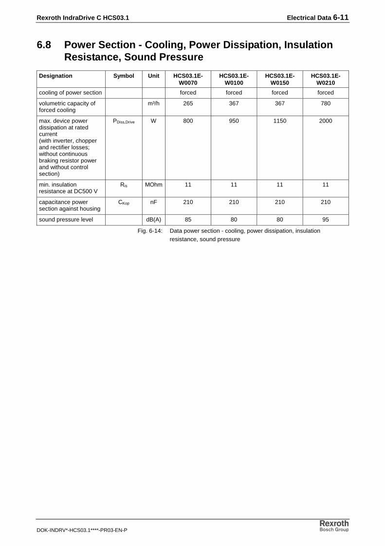
6.8 Power Section - Cooling, Power Dissipation, InsulationResistance, Sound Pressure
Designation Symbol Unit HCS03.1E-W0070
HCS03.1E-W0100
HCS03.1E-W0150
HCS03.1E-W0210
cooling of power section forced forced forced forced
volumetric capacity offorced cooling
m³/h 265 367 367 780
max. device powerdissipation at ratedcurrent(with inverter, chopperand rectifier losses;without continuousbraking resistor powerand without controlsection)
PDiss,Drive W 800 950 1150 2000
min. insulationresistance at DC500 V
Ris MOhm 11 11 11 11
capacitance powersection against housing
CKop nF 210 210 210 210
sound pressure level dB(A) 85 80 80 95
Fig. 6-14: Data power section - cooling, power dissipation, insulationresistance, sound pressure

6-12 Electrical Data Rexroth IndraDrive C HCS03.1
DOK-INDRV*-HCS03.1****-PR03-EN-P
6.9 Control Voltage
Devices with Control Voltage Generation from DC Bus (HCS03.1E-W0xxx-NNxV)
The internally generated control voltage is used for stand-alone supply ofthe drive controller or for buffering in case the external 24V supply fails. Itis not used for supplying motor holding brakes.
(Data based on an ambient temperature of 25 °C)
Designation Symbol Unit Value
external control voltage supply UN3 V 24 ±20%(if no motor holding brake has to be supplied)
If motor holding brakes are to be supplied, observe thedata of the motor documentation. The following valuesare normally sufficient:24 ±5% with motor cable length < 50 m26 ±5% with motor cable length > 50 m
max. ripple content w - mustn't exceed the control voltage range
max. allowed overvoltage UN3maxV 33 (max. 1 ms)
max. inrush current IEIN3A 2,8
plus inrush current of control section (see Project PanningManual IndraDrive Control Sections)
max. pulse width of IEIN3 tEIN3Ladems 5
max. input capacitance CN3mF 1,2 * 0,47
power consumption (in the case of external supply)*:
HCS03.1E-W0070 PN3W approx. 22.5
HCS03.1E-W0100 PN3W approx. 25
HCS03.1E-W0150 PN3W approx. 25
HCS03.1E-W0210 PN3W approx. 30
internally generated controlvoltage
UN3 V 24 ±10%
(not used for supplying the motor holding brake)
*: data without motor holding brake and control section taken intoaccount
Fig. 6-15: Control voltage
Note: Overvoltage of more than 33V has to be discharged by meansof the appropriate electrical equipment of the machine orinstallation.This includes:
• 24V power supply units that reduce incoming overvoltagesto the allowed value.
• Overvoltage limiters at the control cabinet input that limitexisting overvoltage to the allowed value. This, too,applies to long 24V lines that have been run in parallel topower cables and mains cables and can absorbovervoltages by inductive or capacitive coupling.

Rexroth IndraDrive C HCS03.1 Electrical Data 6-13
DOK-INDRV*-HCS03.1****-PR03-EN-P
Block Diagram of Control Voltage Generation from theDC Bus
�� �
���������������
�� �� �� �������� ��
Br: brake circuitLT: power sectionST: control sectionSMPS: internal switching-mode power supplyZK: DC bus
Fig. 6-16: Block diagram of internal control voltage generation

6-14 Electrical Data Rexroth IndraDrive C HCS03.1
DOK-INDRV*-HCS03.1****-PR03-EN-P
6.10 Connections
Overall Connection Diagram
!���!" #
��� ���$�%& $
'��������(�����
)��*$ !
���!""$�
�! %!
""!+��,
)��*$ !
���!"
� -
� .
/!+$� *!"�&,$
0�$�1��&" 2&�3
�� 2#4
� -
� .
-��
� � �
!���!" *!"�&,$
0�$�1��&" 2&�3
-��
�
� �
/!+$� !�
�$ ��!�
��22!
� &
2"$
2#4 !
��$
��!�
�� � � � �
��22!
� &
2"$
2#4 !
��$
��!�
��
'� . �
!�!�
����
���
��
��
���
��
!/��!
�&"5
�
�
�
�
�
�
� �'
�
�
�
��
6!")��,
2�&7
$
�
8
-�����
����
��� 9
(�� 9
��:��
0�� )$/
$�)$
� $ !%
1!�!� �5
/$3
;
46�$") 4#/
/!��
�!�!� &2
"$
�!��$1/-
�!��$1/.
�
'�
'�
'�
�
����
��
��
2�&7
$.�$4�4�!�
� �
��
/!+$� *!"�&,$
0�$�1��&" 2&�3
�� 2#4
!���!" *!"�&,$
0�$�1��&" 2&�3
%�!1
)��*$ !
���!"
Fig. 6-17: Overall connection diagram

Rexroth IndraDrive C HCS03.1 Electrical Data 6-15
DOK-INDRV*-HCS03.1****-PR03-EN-P
6.11 Connections at Power Section HCS03.1
Overview
���
��
�-
�. �.
�-<� <���
<�
�
�
�
�� �
�
�
���
'� '� '� �� �� ��
��
Fig. 6-18: Connections at power section HCS03.1

6-16 Electrical Data Rexroth IndraDrive C HCS03.1
DOK-INDRV*-HCS03.1****-PR03-EN-P
No. Designation Design Connectionobligatory?
Note on terminal description
1 Module bus X1 Ribbon cable no The module bus connection is onlynecessary if a converter of identical ratingor an inverter is connected to L+ and L-.
1.1 Park position X1
2 Control voltage; +24 Vand 0 V
Bars yes (forcompliance
with UL termsand utilizationof integrated
safetytechnology)
Connection of an external 24 V supply isonly necessary if an external mainscontactor or a holding brake is used.If connection with bars is not possible,short twisted wires may be used as analternative.
3 DC bus; L+ and L- Bars no Connection is only necessary if twoconverters of identical rating are to belinked via the DC bus or if an inverter isconnected.If connection with bars is impossible, linesmay be used as an alternative.
4 Connection of equipmentgrounding conductor
Joint bar yes If connection with joint bar is impossible,lines may be used as an alternative.
5 Motor (X5) yes 4 connections: A1, A2, A3, PE
6 Shield connection of motorcable
Shielded motorcable
yes Alternatively, shield connection can berealized via the mounting plate availableas an option.
7 Motor temperaturemonitoring and motorholding brake (X6)
Shielded cable orshielded motor
cable withintegrated
connection cablefor X6
no This connection is only required if themotor is equipped with temperaturemonitoring function and/or holding brakeand if these functions are to be used.
8 Mains connection Single cores or4-core non-
metallic-sheathed cable
yes
9 Braking resistor connection Single cores no
Fig. 6-19: Connections at power section (overview)

Rexroth IndraDrive C HCS03.1 Electrical Data 6-17
DOK-INDRV*-HCS03.1****-PR03-EN-P
HCS03.1E
�!�!�. !��$ ��!�
/!+$� !��$ ��!�
��. !��$ ��!�
���
��
�-
�. �.
�-
��. !��$ ��!�
'��������(�����
Fig. 6-20: Connections at power section (front) HCS03.1E-W0100…210�
��
�
8�
8
8$
9��9��9��&�
���������&�
X3: Mains connectionX5: Motor connectionX6: Connection of motor temperature, motor holding brake
Fig. 6-21: Connections at power section (bottom) HCS03.1E-W0070

6-18 Electrical Data Rexroth IndraDrive C HCS03.1
DOK-INDRV*-HCS03.1****-PR03-EN-P
Optional Control VoltageControl voltage is supplied by an external 24V power supply unit.
Note: Technical data of control voltage: See page 6-12
The control voltage supply is connected via contact bars and screws (M6)at the front of the drive controller (cross section of a contact bar:6 x 12 mm). Depending on the width of the drive controllers, there arecontact bars of different lengths.
6 Nm
DC BusBy means of the DC bus connection, the following components are linked:
• the converter to other inverters
• external additional capacitors are not allowed (except –W0210)
The DC bus is connected via contact bars and screws (M6) at the front ofthe drive controller (cross section of a contact bar: 6 x 12 mm).Depending on the width of the drive controllers, there are contact bars ofdifferent lengths.
6 Nm
If in special cases it is not possible to use the DC bus rails for connection,connection must be established using the shortest possible twisted wires.
Length of twisted wire max. 4 m
Wire cross section minimum 10 mm2 (AWG 8)but not less than supply feedercross section
Wire protection by means of fuses in the mainssupply
Dielectric strength of single strand againstground
> 750 V DC(e.g.: strand type – H07)
CAUTION
Damage caused by voltage arcing!⇒ When electrical lines and not the contact bars are
used to connect the converter, the connections mustbe executed correctly.
CAUTION
Damage caused by voltage arcing!⇒ If drive controllers are stacked in the control cabinet,
the connections for the DC buses between the drivecontrollers have to be correctly made.
Design
Tightening Torque
Design
Tightening Torque
DC Bus Wiring
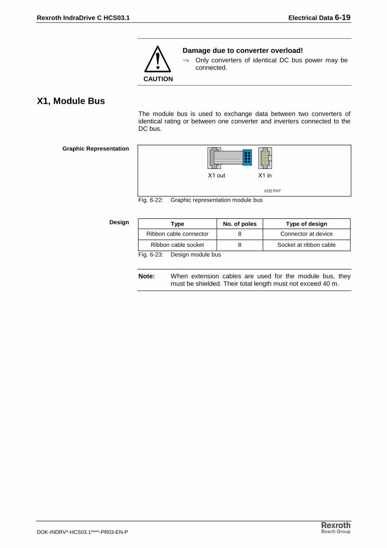
Rexroth IndraDrive C HCS03.1 Electrical Data 6-19
DOK-INDRV*-HCS03.1****-PR03-EN-P
CAUTION
Damage due to converter overload!⇒ Only converters of identical DC bus power may be
connected.
X1, Module BusThe module bus is used to exchange data between two converters ofidentical rating or between one converter and inverters connected to theDC bus.
X1f2.FH7
8��� 8����
Fig. 6-22: Graphic representation module bus
Type No. of poles Type of design
Ribbon cable connector 8 Connector at device
Ribbon cable socket 8 Socket at ribbon cable
Fig. 6-23: Design module bus
Note: When extension cables are used for the module bus, theymust be shielded. Their total length must not exceed 40 m.
Graphic Representation
Design

6-20 Electrical Data Rexroth IndraDrive C HCS03.1
DOK-INDRV*-HCS03.1****-PR03-EN-P
X3, Mains ConnectionOperation in IT mains is possible without restrictions up to a pulsefrequency = 8 kHz. Operation at a pulse frequency of > 8 kHz is notallowed.
For operation in grounded IT mains take into account that when filter HNKis used, leakage currents can occur which might trigger circuit breakers orearth-leakage monitors.
Install an isolating transformer.
HCS03.1E- Type No. of poles Type of design
W0070 Connector 4 Screw connection
W0100 Terminal block 3 Screw connection for M6 ringcable lugs
W0150 Terminal block 3 Screw connection for M6 ringcable lugs
W0210 Terminal block 3 Screw connection for M10 ringcable lug
Fig. 6-24: Design mains connection
Identification of the individual connections:
Identification Significance
L1 phase 1
L2 phase 2
L3 phase 3
(PE) equipment grounding conductor
Fig. 6-25: Identification of the individual connections mains connection
HCS03.1E- Cross section
[mm²]
Cross sectionflexible[mm²]
Cross section
AWG
W0070 16 - 6
W0100 35 - 2
W0150 50 2*25 0
W0210 95 2*50 4/0
Fig. 6-26: Connection cross sections mains connection
HCS03.1E- Tightening torque [Nm]
W0070 1.5
W0100 6
W0150 6
W0210 18
Fig. 6-27: Tightening torques mains connection
Remedy
Design
Connection Cross Section
Tightening Torque

Rexroth IndraDrive C HCS03.1 Electrical Data 6-21
DOK-INDRV*-HCS03.1****-PR03-EN-P
DANGER
Dangerous movements caused by unbrakedcoasting to stop of the motor in case supplyvoltage fails!⇒ Do not stay within the motional range of the machine.
Possible measures to prevent personnel accidentallyaccessing the machine:- protective fencing- protective grid- protective cover- light barrier.
⇒ Fencing and covers must be adequately securedagainst the maximum possible force of movement.
X5, Motor Connection
HCS03.1E- Type No. ofpoles
Type of design
W0070 Connector 4 Screw connection
W0100 Terminal block 3 Screw connection for M6 ringcable lugs
W0150 Terminal block 3 Screw connection for M6 ringcable lugs
W0210 Terminal block 3 Screw connection for M10 ringcable lugs
Fig. 6-28: Design motor connection
Identification of the individual connections:
Identification Significance
A1 phase 1
A2 phase 2
A3 phase 3
(PE) equipment grounding conductor
Fig. 6-29: Identification of the individual connections motor connection
HCS03.1E- Cross section
[mm²]
Cross sectionflexible[mm²]
Cross section
in AWG
W0070 16 - 6
W0100 35 - 2
W0150 50 2*25 0
W0210 95 2*50 4/0
Fig. 6-30: Connection cross sections motor connection
Design
Connection Cross Section

6-22 Electrical Data Rexroth IndraDrive C HCS03.1
DOK-INDRV*-HCS03.1****-PR03-EN-P
HCS03.1E- Tightening torque [Nm]
W0070 1.5
W0100 6
W0150 6
W0210 18
Fig. 6-31: Tightening torques motor connection
CAUTION
Damage to the drive controller!⇒ Strain relief for the motor power cables cannot be
provided at the drive controller. Therefore, makesure strain relief of the motor power cables isprovided in the control cabinet.
For the connection between drive controller and motor, use Rexroth motorpower cables.
The Rexroth motor power cable comprises:
• three conductors for motor power connection
• one conductor for equipment grounding connection
• a separately shielded pair of conductors for motor temperaturemonitoring
• a separately shielded pair of conductors for motor holding brake
• an overall shield to be applied to shield contact.
Alternatively the cable can be composed of four twisted single wires(3 phases, 1 equipment grounding conductor) with separately guided,shielded wires for temperature monitoring and connecting the brake.
Note: For more details on the technical data, connection and crosssection, please refer to the respective motor description.
To avoid overload of the drive controller the motor cable length is limitedat a switching frequency > 4 kHz.
The lengths indicated in the table below are recommended as guidevalues (at an ambient temperature of ≤ 40 °C in accordance withEN 60 204).
Allowed line lengths for motor connection without filter measures atmotor output:
Drive controller switchingfrequency
Max. length for 2nd environment(industrial area), EN61800-3
4 kHz 75 m
8 kHz 50 m
12 kHz 25 m
16 kHz 18 m
Fig. 6-32: Cable lengths
Tightening Torque
Connection of the Motor PowerCable
Data of the Motor Cable

Rexroth IndraDrive C HCS03.1 Electrical Data 6-23
DOK-INDRV*-HCS03.1****-PR03-EN-P
Note: If greater cable lengths are required, the additional componentHMF01.1 must be used. The maximum allowed cable length with HMF01.1 is 200 m,the maximum allowed switching frequency of the drivecontroller in this case has to be limited to 4 kHz.
Note: If two motor cables connected in parallel are used betweendrive controller and motor, the maximum allowed length of themotor cable is reduced by half.
X6, Motor Temperature Monitoring and Motor Holding Brake
4
3
2
1
Fig. 6-33: Terminal X6
Type No. of poles Type of design
Spring tension 4 Pins on device
Fig. 6-34: Design X6
1 MotTemp+
2 MotTemp-Motor temperature monitoring
3 +24 V
4 0 VMotor holding brake
Fig. 6-35: Pin assignment X6
HCS03.1E-W0070:
Cross sectionsingle-wire
[mm²]
Cross sectionmulti-wire
[mm²]
Cross section
in AWG
1,5 1,5 16
Fig. 6-36: Connection cross section X6 (HCS03.1E-W0070)
HCS03.1E-W0100, -W0150 and -W0210:
Cross sectionsingle-wire
[mm²]
Cross sectionmulti-wire
[mm²]
Cross section
in AWG
2,5 2,5 12
Fig. 6-37: Connection cross-section X6 (HCS03.1E-W0100…0210)
Note: The brake is supplied via the optional 24 V control voltage.
Graphic Representation
Design
Connection
Connection Cross Section

6-24 Electrical Data Rexroth IndraDrive C HCS03.1
DOK-INDRV*-HCS03.1****-PR03-EN-P
'��������(�����
=$>�!�6'�.�!�!��
�
'� '� '�
' � � �
��
6!")��,.2�&7$?
��� 9(�� 9��:��
0�� )$/$� $ !% 1!�!��5/$3
46�$") 4#//!��1!�!� &2"$
� 8
;
� �
��!��$
1/-
��!��$
1/.
�-�
����
���
��
*: Holding brake (optional)Fig. 6-38: Connection of motor temperature monitoring and motor holding
brake
ATTENTION
Maximum allowed braking current:• W0070: 2 A
• W0100: 2 A
• W0150: 2 A
• W0210: 2 A
Where braking currents are higher, the motor holdingbrake must be activated by means of an external contactelement.
Note: With the HCS03.1 devices it is possible to operate a motorbrake with a switching frequency of 0.5 Hz.
Note: The output to the motor holding brake (+24 V, 0 V) isprotected against overload and short-circuit by means of aninternal electronic switch.

Rexroth IndraDrive C HCS03.1 Electrical Data 6-25
DOK-INDRV*-HCS03.1****-PR03-EN-P
DANGER
Dangerous movements! Danger to personnelfrom falling or dropping axes!⇒ The standard motor holding brake provided or an
external motor holding brake controlled directly bythe drive controller are not sufficient on their own toguarantee the safety of personnel!
⇒ Personnel safety must be achieved using higher-ranking, fail-safe procedures:• Dangerous areas should be blocked off with
protective fences or grids.• Additionally secure vertical axes against falling or
sinking after switching off the motor power by,for example:- mechanically locking the vertical axis
- providing external braking/catching/clampingmechanisms
- adequately counterbalancing the axis.
For the current consumption of the motor holding brake see the projectplanning documentation for the AC motors.
The motor holding brake of the AC motors has not been designed as aservice brake. After approximately 20,000 motor revolutions against theclosed brake armature disc it will be worn.
The drive controller can assume the control of the motor holding brake.
Note: If the drive controller controls the brake, external supply with+24V is required.
Note: For operating Rexroth motors with motor brake, externalsupply of 24 V +/-10 % is required (please also take the datasheet of the motors into account).
Note: In the condition as supplied, control is not activated.
Controlling the Motor HoldingBrake

6-26 Electrical Data Rexroth IndraDrive C HCS03.1
DOK-INDRV*-HCS03.1****-PR03-EN-P
X9, Braking Resistor
HCS03.1E- Type No. of poles Type of design
W0070 Connector 2 Screw connection
W0100 Screw terminal block 2 Screw connection
W0150 Screw terminal block 2 Screw connection
W0210 Screw terminal block 2 Screw connection
Fig. 6-39: Design X9 braking resistor
Identification of the individual connections:
Identification Significance
1 connection of chopper IGBT
2 DC bus L+
Fig. 6-40: Identification of the individual connections X9 braking resistor
HCS03.1E- Cross sectionin [mm²]
Cross sectionin AWG
W0070 16 6
W0100 25 4
W0150 25 4
W0210 50 0
Fig. 6-41: Connection cross sections X9 braking resistor
HCS03.1E- Tightening torque [Nm]
W0070 1.5
W0100 2
W0150 2
W0210 8
Fig. 6-42: Tightening torques X9 braking resistor
Note: With twisted or shielded cable, the maximum cable length forthe braking resistor is 5 m.
Design
Connection Cross Section
Tightening Torque

Rexroth IndraDrive C HCS03.1 Electrical Data 6-27
DOK-INDRV*-HCS03.1****-PR03-EN-P
XS1, Shield Connection
'(�������(�����
Fig. 6-43: Shield connection XS1
Connection for shields of lines connected to the control section (only forlines with connectors, which do not have their own shield connection).
Note: Always connect shields of control lines with a large metal-to-metal contact surface.
Ground Connection of HousingThe ground connection of the housing is used to provide functional safetyof the drive controllers and protection against contact in conjunction withthe equipment grounding conductor.
Ground the housings of the drive controllers:
1. Connect the bare metal back panel of the drive controller inconductive form to the mounting surface in the control cabinet. To dothis use the supplied mounting screws.
2. Connect the mounting surface of the control cabinet in conductiveform to the equipment grounding system.
See also Project Planning Manual of drive system, chapter "SystemConnections of the Components"

6-28 Electrical Data Rexroth IndraDrive C HCS03.1
DOK-INDRV*-HCS03.1****-PR03-EN-P
Connection Point of Equipment Grounding Conductor
DANGER
Lethal electric shock caused by live parts withmore than 50 V!⇒ Connect the drive controller to the equipment
grounding system.⇒ Via the joint bar on the front connect the drive
controller to the neighboring drive controller.
See also Project Planning Manual of drive system, chapter "SystemConnections of the Components"
masseanschluss_frontf2
1
1: joint barFig. 6-44: Equipment grounding connection to neighboring device
Note: Cables used for connection of the equipment groundingconductor must have a cross section of at least 10 mm2
(however not smaller than the supply feeder cross section).
The joint bar is mounted by means of screws (M6 x 25).
6 Nm
Design
Tightening Torque

Rexroth IndraDrive C HCS03.1 Touch Guard 7-1
DOK-INDRV*-HCS03.1****-PR03-EN-P
7 Touch Guard
WARNING
Lethal electric shock caused by live parts withmore than 50 V!⇒ The appropriate touch guard must be mounted for
each drive controller following connection work.⇒ Never mount a damaged touch guard.⇒ Immediately replace a damaged touch guard by an
undamaged touch guard.
Cutouts
�30:!�� ���06� ;:0�������
A
B C
Fig. 7-1: Cutouts at the touch guard
WARNING
Lethal electric shock caused by live parts withmore than 50 V!⇒ You have to provide the best possible protection
against contact. Therefore keep the cutouts at thetouch guard as small as possible.
⇒ Only break off the cutouts if necessary.
• If the DC bus and the control voltage are connected by means ofcontact rails, only the cutout C (see picture) may be broken off thetouch guard.
• If the DC bus and the control voltage are connected by means ofcables (e.g. in the case of multiple-line arrangement of the drivecontrollers), the cutouts A, B and C (see picture) may be broken offthe touch guard.
• At the first and last drive controller in a line of drive controllersconnected to each other there mustn't any cutout be broken off at theouter side of the touch guard.

7-2 Touch Guard Rexroth IndraDrive C HCS03.1
DOK-INDRV*-HCS03.1****-PR03-EN-P
Mounting
���������������
���
�
Fig. 7-2: Touch guard
The touch guard must always be mounted following connection work.
Note: Risk of damage to the touch guard!
The maximum tightening torque for the fixing screw for thetouch guard is 2.8 Nm.

Rexroth IndraDrive C HCS03.1 Replacing Devices 8-1
DOK-INDRV*-HCS03.1****-PR03-EN-P
8 Replacing Devices
8.1 General Information
The diagnostic display enables aimed and effective troubleshooting inorder to:
• avoid production downtimes due to extensive searches in individualdevices and repairs of devices in the installation.
• start operating the installation again without extensive assembly andadjustments.
• quickly eliminate the problem and easily replace defective drivecomponents.
When returning a defective device to our Customer Service, pleaseenclose the completed Fault Report. The Fault Report is included in thischapter and may be copied for your convenience.
Note: The new drive component must have the same typedesignation as the faulty device. To ensure this, indicate theentire type designation when requesting replacement parts.
8.2 How to Proceed When Replacing Devices
Note: For replacing devices you absolutely have to observe thesafety instructions contained in chapter 3!
Replacing the Drive Controller• save parameter set
• open main switch
• make sure main switch cannot be switched on again
• make sure drive controller is completely de-energized
DANGER
Lethal electric shock caused by contact to liveparts!⇒ Before touching live parts allow the capacitors to
discharge! Only then start working on the connectioncables!
• remove touch guard and separate connecting lines from drivecontroller
• unscrew screws on top and bottom of housing
• take drive controller out of drive system
• mount new drive controller
• connect new drive controller as specified in machine circuit diagram
• mount touch guard
• copy firmware and parameter set to new drive controller (see firmwaredocumentation)

8-2 Replacing Devices Rexroth IndraDrive C HCS03.1
DOK-INDRV*-HCS03.1****-PR03-EN-P
Replacing the Motor• open main switch
• make sure main switch cannot be switched on again
• disconnect plug-in connectors
Note: When replacing the motor, cover the open mating sites ofpower lines with protective caps if sprinkling with coolingliquid/lubricant or soiling may occur (allowed degree of soilingaccording to EN50178: 2).
• replace motor
Note: To mechanically replace the AC servo motor, observe theinstructions of the machine manufacturer.
• connect plug-in connectors
ATTENTION
Risk of accident due to accidental axismovement!⇒ Servo axes with indirect distance measuring system
via the motor encoder will loose the position datareference when the motor is replaced!This position data reference to the machinecoordinate system must therefore be reestablishedafter replacement.
• for servo axes with absolute motor encoder, reestablish the positiondata reference

Rexroth IndraDrive C HCS03.1 Replacing Devices 8-3
DOK-INDRV*-HCS03.1****-PR03-EN-P
Replacing Cables
ATTENTION
Lethal electric shock caused by live parts withmore than 50 V!⇒ Power connectors of the cables may only be
separated or connected if the installation has beende-energized!
Note: When replacing cables, observe the instructions of themachine manufacturer.If you do not use ready-made Rexroth cables, check to ensurethat the cables match the terminal diagram of the machinemanufacturer!
• open main switch
• make sure main switch cannot be switched on again
• disconnect plug-in connectors
Note: When replacing cables, cover the open mating sites of powerlines with protective caps if sprinkling with coolingliquid/lubricant or soiling may occur (allowed degree of soilingaccording to EN50178: 2).
• replace cable
ATTENTION
Property damage caused by bad powerconnectors!⇒ Only connect clean and dry power connectors.
• connect plug-in connectors

8-4 Replacing Devices Rexroth IndraDrive C HCS03.1
DOK-INDRV*-HCS03.1****-PR03-EN-P
8.3 Fault Report
Fault Reportfor Drive Systems
Date:Report No.:
This fault report is intended to help eliminate problems that might possibly be related to drive systems.
Please fill it out carefully and send it, together with the parameter file with which the fault occurred, toBosch Rexroth.
Contact person:
Customer (machine manufacturer):
End customer:
Branch of industry:
Telephone:
Fax:
E-mail: @
System description:Firmware
Firmware version:
FWA- - - V -MS
Software:
DriveTop version: SWA-DTOP**-INB- V -MS
Operating system:
Service pack:
Language:
PC designation:
Hardware configuration (system RAM, harddisk memory,...):
Drive system
Power section:
Type code: - - - -
Serial number: SN
Hardware index:
Control section:
Type code: - - - - - - -
Serial number: SN
Hardware index:
Supply module:
Type code: - - - -
Serial number:
Motor
Type designation:
Serial number: S.No.
Motor encoder:
Mounting position:
Additional components (e.g. control system involved,external encoder, filter, cooling system in controlcabinet,...):
Fault description (detailed description of situation before, during and after fault occurred):
To quickly resolve your problem we ask you to send us also the parameter set with which the fault occurred.
Name of parameter set file:

Rexroth IndraDrive C HCS03.1 Replacing Devices 8-5
DOK-INDRV*-HCS03.1****-PR03-EN-P
General conditions:Mode at time fault occurred: Parameterization mode
Operating mode Switch phase
Operating mode active at time fault occurred: ,Encoder ,
7-segment display... ...before fault occurred: ...after fault occurred:
Fault status occurs permanently occurs during commissioning occurs sporadically occurs after approx. hours occurs with shocks depends on temperature
Causes unknown incorrect connection external cause mechanical damage loose cable connection moisture in unit foreign body in unit
Other defects problems in the mechanical system power section failure control system failure motor failure cable break defective blower defective feedback
Wiring / mechanical setup (e. g. length of cables, grounding, assembly,...):
Information on the machine (e. g. operating hours, type, serial number,...):
Mains conditions (e. g. frequency, voltage,...):
Ambient conditions (e. g. ambient temperature, humidity,...):
In case of problems with DriveTop
Name of dialog in which fault occurred:
Drive connection:
Note: In order to resolve your DriveTop problem quickly, we would like to ask you to send us the file"debug.log". You can find it in the DriveTop directory.
Fig. 8-1: Fault report

8-6 Replacing Devices Rexroth IndraDrive C HCS03.1
DOK-INDRV*-HCS03.1****-PR03-EN-P

Rexroth IndraDrive C HCS03.1 Disposal and Environmental Protection 9-1
DOK-INDRV*-HCS03.1****-PR03-EN-P
9 Disposal and Environmental Protection
9.1 Disposal
ProductsOur products can be returned to us free of charge for disposal. However,the products must be free of oil, grease or other dirt.
Furthermore, the products returned for disposal must not contain anyundue foreign matter or foreign component.
Please send the products free domicile to the following address:
Bosch Rexroth AGElectric Drives and ControlsBürgermeister-Dr.-Nebel-Straße 2D-97816 Lohr am Main
Packaging MaterialsThe packaging materials consist of cardboard, wood, and polystyrene.These materials can be easily recycled in any municipal recycling system.For ecological reasons, please refrain from returning the empty packagesto us.
9.2 Environmental Protection
No Release of Hazardous SubstancesOur products do not contain any hazardous substances which may bereleased in the case of appropriate use. Accordingly, our products willnormally not have any negative effect on the environment.
Materials Contained in the Products
Electronic DevicesElectronic devices mainly contain:
• steel
• aluminum
• copper
• synthetic materials
• electronic components and modules
RecyclingDue to their high content of metal, most of the product components canbe recycled. In order to recycle the metal in the best possible way, theproducts must be disassembled into individual modules.
Metals contained in electric and electronic modules can also be recycledby means of special separation processes. The synthetic materialsremaining after these processes can be thermally recycled.

9-2 Disposal and Environmental Protection Rexroth IndraDrive C HCS03.1
DOK-INDRV*-HCS03.1****-PR03-EN-P

Rexroth IndraDrive C HCS03.1 Service & Support 10-1
DOK-INDRV*-HCS03.1****-PR03-EN-P
10 Service & Support
10.1 Helpdesk
Unser Kundendienst-Helpdesk im Hauptwerk Lohram Main steht Ihnen mit Rat und Tat zur Seite.Sie erreichen uns
Our service helpdesk at our headquarters in Lohr amMain, Germany can assist you in all kinds of inquiries.Contact us
- telefonisch - by phone: +49 (0) 9352 40 50 60über Service Call Entry Center Mo-Fr 07:00-18:00- via Service Call Entry Center Mo-Fr 7:00 am - 6:00 pm
- per Fax - by fax: +49 (0) 9352 40 49 41
- per e-Mail - by e-mail: [email protected]
10.2 Service-Hotline
Außerhalb der Helpdesk-Zeiten ist der Servicedirekt ansprechbar unter
After helpdesk hours, contact our servicedepartment directly at
+49 (0) 171 333 88 26
oder - or +49 (0) 172 660 04 06
10.3 Internet
Unter www.boschrexroth.com finden Sieergänzende Hinweise zu Service, Reparatur undTraining sowie die aktuellen Adressen *) unsererauf den folgenden Seiten aufgeführten Vertriebs-und Servicebüros.
Verkaufsniederlassungen
Niederlassungen mit Kundendienst
Außerhalb Deutschlands nehmen Sie bitte zuerst Kontakt mitunserem für Sie nächstgelegenen Ansprechpartner auf.
*) Die Angaben in der vorliegenden Dokumentation könnenseit Drucklegung überholt sein.
At www.boschrexroth.com you may findadditional notes about service, repairs and trainingin the Internet, as well as the actual addresses *) ofour sales- and service facilities figuring on thefollowing pages.
sales agencies
offices providing service
Please contact our sales / service office in your area first.
*) Data in the present documentation may have becomeobsolete since printing.
10.4 Vor der Kontaktaufnahme... - Before contacting us...
Wir können Ihnen schnell und effizient helfen wennSie folgende Informationen bereithalten:
1. detaillierte Beschreibung der Störung und derUmstände.
2. Angaben auf dem Typenschild derbetreffenden Produkte, insbesondereTypenschlüssel und Seriennummern.
3. Tel.-/Faxnummern und e-Mail-Adresse, unterdenen Sie für Rückfragen zu erreichen sind.
For quick and efficient help, please have thefollowing information ready:
1. Detailed description of the failure andcircumstances.
2. Information on the type plate of the affectedproducts, especially type codes and serialnumbers.
3. Your phone/fax numbers and e-mail address,so we can contact you in case of questions.

10-2 Service & Support Rexroth IndraDrive C HCS03.1
DOK-INDRV*-HCS03.1****-PR03-EN-P
10.5 Kundenbetreuungsstellen - Sales & Service Facilities
Deutschland – Germany vom Ausland: (0) nach Landeskennziffer weglassen!from abroad: don’t dial (0) after country code!
Vertriebsgebiet Mitte Germany Centre
Rexroth Indramat GmbHBgm.-Dr.-Nebel-Str. 2 / Postf. 135797816 Lohr am Main / 97803 Lohr
Kompetenz-Zentrum Europa
Tel.: +49 (0)9352 40-0Fax: +49 (0)9352 40-4885
S E R V I C E A U T O M A T I O N
C A L L E N T R Y C E N T E RH e l p d e s kMO – FR
von 07:00 - 18:00 Uhrfrom 7 am – 6 pm
Tel. +49 (0) 9352 40 50 60Fax +49 (0) 9352 40 49 41
S E R V I C E A U T O M A T I O N
H OTLIN E 24 / 7 / 365
außerhalb der Helpdesk-Zeitout of helpdesk hours
Tel.: +49 (0)172 660 04 06o d e r / o r
Tel.: +49 (0)171 333 88 26
S E R V I C E A U T O M A T I O N
ERSATZTEILE / SPARESverlängerte Ansprechzeit- extended office time -
♦ nur an Werktagen- only on working days -
♦ von 07:00 - 18:00 Uhr- from 7 am - 6 pm -
Tel. +49 (0) 9352 40 42 22
Vertriebsgebiet Süd Germany South
Bosch Rexroth AGLandshuter Allee 8-1080637 München
Tel.: +49 (0)89 127 14-0Fax: +49 (0)89 127 14-490
Vertriebsgebiet West Germany West
Bosch Rexroth AGRegionalzentrum WestBorsigstrasse 1540880 Ratingen
Tel.: +49 (0)2102 409-0Fax: +49 (0)2102 409-406
+49 (0)2102 409-430
Gebiet Südwest Germany South-West
Bosch Rexroth AGService-Regionalzentrum Süd-WestSiemensstr. 170736 Fellbach
Tel.: +49 (0)711 51046–0Fax: +49 (0)711 51046–248
Vertriebsgebiet Nord Germany North
Bosch Rexroth AGWalsroder Str. 9330853 Langenhagen
Tel.: +49 (0) 511 72 66 57-0Service: +49 (0) 511 72 66 57-256Fax: +49 (0) 511 72 66 57-93Service: +49 (0) 511 72 66 57-783
Vertriebsgebiet Mitte Germany Centre
Bosch Rexroth AGRegionalzentrum MitteWaldecker Straße 1364546 Mörfelden-Walldorf
Tel.: +49 (0) 61 05 702-3Fax: +49 (0) 61 05 702-444
Vertriebsgebiet Ost Germany East
Bosch Rexroth AGBeckerstraße 3109120 Chemnitz
Tel.: +49 (0)371 35 55-0Fax: +49 (0)371 35 55-333
Vertriebsgebiet Ost Germany East
Bosch Rexroth AGRegionalzentrum OstWalter-Köhn-Str. 4d04356 Leipzig
Tel.: +49 (0)341 25 61-0Fax: +49 (0)341 25 61-111

Rexroth IndraDrive C HCS03.1 Service & Support 10-3
DOK-INDRV*-HCS03.1****-PR03-EN-P
Europa (West) - Europe (West)
vom Ausland: (0) nach Landeskennziffer weglassen, Italien: 0 nach Landeskennziffer mitwählenfrom abroad: don’t dial (0) after country code, Italy: dial 0 after country code
Austria - Österreich
Bosch Rexroth GmbHElectric Drives & ControlsStachegasse 131120 Wien
Tel.: +43 (0)1 985 25 40Fax: +43 (0)1 985 25 40-93
Austria – Österreich
Bosch Rexroth GmbHElectric Drives & ControlsIndustriepark 184061 Pasching
Tel.: +43 (0)7221 605-0Fax: +43 (0)7221 605-21
Belgium - Belgien
Bosch Rexroth NV/SAHenri Genessestraat 11070 Bruxelles
Tel: +32 (0) 2 451 26 08Fax: +32 (0) 2 451 27 90 [email protected] [email protected]
Denmark - Dänemark
BEC A/SZinkvej 68900 Randers
Tel.: +45 (0)87 11 90 60Fax: +45 (0)87 11 90 61
Great Britain – Großbritannien
Bosch Rexroth Ltd.Electric Drives & ControlsBroadway Lane, South CerneyCirencester, Glos GL7 5UH
Tel.: +44 (0)1285 863000Fax: +44 (0)1285 863030 [email protected] [email protected]
Finland - Finnland
Bosch Rexroth OyElectric Drives & ControlsAnsatie 6017 40 Vantaa
Tel.: +358 (0)9 84 91-11Fax: +358 (0)9 84 91-13 60
France - Frankreich
Bosch Rexroth SASElectric Drives & ControlsAvenue de la Trentaine(BP. 74)77503 Chelles Cedex
Tel.: +33 (0)164 72-63 22Fax: +33 (0)164 72-63 20Hotline: +33 (0)608 33 43 28
France - Frankreich
Bosch Rexroth SASElectric Drives & ControlsZI de Thibaud, 20 bd. Thibaud(BP. 1751)31084 Toulouse
Tel.: +33 (0)5 61 43 61 87Fax: +33 (0)5 61 43 94 12
France – Frankreich
Bosch Rexroth SASElectric Drives & Controls91, Bd. Irène Joliot-Curie69634 Vénissieux – Cedex
Tel.: +33 (0)4 78 78 53 65Fax: +33 (0)4 78 78 53 62
Italy - Italien
Bosch Rexroth S.p.A.Via G. Di Vittorio, 120063 Cernusco S/N.MI
Hotline: +39 02 92 365 563Tel.: +39 02 92 365 1Service: +39 02 92 365 300Fax: +39 02 92 365 500Service: +39 02 92 365 516
Italy - Italien
Bosch Rexroth S.p.A.Via Paolo Veronesi, 25010148 Torino
Tel.: +39 011 224 88 11Fax: +39 011 224 88 30
Italy - Italien
Bosch Rexroth S.p.A.Via Mascia, 180053 Castellamare di Stabia NA
Tel.: +39 081 8 71 57 00Fax: +39 081 8 71 68 85
Italy - Italien
Bosch Rexroth S.p.A.Via del Progresso, 16 (Zona Ind.)35020 Padova
Tel.: +39 049 8 70 13 70Fax: +39 049 8 70 13 77
Italy - Italien
Bosch Rexroth S.p.A.Via Isonzo, 6140033 Casalecchio di Reno (Bo)
Tel.: +39 051 29 86 430Fax: +39 051 29 86 490
Netherlands - Niederlande/Holland
Bosch Rexroth Services B.V.Technical ServicesKruisbroeksestraat 1(P.O. Box 32)5281 RV Boxtel
Tel.: +31 (0) 411 65 19 51Fax: +31 (0) 411 67 78 14Hotline: +31 (0) 411 65 19 [email protected]
Netherlands – Niederlande/Holland
Bosch Rexroth B.V.Kruisbroeksestraat 1(P.O. Box 32)5281 RV Boxtel
Tel.: +31 (0) 411 65 16 40Fax: +31 (0) 411 65 14 83 www.boschrexroth.nl
Norway - Norwegen
Bosch Rexroth ASElectric Drives & ControlsBerghagan 1 or: Box 30071405 Ski-Langhus 1402 Ski
Tel.: +47 (0) 64 86 41 00
Fax: +47 (0) 64 86 90 62
Hotline: +47 (0)64 86 94 82 [email protected]
Spain – Spanien
Goimendi AutomationParque Empresarial ZuatzuC/ Francisco Grandmontagne no.220018 San Sebastian
Tel.: +34 9 43 31 84 21- service: +34 9 43 31 84 56Fax: +34 9 43 31 84 27- service: +34 9 43 31 84 60 [email protected]
Spain - Spanien
Bosch Rexroth S.A.Electric Drives & ControlsCentro Industrial SantigaObradors s/n08130 Santa Perpetua de MogodaBarcelona
Tel.: +34 9 37 47 94 00Fax: +34 9 37 47 94 01
Spain - Spanien
Bosch Rexroth S.A.Electric Drives & Controlsc/ Almazara, 928760 Tres Cantos (Madrid)
Tel.: +34 91 806 24 79Fax: +34 91 806 24 72 [email protected]
Sweden - Schweden
Bosch Rexroth ABElectric Drives & Controls- Varuvägen 7(Service: Konsumentvägen 4, Älfsjö)125 81 Stockholm
Tel.: +46 (0)8 727 92 00Fax: +46 (0)8 647 32 77
Sweden - Schweden
Bosch Rexroth ABElectric Drives & ControlsEkvändan 7254 67 Helsingborg
Tel.: +46 (0) 42 38 88 -50Fax: +46 (0) 42 38 88 -74
Switzerland East - Schweiz Ost
Bosch Rexroth Schweiz AGElectric Drives & ControlsHemrietstrasse 28863 ButtikonTel. +41 (0) 55 46 46 111Fax +41 (0) 55 46 46 222
Switzerland West - Schweiz West
Bosch Rexroth Suisse SAAv. Général Guisan 261800 Vevey 1
Tel.: +41 (0)21 632 84 20Fax: +41 (0)21 632 84 21

10-4 Service & Support Rexroth IndraDrive C HCS03.1
DOK-INDRV*-HCS03.1****-PR03-EN-P
Europa (Ost) - Europe (East)
vom Ausland: (0) nach Landeskennziffer weglassen from abroad: don’t dial (0) after country code
Czech Republic - Tschechien
Bosch -Rexroth, spol.s.r.o.Hviezdoslavova 5627 00 Brno
Tel.: +420 (0)5 48 126 358Fax: +420 (0)5 48 126 112
Czech Republic - Tschechien
DEL a.s.Strojírenská 38591 01 Zdar nad SázavouTel.: +420 566 64 3144Fax: +420 566 62 1657
Hungary - Ungarn
Bosch Rexroth Kft.Angol utca 341149 Budapest
Tel.: +36 (1) 422 3200Fax: +36 (1) 422 3201
Poland – Polen
Bosch Rexroth Sp.zo.o.ul. Staszica 105-800 Pruszków
Tel.: +48 22 738 18 00– service: +48 22 738 18 46Fax: +48 22 758 87 35– service: +48 22 738 18 42
Poland – Polen
Bosch Rexroth Sp.zo.o.Biuro Poznanul. Dabrowskiego 81/8560-529 Poznan
Tel.: +48 061 847 64 62 /-63Fax: +48 061 847 64 02
Romania - Rumänien
East Electric S.R.L.Bdul Basarabia no.250, sector 373429 Bucuresti
Tel./Fax:: +40 (0)21 255 35 07+40 (0)21 255 77 13
Fax: +40 (0)21 725 61 21 [email protected]
Romania - Rumänien
Bosch Rexroth Sp.zo.o.Str. Drobety nr. 4-10, app. 1470258 Bucuresti, Sector 2
Tel.: +40 (0)1 210 48 25+40 (0)1 210 29 50
Fax: +40 (0)1 210 29 52
Russia - Russland
Bosch Rexroth OOOWjatskaja ul. 27/15127015 Moskau
Tel.: +7-095-785 74 78+7-095 785 74 79
Fax: +7 095 785 74 77 [email protected]
Russia Belarus - Weissrussland
ELMIS10, Internationalnaya246640 Gomel, Belarus
Tel.: +375/ 232 53 42 70+375/ 232 53 21 69
Fax: +375/ 232 53 37 69 [email protected]
Turkey - Türkei
Bosch Rexroth OtomasyonSan & Tic. A..S.Fevzi Cakmak Cad No. 334630 Sefaköy Istanbul
Tel.: +90 212 413 34 00Fax: +90 212 413 34 17 www.boschrexroth.com.tr
Turkey - Türkei
Servo Kontrol Ltd. Sti.Perpa Ticaret Merkezi B BlokKat: 11 No: 160980270 Okmeydani-Istanbul
Tel: +90 212 320 30 80Fax: +90 212 320 30 81 [email protected] www.servokontrol.com
Slowenia - Slowenien
DOMELOtoki 2164 228 Zelezniki
Tel.: +386 5 5117 152Fax: +386 5 5117 225 [email protected]

Rexroth IndraDrive C HCS03.1 Service & Support 10-5
DOK-INDRV*-HCS03.1****-PR03-EN-P
Africa, Asia, Australia – incl. Pacific Rim
Australia - Australien
AIMS - Australian IndustrialMachinery Services Pty. Ltd.28 Westside DriveLaverton North Vic 3026Melbourne
Tel.: +61 3 93 14 3321Fax: +61 3 93 14 3329Hotlines: +61 3 93 14 3321
+61 4 19 369 195 [email protected]
Australia - Australien
Bosch Rexroth Pty. Ltd.No. 7, Endeavour WayBraeside Victoria, 31 95Melbourne
Tel.: +61 3 95 80 39 33Fax: +61 3 95 80 17 33 [email protected]
China
Shanghai Bosch RexrothHydraulics & Automation Ltd.Waigaoqiao, Free Trade ZoneNo.122, Fu Te Dong Yi RoadShanghai 200131 - P.R.China
Tel.: +86 21 58 66 30 30Fax: +86 21 58 66 55 [email protected][email protected]
China
Shanghai Bosch RexrothHydraulics & Automation Ltd.4/f, Marine TowerNo.1, Pudong AvenueShanghai 200120 - P.R.China
Tel: +86 21 68 86 15 88Fax: +86 21 58 40 65 77
China
Bosch Rexroth China Ltd.15/F China World Trade Center1, Jianguomenwai AvenueBeijing 100004, P.R.China
Tel.: +86 10 65 05 03 80Fax: +86 10 65 05 03 79
China
Bosch Rexroth China Ltd.Guangzhou Repres. OfficeRoom 1014-1016, Metro Plaza,Tian He District, 183 Tian He Bei RdGuangzhou 510075, P.R.China
Tel.: +86 20 8755-0030+86 20 8755-0011
Fax: +86 20 8755-2387
China
Bosch Rexroth (China) Ltd.A-5F., 123 Lian Shan StreetSha He Kou DistrictDalian 116 023, P.R.China
Tel.: +86 411 46 78 930Fax: +86 411 46 78 932
China
Melchers GmbHBRC-SE, Tightening & Press-fit13 Floor Est Ocean CentreNo.588 Yanan Rd. East65 Yanan Rd. WestShanghai 200001
Tel.: +86 21 6352 8848Fax: +86 21 6351 3138
Hongkong
Bosch Rexroth (China) Ltd.6th Floor,Yeung Yiu Chung No.6 Ind Bldg.19 Cheung Shun StreetCheung Sha Wan,Kowloon, Hongkong
Tel.: +852 22 62 51 00Fax: +852 27 41 33 44
India - Indien
Bosch Rexroth (India) Ltd.Electric Drives & ControlsPlot. No.96, Phase IIIPeenya Industrial AreaBangalore – 560058
Tel.: +91 80 51 17 0-211...-218Fax: +91 80 83 94 345
+91 80 83 97 374
India - Indien
Bosch Rexroth (India) Ltd.Electric Drives & ControlsAdvance House, II FloorArk Industrial CompoundNarol Naka, Makwana RoadAndheri (East), Mumbai - 400 059
Tel.: +91 22 28 56 32 90+91 22 28 56 33 18
Fax: +91 22 28 56 32 93
India - Indien
Bosch Rexroth (India) Ltd.S-10, Green Park ExtensionNew Delhi – 110016
Tel.: +91 11 26 56 65 25+91 11 26 56 65 27
Fax: +91 11 26 56 68 87
Indonesia - Indonesien
PT. Bosch RexrothBuilding # 202, CilandakCommercial EstateJl. Cilandak KKO, Jakarta 12560
Tel.: +62 21 7891169 (5 lines)Fax: +62 21 7891170 - [email protected]
Japan
Bosch Rexroth Automation Corp.Service Center JapanYutakagaoka 1810, Meito-ku,NAGOYA 465-0035, Japan
Tel.: +81 52 777 88 41+81 52 777 88 53+81 52 777 88 79
Fax: +81 52 777 89 01
Japan
Bosch Rexroth Automation Corp.Electric Drives & Controls2F, I.R. BuildingNakamachidai 4-26-44, Tsuzuki-kuYOKOHAMA 224-0041, Japan
Tel.: +81 45 942 72 10Fax: +81 45 942 03 41
Korea
Bosch Rexroth-Korea Ltd.Electric Drives and ControlsBongwoo Bldg. 7FL, 31-7, 1GaJangchoong-dong, Jung-guSeoul, 100-391
Tel.: +82 234 061 813Fax: +82 222 641 295
Korea
Bosch Rexroth-Korea Ltd.1515-14 Dadae-Dong, Saha-guElectric Drives & ControlsPusan Metropolitan City, 604-050
Tel.: +82 51 26 00 741Fax: +82 51 26 00 747 [email protected]
Malaysia
Bosch Rexroth Sdn.Bhd.11, Jalan U8/82, Seksyen U840150 Shah AlamSelangor, Malaysia
Tel.: +60 3 78 44 80 00Fax: +60 3 78 45 48 00 [email protected] [email protected]
Singapore - Singapur
Bosch Rexroth Pte Ltd15D Tuas RoadSingapore 638520
Tel.: +65 68 61 87 33Fax: +65 68 61 18 25 sanjay.nemade
@boschrexroth.com.sg
South Africa - Südafrika
TECTRA Automation (Pty) Ltd.71 Watt Street, MeadowdaleEdenvale 1609
Tel.: +27 11 971 94 00Fax: +27 11 971 94 40Hotline: +27 82 903 29 23 [email protected]
Taiwan
Bosch Rexroth Co., Ltd.Taichung Industrial AreaNo.19, 38 RoadTaichung, Taiwan 407, R.O.C.
Tel : +886 - 4 -235 08 383Fax: +886 - 4 -235 08 586 [email protected] [email protected]
Taiwan
Bosch Rexroth Co., Ltd.Tainan BranchNo. 17, Alley 24, Lane 737Chung Cheng N.Rd. YungkangTainan Hsien, Taiwan, R.O.C.
Tel : +886 - 6 –253 6565Fax: +886 - 6 –253 4754 [email protected]
Thailand
NC Advance Technology Co. Ltd.59/76 Moo 9Ramintra road 34Tharang, Bangkhen,Bangkok 10230
Tel.: +66 2 943 70 62 +66 2 943 71 21Fax: +66 2 509 23 62Hotline +66 1 984 61 52 [email protected]
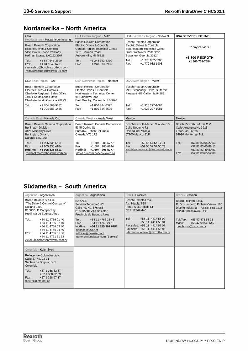
10-6 Service & Support Rexroth IndraDrive C HCS03.1
DOK-INDRV*-HCS03.1****-PR03-EN-P
Nordamerika – North AmericaUSAHeadquarters - Hauptniederlassung
Bosch Rexroth CorporationElectric Drives & Controls5150 Prairie Stone ParkwayHoffman Estates, IL 60192-3707
Tel.: +1 847 645-3600Fax: +1 847 [email protected] [email protected]
USA Central Region - Mitte
Bosch Rexroth CorporationElectric Drives & ControlsCentral Region Technical Center1701 Harmon RoadAuburn Hills, MI 48326
Tel.: +1 248 393-3330Fax: +1 248 393-2906
USA Southeast Region - Südwest
Bosch Rexroth CorporationElectric Drives & ControlsSoutheastern Technical Center3625 Swiftwater Park DriveSuwanee, Georgia 30124
Tel.: +1 770 932-3200Fax: +1 770 932-1903
USA SERVICE-HOTLINE
- 7 days x 24hrs -
+1-800-REXROTH+1 800 739-7684
USA East Region – Ost
Bosch Rexroth CorporationElectric Drives & ControlsCharlotte Regional Sales Office14001 South Lakes DriveCharlotte, North Carolina 28273
Tel.: +1 704 583-9762+1 704 583-1486
USA Northeast Region – Nordost
Bosch Rexroth CorporationElectric Drives & ControlsNortheastern Technical Center99 Rainbow RoadEast Granby, Connecticut 06026
Tel.: +1 860 844-8377Fax: +1 860 844-8595
USA West Region – West
Bosch Rexroth Corporation7901 Stoneridge Drive, Suite 220Pleasant Hill, California 94588
Tel.: +1 925 227-1084Fax: +1 925 227-1081
Canada East - Kanada Ost
Bosch Rexroth Canada CorporationBurlington Division3426 Mainway DriveBurlington, OntarioCanada L7M 1A8
Tel.: +1 905 335 5511Fax: +1 905 335 4184Hotline: +1 905 335 5511 [email protected]
Canada West - Kanada West
Bosch Rexroth Canada Corporation5345 Goring St.Burnaby, British ColumbiaCanada V7J 1R1
Tel. +1 604 205 5777Fax +1 604 205 6944Hotline: +1 604 205 5777 [email protected]
Mexico
Bosch Rexroth Mexico S.A. de C.V.Calle Neptuno 72Unidad Ind. Vallejo07700 Mexico, D.F.
Tel.: +52 55 57 54 17 11Fax: +52 55 57 54 50 [email protected]
Mexico
Bosch Rexroth S.A. de C.V.Calle Argentina No 3913Fracc. las Torres64930 Monterrey, N.L.
Tel.: +52 81 83 65 22 53+52 81 83 65 89 11+52 81 83 49 80 91
Fax: +52 81 83 65 52 80
Südamerika – South AmericaArgentina - Argentinien
Bosch Rexroth S.A.I.C."The Drive & Control Company"Rosario 2302B1606DLD CarapachayProvincia de Buenos Aires
Tel.: +54 11 4756 01 40+54 11 4756 02 40+54 11 4756 03 40+54 11 4756 04 40
Fax: +54 11 4756 01 36+54 11 4721 91 53
Argentina - Argentinien
NAKASEServicio Tecnico CNCCalle 49, No. 5764/66B1653AOX Villa BalesterProvincia de Buenos Aires
Tel.: +54 11 4768 36 43Fax: +54 11 4768 24 13Hotline: +54 11 155 307 6781 [email protected] [email protected] [email protected] (Service)
Brazil - Brasilien
Bosch Rexroth Ltda.Av. Tégula, 888Ponte Alta, Atibaia SPCEP 12942-440
Tel.: +55 11 4414 56 92+55 11 4414 56 84
Fax sales: +55 11 4414 57 07Fax serv.: +55 11 4414 56 86 [email protected]
Brazil - Brasilien
Bosch Rexroth Ltda.R. Dr.Humberto Pinheiro Vieira, 100Distrito Industrial [Caixa Postal 1273]89220-390 Joinville - SC
Tel./Fax: +55 47 473 58 33Mobil: +55 47 9974 6645 [email protected]
Columbia - Kolumbien
Reflutec de Colombia Ltda.Calle 37 No. 22-31Santafé de Bogotá, D.C.Colombia
Tel.: +57 1 368 82 67+57 1 368 02 59
Fax: +57 1 268 97 [email protected]

Rexroth IndraDrive C HCS03.1 Index 11-1
DOK-INDRV*-HCS03.1****-PR03-EN-P
11 Index
Aappropriate use 2-1
BBb contact 1-4Boring dimensions 5-4braking resistor 6-6Braking resistor
tightening torque 6-27
CCable
replace 8-3Connection
braking resistor 6-27control voltage 6-19DC bus 6-19equipment grounding conductor 6-29mains 6-21module bus 6-20motor 6-1, 6-22, 6-24shield 6-28
Connection cross section 6-21, 6-22X6 6-24
Connection cross Section 6-27Connection of the motor power cable 6-23Connection point of equipment grounding conductor 6-29
neighboring device 6-29supply unit 6-29
Control section 1-4Control voltage 6-12
data 6-12
DDesign of drive controller 1-3Device types 4-1Dimensional drawing 5-1Dimensions 5-1Disposal
packaging materials 9-1products 9-1
Documentationoverview 1-2
Drive controlleridentification 4-1replace 8-1type code 4-1
EElectrical data
control voltage 6-12power section - braking resistor 6-6power section - cooling 6-11power section - DC bus 6-2power section - DC bus power 6-3power section - insulation resistance 6-11power section - inverter 6-7power section - mains supply 6-1power section - output current profiles 6-8power section - power dissipation 6-11

11-2 Index Rexroth IndraDrive C HCS03.1
DOK-INDRV*-HCS03.1****-PR03-EN-P
Environmental protection 9-1
FFault report 8-4
GGround connection 6-28
HHolding brake 6-24
IIdentification
of the drive controller 4-1inappropriate use 2-2Installation
electrical 1-5
Jjoint bar 6-29
MMains connection
tightening torque mains connection 6-21Marking the components 4-2Maximum allowed braking current 6-25Motor
holding brake 6-24replace 8-2temperature monitoring 6-24
Motor connectiontightening torque motor connection 6-23
Motor power cable 6-23Mounting position 5-7
OOutlet temperatures 5-7
RRecycling 9-1Replace
cable 8-3drive controller 8-1motor 8-2
Ssafety instructions for electric drives and controls 3-1Scope of delivery 4-3Supply unit
connection point of equipment grounding conductor 6-29
TTechnical data 6-9Temperature monitoring 6-24Temperatures
above top of device 5-7Touch guard 7-1Type code 4-1

Rexroth IndraDrive C HCS03.1 Index 11-3
DOK-INDRV*-HCS03.1****-PR03-EN-P
Type plates 4-2Types 4-1
Uuse
appropriate 2-1inappropriate 2-2
WWeight 5-7
XX1 6-20X3 6-21X5 6-1, 6-22X6 6-24X9 6-27XS1 6-28


Bosch Rexroth AGElectric Drives and ControlsP.O. Box 13 5797803 Lohr, GermanyBgm.-Dr.-Nebel-Str. 297816 Lohr, GermanyPhone +49 (0)93 52-40-50 60Fax +49 (0)93 52-40-49 [email protected]
Printed in GermanyDOK-INDRV*-HCS03.1****-PR03-EN-PR911307049